


Jond
-
Posts
763 -
Joined
-
Last visited
Content Type
Profiles
Forums
Gallery
Events
Posts posted by Jond
-
-
Thanks Keith I really liked your use of black construction paper for the photo in your build log. It was really clear. I am making a new foresail and will focus first on clew and head attachment up grades. I shall then relash new sail to spars and reset using your diagram to the hoops.
Cheers.
Jon
-
Keith
I love the photo of the small triangular"fisherman staysail" instead of the top sail you posted. Looking at the images in your following post it is clear of what you are saying to be a challenge. It would be possible for a clewline to raise the topsail tack up above the Maine head stay, but unrealistic. I would guess it would be better with a continuous halyard (like a fisherman staysail) then drop a raise the topsail when tacking as they did a fisherman sail?
I am not saying any of this with authority. I am only an interested student. We are off to eat too much turkey today Thanksgiving.
Enjoy the season.
Cheers
Jon
- John Allen and mtaylor
-
 2
2
-
-
-
hi Keith
the blocks come for the Bluejacket company site. They are a long time modelship company here in Maine and sponsor of NRG. I use them because in the large scale and need to able to sail they work well, as I can do things like relocate back stays, and the lines run through them reasonably. Also for the use of attachment both of strop or becket they have strength.
cheers
-
Upgrade the main boom
This step is a bit complicated and I will make at least two postings. I am finding my way through fog a bi,t but that is appropriate for grand bank fishing vessels. The first post is to share the research, show some options and share the first fix I completed. I keep wondering if the information regarding BN ll is really applicable? While there in Lunenburg, the captain confirmed a few changes in rigging from the original, I pointed out to him as coast guard requirements. I believe there are a few more involved with the main boom. So, I share my thought process below with photos:
·
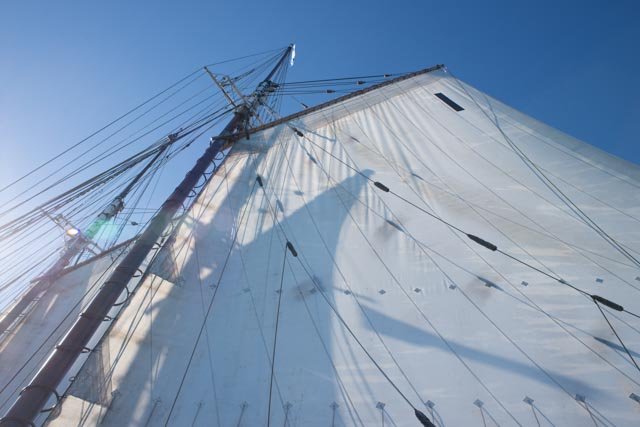 Here we look up at the main sail and see three systems of boom lifts
·
 Looking aft we see the forward lift then the midpoint lift is banded aft of the main sheet bale and the end lift is at the boom end.
·
 Looking up at the dock side we see all three boom lifts and the lazy jacks as well as the peak halyards. Lots of lines, not seen on BN photos
·
 Here is a detail of the forward lift. I beleive this is new but so far have added it to the model.
·
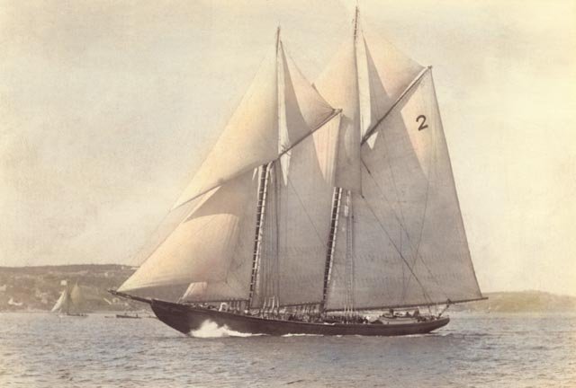 Here we see Bluenose sailing from a NS achieve file. There is a mid-point lift near the sheet bale. There is no forward lift and I don’t see the end boom lift. Most schooners had them, the captain told me the original had one. The Eisnor plans do not show any other but what is in this photo…
That raises the hard question. I am still struggling with final solution for my model but have several other items we can do.
·
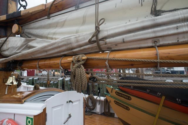 Here we see the boom tackle being made to a large wood cleat on the boom, not the jaw pin as on four masted schooners and other boats.
·
 Here we see the attachment method that makes good sense for the lazy jacks. Simply sewing will do here.
·
 Here we see a detail of the metal work for both the main sheet bale and mid boom lift. Note here the lift is clearly just aft of the sheet bale. It also highlights the choice made on BN ll to use all bright work on the blocks and blacken all the metal work.
·
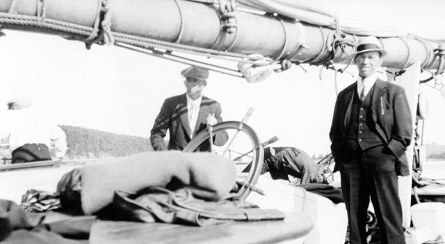 He we see a conflict. This old NS archive photo shows the two lift bales. One next to the man’s hat just has two lines going straight up like a lazy jack. The other over the skipper’s head is clearly the large midpoint lift.
·
 Here is a ns archive photo take in 1940 survey, post fishing. There is no evidence of lazy jacks and the boom lift is back just forward of the bale. Therefore, we see that this band was moved around by different skippers.
·
 This blow up of the ns archive photo just confirms the lift band was not aft of the main sheet. So like my model, the foot ropes come to the sheet bale.
My sheet bale needed to be rebuilt. It was too low and used ugly tabs for the foot ropes. I also need to use more real bolts at this scale when they are right. I found the 00-90 bolts perfect for the this.
·
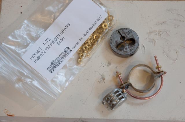 To build the bale I use 14-gauge electrical wire. It is nicely annealed and takes a 1-72 die easily
·
 Here we are in place with better connections to the foot rope. You can see I have currently placed the boom lift band forward of the main sheet. some more paint to get that galvanized look is next
·
 And here is the cable becket looped blocks taking the mid boom lift as rigged on BN ll. Sure hope I am right but now I have committed to following Jensen drawings except where I clearly know there is a change.
All for now
Cheers
jon
-
Thanks Keith
We celebrated Beaujolais nouveau last night, so I am good for another day. For me it is rebuilding main sheet bale and lazy Jack's. Here is an area where bn and bn ll don't agree. Maybe the new wine will age as I try to solve this one.
Cheers
-
Keith
I continue to be inspired by the clean and crisp imagery of your build. Now watching you go through figuring out how the rigging works I love it even more.
One of your comments was about tacking the topsail. I have read several different approaches.
- The 4 masted schooners used clew lines to gather up for top mast furling. It was thus a two step partial raising by clew line and the tack lines p&s transferred to allow tacking across the spring stays, lower gaffs and peak halyards etc.
- Bluenose has clew lines but the stories tell of a brave crew member staying aloft to pull the sail over and transfer the tack line while racing.
If the topsail is raised from the deck . Perhaps having a double tack line would be enough to pull the sail up and let it flow over. Perhaps a lighter traveler line could have been rigged to pull up the tack ( opposite action of the jib down hauls)
Anyway I love learning more about how these boats worked. And I love learning from logs like yours
Thanks for sharing
Jon
-
Fix the main boom lashing
Now that I have the main boom available for my thumbs, I needed to remove the spiral lashing. Let’s see how it went.
·
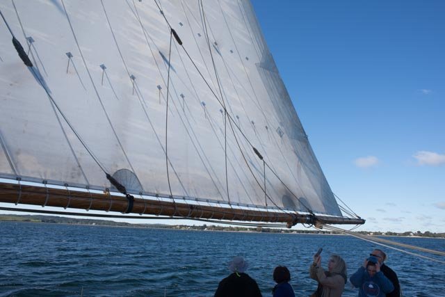
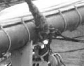
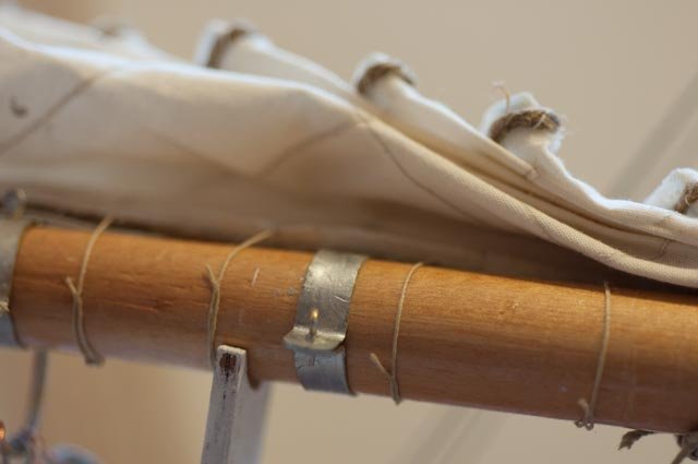
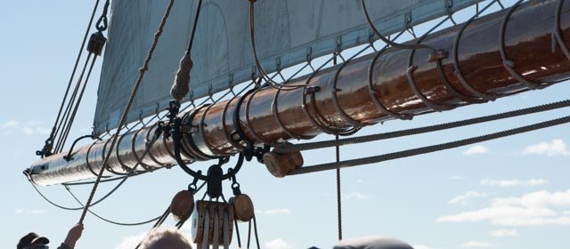 Here we see an image of Bluenose ll main boom under sail. This is the image that I am trying for. A few exceptions however, as I have figured out this rigging is not identical to the original Bluenose. The lashing looks right however, so that is step one.
·
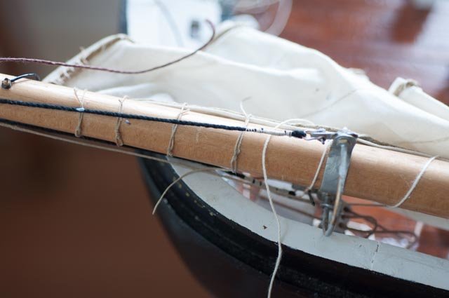
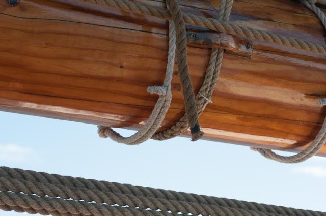 Here is a detail and it shows the lashes wrap under to a square knot and the ends then tuck through a single strand of the line on either side. You can also see the outer topping lift line passing forward to the pin on the port side jaw. Please remember this image when we move to lazy jacks.
·
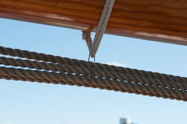 Here the boom tackle gets tied up to avoid sagging.
·
 Here you see on the model I had fixed the first lashes aft of the main sheet bale.
·
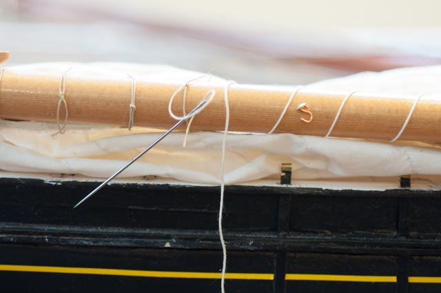 Here is the needle tucking the end through. Most lay perfectly parallel but some are stubborn. Wax helped, though I fear more fabric glue will do the trick.
·
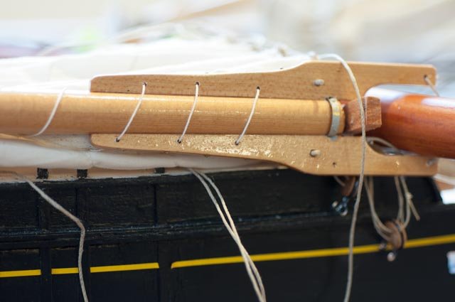 Here is a challenge. Like previous models I had staggered the jaw holes. That is wrong, and I shall plug them and align them as I go.
·
 Here we are with the lashing done and the mast re-stepped.
Oh for the breakage…..chuckle
Remember the little top mast extension.
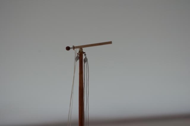 I chose not to stress either dowel or mast by using a brass pin. I used a tooth pick to pin it so that the tooth pick would be the weak link. I was right; even the weight of the light strings and the waving around was enough to break the tooth pick. So far so good. when i was moving the whole boat for cleaning up and the camera hit the for stays, this tooth pick broke again. It might be too weak a link, and I need to think about it, perhaps plastic tooth pick. For now though it's easy to fix and it causes no mast damage.[ I do not glue this connection]
cheers
jon
-
-
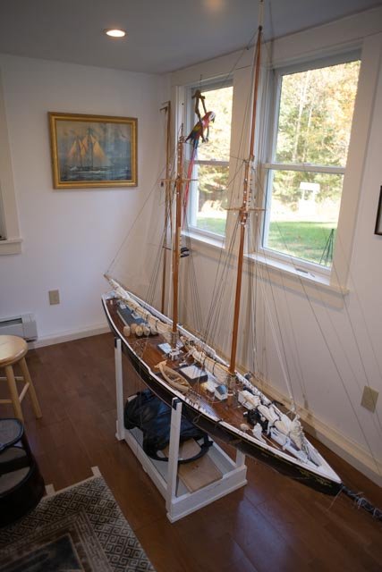
Thank you all for your concerns regarding going back together after demasting. Before I posted the demasting, I completed several upgrades on the boom , installed what I call the mast boot and put her back. It works; yes with some breakage and other issues I shall share. It definitely is not for once a week but may let me set the detailed lines and things aside and then add simple masts and sails just for sailing. More on that as I work it through. At least I can transport her to the Owls Head Museum show next march, and now have a scheme to let her sail if only once.
i chuckle to see insanity listed above as a suggestion of my mixing scale with sail. I am using a new word...analidity to describe some of my plans. But that is what this is all about. Anyway, each time I move stuff, something breaks. Today the camera tripod fell on the bow sprit and broke a clip holding stays. Fortunately the 'sailable' bottle style turnbuckles are strong and the replacement was a simple brass founding.
anyway I am struggling on a few things today [ remaking the main sheet bands to be correct] and hope to update in a day or so. I plan to remove the foremast next week.
cheers
jond
-
Take out masts
I had an epiphany. If I improve the bolts on the chain plates and critical shackles, I could remove:
· 20 bolts on shrouds
· Three turn buckles on stays
· Three sheets [ add bolts in shackles]
· Cross stays above [ add bolts in shackles]
· Jumbo boom gooseneck figure it out add bolt
· Back stays two lines and deck blocks for each mast
· Halyards, whips, boom lifts etc . say 20 lines now 30 lines later
In maybe an hour or so I could remove the masts. I am not sure where this is going, but just to make some improvements on my current lists I need to get the masts out, so let’s try it.
this could have been a big oops let's see how it went.
 I ordered more small bolts. i chose the 0-80 as they are a little more robust and if they are going to come out and go back that is important. I had snipped them to length. That crossed up the threads to help keep the nut in place, but that prohibits re-threading. In this photo you see I am trying new bolts at the right length. First on the left shroud is a new 1/4 in bolt...too short. The right shroud has a 3/8 bolt...too long Oh well I should have known no standard sizes would work here. Now i have two more bags of mini bolts.
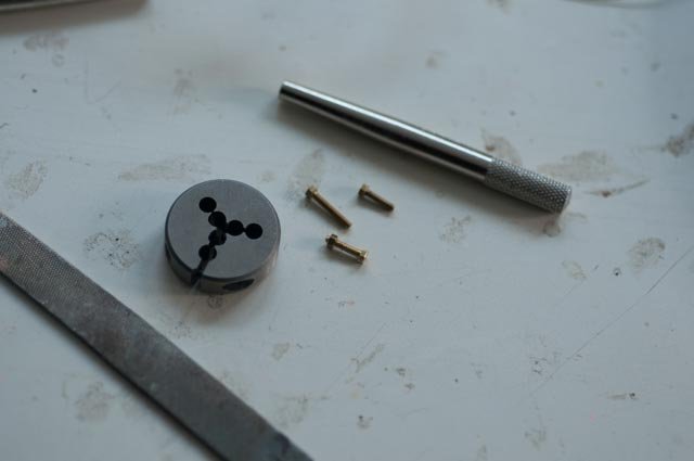 Here I have filed and chased the threads with a die so the right length bolt is ready to go
 Here i demonstrate the use of two mini bolt sockets that make this a reasonable option, especially if this is to be done and redone. You can see the black paint falls away from the brass, but that's no big deal as I am constantly going to be touching up if i choose to move this thing.
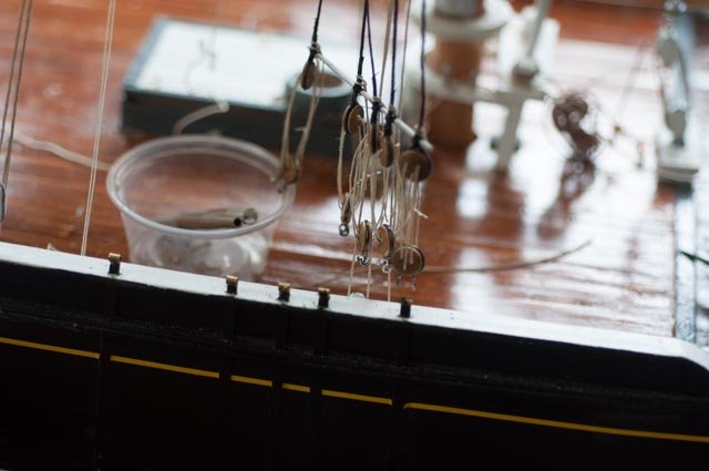 here the first set is off and bolts saved in the plastic cup. yippee! I normally end up on the floor looking for that errant nut.
 Here I have untied and grabbed all the lines tight to the mast. simple masking tape to hold things from getting too messy.
 Now lets start working on upgrading those sheet blocks to see where a simple nut and bolt is all that is needed to disconnect. this is 0-90 bolt.
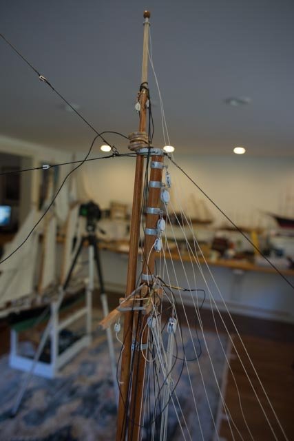
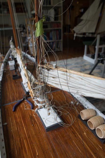 Here is better view to the spaghetti taped to the mast. wish me luck on this one please.
 Now for all those cross braces. i like the idea of upgrading these shackles and ties through the bales to 0-90 bolts and nuts. I continue to use copper instead of brass for the bales because as here , I effectively chase threads into the copper as I install the bolt the first time. I suppose i could tab a bent loop if it were brass, but I find it too difficult to bend the brass as it is not fully annealed. Since I am painting it I currently stay with the copper.
 Well here we are finally ready.....Shall we lift the mast????
 It came out...we'll discuss what happened when it's time to restep. not too serious, and if we made it, we should be able to fix it right??
cheers
Jon
-
-
Keith
Thank you for you encouraging words. It is your build that fills us all with awe. I have been inspired again thanks to you to try to use soldering and my late brothers Sherline to actually make a fitting. I need to have more bolted shackles connecting things as I am going to figure out how to remove and reset my masts for transportation. The copper wire bending only goes so far. I also note your use of brass wire for hooks. I struggle bending the brass but it would be stronger.
Cheers
Jon
-
Patrick you are too kind as usual. when I look at your interiors on you pages I am stunned at the patience and steady hand you have. an that is real detail.
as to 1:24 scale detail, I am in the awe stage... possibly also known as the upper part of the Rabbit hole i have entered. Like do I need to redo the parrel through the front of the boom Jaw?
anyway thanks for following
jon
-
Derek. many times I cheat when bending planks with little to hold them.
- I soak the plank in ammonia water for a while ...not too long say an hour...then put a few in place with clips [ much less stress] and let them dry. they don't have to be perfectly fit as you are trying to get most of the bend into it. I come back the next day when they are dry and they glue up with much less fuss.
- I also bought long pins with little plastic ball tops at Joann's. I drill down through a part [ it could be rail I am bending or post and on occurrence a temporary laminated plank that gets removed afterward] then temporarily pin it in place. If it's stubborn, I CA the pin too.....then if too hard to remove pin, I cut it off and leave it in. I used this to build most of my waste planks, monkey rails etc. I know my model size is bigger and if i sail her strength is more important so some of my pins stay in for that purpose..... but it worked
what your doing looks great....good luck getting through this step. I believe it is one of the tougher stages of this build and yes that often means twice. It sure did for me. I am redoing many things as i learn.
cheers
jon
-
Add back stays to rerun halyards on the main mast:
I mentioned in an earlier post that I found in Lunenburg that most lines are a rich tan colored hemp traditional style. To replicate that I went to the Montreal hobby store and got several sizes of their tan lines. Rigging lines on board adds a challenge for making splices.
·
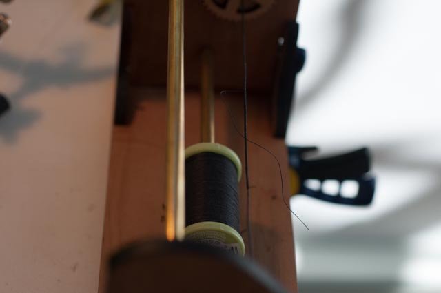
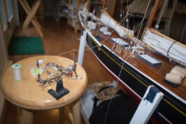 Here again I have set the spare hands on a stool and after running lines feed them out to allow splicing. I then pull them back through and make them off.
·
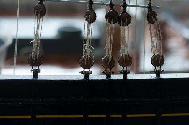
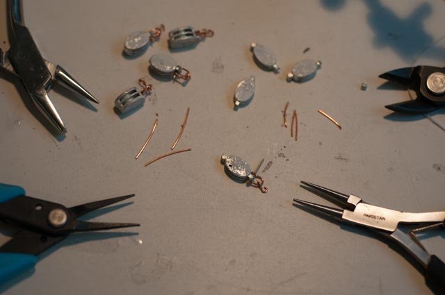 Here in order to make up blocks for the back stays I am adding both shackles and hooks to the Bluejacket blocks. I then paint the blocks white and the copper silver for the galvanized. There is some confusion in photos because the Bluenose ll chose for natural color on all blocks and black paint on all of the metal work. I have decided to take the forged rods on mast bales and the like and repaint them black but am keeping galvanized look for the fittings and bands as the lower deck photos hint that to be correct. This is a choice as there are not enough old photos especially with the rigging to clarify this point.
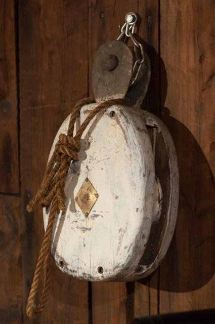 Here for the record is a block from Bluenose peak halyards. It shows the white paint and light remaining galvanized roller bracket on top. The block would be upside down as the roller rode on the "wire bridles" as named by Jensen" lines spliced to the gaff.
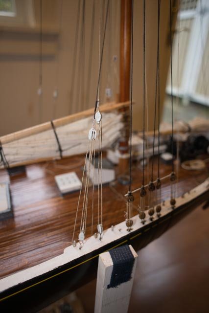
·
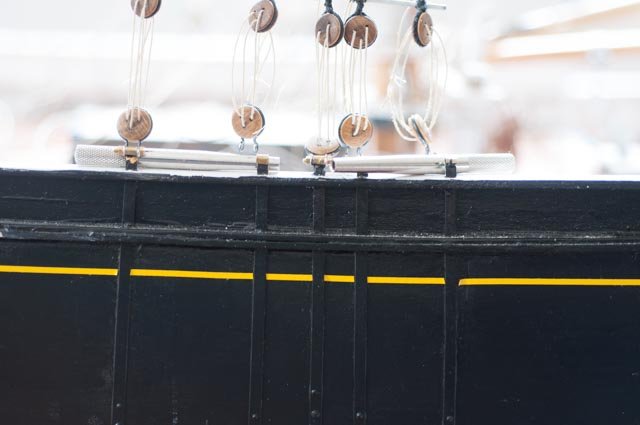
Here we see on the rail the throat halyard whip and the back stay. I chose for now to have one back stay here and the port side in the aft position. That is important, so the lines are the right length. With the throat whip to starboard, the throat main halyard drops to a block on the deck on the port side.
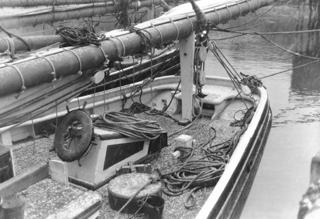
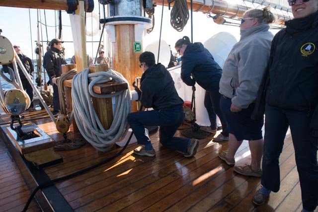 Here you can see the crew feeding the main throat halyard for the final step of raising the sail. The Black braided halyard went through the large deck block and ran forward to the winch [ capstan] port side. The peak Halyard ran forward similarly on the starboard side and you can see it on the deck past the mast. The gal standing at the right of vertical halyard has 'dogged' off the halyard with the lanyard. the hitches are just below her hands. The Lad is taking the halyard off the winch and making it fast to the forward pin. They then coil the halyard that had reached the forward capstan on the deck next to the mast while sailing. The white braided fore sheet on the port bitt. These deck blocks do not typically show on model plans. They are also used to raise the top mast. The fore mast is a little different and I will share that next time.
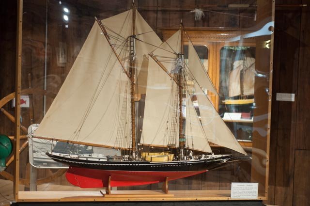
I thought it to be reasonable to share a photo of the main competitor to the Bluenose in the 1933 and 1938 races, the Gertrude Thebaud…..Gerty, as she is displayed in Lunenburg. She has been moved and now lives close to the trophies honoring the races. Many details are similar, though she was smaller. It is a great model to study.
cheers
jon
-
-
This posting is to record two more items on the list of corrections involving spars
Jaws and parrels
·
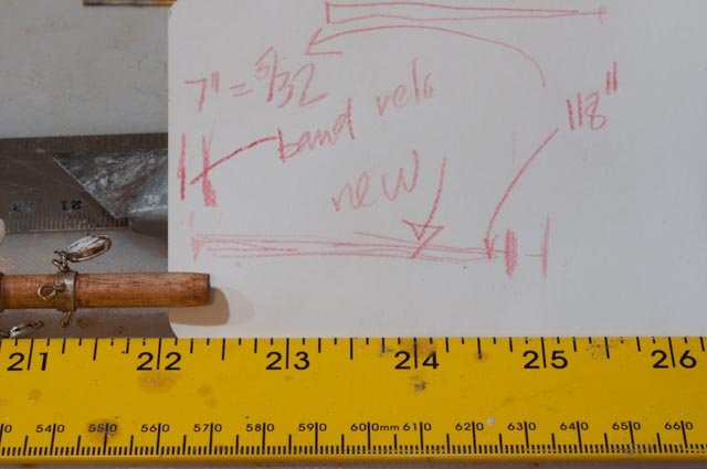
 Here one sees the correct dimensioning and counting.
·
 The model plans had very long jaws.
·
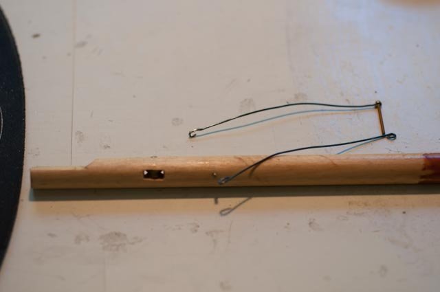
 Here you see the extension forward of the mast. The Jensen plan gave much tighter dimensions and the pencil mark is right.
·
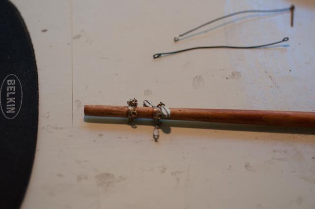
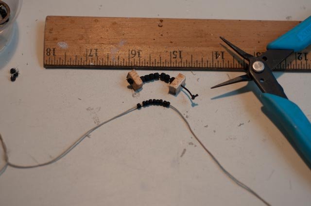 Here you see the large beads I used for 7 balls on the parrel. The size and number for the main was smaller and 9 each.
·
 Here is a the main fixed
·
Mid main boom topping lift.
This goes lift up slightly forward of the main sheet band. Model drawings did not agree, some show common with the main sheet band.
·
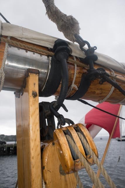
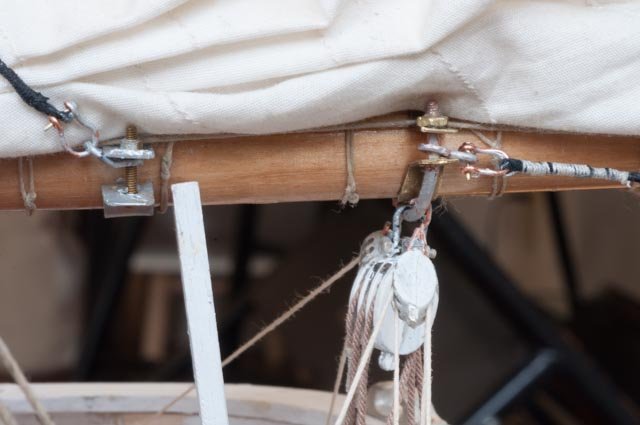
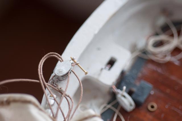
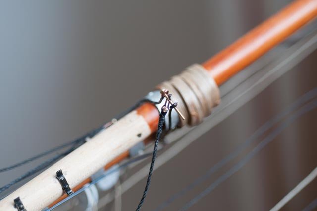
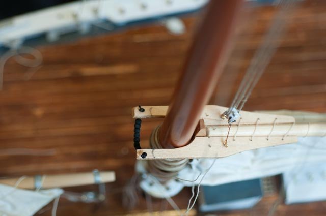
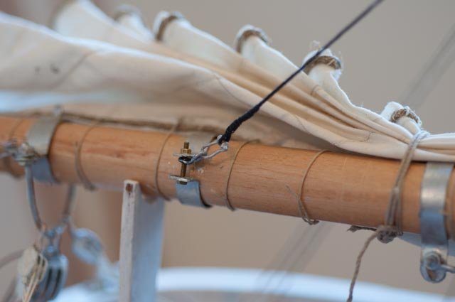
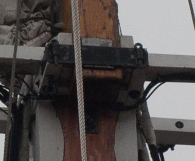
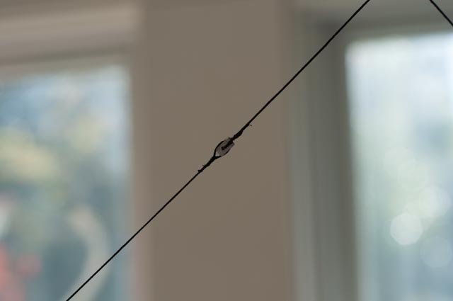
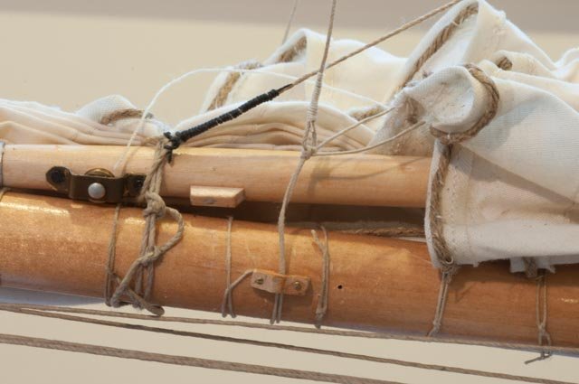
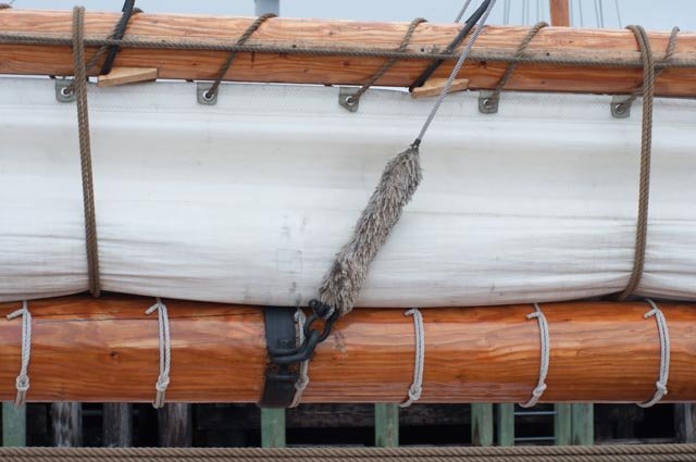 Here we see the proper fitting for the mid topping lift on the main Boom. Note the two horizontal tabs and vertical bolt leaving a gap of about 3-4 inches. There is a bent figure eight ring angling upward to carry the spliced cable boom lift around this bolt. Behind the bolt the outer topping lift lead is fed on its way forward to a pin on the jaws.[ port side ]
·
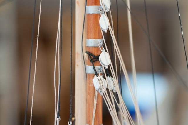
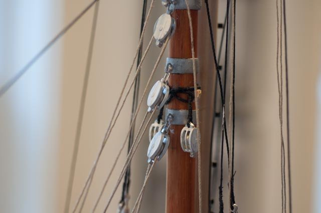
See on this photo there are two becket cables wrapping the mast above the second band. Two small ears support the dead load before tensioning the lines.
· Here we see the ring on the model based on not having enough
 information. I had two rings to pick up the lift. There is also confusion on the model drawings that the Jensen drawings correct as to where these lines go.
·
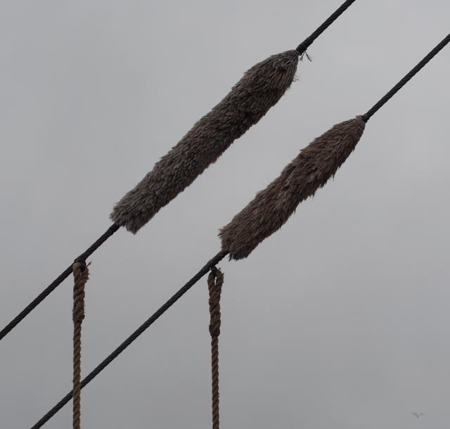
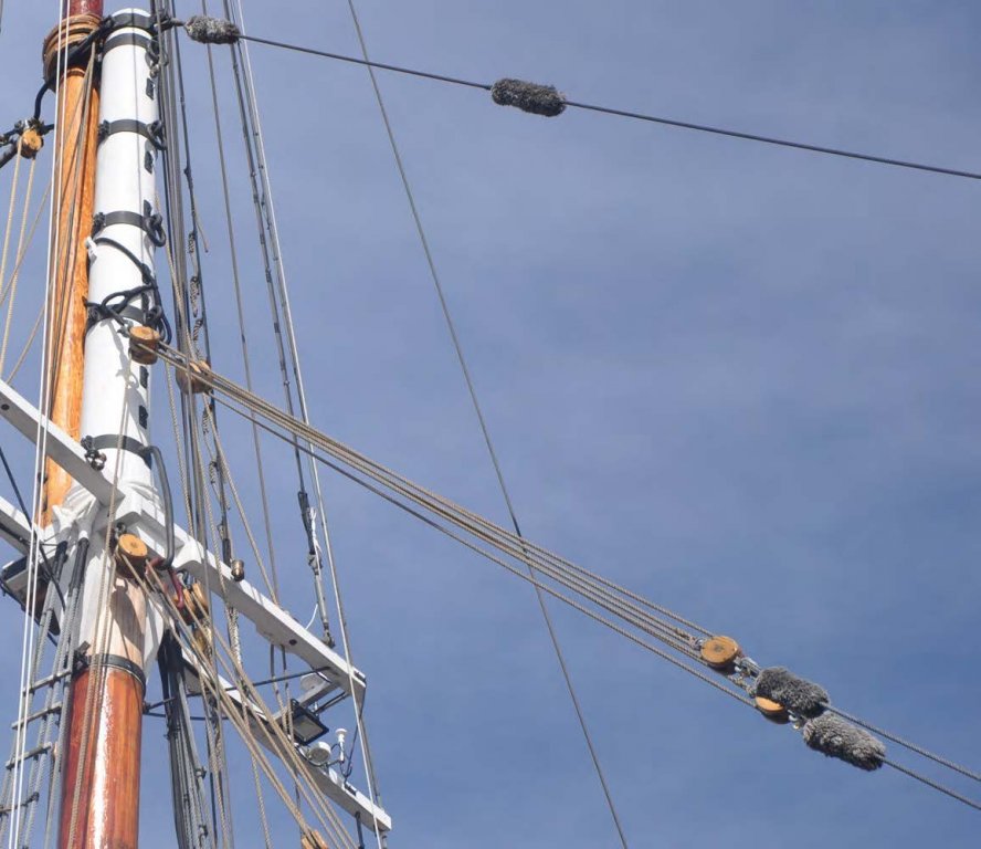
 Here we see the corrected band with figure eight bent ring, shackle and spliced steel cable. Now I need to figure out the baggywrinkles. They are about 1-1/2 inches long and roughly a ¼ in diameter.
·
 Here we see the just installed top blocks on beckets. The paint on the blocks is being touched up before I run the lines.
onward we march
cheers
jon
-
-
Thanks for these last black smith lessons. The way you support pieces as they are set for braising makes good sense. It inspired me to try harder.
Thanks
Jon
- mtaylor and Mark Pearse
-
2
-
I find working in this scale wonderful as it allows learning so much more about the boat. Reading you blog is also such a joy as your knowledge and skills are so far above me. This inspiration Al...and then the photos...thanks
- aviaamator and mtaylor
-
2
-
It has been a few weeks and I have used the old trial and error method more than once. I also went to Arizona and road on a mule along the south rim of Grand Canyon. please believe me; that was not my idea. It was pay back for her going with me to Lunenburg.
Today I want to record the several items entailed in my effort to bring the masts up to snuff regarding the need to be close to true detailing at this large scale. This post affects the top masts. First lets look at Bluenose ll and refer to the newly aquired Jensen plans
·
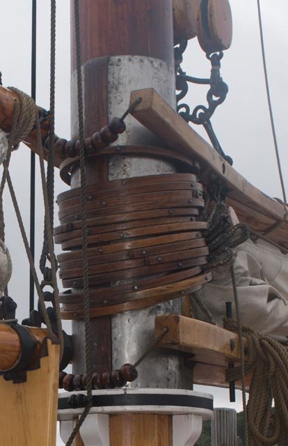
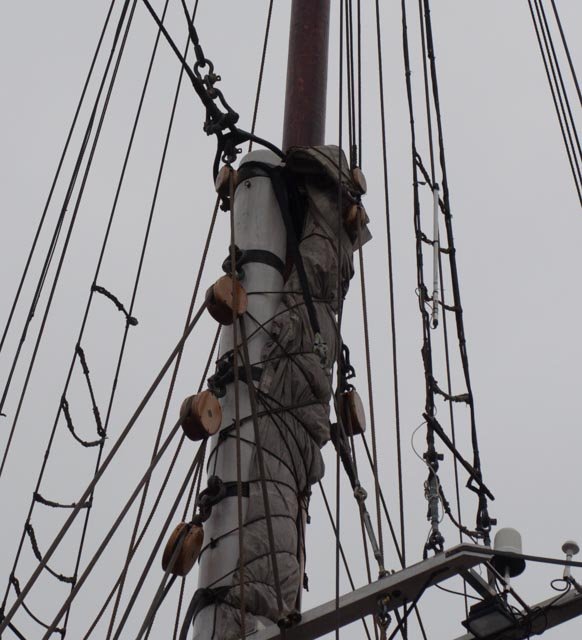
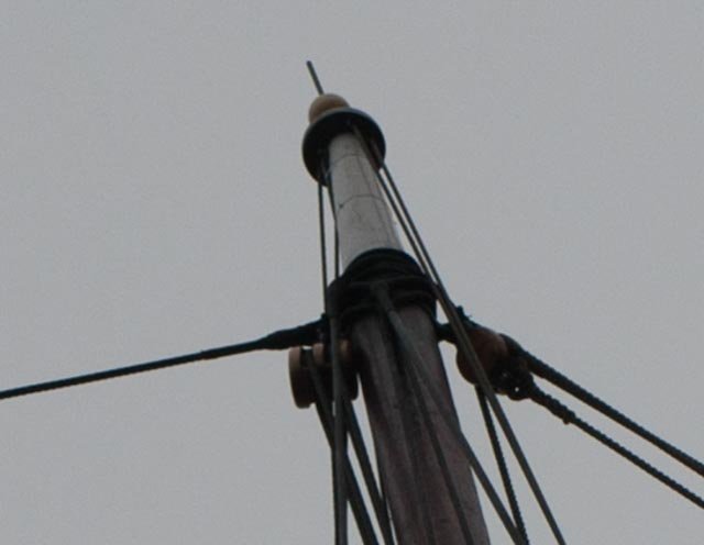
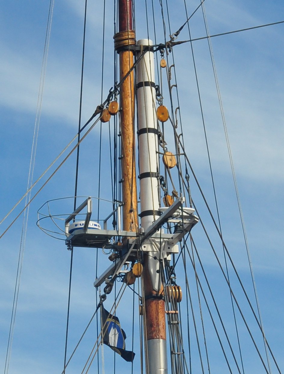
 Here is a cropped photo taken in 2014 of the fore top mast from the port side. The black clips forward of the top mast for furling the topsail are clearly shown here and on the Jensen drawings. The drawings show seven, but the photo shows six. One can also see the black rod that grabs a through bolt carrying the top mast load up to the mast cap. On my model I had attached that rod to the second to top band as had others in the Lunenburg models I saw while there in 2014. A very small detail I learned while talking to the Bluenose ll captain the night we arrived. The small blackened hole at the bottom of the top mast, just below the bolted rod is the Canadian style fid. It is a drilled hole slightly chamfered and blackened with a hot iron so the boom hoisting line will run through. The American schooners inserted a sheave at this point to facilitate raising the top mast. A becket cable [ double ended spliced cable] with two blocks are draped over the mast cap to carry that line when the masts are set or lowered.
·
 Here is the same top mast in 2017 from starboard side with the top sail furled. The furling favors the starboard side. There is also more clarity in this shot of the iron work holding the jumper stay and main topmast stay to the mast cap assembly. also note the rings holding hooks on the large peak halyard blocks.
·
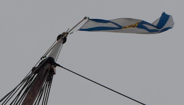 Here we see a cropped photo of the main top mast. There is a significant shoulder in the mast. Here they painted the top section white and the top ball gold. Looking at the Jensen plans I learned the disk at the top of this section holds port and starboard sheaves for flags. The flag is on its own spar and run up to the disk.
·
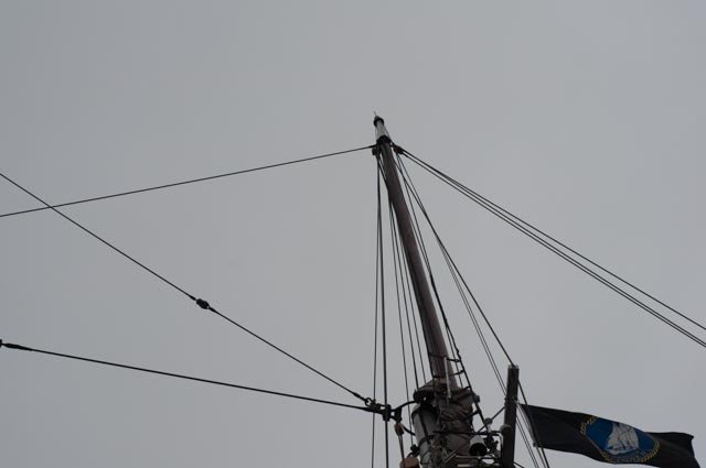
 Here we see the fore top mast. A similar detail with a 5-foot extension above the shoulder. On both masts, all for the stays and shrouds are spiced loops draped on the shoulder.
·
 Here we find the jumper and top mast stays are each made of two pieces joined at a fixed block. I did not get an explanation why as they are made up as the mast is raised. The main fore stay by example is made fast before the top mast reaches its peak position.
·
 Here we find a cropped detail of the gate holding the top mast in place. The whole thing is very tight, and I need some work if I want the top mast to come out for travel.
Now let’s look at the model and see what I had and the fixes
·
 Here is the fore top mast. Based on the modeling plans small iron bands and many eyes are placed at the top to carry stays and shrouds, halyards, clewlines flags etc. oops
·
 Here is the main top mast note the lack of significant shoulder needed for looped shrouds
·
 For the first fix, before removing things as I was still dithering on how much to undo, I made up the three small cable connector blocks.
·
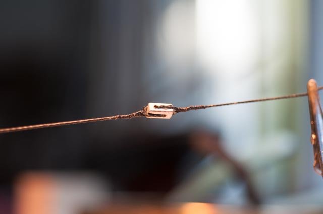 Here the first one is connected at the desk top
·
 Here is the first one in place
·
 Here all three are done and in place……oops too early as I finally decided to do much more.
·
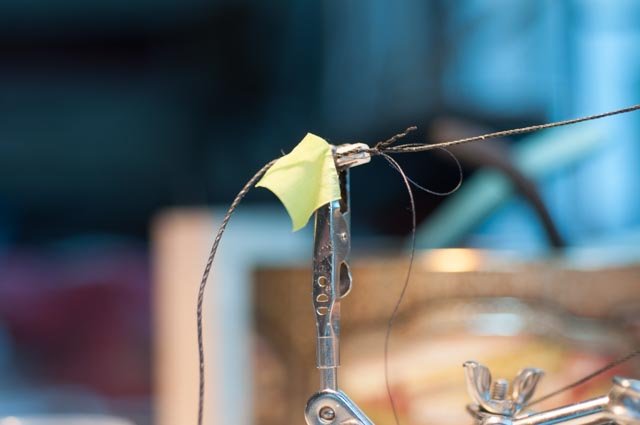
 As part of this process I got out the serving machine and started finally to us it. I seized about three inches of each top mast pair of shrouds and then made the loop and over wrapped to make the slice. It’s a good detail, but I do not think very visible at the top of the redone masts. It was however fun to learn to do. The first ones are sort of OK like everything else it takes time to get them good. I also just read an article suggesting using varnish instead of fabric glue. I want to try that
Now the top masts. They needed to be rebuilt. The Jensen drawings gave me much more detail. And I needed to remove damage from have installed sheaves.
·
 Here you see the bottom of the main top mast. The sheave is there and the rods that held to the band on the main mast.
·
 Here is the top with all those blocks. Note there is no real shoulder and reduced top section nor a disc below the ball.
·
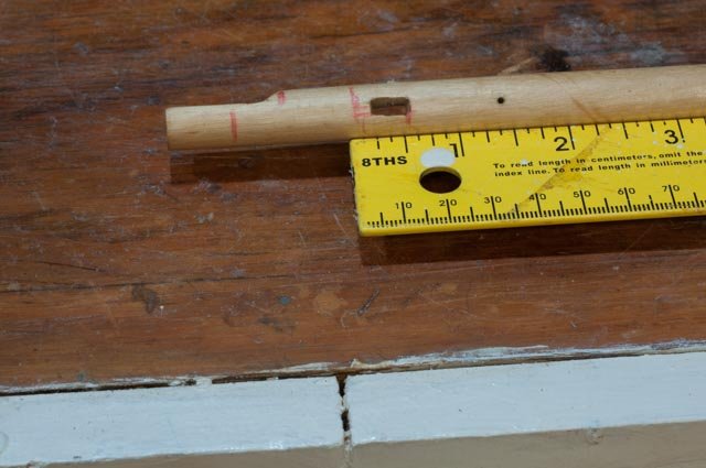
 Here I did a measurement and decided that the top 5-foot section could best be attached. It is to be a pinned dowel. That better reflects the shoulder that was not evident in my current mast.
·
 This decision allowed me to cut off the offending bottom
·
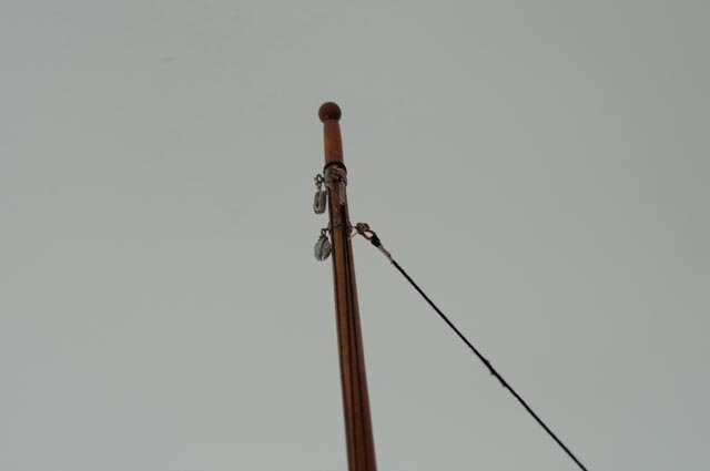
 This is the new shaped top section of the mast. The Bluenose ll is painted white. I will not paint it but leave is natural like the bottom of the main mast that is visible in the old photos
This is the point of decision. I have been convinced for some time that if I could make the top masts removable I could figure out how to transport the 4-foot-high model. Perhaps even display the main top mast being erected.
·
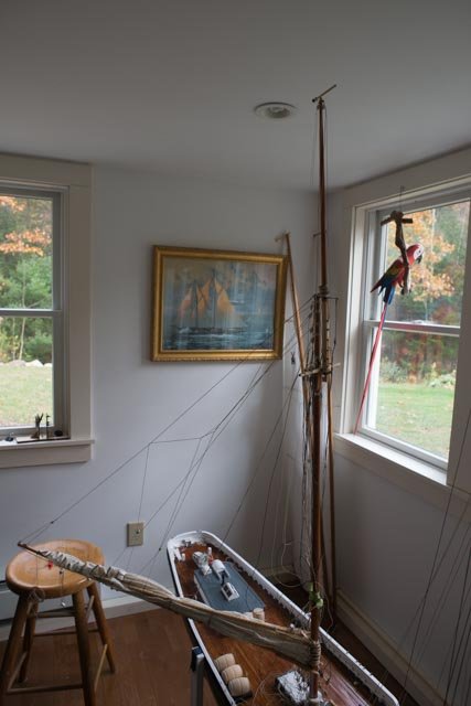
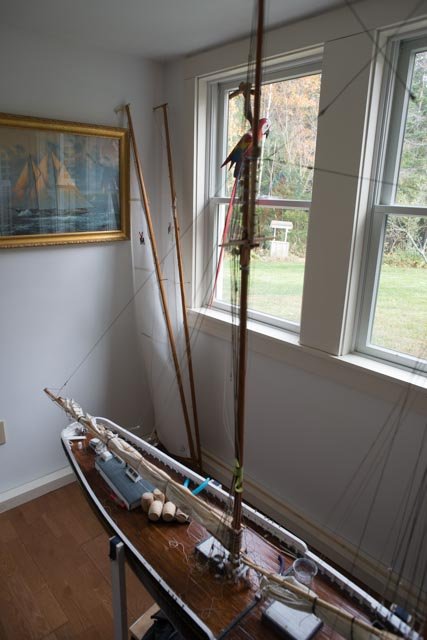
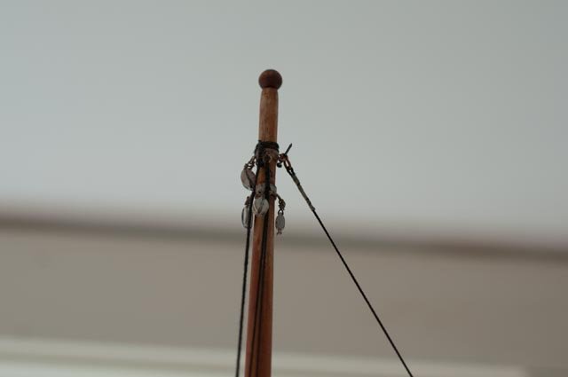
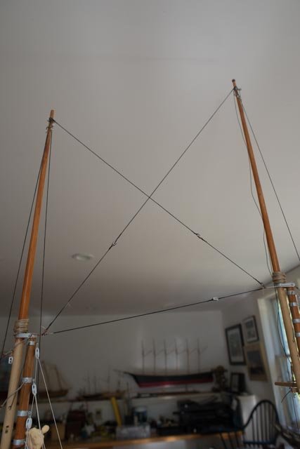
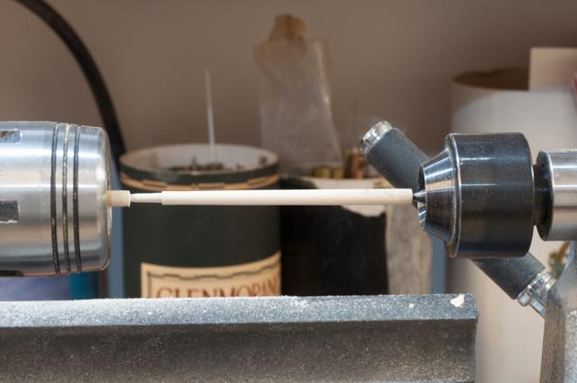
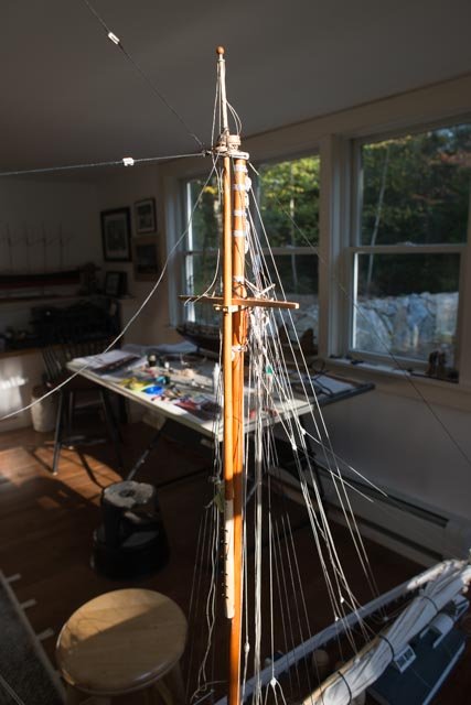
 So here is the possible set up with the main top mast being lifted.
·
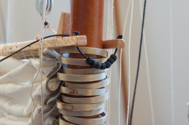
 Here is closer shot where the shoulder is holding the new shrouds in place. There are still two blocks, forward for the fisherman staysail and aft for the top sail. The topsail clewline block is sewn onto the sail, and the two flag lines use the sheave in the disk. The disk is a copper washer with holes drilled. I have yet decided but as of now no gold paint is going on the ball.
·
 This is the same picture just in the early morning with the bright Maine sunlight pouring into the shop. The Jensen plans show the furling clips on both masts. I have a 2014 photo where they were not on the BN ll main mast. With the topsail furled in 2017 I can’t tell. I decided to keep them based on the redrawn plans
All for now
cheers
jon
- Chasseur, michael mott, archjofo and 3 others
-
6
-
Brian
Bluenose ll was built using the same lines and design of Bluenose l. Going to their site you can find many images that will help. Once you get to the deck lot's of images help.
Cheers
Jon
- cog, Don Quixote and Nirvana
-
3

Bluenose by Jond - 1:24 scale - RADIO - Racing Schooner
in - Build logs for subjects built 1901 - Present Day
Posted
Second part of main boom upgrades
In this post, I need to record what I decided to do with the lazy jacks to get a view that replicates the 1940 ish boat photos, but also listens to the folks that tell me the Jensen drawings were accurate except for coast guard enhancements. I believe that there were no lazy jacks in the early races other than a single line that is seen in some of the distant photos. Regardless, I may have gone too far so I have installed the mid point system as it shows on jensen drawings. I have chosen for the moment not to add the inner most lazy jacks but did install the inner boom lift.
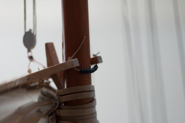
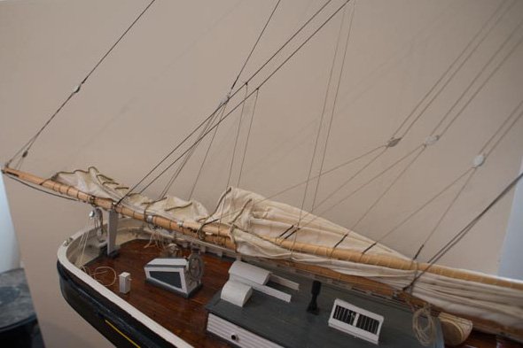
· Here we have a view of the new lazy jacks and lifts. There are two lines [ lazy jacks] falling to the boom from the mid boom lift. You can see the port side back stay made to the aft position beyond, and the end boom lift line twisted in this photo. I need to figure out how to keep lines from twisting.
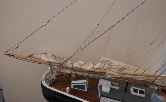
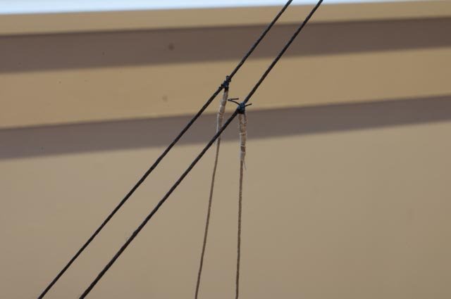
· In this view the forward lift is clearer. Also you can see an issue for a future fix,the peak halyard bridles are made of rope[ they are tan with black seizing]. I made this in error based on my looking at the old photos months ago. After seeing the real thing I looked again at the old photos and yes, they are clearly cable. This is now a punch list and some how I need to come back on these.
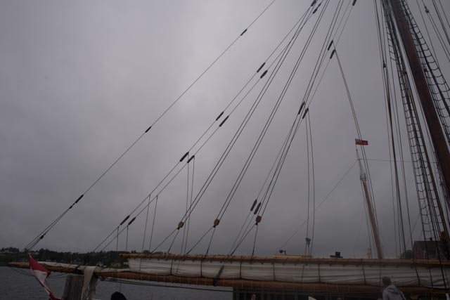
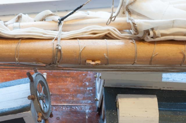
·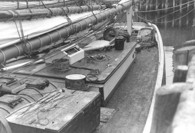 This NS archive photo gives the simple look I need to get. There is center band over the deck house that looks like it is in the same location the forward lift. I chose this to justify installing the forward lift to the blocks under the cross trees.
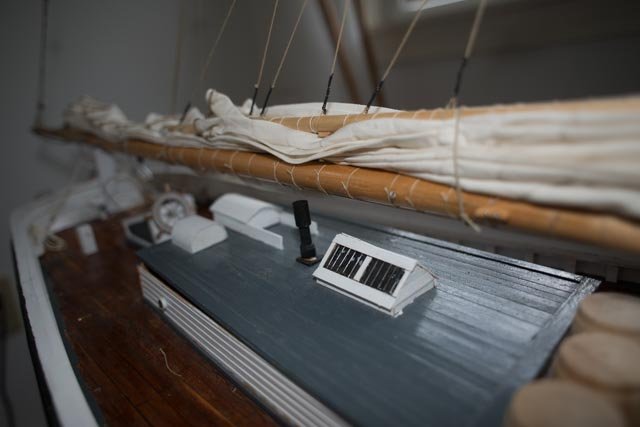
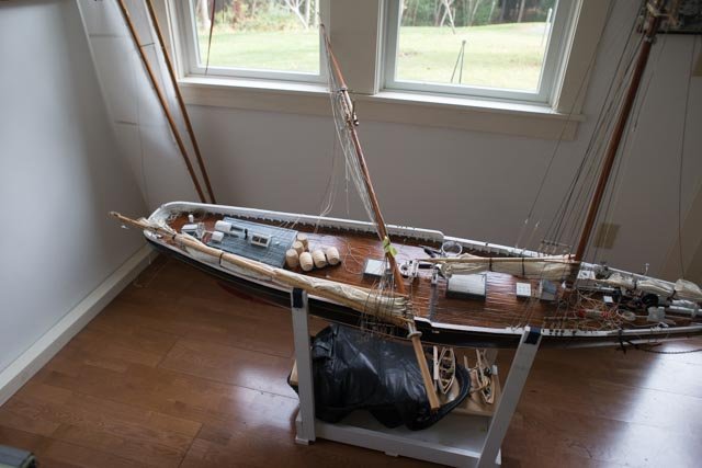
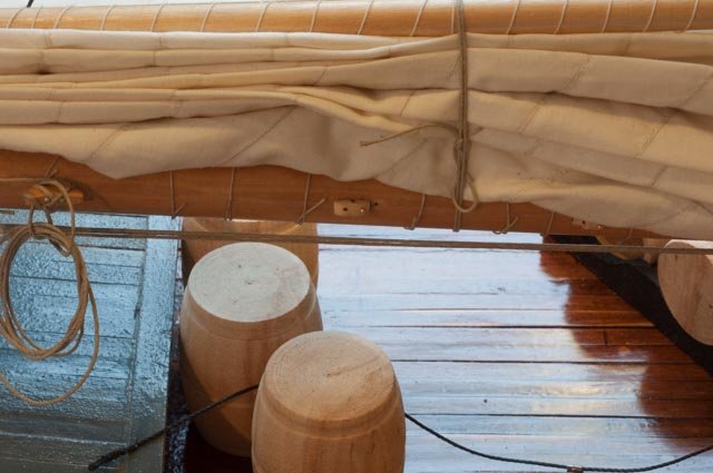
·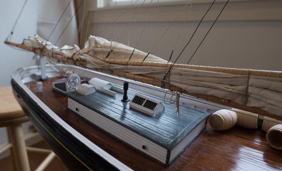 This image is just to show where we are at this point as I move on. The lashing of the furled is also in the tan hemp colored material. The bait barrels need to come soon and yes the shall.
Lazy jack details.
· Here we see my first attempt, before going to Lunenburg of the wood fairleads. Reject..
·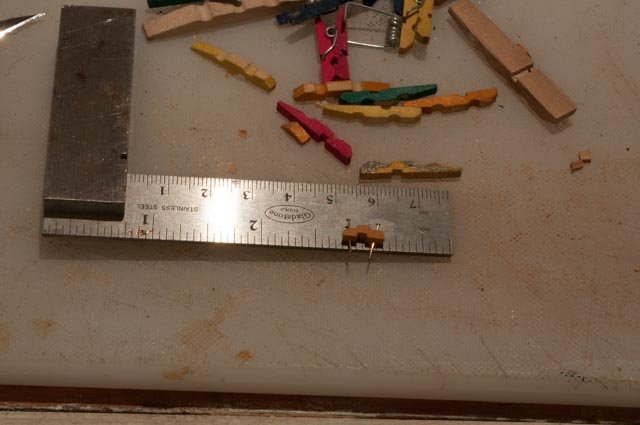 I looked around the shop for inspiration and found mini clothes pins. Some were broken so available. I cut them down and presto…not perfect at all but much better. I believe from reading more advanced builder's logs that if I had some pear or other good wood, I could file/ carve them down more and they would be even better. I am definitely not there yet.
· Here we see the fairlead in place and the two eye spliced lines ready to be lashed through the fairleads
· Now to install: the real ones are wire wrapped to hold the line eye splices to the cable boom lifts. So I sewed and tied hitches trying to respect the method.
· Below the larger line is eye splices at the bottom about the height of the gaff, then a double smaller line is run through the fairleads under the boom and tied off. This hitching is the adjustment.
Ok I am onward to the foremast
Cheers
jon