


Jond
-
Posts
820 -
Joined
-
Last visited
Content Type
Profiles
Forums
Gallery
Events
Posts posted by Jond
-
-
I remain awed with some of the beautiful planking I find. I love you lessons on using more heat too.
Congrats she looks great. Be sure if you use Wes system to opt for the clear hardener. My can says 207 for natural wood. I have not been using it where I use filler and plan to paint.
Cheers
-
Pete
When I was a kid I sailed in Buzzard's Bay, Ma. Herreshoff 12.5 's were there along with 14's, 15's and many others. I always thought that the 12.5 was the boat for me whenever I retired here in Maine. . Now that I am here and had experience in the harbor however, the 21 feet of the BHOD is a really nice add to the 16 foot 12.5. We point higher and are also faster. We were designed to race. We have a few Herreshoffs in the harbor and they remain gorgeous. The newest are the reissued Pisces 21 built up north in Brooklin maine. They are incredible and I recommend you check them out. We have two in the harbor and they beat everyone.
cheers
-
mark
thanks for the comment. I knew I read somewhere on one of these strings that preheating brass can make it easier to use. I need to get more brass stock to replace the damaged ones I started and then I will try the annealing approach to 1/16 brass rod before attempting to make it a rivet. I will eventually need the same thing as I attach the lead half bulbs to the sailing keel
cheers
-
-
Yesterday was eventful. Our new England Patriots got beat and now we have two months before baseball. The Boston Bruins hockey team is very up and down, so thankfully there is model boating. This post is a little catch up on completing the fittings...sort of anyway....
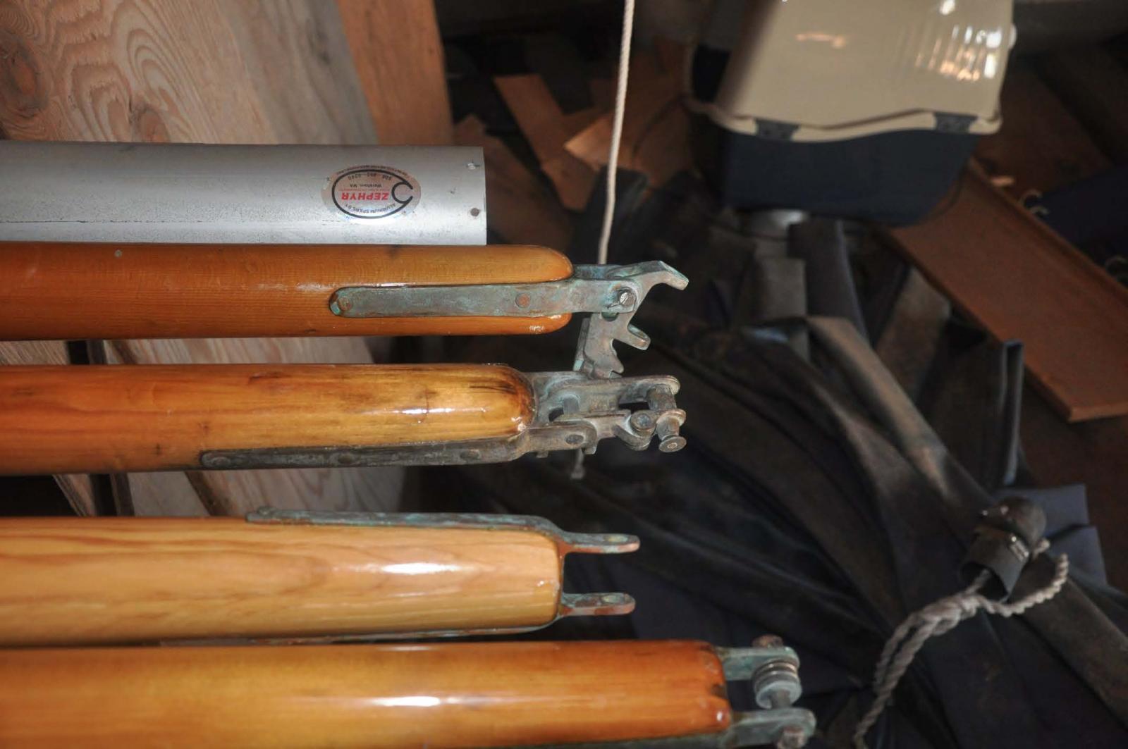
Here is the Jumper strut [ upper] on a new mast in Davids storage barn.
-
 The photo of my old mast did not come out clear. It would show a similar design, but it is all bronze. The old drawing said the struts were oak and my real boat has old oak. That grain is not good at this scale and I preferred to the look of the spruce.....so
-
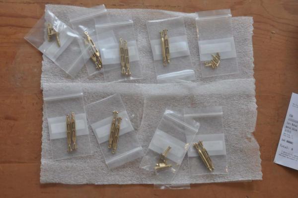
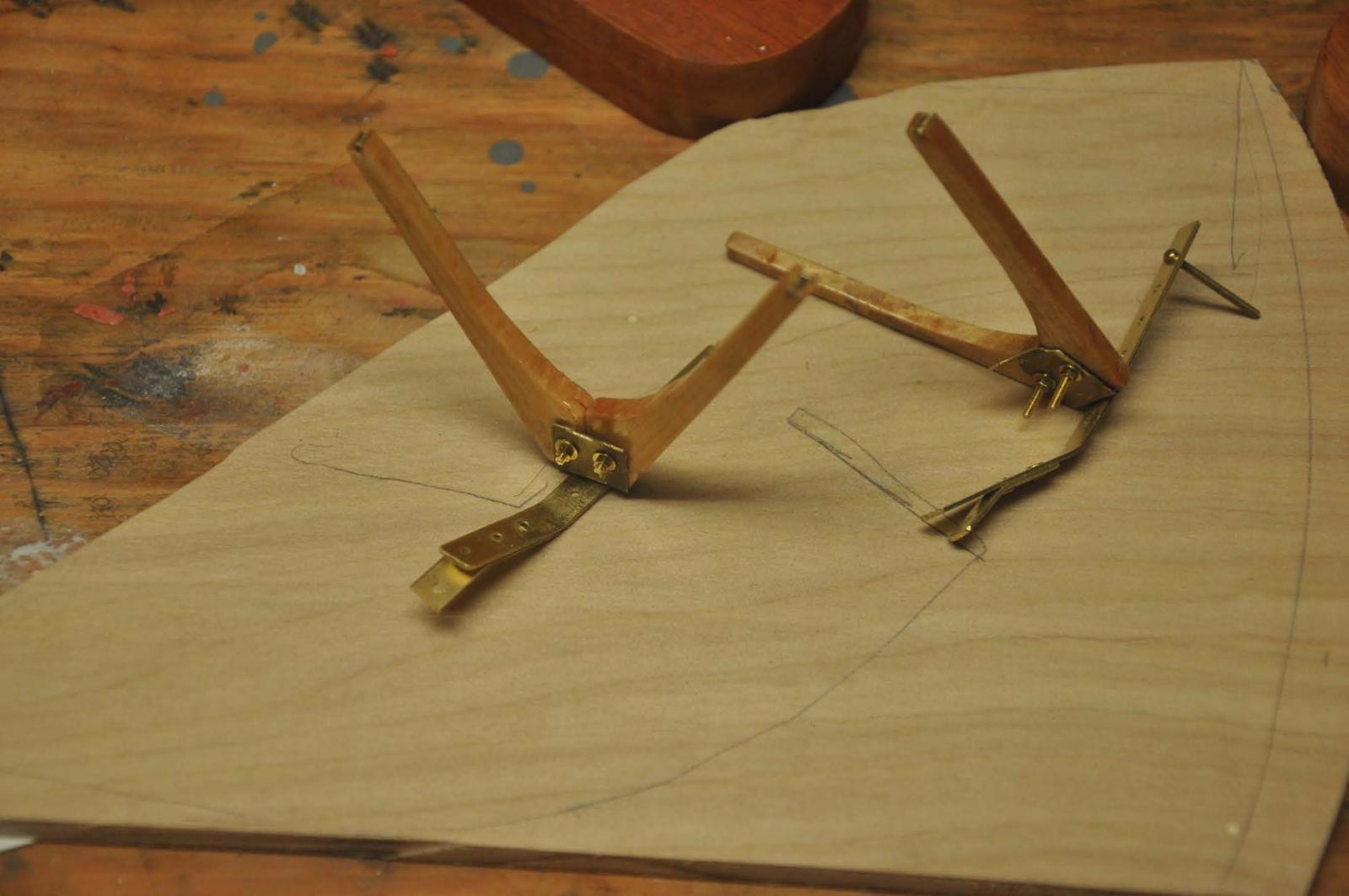
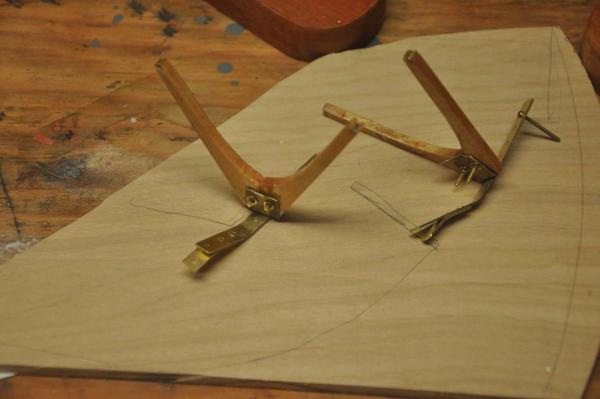 Here are my made up struts for both boats. I used sitka spruce and brass. I used the cut off form the mast and it was the perfect size.
-
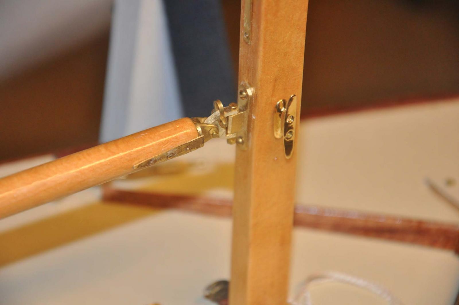
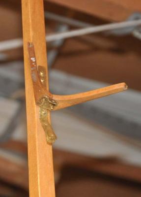 Here the jumper strut is mounted to the mast. I bought a bunch of 00 wood screws and the 1/4" were perfect. On the side tangs where there is a pair of shroud connections we have a through bolt, and I used the brass 00 cap screw only because my hex head bolts were too short. I actually used a 1/16" brass rivet to hold the 1/64" brass clip to the brass strap. I wonder if it will last??? the rivet was so short there is very little metal engaged.
to complete the mast here is the new spreader that I am making for the real Bittersweet. It is sitka spruce. Thsi is not part of the 1938 design but was added in the 1970"s I believe.
-
 I am struggling getting 1/16" brass rods to cooperate and act like a rivet because of the light gauge of the strap. I can not hammer very hard. I tried copper 14 gauge electrical wire but it was not soft enough either. we'll get there. I may have to preheat the rods before inserting them.
-
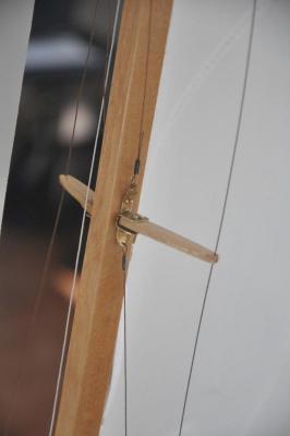 here is the new lower assembly complete and mounted on the mast. This again has a weak connection of the clip. I used copper wire staple glued into the mast because this clip is 1/32" and too thick to try a rivet. we'll see what a breeze does to it.
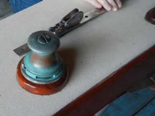
I started the tillers. They are very simple and slightly curved and tapered. There is a simple brass connection to the stuffing box to be made....
-
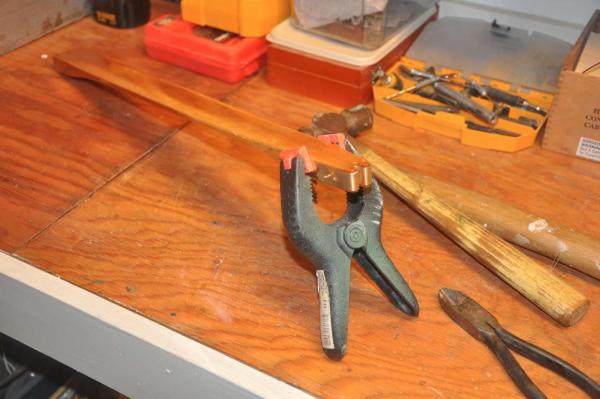
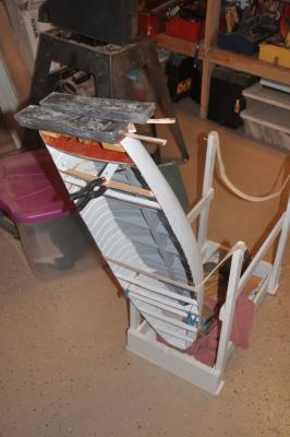
 I, like may others, bought this plank bender from a great vendor. I find it difficult to use for that purpose and it sat on the shelf for years. Here it is the perfect tool to make two tillers bend the same.
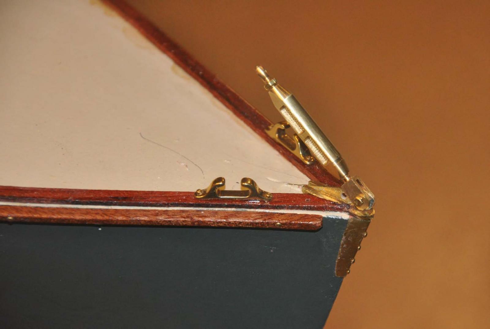
To complete the deck...again sort of...here is the addition of the mahogany bow strips and completion of the stem cap
-
 I added a second layer of brass to bring up the fitting to the mahogany. after adding the turnbuckle and the chocks I think is works. just not elegant.
So here is progress update for last week.
-
 One can see our last tasks before leaving the boat shop for the sail loft will be to install the teak sole. i have decided not to use the recommended African substitute.
cheers
- G.L., michael mott, pete48 and 3 others
-
 6
6
-
-
-
-
Here is an update with more fittings and progress. I will try to consistently show the real boat fitting and then my attempt to replicate it. so here we go...this is a real learning experience for me
gooseneck:
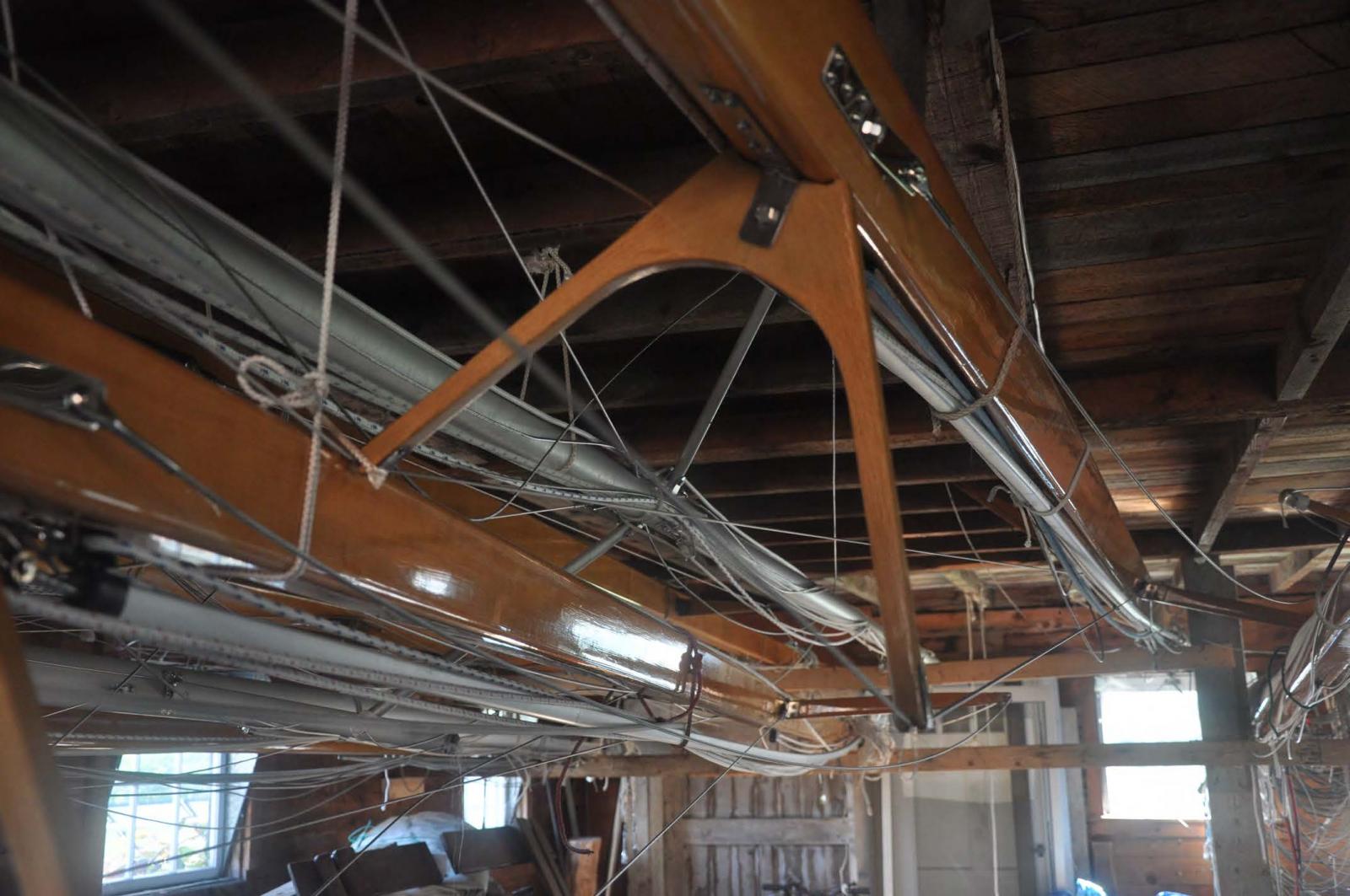
here are some views from the mast and boom as they hang in David's barn. He is currently storing 13 BHOD boats.
-
 Here are several booms; they are not all the same. In fact the 1970'ish boats switched to aluminum masts and fiberglass hulls.... I needed to combine function with look.
-
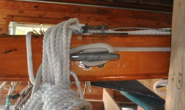 Here is Bittersweet's Mast. The cleat is for the spinnaker halyard and located here in the solid mast section adjacent to the gooseneck
-
 I shared before the idea that I would buy from Roger Cousineau a good working gooseneck made for vintage Marblehead Pond yachts. It has a brass insert that is embedded a good inch into the boom and will last a long time and avoid stressing soft spruce with screws and things.. I then added wings to get the look. To stay with brass cleats, I opted to use Wet Goose cast fittings. Hopefully they will age gracefully. Both Mast and boom are Sitka Spruce as is Bittersweet
Cam Cleats
I thought this was going to be impossible. I then took on the task of starting and realized that even at the large 1:6 scale the need to replicate a tear dropped, toothed gear is subjective. hopefully the 3/16" brass rods will age and suffice.
-
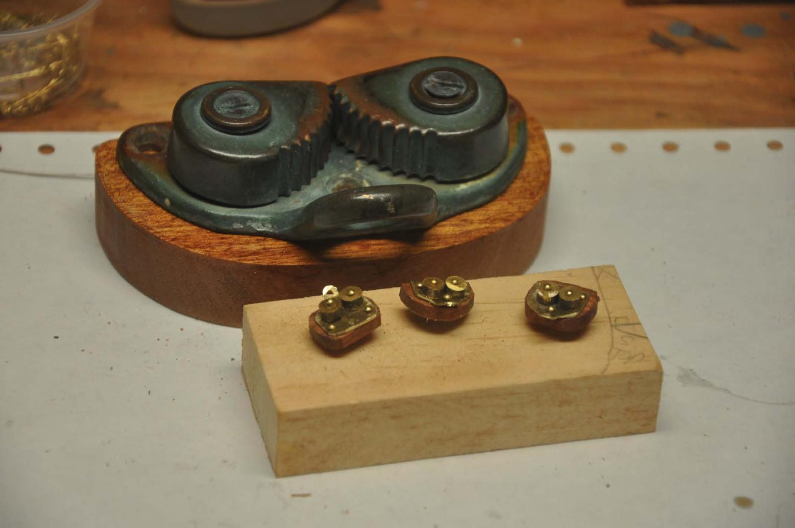
 Here is the challenge. The boat had only one cam cleat for the main sheet. David and I agreed to go to three and include the two halyards. They are safe user friendly and respect the classic design.
-
 I need to make the new bases for the real boat for the two new cleats. here one is under the existing cleat. I then worked through a proto type.
-
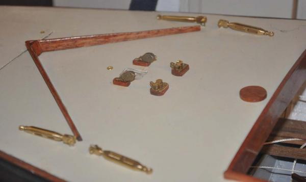
 Here I have all three made up. Don't look too close they are not identical....
  Their mahogany mini bases were were stained and varnished just like the real ones.
-
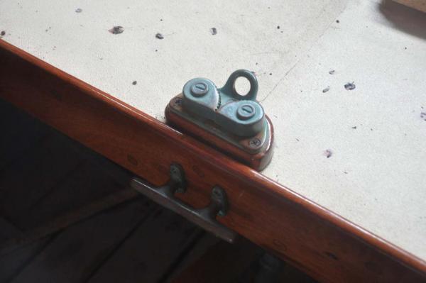
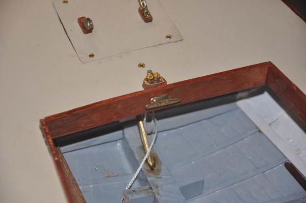 Here I have installed the cam cleat for the main sheet. I moved it a bit aft of the combing to leave clearance for the cockpit cover I may need to use for sailing. The combing cleat is used to secure the boom when moored or to tie off to a dock when docking. The boom crutch is not there yet.
-
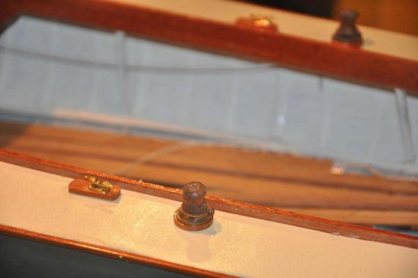
 Here I have installed both the stand up halyard blocks and their cam cleats near the mast. You can also see the turnbuckles are in place as well.
winches
I shared earlier in the log my attempt to get something made as a place holder. I am no machinist so I made the turned barrels of wood and tried aging with brown and green paint. I have a friend who said he would help make them in brass later.
-
 Here I have installed the side jib sheet winches along with the jam cleats. I have not made up the jib sheet tracks yet.
cheers
- michael mott, pete48, Omega1234 and 3 others
-
6
-
-
Pete
thanks for showing this. I am most interested in the method to size the forms to allow full ribs before planking. I look forward to following along. I also love your large collection of photos that show up on your logs.
cheers
- michael mott, Omega1234, pete48 and 1 other
-
4
-
Michael
I am amazed as i read this log. The solution of steaming has given me courage to think about possibly trying something similar. I need to figure out how to use wider and thinner planks on my hulls so i can consider letting the planking show through on the outside. Currently I sand the hull smooth and avoid the issue. Thanks for sharing. I look forward to watching and learning some more
jon
- michael mott, mtaylor, Piet and 2 others
-
5
-
Hi All
We have reached a fun stage. Here we look at the real fittings and figure our how best to replicate them+ . I am trying to use as much brass as I can, so it will age just like the real thing. A little salt water helps too I am told. we'll see.
At the same time, I am plodding away with details that make the boats sail and catching up with hull two. First example is to work on what can be a nuisance leak....the sleeve and rudder post. Here the sleeve and post enter the hull below the water line and effectively end at the stuffing box which is technically also just at the water line though inside. To avoid this natural leak, since I don't have a stuffing box ...... the attack is from both ends. I hope it works
-
 Here we go to the bottom side up and fill the gaps until the they stop draining with resin; it will take a few attempts. It's a bit messy but this is a working boat, so a little sanding and repaint needs to be understood as an ongoing item.
-
 Here we are right side up and again we fill the gaps, again a few times. I also filled a few slits in the plywood keel. the new floor support and a dip in the planking. All will get repainted. I hope we sealed it all up.
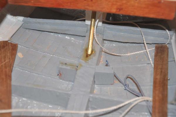
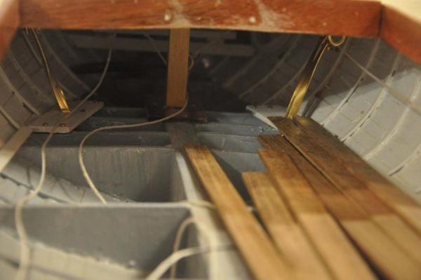
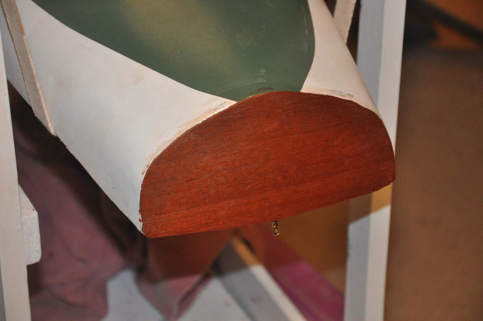
- The rudder post normally stops at the floor level in a stuffing box. The photo shows I took the rudder post and its sleeve and continued it up through the aft deck support. To do that the support is wider than real. My thought is that the larger support post helps hide the RC fitting turning the rudder behind while the boat is on display.
another fun job was getting some mahogany veneer and gluing up the transom on hull 2.
-
 there is no where to grab so bow up on a sweat shirt and several lead weights and wedges to hold the veneer down.
David and I discussed mahogany transoms and it being inside planking or aft of planking. On new cold form boat , he would build the transom in Mahogany and it would be inside the planks 1938- 50 ish would be the same...may be
-
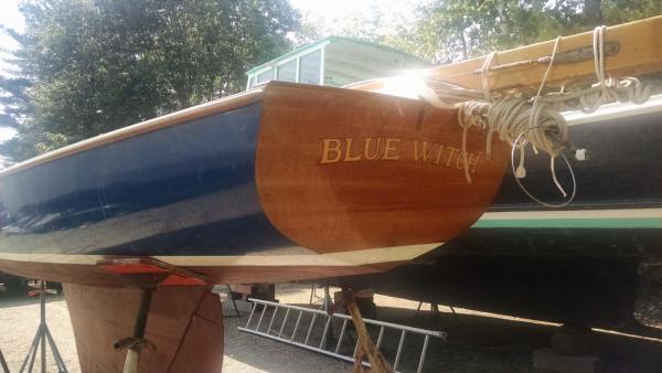 . here is a sister boat Blue Witch. She was reskinned also by Brooklin yard and note they added a mahogany veneer transom. I assume the real boat has mahogany under the new skin. This is the way I shall finish the model as I am also actually adding a veneer over a resin skin.
-
 Here she is with stain and one coat of varnish on the new transom....seven coats to go to get the right look.....I hope.I also need to bring the green water line around again on hit the sides with either white or green.
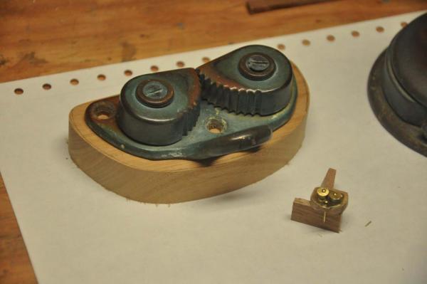
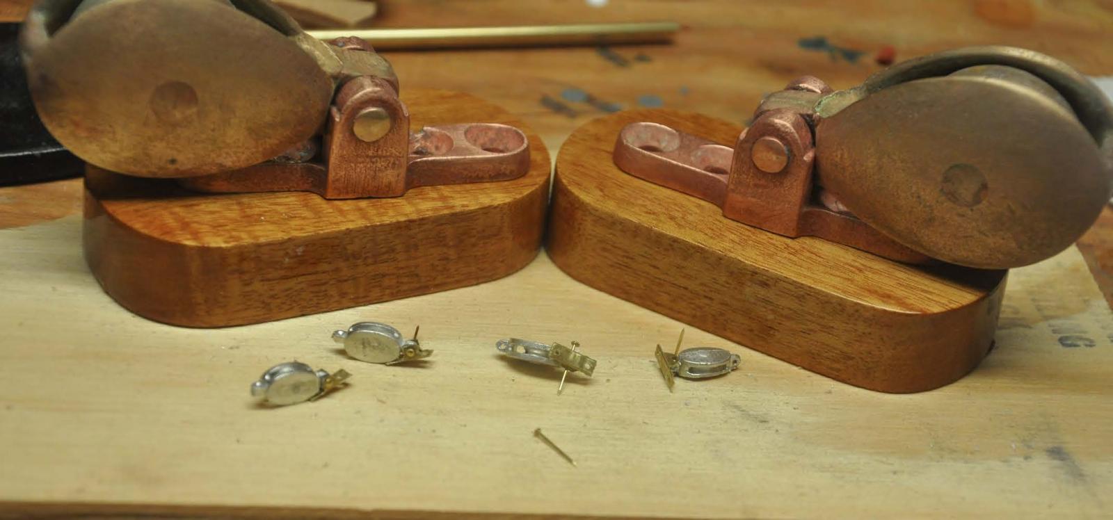
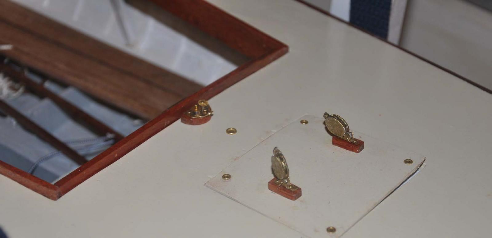
Lets start with the fittings. David showed me the old halyard blocks that were located below deck. We agreed to the new design to bring them up on deck and use new cam cleats to hold the halyards. The halyards could then carry through to a new forward winch that also allows handling the jib from a forward position. This design avoids leaning over and under to haul up sails...no fun at our age.
-
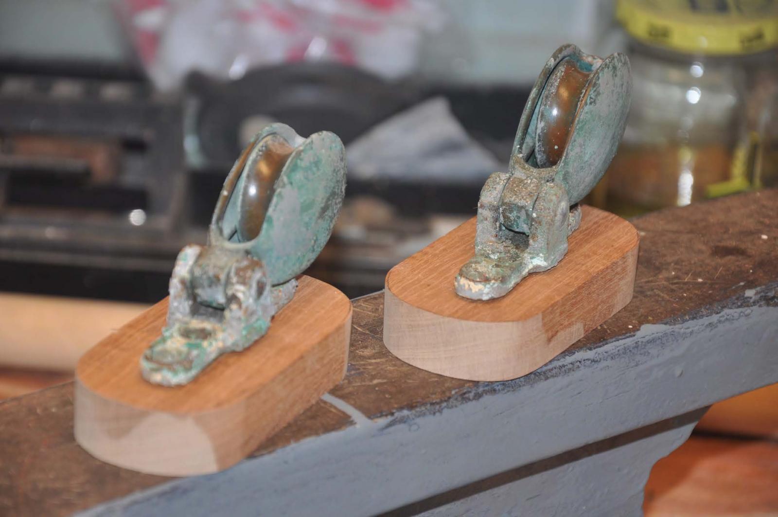
 Here are the blocks as they came off the boat. I am making new mahogany bases for all the new fittings on Bittersweet, so we shall progress together.
-
 Here I have cleaned up the real blocks and stained and one coat to the base. I was intrigued that the real brackets turned out to be copper. I also prepared the miniatures. I used 1/8" brass channel cut down and stropped blocks from Bluejacket.
-
 After a lot of thought on methods to get to an old bronze look with Bluejacket Britannia metal, I caved a bit. While visiting my son he showed me some bronze paint that goes on thick. I tried it out and for the moment this what I am going with. I may still add the bit of brown and green wash later, but these look OK only for now
cheers
- mtaylor, captainbob, Omega1234 and 4 others
-
7
-
-
Patrick
I thank you fully for your support. trying to make the model sail and also reflect the real thing is the true goal here. I find doing this coincidentally with David doing our real boat is a one time opportunity that I also relishing. We have our first association meeting in June and the pressure is on to be ready.
cheers
jon
-
Hi all
Well we are moving along and I thought it time to update our progress. As I am working both boats, I will be going back and forth a bit. In general we have progressed hull two along in a catch up mode. As I am working hull one, it take more time as I need to develop things like hardware. After I figure out what I plan to do, I usually have to buy more stuff. sound normal?
I make all the parts for both boats as I go. Most importantly I am visiting our neighbor David, the real boat builder as he is restoring the real Bittersweet. He has been building an sailing boats for 40 plus years, so I know we are in great hands. I shall show some pictures of her as we go along especially as it ties directly to decisions on this project. The first example is to understand the update to the class design to add strength to the mast via a second shroud and set of spreaders. This added strut and shroud does several things.
good stuff
- it sets up a truss for the lower mast that used to bend.
- it doubles security as to point load and sharing tension in a blow.
hard stuff
- it means doubling the connections to the boat. One method for adopting this upgrade to older boats is for the lower shroud to be attached to the mast just above the deck.
- The design revision that is applied to any new boats incorporates the double strut as a class standard. In the design they add a plywood bulkhead to rib 10 and grab it on either side for two chain plates. This point of connection relieves the point load on the floor in the old design. it also makes a very strong diagram at the mast. David calls it making us " bullet proof"
The 1938 design has one chain plate.
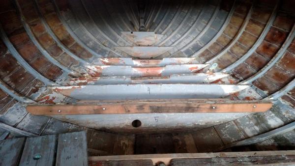
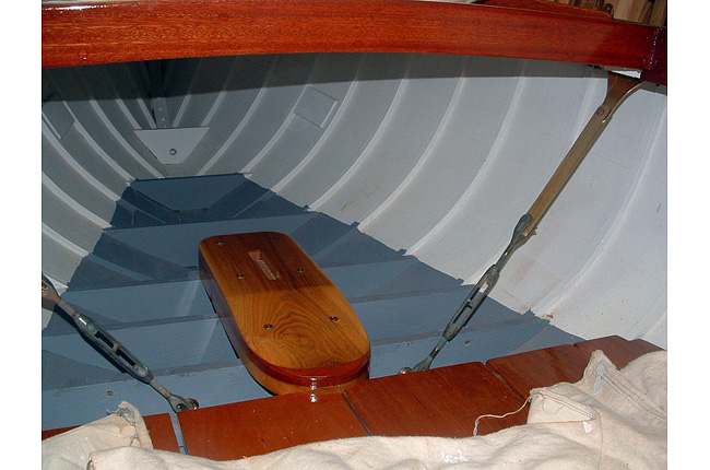
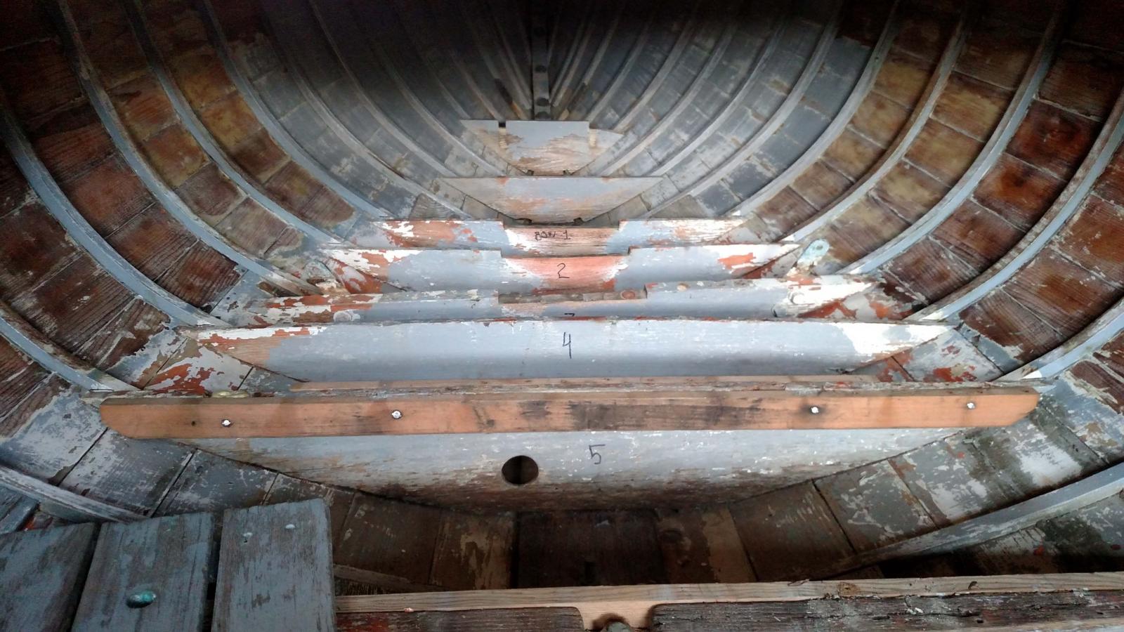
 Here is image from the web showing a nicely restored boat looking forward below deck. Note the nicely finished mast step, gray epoxy hard paint in the bilge, and sweet bronze chain plates. there is an option. put the turnbuckle as in the photo , or twist the plate 90 degrees, add a link and set the turnbuckle above the deck.
At the time I built hull one, the idea was to double the chain plates below, to twist them and relocate turnbuckles above the sealed deck. The load was being spread by a heavy floor plank on top of several floors ganging them together.. Therefore I proceeded to model that solution in hull one....Bittersweet junior.
 Here is how I built the model to reflect that approach.
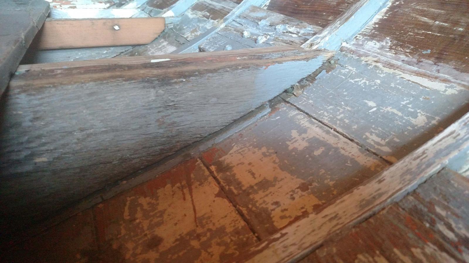
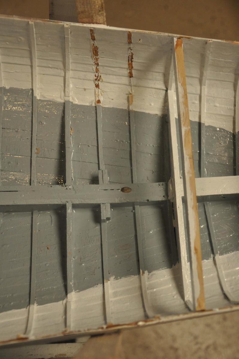
While reviewing the real Bittersweet, David [ the builder] found the critical floors were not reattached as part of the 2011 reskinning job. perhaps an oops.
 the two floors holding the mast step were loose with a gap up to 1/2 inch. wow! not too much was holding her together.
David progressed and I after discussion I decided I did not want to try to save the floors. Four had sister beams for attaching the old sole and both had many old fastening holes.
 Since we are changing the sole and all the new holes continue to weaken the old floors new floors are on order.....ouch $$$.
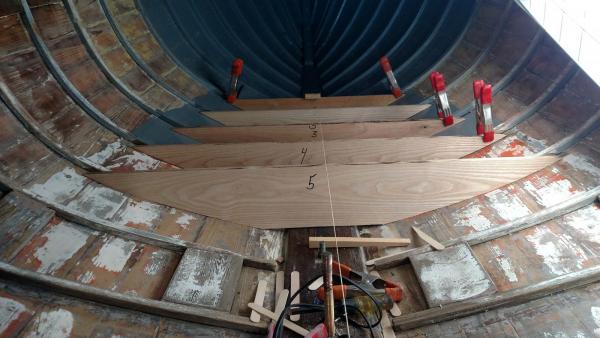 here is the progress. Isn't it great to see a real craftsman.
Bulkhead
David and I talked after a long Xmas holiday . After multiple ideas on better attachment of the floors to the two chain plates, we decided to go with the new class design and add the plywood bulkhead and attach the chain plate to that.
 I went home and immediately made the bulkhead for hull two. it looks right.
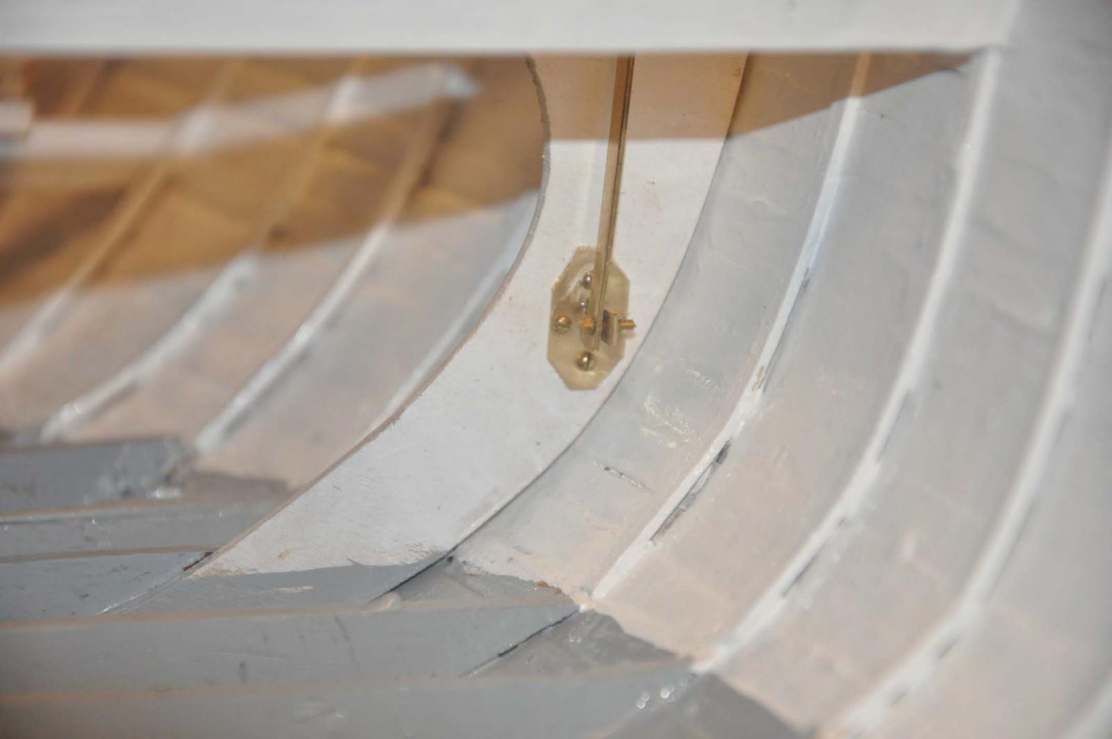
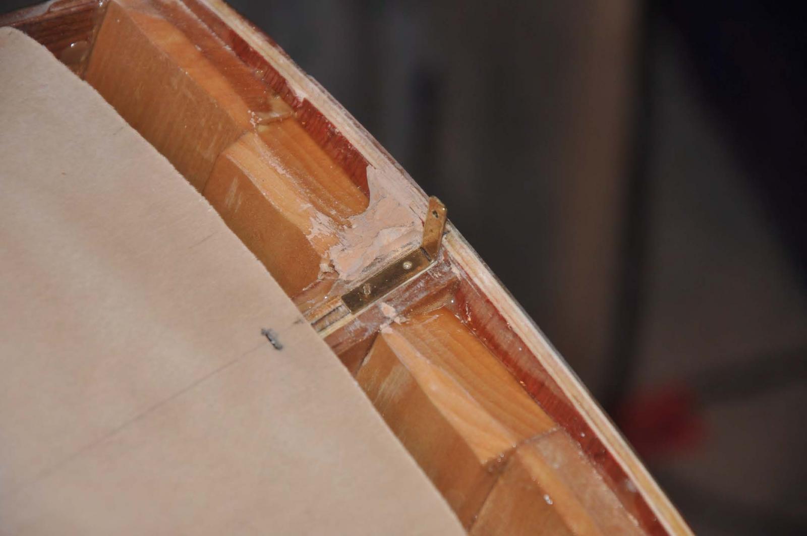
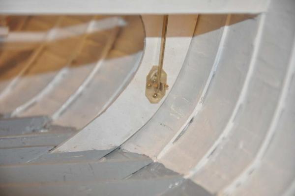 Here is is later after installation and inclusion of the chain plate bracket. I fear the new bronze braised brackets for the real bought won't come as easily. $$$$
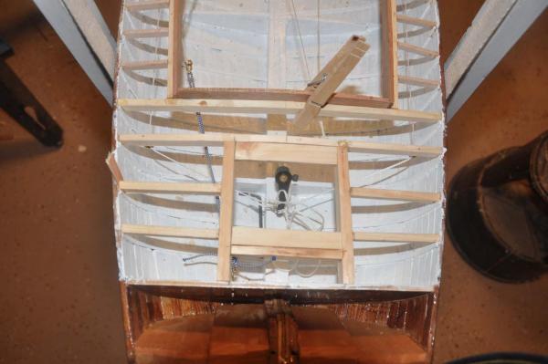
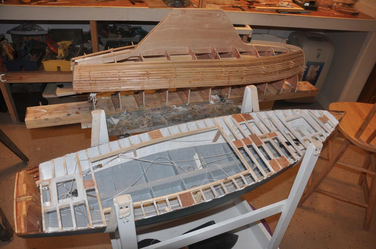
It was time to glass in the interior of hull two
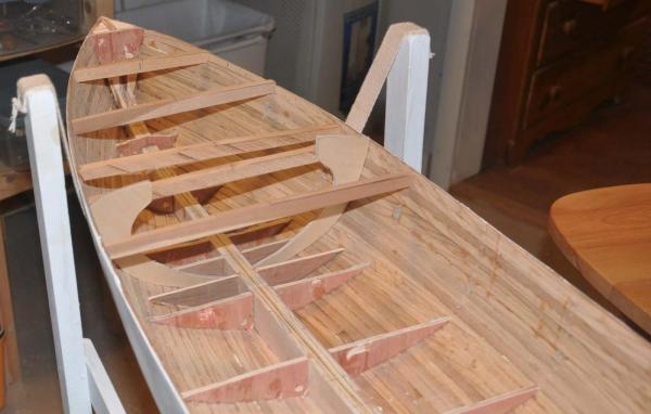
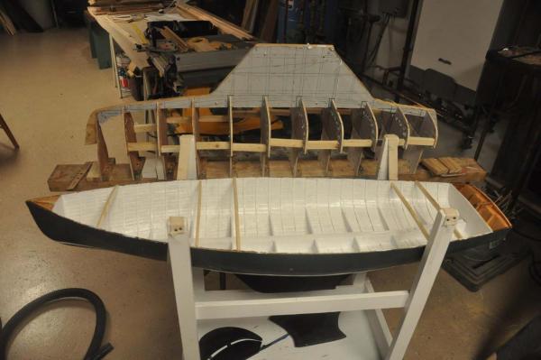
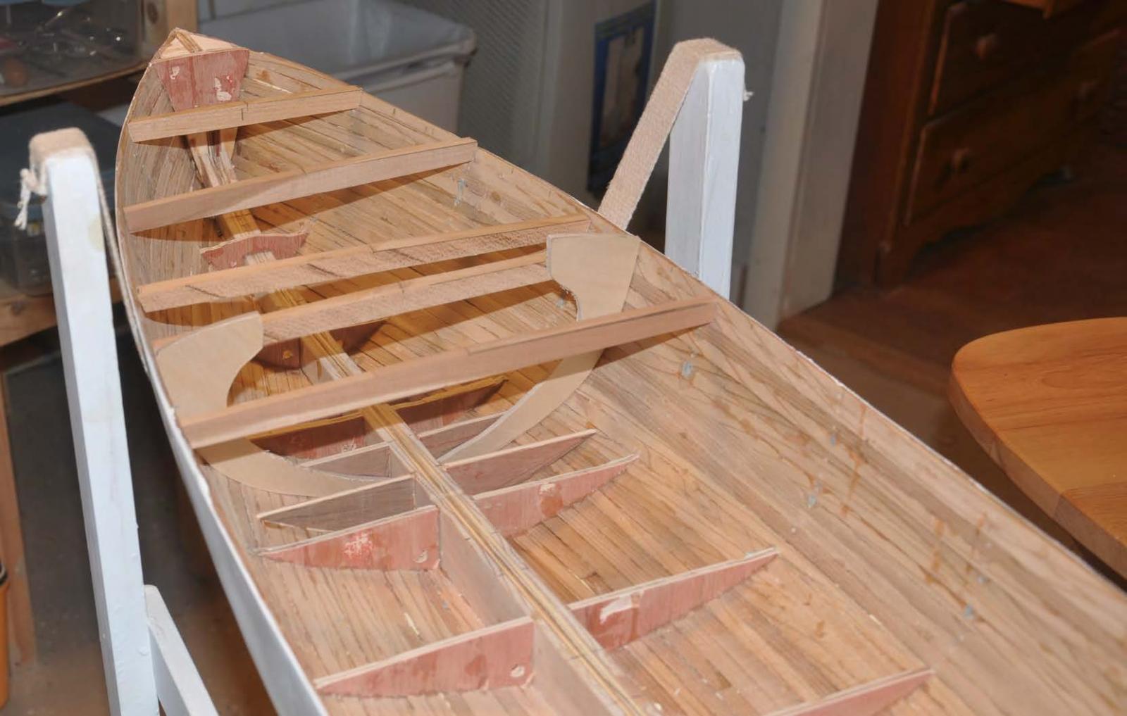
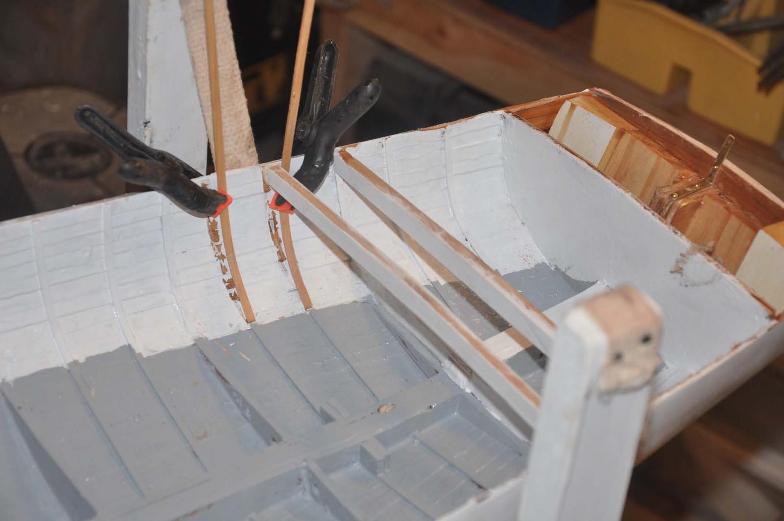
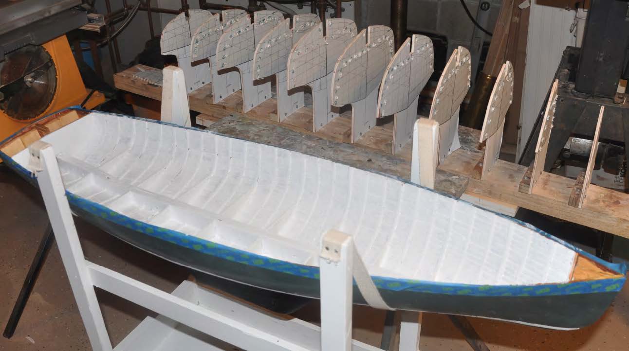
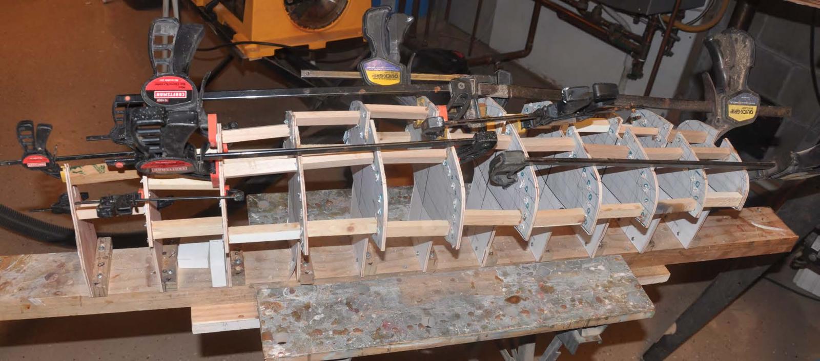
 .. here you see the difference from hull one...look at how many ribs I had to prepare since I did not put them on the molds.
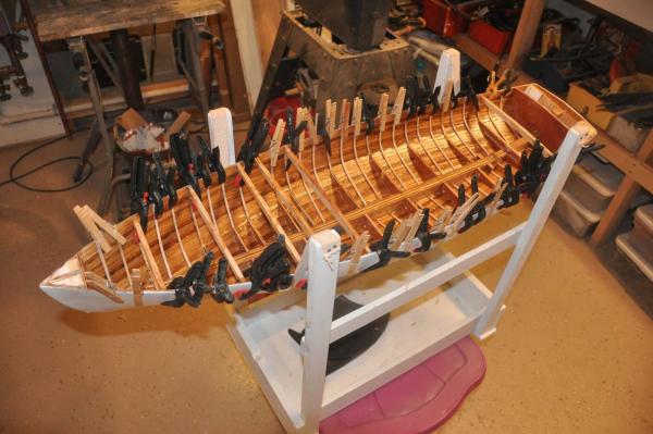 Here they are all in. I think they look much better and have adopted this approach for an exposed interior going forward
Oh well here is an oops. not the first one I assure you all
 setting the ribs into the resin is a good idea, but there is risk of movement, and here we have two that are off. They go where the deck beam crosses for the end of the cockpit so I had to knock them out and replace them above the future sole.
 here I have added the deck beam and realigned the ribs to suit. In this hull I will have a larger cockpit which means this frame is the aft end.
cheers
-
Hi All
We flew home from Florida and arrived in the middle of a snow storm....yippee winter is here.
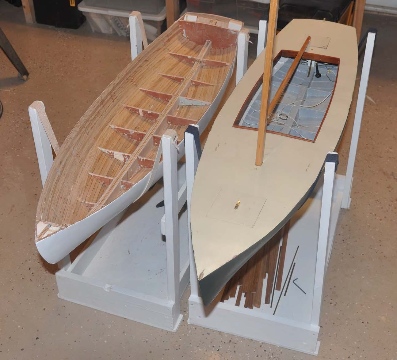
I got a few days in on the boats, so here is progress as we close out the year. I had to build more strap stands. they will be color coordinated Later. Hull two is off the molds and rough sanded inside. Hull one has mahogany combing and hatches figured out.
 Please note the cleaner inside of hull two. I left out the 1/32" sub ribs under each form and that worked out well.
more later
cheers to all
- Fright, pete48, popeye the sailor and 3 others
-
6
-
Thank you everyone for your following along. I will do a longer post after the holidays but just wanted to share status as we take a holiday break.
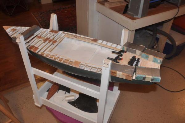
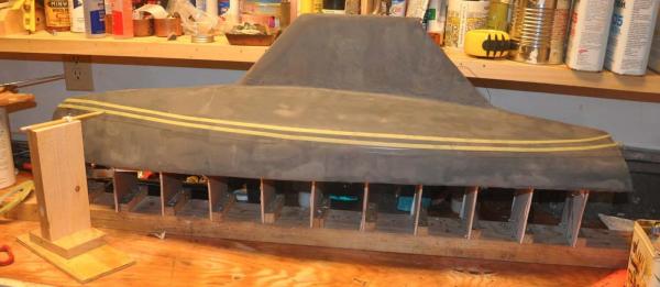
We have had very nice fall weather here in Maine, so I was able to rush a bit to allow me to spray paint the bottom on hull 2 outside. Once it is too cold for outside spray, I am reduced to normal paints. I just like that first construction coat or two to be good old rattle can enamel. So I spray and carry her inside to harden up. Then out again for coat and back in side to dry.
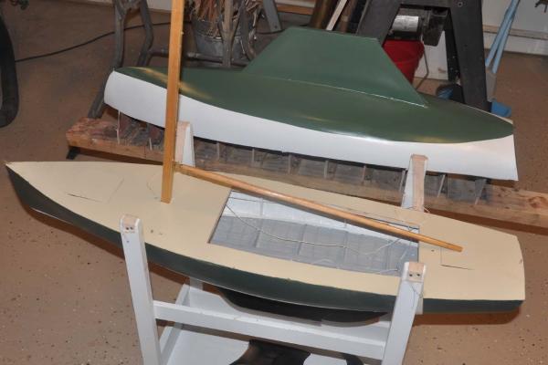
I got the second hull ready and painted. Please note she is not yet named. I chose the paint scheme of my boat bittersweet prior to the re-skinning. Her photo pre-skinning is early in this log. I also plan to upgrade this hull with a mahogany transom.
The masts and booms are also done, so I set one in for the photo. I am working on the spreaders and other details that I shall pick up in January. That all needs to be completed off the boat. I also have received the first sail.
now let's all enjoy the holidays
cheers
-
Hi all
I thought I needed to update the log as progress is being made despite many interruptions. Progress is moving on three parallel fronts.... hull 1, procurement and preparation of spars, sails etc and hull 2. I am working on all three so please excuse some confusion as I go back and forth. We must remember this build is meant to include two boats, so they can race.
Ok last time I left out a step or two on hull one interior.
1. After cleaning up the interior I needed to install ribs. To get the best look I chose to use 1/16" bass because with ammonia water it was easy to bend and shape. In scale it should have been 3/32". So to get the right look, I chose to mount them proud onto the coat of sealing resin. This method gives more of a shadow and makes it work. A problem to resolve is the building method included placing a 1/32 strip of birch plywood on each form. These sub ribs were separated by tape so they would easily come off the form and remain in the boat. They are at each 3rd rib line.
2. There are two problems or lessens to consider in hull 2.
a. Oops the boat is 1/16th too wide because I did not take consider the 1/32 sub ribs.
b. The sub ribs are located every 3rd rib and are 3/16" , just wider than I wanted for the ribs. I ripped some 1/32 strips later to compromise and they came out OK. see painted photo.
-
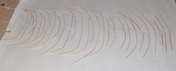
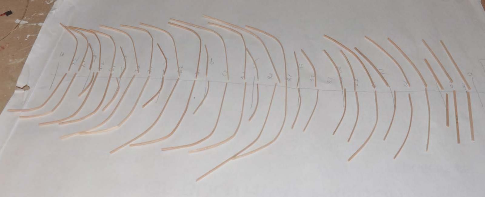
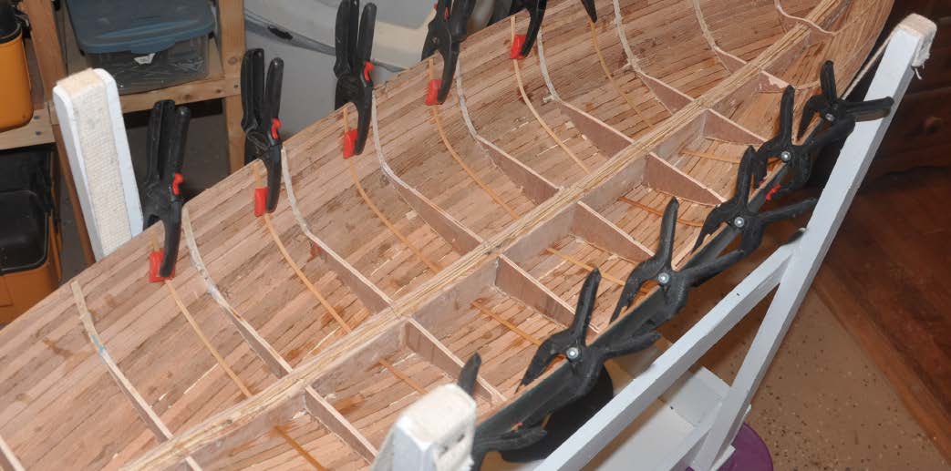
 here the wet ribs are set at one third points betweeen the formed ribs and left to dry.
 -
 here the ribs are marked and stored until the inside is coated in resin
 -
 here I have coated the inside with resin to seal the boat . i laid the ribs on the resin to accentuate the shadow line.
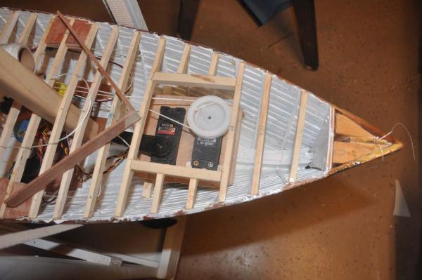
3. My first attempt to place the servos was to consider a removable cigar box approach. I assembled the items and then set in the box. It did not take long to decide that was not the way.
-
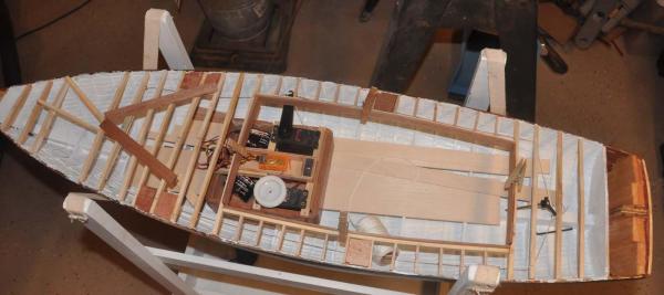 all RC equipment to be set and secured when sailing then removed. I chose not to pursue this option at this time.
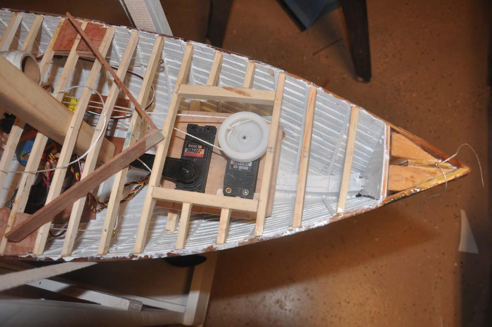
4. The only place that gets wet when sailing a pond yacht is typically the fore deck. Thus one does not penetrate that deck ....after a lot of thought I decided to break that rule and make a full forward hatch so I could bury the servos and stuff.
-
 here is the new foredeck hatch for access to servos.
5. The rudder also needs access, so a smaller aft deck hatch is made.
-
 here is the aft deck hatch for access to the rudder.
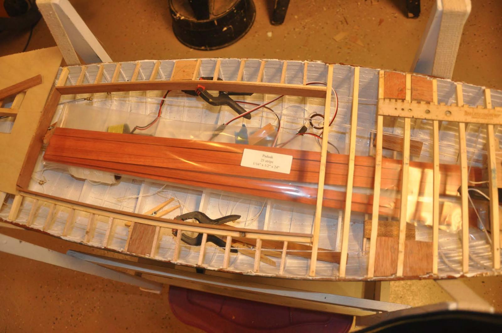
6. Several folks at the NRG conference recommended to me that I should use Paduak to replicate teak. I bought it and yes it is beautiful. Here it is resting in the boat. I will think more about this as my boat is really teak and I have that material. This issue is not solved yet.
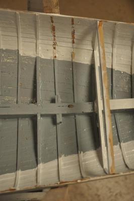
7. I was up seeing my real boat and found that we are using special hard bilge paint which is gray. Even though most is below the teak sole, I chose to paint it as it should be. The 3 center sole boards should be removable for bailing and I need to do that too. It will be nice when the right color is there to greet us.
-
 here you can see the common progress. As I was painting out the bilge in hull 1 and I was starting hull 2
8. Completing all the hardware blocking under the deck and building the six chain plates is the final activity before adding the deck.
9. For the back stay I chose to put a simple L bracket on top of the keelson and screw and epoxy it in.
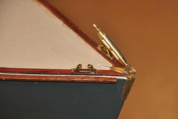
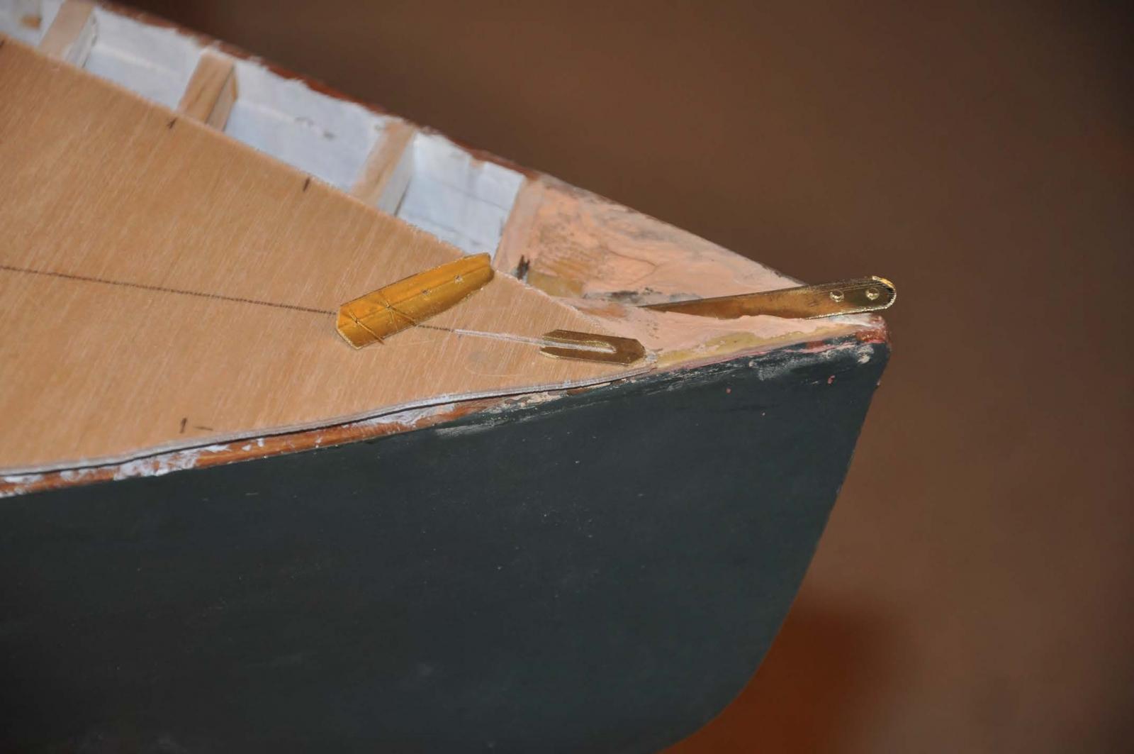
10. For the head stay I need a stem strap. After a lot of thought,I chose to cantilever a brass bar. It will be in a bed of epoxy and have the deck plywood holding it down. I then glue down shaped brass flanges on the deck and pin a brass angle on the bow completing the fitting . I will show it against the real thing when it is all installed and cleaned up.
-
 some day I will learn to make a jig and silver solder a strong fitting. lets see how this looks though.
11. The shrouds plates were really hard for this boat.
- The normal design is a single shroud bolted to the floor. The option is to have the turnbuckle below deck and only the shroud penetrating the deck or to install a twisted bronze chain plate, bolted to a link through the deck and have the turnbuckle above the deck.
- In the 1970's the new boats have aluminum masts and a double shrouds. The approved class design allows upgrading the wooden boats to include this added shroud. Its purpose I will show in a later post. For now I am replicating my real boat. we are simultaneously upgrading it by adding this second shroud to stiffen the lower mast.
- In my boat there is a OAK plank securing the floors before and aft of the shroud to average out the uplift. There will be two twisted bronze bars with links and that is what I am doing. A big lesson learned.....I learned that I need to sort all that out next time before I build the deck frame . That way I can get my fingers in there and make the actual bolted connection etc. I needed to use a copper wire and that I bent to hold it down. Fortunately it will not be visible.
12. The after deck is now glued down with epoxy to the deck frame.
-
 here I and securing the after deck..
Hull 2 starts
13. Hull 2 can start now we have the building board. Reusing the marked, labeled station blocks , screw holes etc. meant I could install all the forms in minutes......nice re
13 a here as the forms are all set we can see the painted ribs on hull one. note the issue of the bent fomes in the last post. I needed to add double braces to fix it.
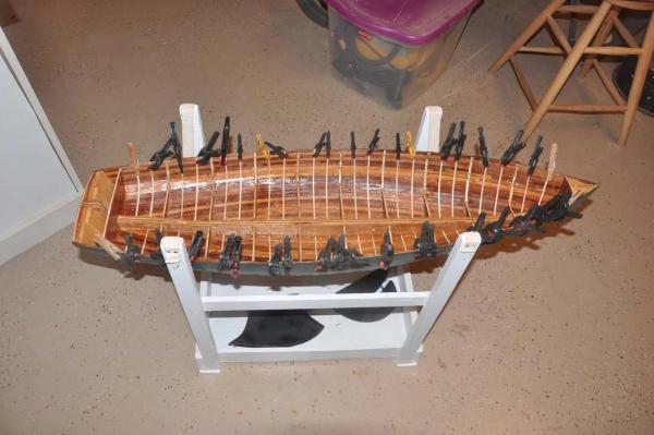
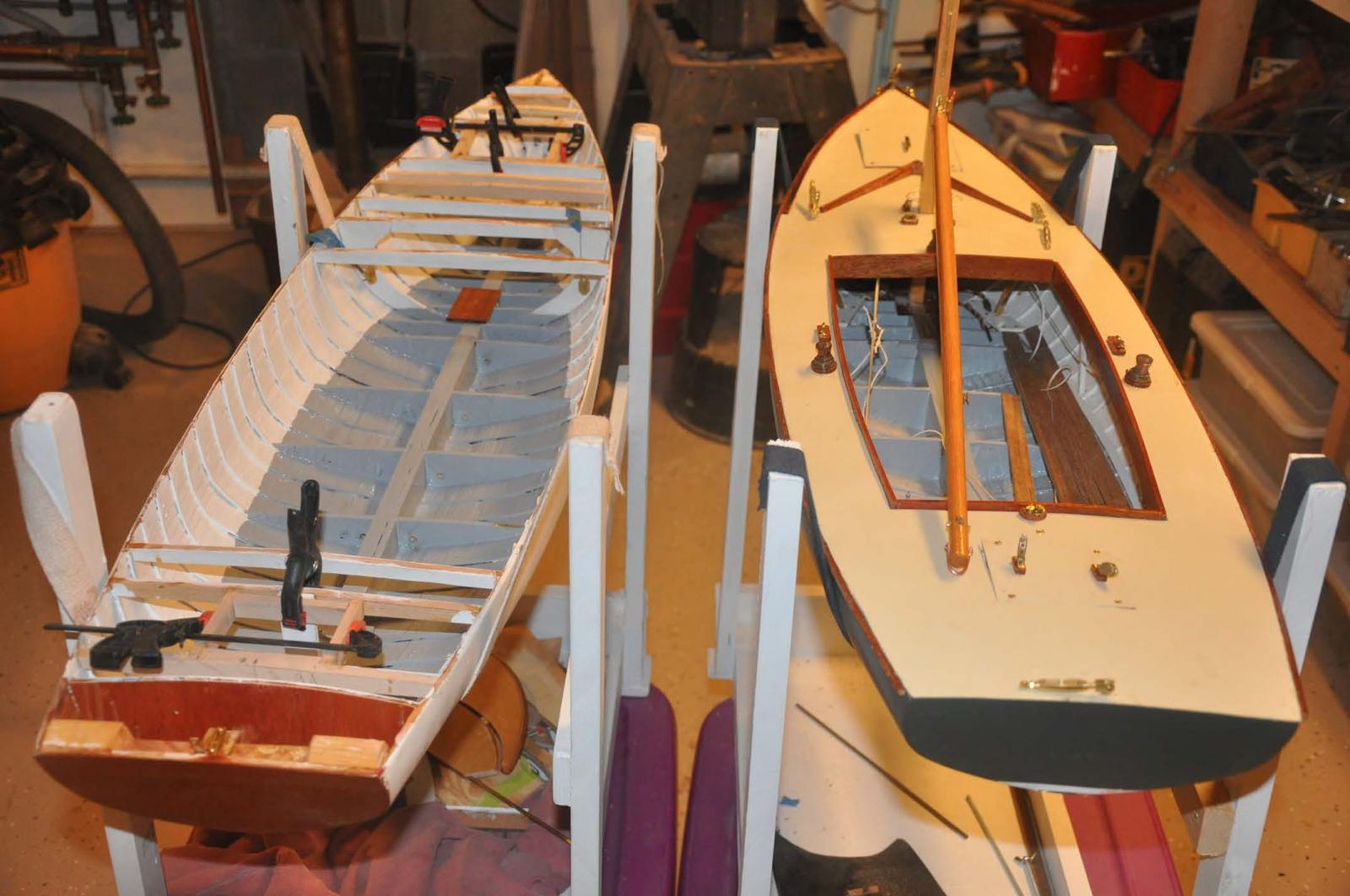
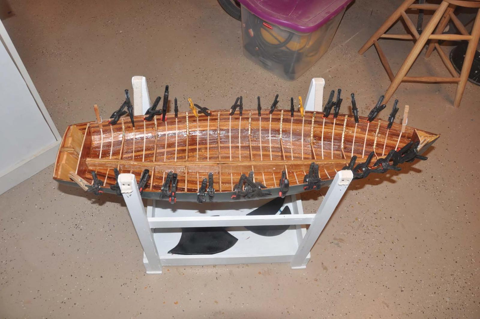
14. Here we are with all the planking in place and rough sanded. She is resting next to CHARLES NOTMAN, the downeast schooner I built last winter.
15. Here she is next to her sister getting her 6oz glass fiber blanket
16. Here we are with two coats of resin.
- Fright, avsjerome2003, michael mott and 5 others
-
8
-
-
Hi all
I wanted to update as we are heading into more holiday breaks. In general I am proceeding to figure out how to build the first hull and simultaneously start the second hull.
This is a procurement stage.
I have been successful working with a local builder of BHOD's to copy drawings produced as recently as 2006 for building a new BHOD in Maine. These drawings add many details that will be important. also I am field measuring as one of these first 2 hulls is indeed intended to replicate my real boat. I will identify a few examples as I get the assembly of the items as there are variations.
So what do we buy and what do we make?
1. Masts and booms....I bought Sitka spruce blanks. It is accurate for the class and wonderful to work with. I have used it on my previous boats too.
2. Planking: we are back to ripping down clear cedar to 5/32" by 5/16". A little more care and the results are a little better. Practice is important. It is still too much load fo r the mini table saw and I need to consider that aspect too.
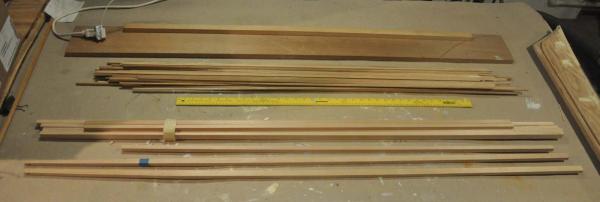 here I have shaped two of the masts and inserted the brass main halyard sheaves. I have also stockpiled the planking for hull 2
3. Mahogany...I am buying Mahogany for work on my real boat and am using some scraps from that. I also found some 1/8" craft wood strips that is perfect for cockpit combings, cleat plates, splash board, mast step etc..
4. Teak is an upgrade option included in many if the newer boats. My real boat sole is needing replacement, so I am upgrading it and thus this model needs teak. Several people have told me not to try to cut down teak. I may anyway as I have scrap to play with . In the mean time, I found Jason Clark for Crown Timberyard and he recommended and is providing so Paduak for the sole flooring.
Hardware for traditional design
these boats are alternately rigged with traditional bronze of the newest high end Harken fittings. there two hulls will be traditional.
5.
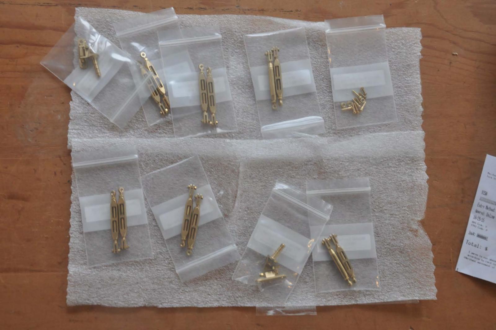
 Gooseneck and Turnbuckles: they need to work, so I went to a real pro Roger Cousineau. The fact he was a Mainer before relocating to Florida is just that much better. He remembers the BHOD class well and was helpful getting sizing right. I will need to add wings to his goose neck and will discuss when I do it.
6.
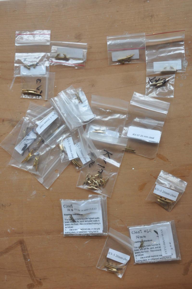
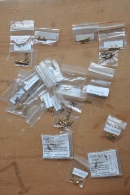 Cleats and chocks. I am trying to stay in brass so that I can then treat all to get that 40 year old bronze look. Al from Ships N things sold me several sizes of the Wet Goose brand and they really look great...but shinny.
7. Winches and CAM cleats.....for the traditional look, I am still working on it...see mock up winch earlier post. this will expand to include Cam cleats for main sheet and halyards. little gears I guess
8.
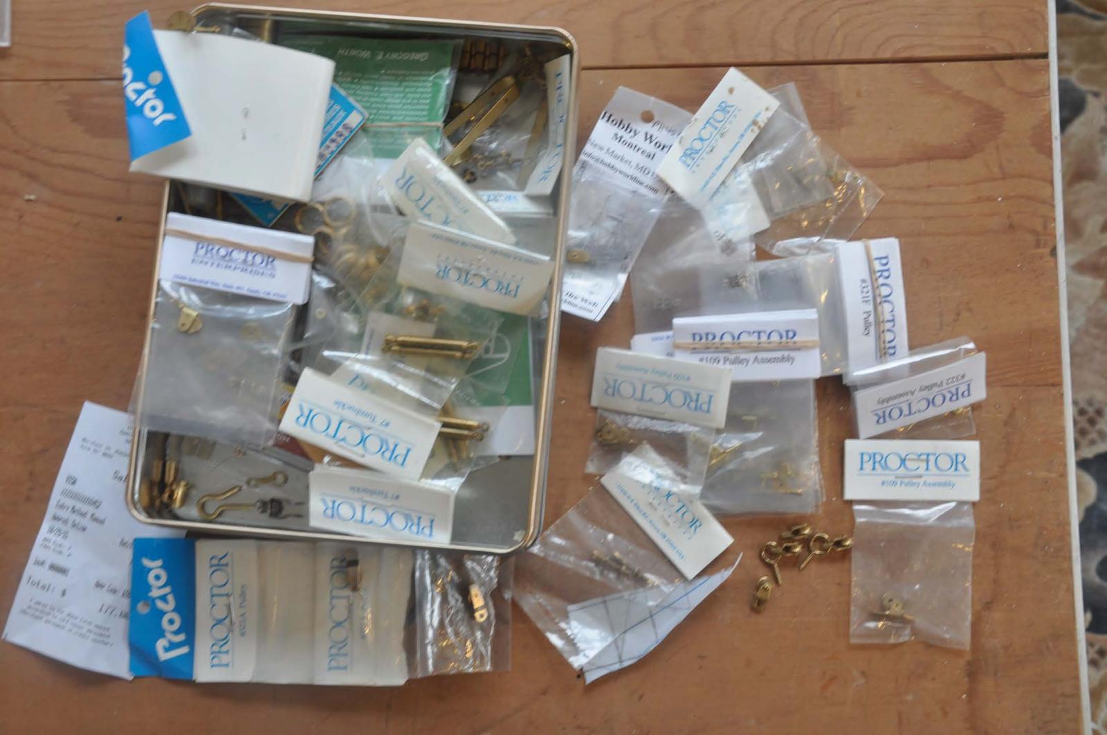
 Sheaves. We have two: one main halyard and one mainsail out-haul. They are proctor airplane sheaves.
9. Blocks: here we have two sets.
a. For the running rigging I have a combination of the fair-leads and a smaller proctor ' airplane pulley" . The idea is they will mostly be under deck and be actually sailing the boat.
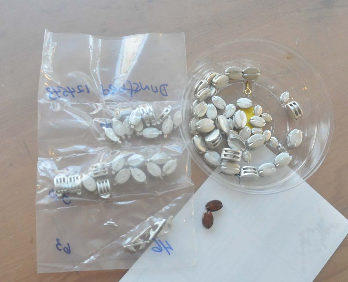
b. For the visual lines like halyards, jib sheets etc I have a combination of Bluejacket blocks that I shall paint and wash for affect. They are replicating the shell blocks of classic design.
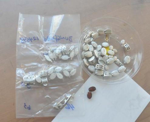 here i have Britannia metal to deal with. I will be painting brown and then washing green to get the look ....I hope
10. Stem Strap...this is a critical piece as it takes the load of the fore stay that is doubling its duty as a jack stay for the jib. My first plan to be sure we get sailing is to use a strong eye for the stay and smaller eye for the jib clew and then the strap is more for show. Ultimately I need to learn to solder a strong combined double eye and bent channel to complete the assembly
11. Sails...I have made my sails for the old schooners and small scale using muslin. One option for the 1938 sails was egyptian coton but they quickly went to Dacron. Modern sails are all Dacron with a higher tech revised class design, and that is truly the norm. This time I am trying to have race boats that look good and also perform. Rod Carr makes great racing sails for many classes in the AMYA and was gracious to bend a few norms to make sails for us in scale.
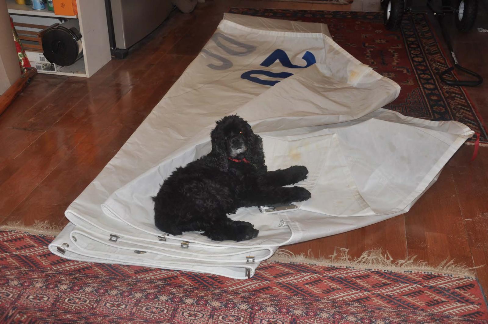
 here my second mate is helping me as I draw up and then scale down the sails for the sail maker. I will have a whole post on this issue as there is much trial and error going on.
12.
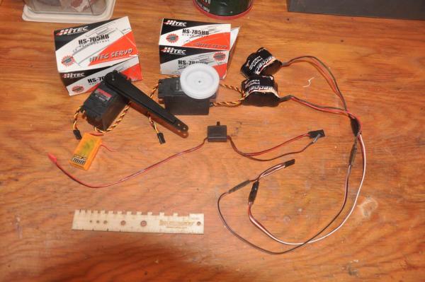 Servo's and controls. I am no expert, but following the lead of others as well as a little success with my other sailing, I focus on using Hitec sailing servo with 3.5 turning drum on the sails and 90 degree swing for the rudder. I like to use two batteries harnessed, to allow weight balance and removability for recharging. There are many options foe receivers and radio equipment.
13. ballast...this will be a long story for future posts
14. tracks and carrs etc. like bales and other misc i will make most of this from brass stock and rings
progress
 here was a fun day. I have removed hull one from the molds, added the ribs cleaned it up and painted out in white. I simultaneously progressed resetting the molds on the building board for hull two.
 Interesting issue. I bought 24 x 48 sheets of Luan, birch and fir plywood for these builds. I formed up hull one right after bringing the supply home. Sitting around for a month or so there was a slight bow in the luan that did not come out as I reduced size by cutting the individual molds. To fix this I had to add two more rows of braces to square up the molds.
- mtaylor, pete48, captainbob and 4 others
-
7
-
Michael thanks...FYI I lived in Edmonton for a year and truly loved it. I am still an Eskimos fan
Mike thanks.. I visited Switzerland a few times and wow...it was gorgeous too.
I am learning too as I quietly review both your building logs. this big scale is daunting as the fittings need to look good but also in some cases work.
cheers I am off for a bit
- Omega1234, mikegerber and mtaylor
-
3
-
Milestone..ready to remove from the building board and mold!

During the past few weeks we have been starting fall clean up, attending the NRG conference in Mystic, and trying to get progress on hull one before travelling. I just made it...sort of any way.
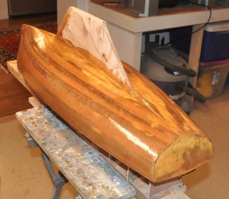
Here is the process I followed to get a rough sanded cedar hull smoothed up, fiber glassed and painted. During this time we need to design and install the running sailing rudder and keel systems as well.
-
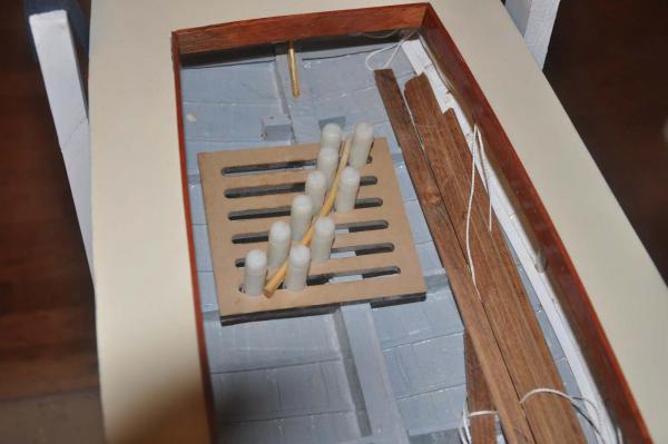
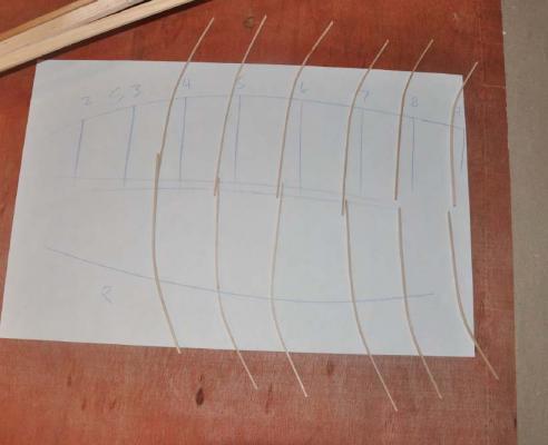
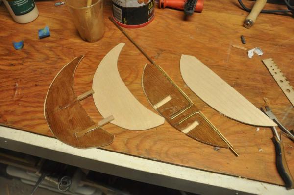
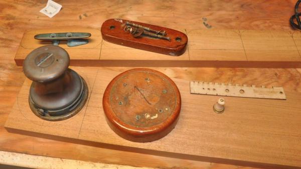
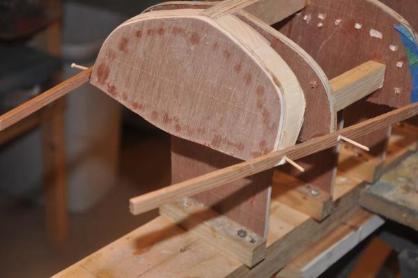
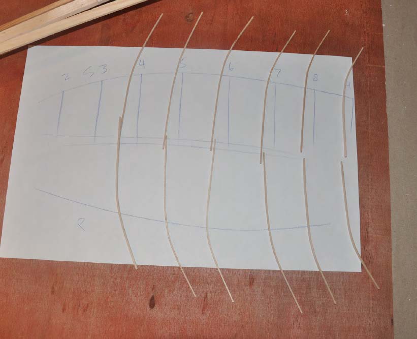
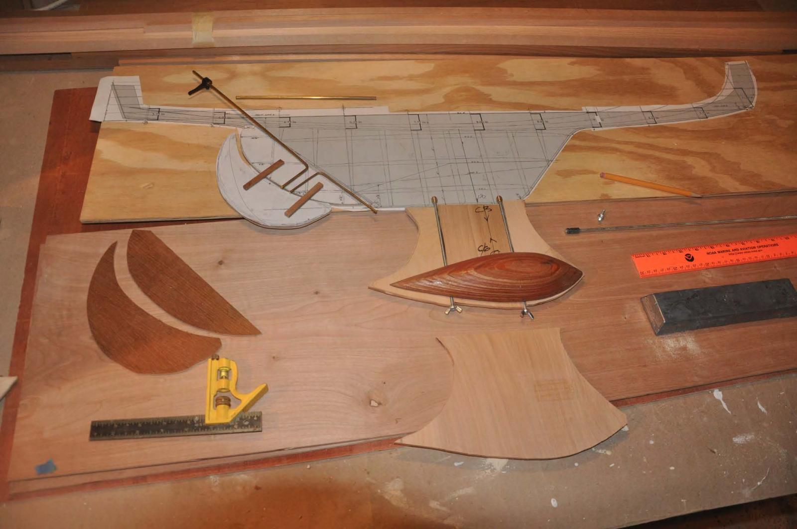
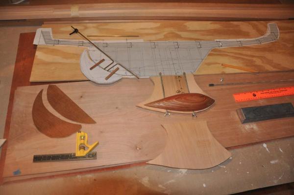 Here I have laid out the proposed display and sailing rudder as well as the sailing keel. I am not following a design but on this proto type making the first stab using former experience and a few principles.
- the rudder. the sailing attachment will use wood peg inserts into the display rudder, so unlike the Notman schooner,[ my first attempt] there are not two brass rods permanently projecting aft. During the building of this proto type, I feel the use of cedar for the ' pegs' was wrong and the next one will be hardwood for strength.
- the keel. first I have to calculate the center of buoyancy and mark it. it was 7/8 inched behind station 5. second I needed to understand the center of gravity for the intended keel weight. I knew from a marblehead design bulb that the CG of the carved wood mold in the photo and lined it up under the CB.
- The weight. This hull only displaces 8-9 # of water. That almost cancels out with the full weight of the boat I suspect to be about 5-6#.....we'll see. A marble head displaces a few more pounds.
- The issue for me is overturning not matching the waterline. So here is guess work that will sort out next summer with sailing and most probably adjustments. I have a classic pond yacht which has 10# lead for 50 inch length and 800 SQ IN sail area. The depth is about 11 inches down. My Marblehead pond yacht had 10# about 15 inches down and also 800 SQ IN sails, This boat is 42 inches but carries 850 inches of sail if I build them to full scale.
- all three items will be in play
- sails may need to be cut down
- lead keel weight will likely be reduced
- position of weight below boat may need to be adjusted
-
 here we apply epoxy glue for the brass rods internal of the rudder. I set the outer 1/16" ply wood skin at the same time making the rudder 1/4 thick. This is clearly a compromise as the design has a very sleek rudder that I can not replicate as it needs the extension to sail.
-
 here we go. I had used water putty on the cedar for final faring before glass. at the NRG session I was advised not to do that because the ate putty is harder than soft cedar and it actually could have cupped....I will reconsider next hull.
-
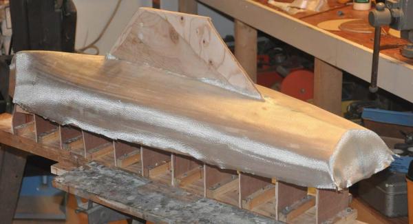
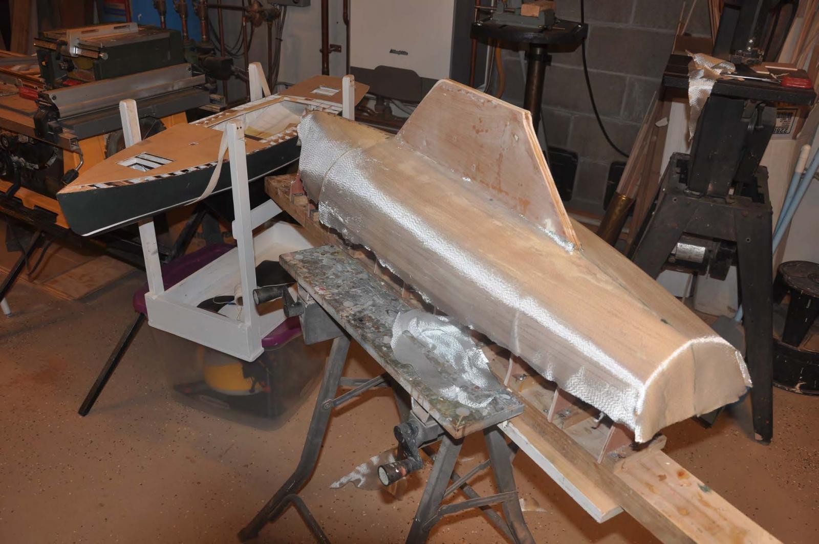
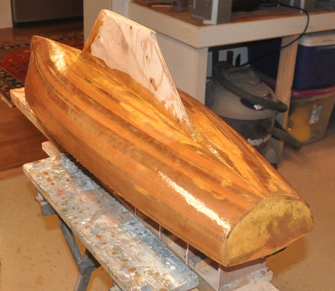
 Here is first coat of resin over 6 oz glass.fiber. I did three coats and vigorous sanding between.I chose not to do the keel with fabric as it is plenty strong. I did a coat of resin only.
-
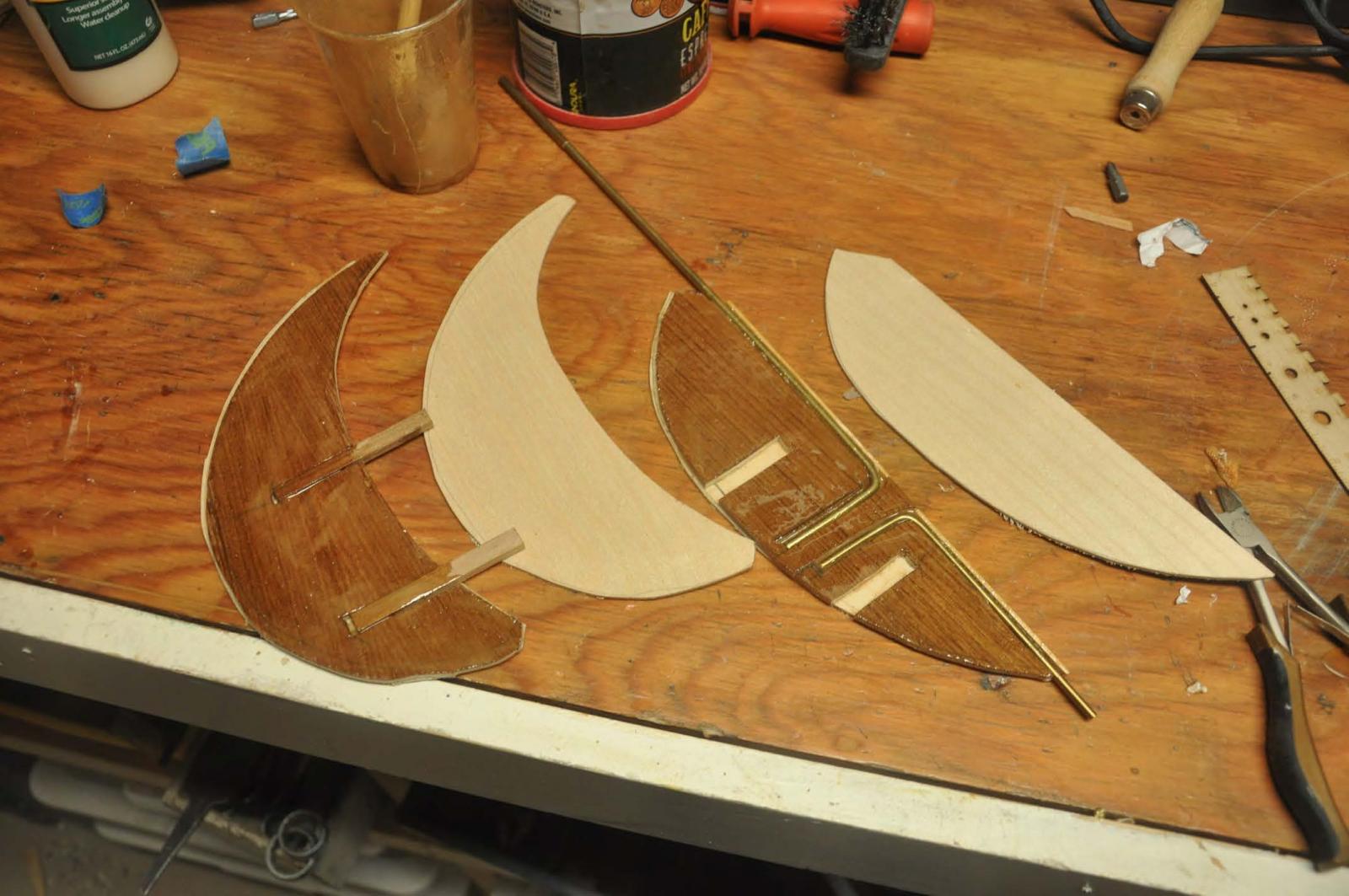
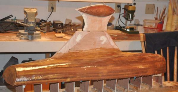 here is the first attempt sailing keel set on the real keel. I chose 1/4 OD brass insets to accept No 8 threaded rod. I assume the weigh will be leass and that size comfortably stays within the keel without too much stress. I chose not to glass the keel itself but may review that on the next hull if this become a weak point. Unfortunately I had cut it out before aligning the CG to the CB and it rides forward a bit. Once we figure it out this sailing keel will be reshaped to better compliment the form.
-
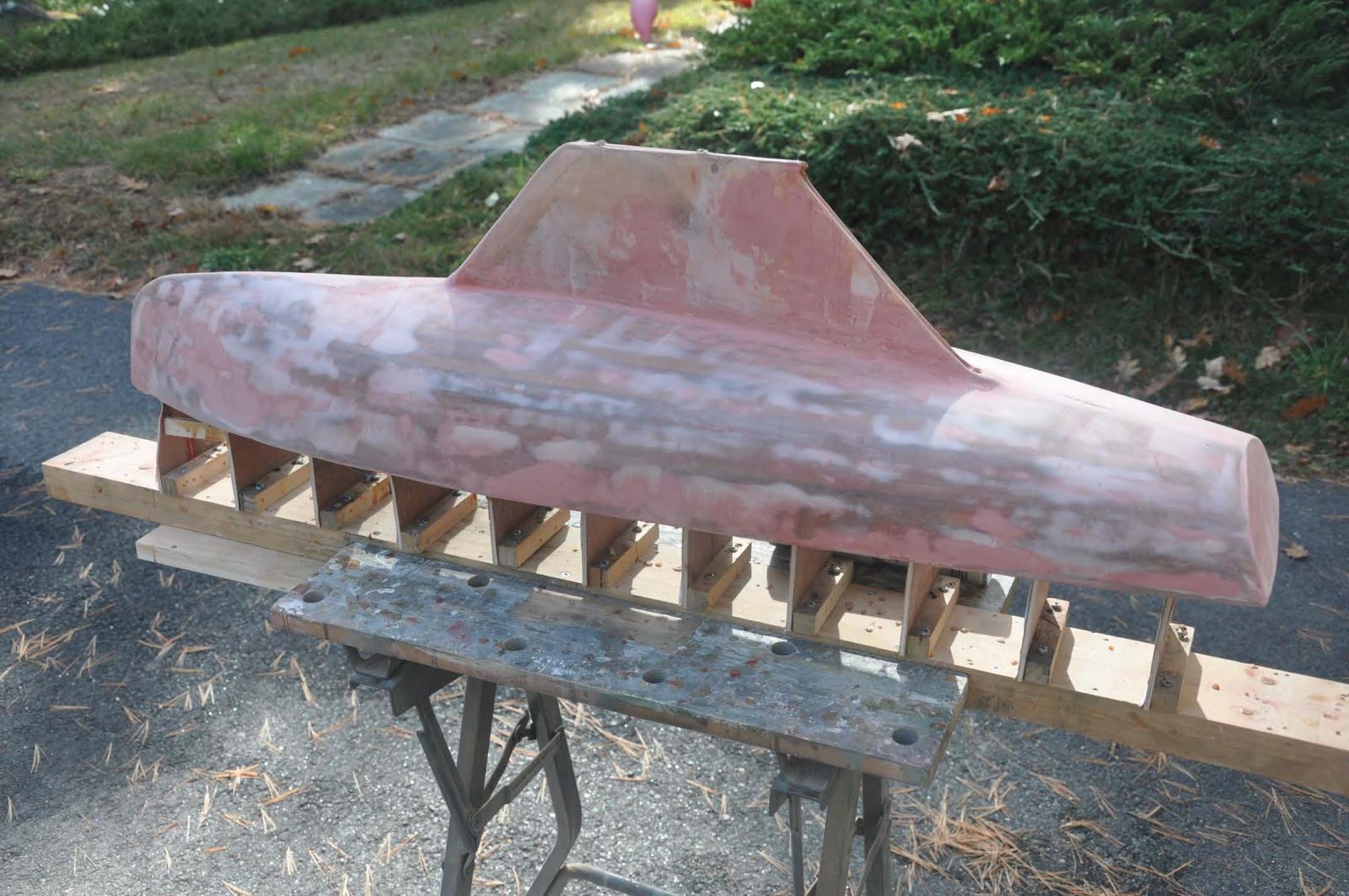
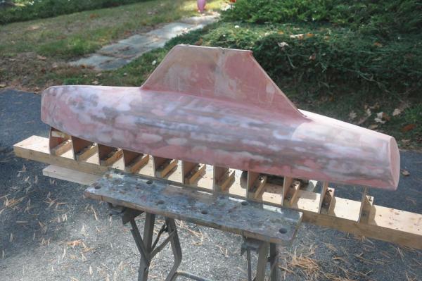 here is bondo on [ light gray] and sanded and finish puttly [ red] on to fill all pin holes and scratches. I stopped at 240 paper, pros go on to 400 grit.
-
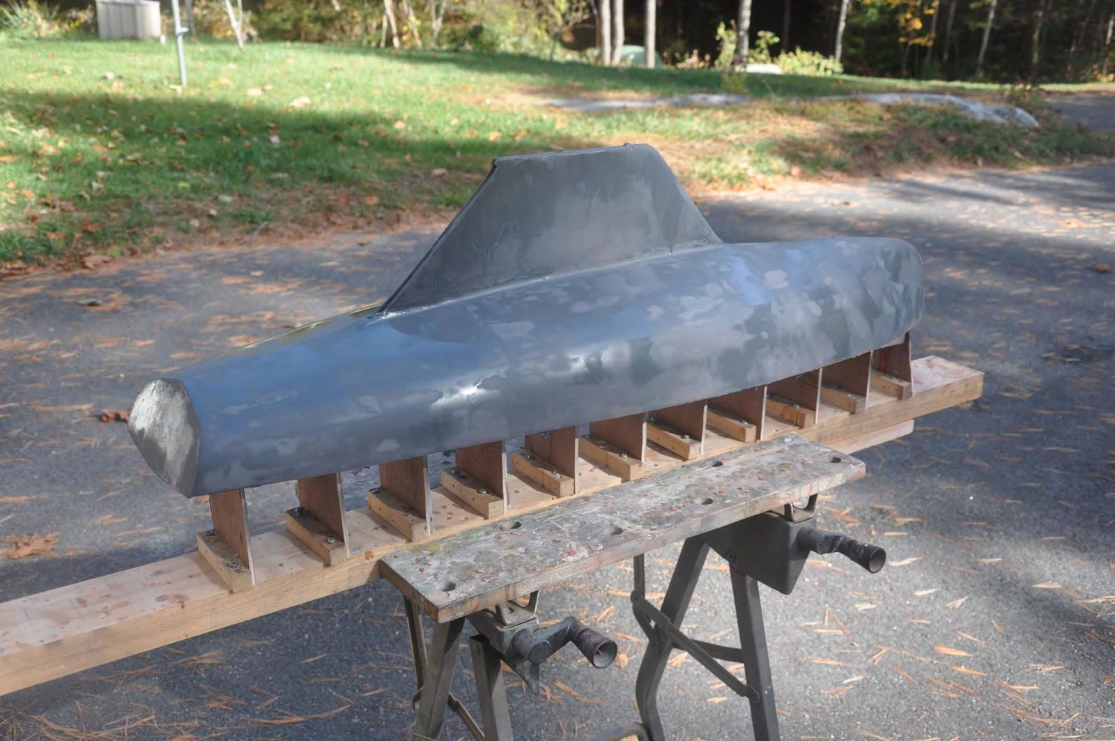
 here is gray finishing primer also form car body store. I like the affect and it is good to see and apply more putty etc. It also gives good sight for adding water lines.
 -
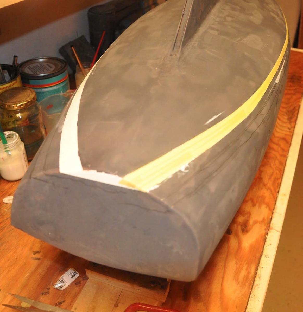
 Here I set up the building board and template to lay out the waterline and boot top. I must admit it took two full tries to get it right.
-
 Being a genious I put 1/4 masking tape over the water base enamel boot top because I like to spray the first construction coat on the bottom.
-
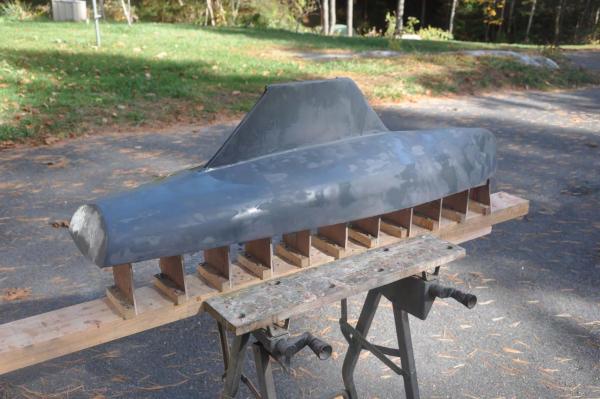
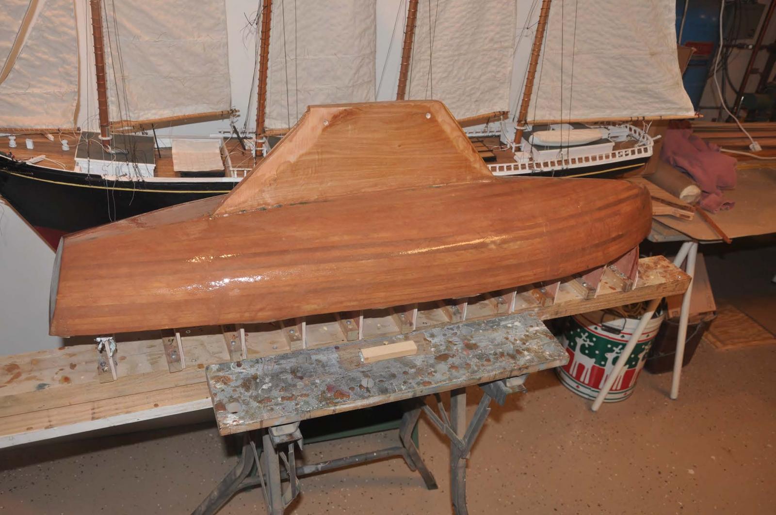
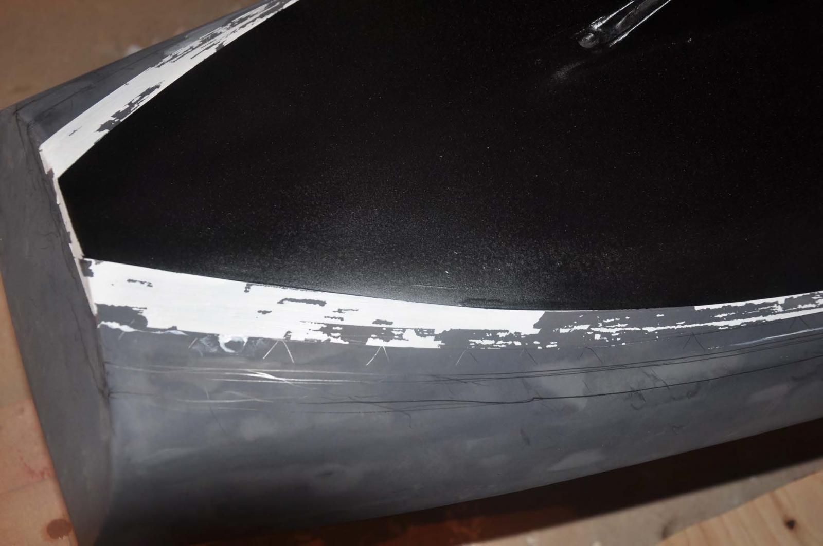
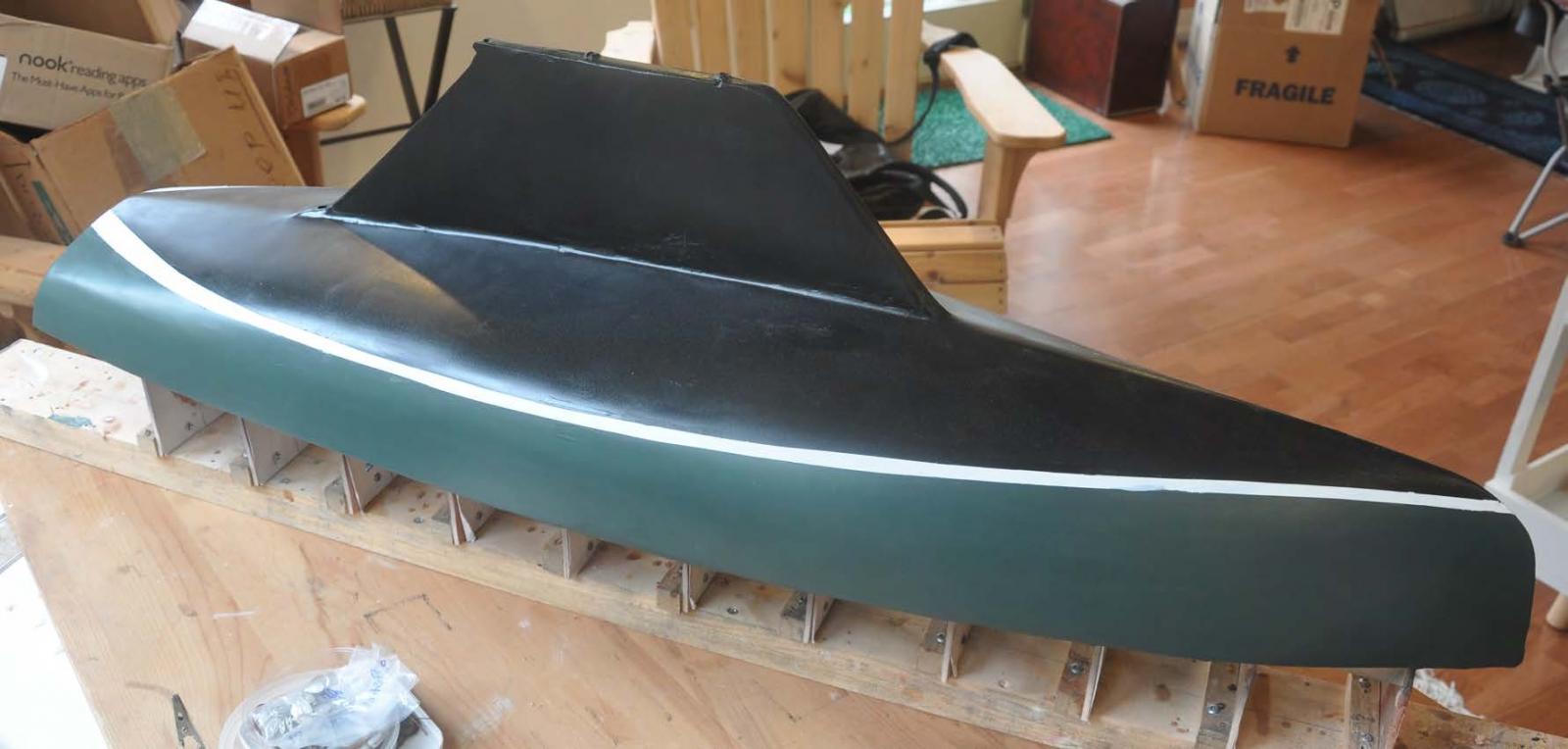
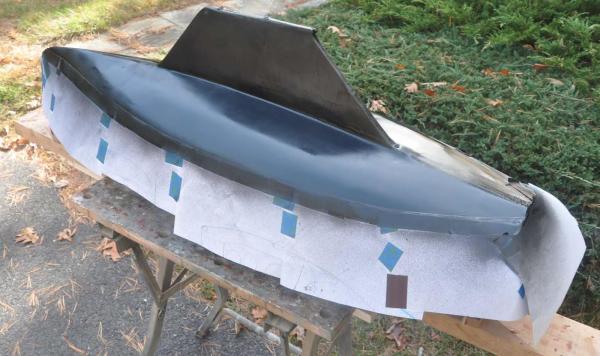 Here we are with our bottom paint sprayed on. I did not choose this color scheme. Historically I understand BITTERSWEET was white with light green bottom and no boot top. The previous owner had it done in dark green with boot top and a racing black bottom paint. My rear admiral wanted a green boat....so guess what? I sure hope it is fast but I am not in love with a black bottom.
-
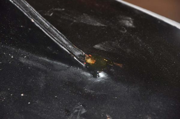
 Here is big oops.....While i was taking off the blue masking tape and paper, some of the boot top masking came with it, and it pulled the water base enamel right with it.
-
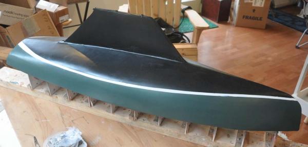 Finally here we are....remember this boat will sail and get bumps. I therefore choose to brush paint my topsides, because it will be repaired many times with a brush.
So we are off to Arizona to see the kids and when i get home...off comes the mold and we turn her over.
cheers
- Omega1234, yvesvidal, avsjerome2003 and 6 others
-
9
-
-
Hi All. During the final surface preparations and completion of the hull, it is important to start figuring out how to make or procure all the items needed either to replicate the boat or to make it sail. If you follow the number sequence of the photos, one can see I bounce back and forth from hull production to fiddling with the fittings. I think that is normal, but it would make it harder to follow this log. Therefore I am making two postings. As stated I am doing these to help demystify the process to encourage more entry level participation. That way maybe we can build a fleet.
My full size boat named BITTERSWEET is the template for hull one of this two hull build. So as we are heading into winter, plans are being finalized for the completion of restoration to the real thing. To help figure out the modeling we shall be using BITTERSWEET
-
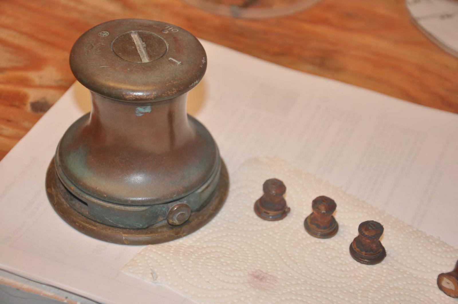
 My first challenge is to make three winches in the classic bronze material to the older 1940ish design. Here is the starboard jib / spinnaker winch on BITTERSWEET. Oh the stainless jib track and unmatched jib block are also going away. all tracks and fitting will be aged bronze. This requirement means finding different way to achieve that.
-
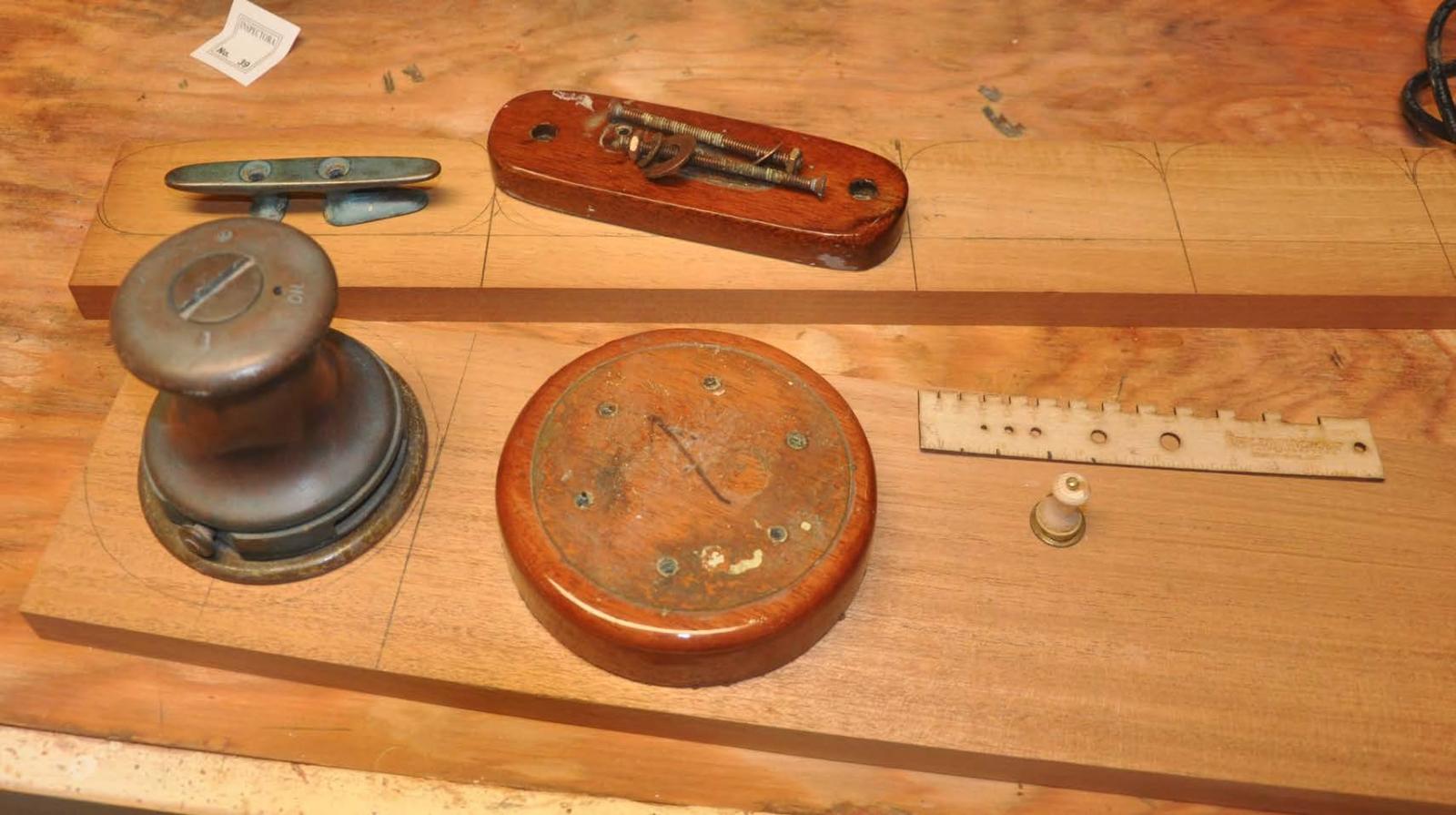
 As part of our work, we shall add a third winch to the foredeck to better facilitate crew handling the jib sheets from that position. To do that we need to procure three fittings, one winch and two jam cleats as well as to make Mahogany bases. Here you can see I have procured Honduras Mahogany and am making the real size plates.
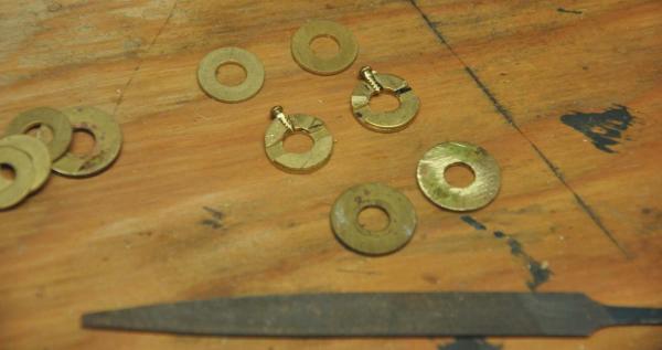
Now to make the scale winch I chose to mock one up. Look in the photo and you can see my first attempt.
 Here I turned a 1/2" dowel to the shape of the winch barrel and used brass washers to build up the base and body. While at the NRG session in Mystic last week, I discussed options with many folks.
- make a mock up that someone could use to make a mold and then use resin
- make a mock up that someone could use to make a mold and then a second mold to use Britannia medal...$$$$
- work on my CAD skills to progress into 3D. then down load a model and sent it off to a printer. again in resin..ok but in nice bronze..$$$$$
- get someone to turn the barrel in brass and continue to assemble as the mock up.......this is my first choice. Oh an I also want to improve cad to be able to do 3D
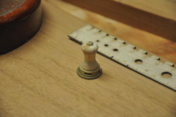
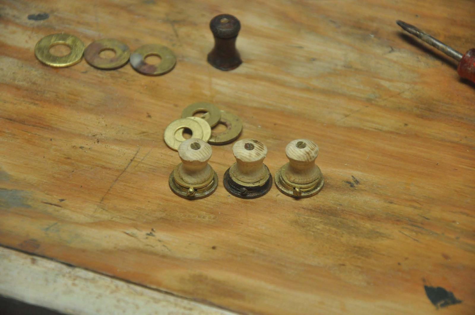
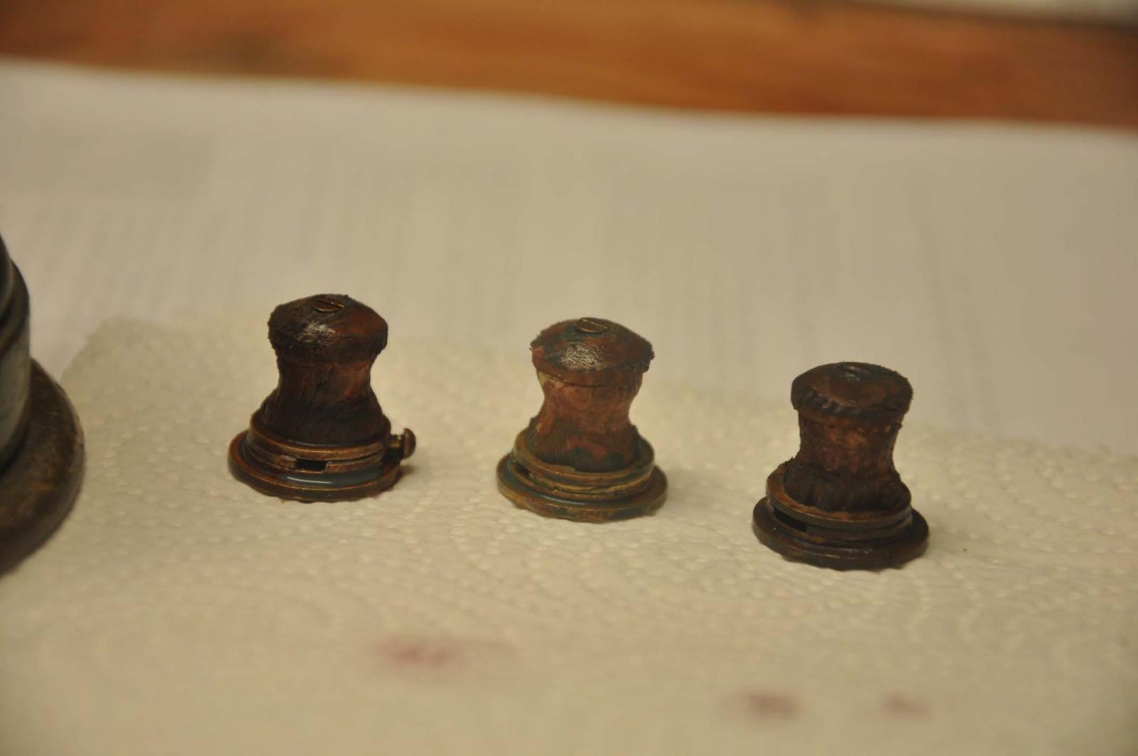
 In the mean time I chose to make up three as place holders. Hopefully they won't have to go to sea.
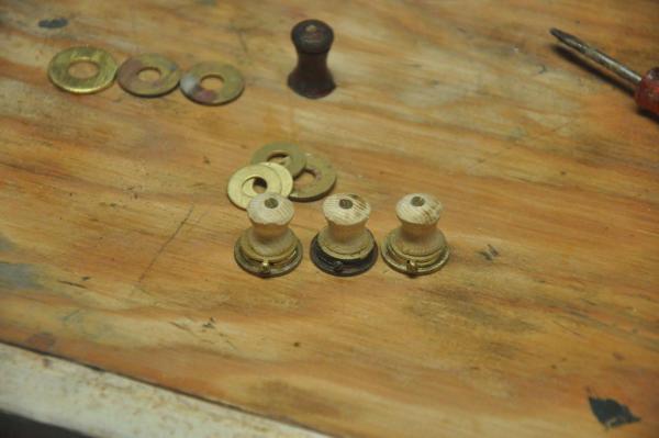 here they are raw and ready to finish.
  finally here they are with a quick attempted finish. per recommendation of Nic from Blue jacket , they are painted the red brown [ called leather brown on the can] and then covered with a green wash. i see here they need more wash, but again " place holder"
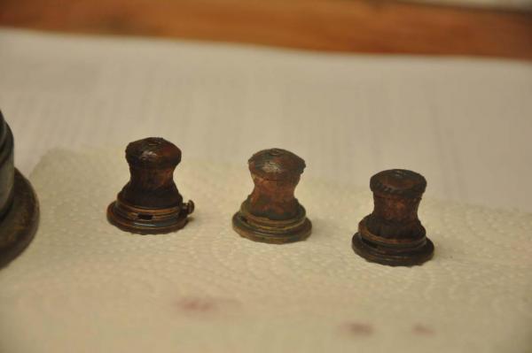 I am sure we are coming back to these. Good news is other boats may not have the same type of winch as racers like the more modern efficiency of sleek black and chrome Harken fittings.
cheers
- NJQUACK, avsjerome2003, G.L. and 9 others
-
12
-
-
Giorgio
Really looks good. In recent reading about schooners in this period, the new boats might have gone out brand new with both decks and deck houses oiled. Soon after the the deck houses were usually painted out . then the smaller elements were often white. Sometimes the waterways and house roofs were dark. Some plans even painted the working area of the decks. My point is from my brief research, I concluded you can chose what you like and be right.
I look forward to you updates. I love the old schooners and yours shall be fun to watch
Cheers
Jon
-
To all those who some day would want to build your own model BHOD , I hope you find the planking step as much fun as I do.
We have had a busy week here in the harbor as work day came at the club and the final club boats were tarped up for winter as more friends left for warmer climates. I even put our little pond dock to sleep for winter today as well. The chase boat is on its sleepers almost ready for a winter nap. Despite all of this. I want to get come progress on this build before a few trips take up our time. The good news is we have spectacular color in the foliage again. Funny though that means we are into fall clean up too.
Building this hull I remind all this is a proto type. I am trying to build it in a way that others can follow. That means others who are not experienced museum quality builders as so many are in this forum. The materiel is accessible and reasonable to work with. That being said there are definitely a few tricky areas. I learned some good lessons going through this step. These lessons will be a challenge to hopefully solved and avoided in the second hull to be started next month.
here we go
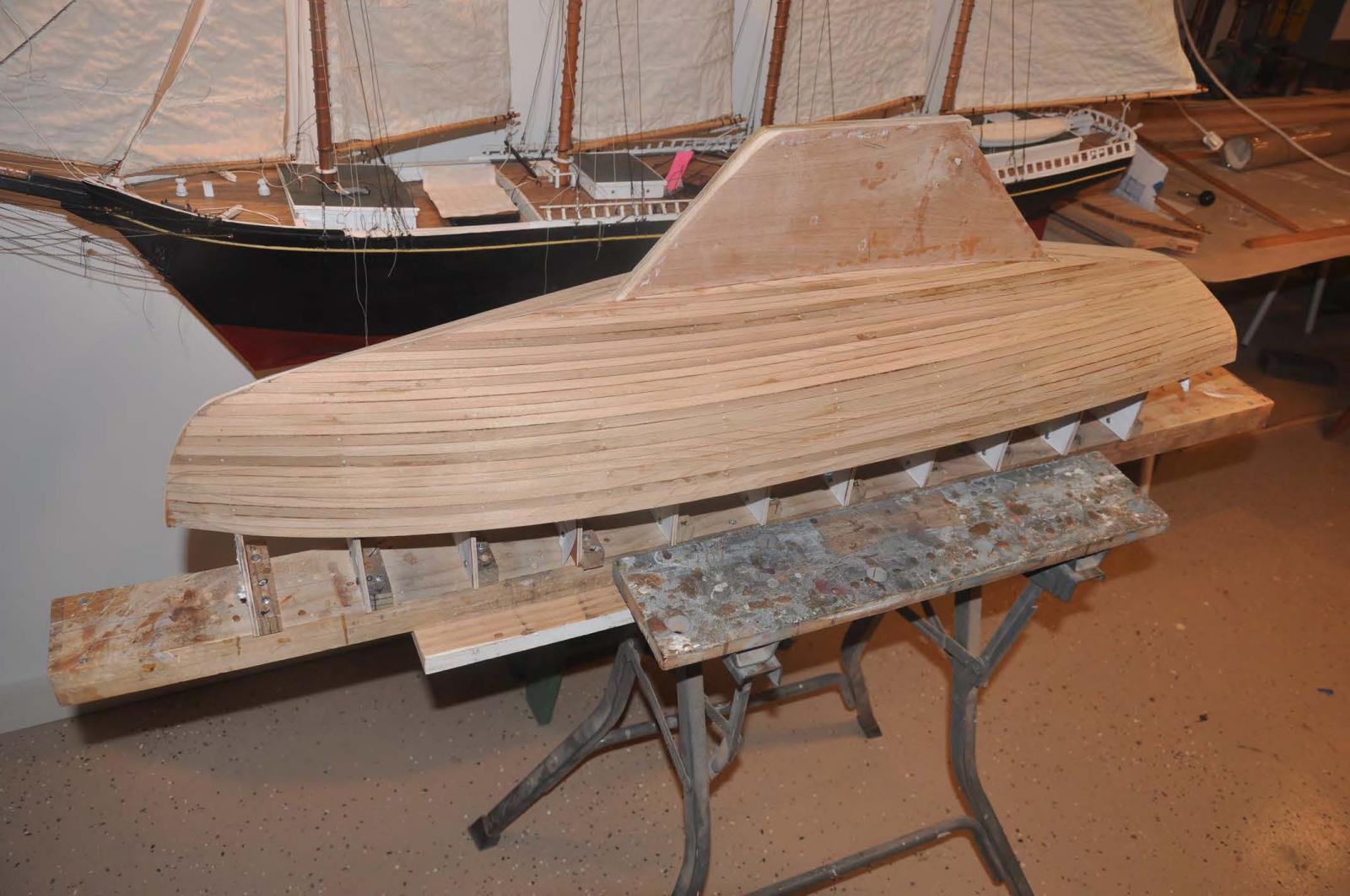
step 2 Planking
Picking up where we left off, the first need was to carve up a transom with blocking and get the bow blocking properly aligned. to do this one needs to extend the shear plank and test the alignment and sand and get it right.
-
 here I had sanded and re-sanded the blocking as I fit the planking to the forms about four times, but I think we are there..... See the nice fit of the planks at the tip of bow...ha ha stand by for the lesson learned.
-
 the transom went pretty quick. I like soft pine for the blocking like the bow. It is easy to sand, glue and drill into for screws and toothpick pegs. For this prototype I plan to have a painted transom. If one chooses to have mahogany, this would be the same but it must be about 1/8 inch further forward to stay inside the boat length. [ the mahonagy would go on after planking. I would use 1/8 planks glued together., similar to those planned for cockpit combing later. the edge would be exposed and real ones are also laminated. I will try it on hull 2.
I said I would move along and only record things that are different or unique to this build. That requirement did not take long.
-
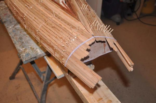
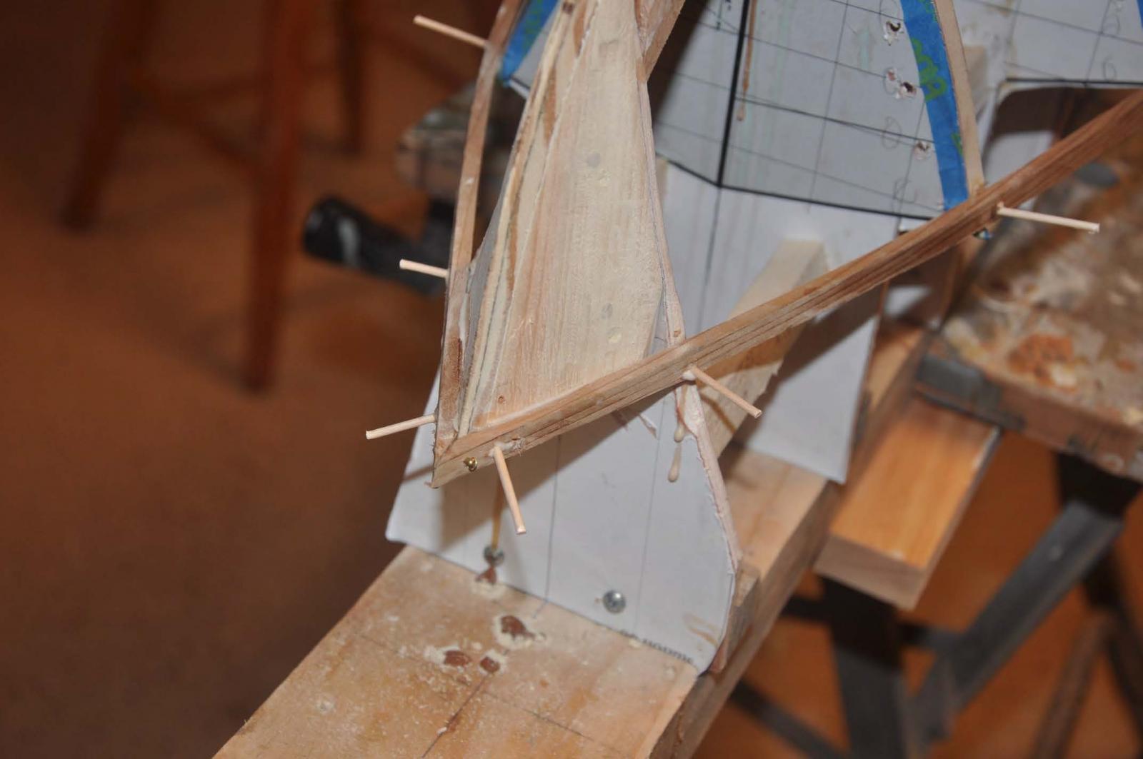
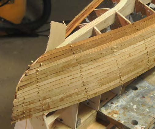
 There is quite twist in the planking. The planks will be visible on the inside of the cockpit, so I chose to run planks all the way through as long as they ran off the transom and needed only one cut end. Due to the multiple twists as well as side bending, I ended up having to use temporary screws to hold the wet planks to dry to shape.....that is another reason for solid blocking at the bow and transom. I did cut the planks when I got below the floor line.
-
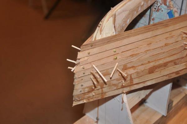 we have a concave..."reverse curve" at the bow. Very quickly I found a need to use several screws on each plank. The planks are tight on the inside due to the curve and loose on the outside.... that is fine. The outside will be filled before fiber glass. Using the 5/16" width gives a good enough curve I found on previous hulls and so far so good here. Again this makes this an easier process to build. Checking the plans the planks are about 5 inches by 1/2" cedar. that would mean 3/4 wide and just over 1/8 thick. I am not sure what material could bend at that scale. i wanted to use cedar, so I do not apologize for just under half size planks.
-
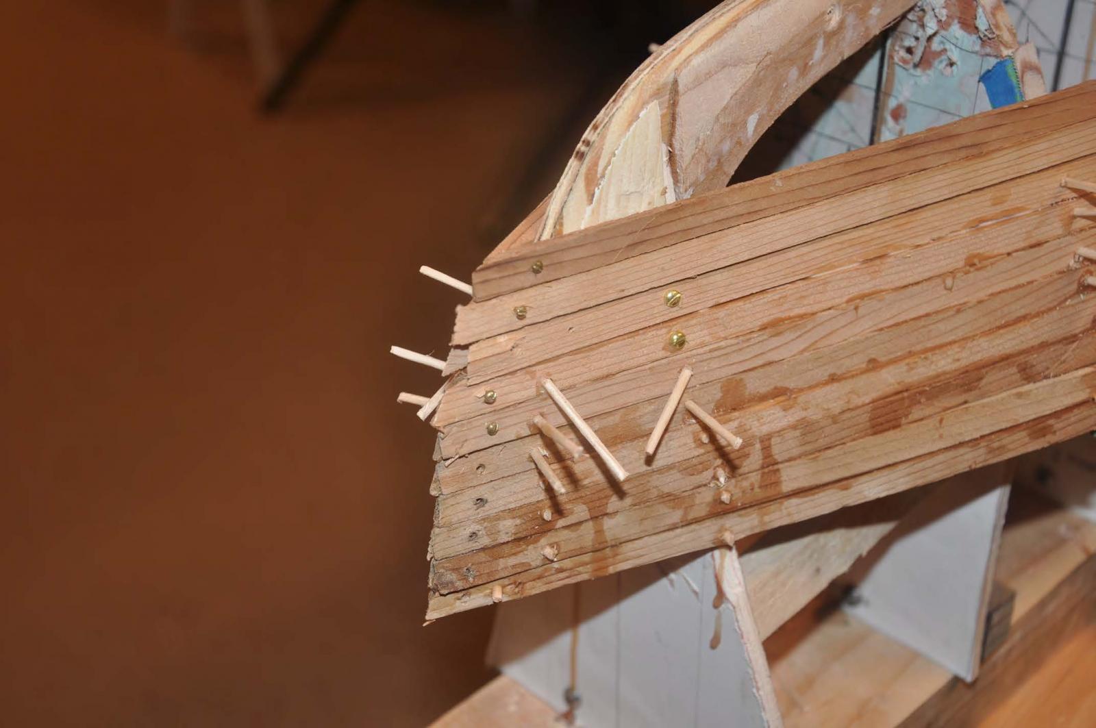
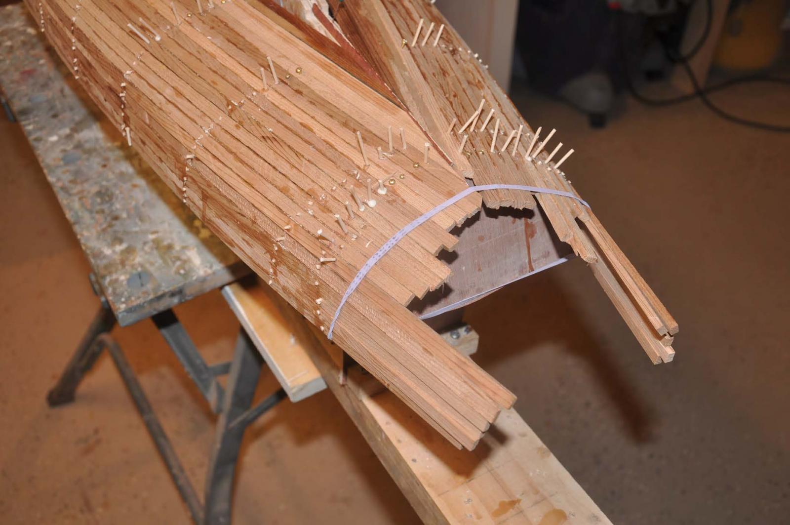
 ....OK here is our first lesson learned
  and possible oops. The reverse curve pulled apart the three planks at the stem as I screwed in tight at station 0..
 -
 The fix was to file and insert a 1/16 plywood cut to form of the stem. I then ran the piece all the way to the keel, so each plank would end on this piece. This trim piece should give a crisp line after sanding. the oops was not knowing its need and not having it all the way around the bow before planking.. hull 2 shall have it!. I had assumed i could achieve that by sanding......we'll see.
-
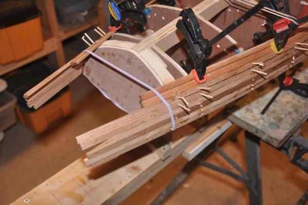
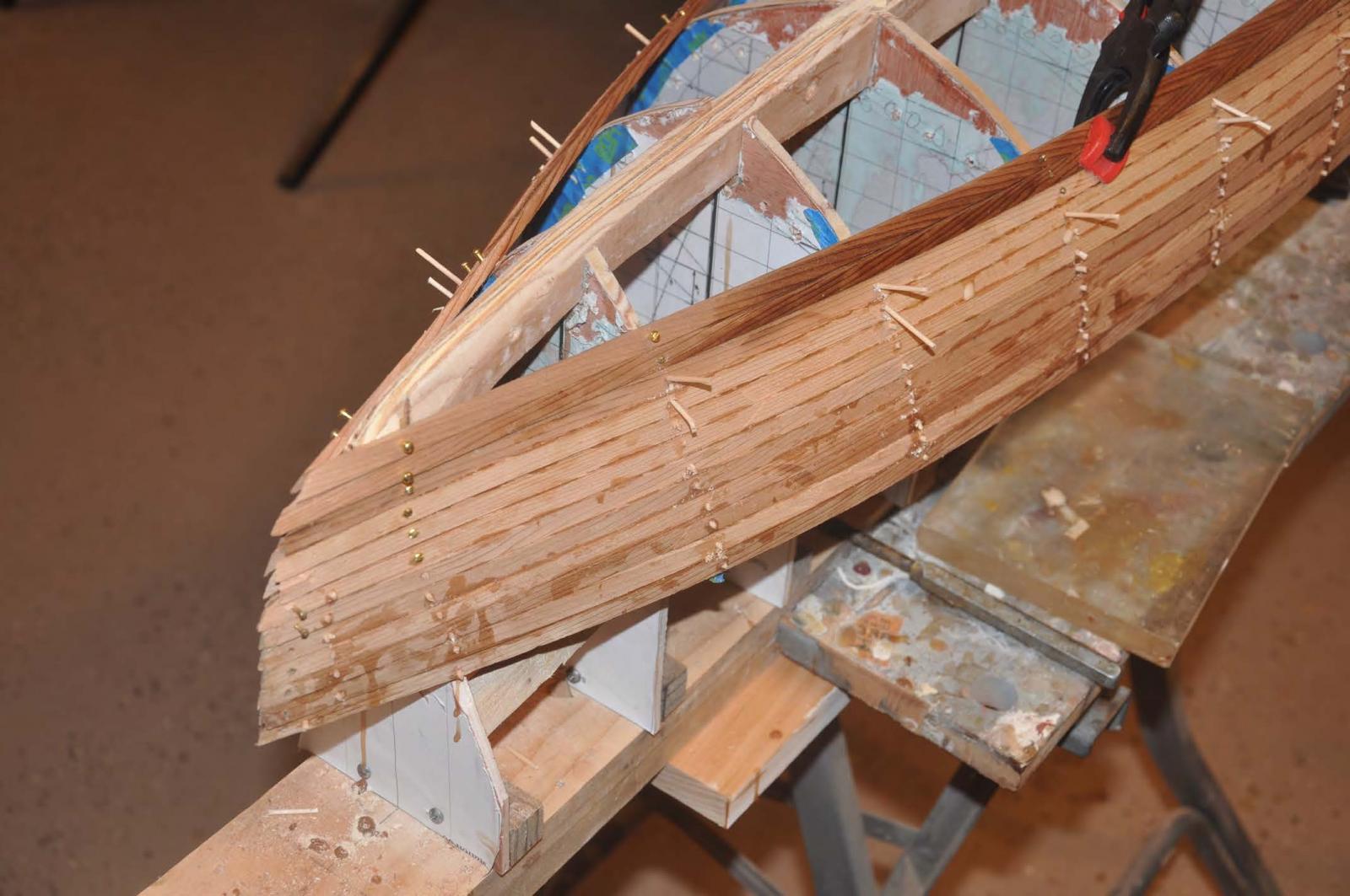
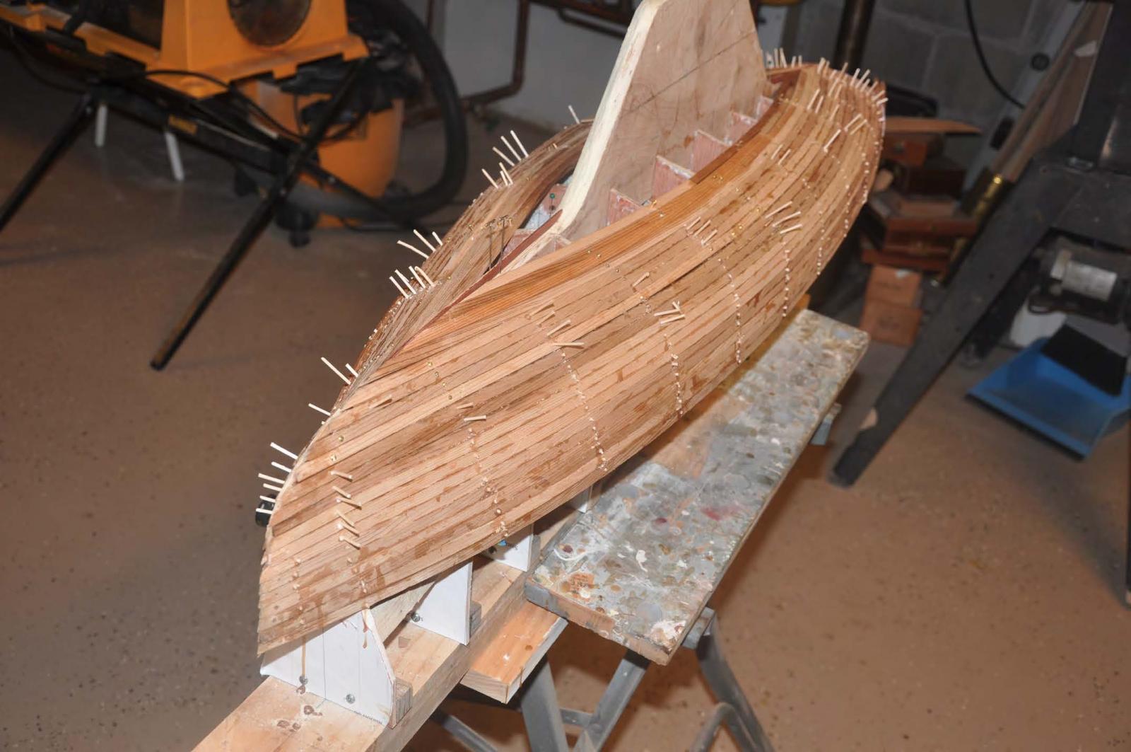
 here we are progressing. 3 or four planks are glued and drying while the next 3-4 are being installed, secured and hopefully drying to shape.
-
 here I have installed a filler piece as well. I always planned this one as the dimension across the keel is perfect at two planks plus 1/16 inch center trim piece.
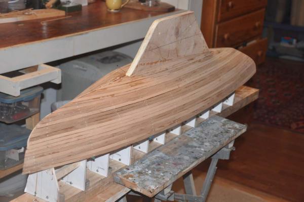 well here we are all planked and one rough sanding done. There are a few items loose and then we need to figure out how to dress up the bow. where the trim piece was added it seams simple. controled sanding and filing is my approach. what ever we do gets covered with cloth and glass then filed sanded filled etc. we'll fix it.
 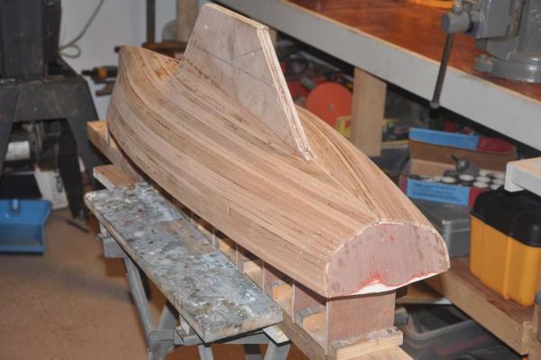 here we have cut and sanded planks back to the transom. If we were going to use mahogany I would use 1/8" solid boards. they would be added to this structure as one wants to cover the ends of the planks. One would need to shorten the placement of the transom that 1/8" *** part of the planning.
OK cheers
-
-
Michael
Thanks for your comments.
I am enjoying working on both a real 1941 boat and making a sailable model at the same time.
One challenge will be to keep it simple, so I can encourage others to build one. For me simple is OK but I want it to be accurate too. I will be struggling to make bronze fittings.
Cheers
- mtaylor, michael mott and Omega1234
-
3
-
Mike
I just enjoyed a good hour reading your log. I am trying to to learn as I go and there are so many great ideas within your work. First is the integrated lead keel. Then the beautiful metal work. Wow
Thanks for sharing.
Jon
- mikegerber, Dimitris71 and Omega1234
-
3


Boothbay Harbor One Design 1938 by Jond - FINISHED - 1:6 - RADIO - 21' racing sloop
in - Build logs for subjects built 1901 - Present Day
Posted
Well a big day arrived, a small milestone. Bittersweet junior has left the shop and made it to the sail loft. here are a few updates of how it went.
the final task in the shop was to install the teak sole.
So let's get the standing rigging up and the sails bent. First of all let's discuss the process of the sail design for this model. First of all we have the original design of 1938
my conclusion was to eventually make a sail exactly like this drawing, and the photo early in this log for display only. for sailing i will work with a real RC class and use 2 oz Dacron .made by a pro.
step one was to request panel drawings of the current class design for the boat. Sailing Partners of Vermont now have the rights and host the design of our sails. They kindly sent me images and were supportive of my effort and agreed with me that it is best to reduce the area for a scale model to sail better.
Now came my work and decisions. i took the new panel layouts and embedded them into TurboCAD. I scaled both up to full and then down to model size.
drum roll please
cheers