Jond
-
Posts
877 -
Joined
-
Last visited
Content Type
Profiles
Forums
Gallery
Events
Everything posted by Jond
-
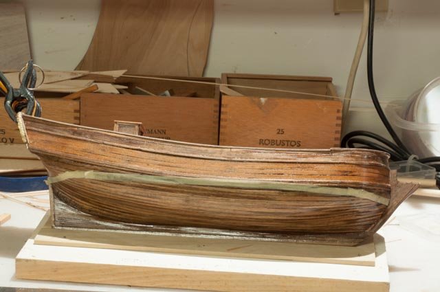
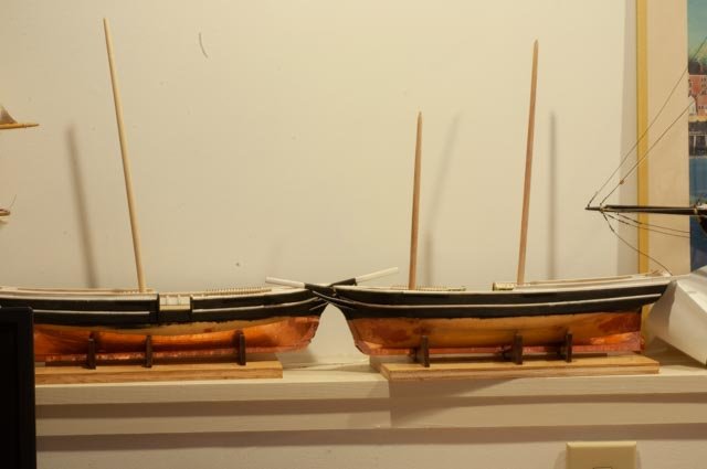
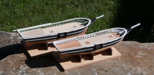
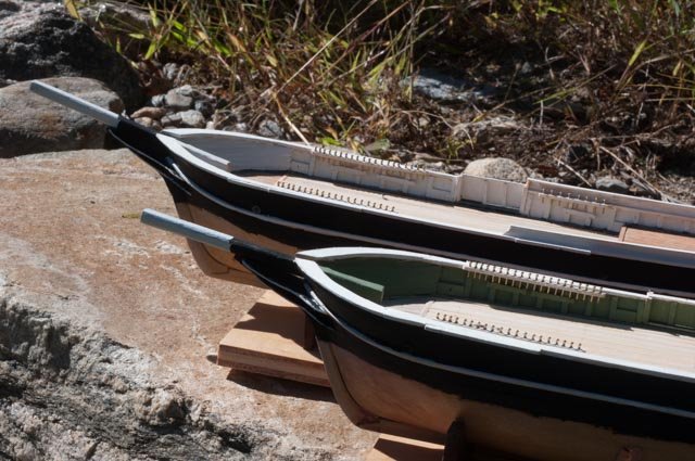
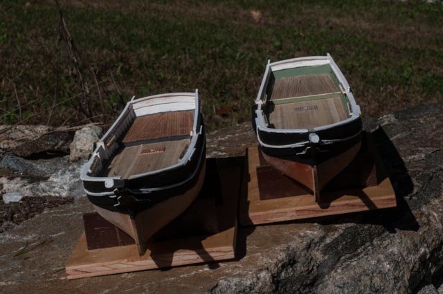
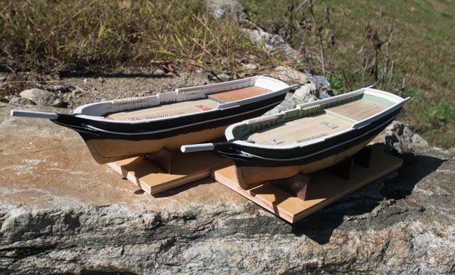
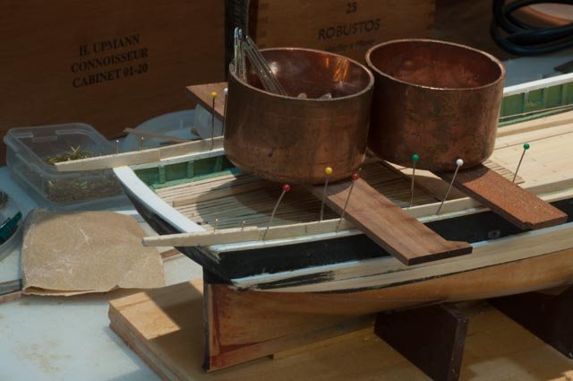
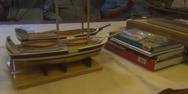
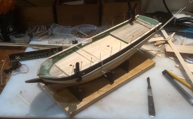
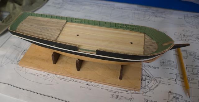
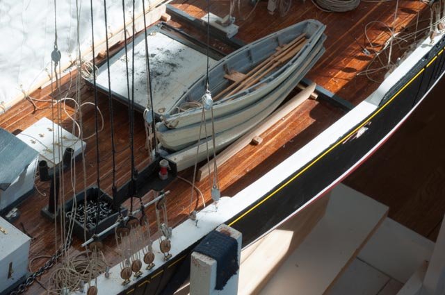
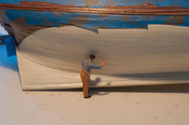
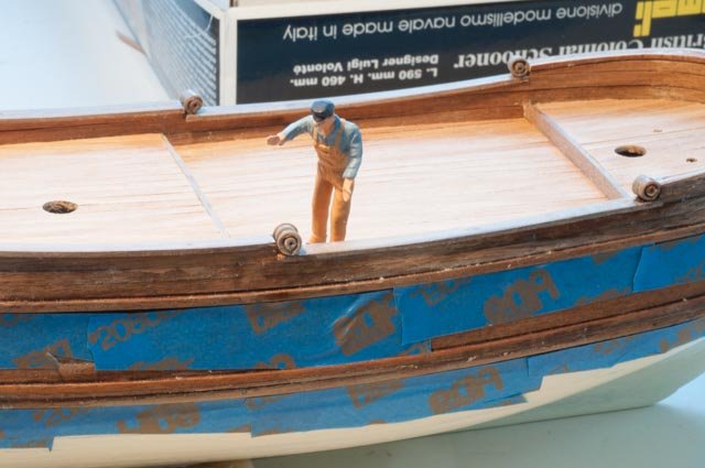
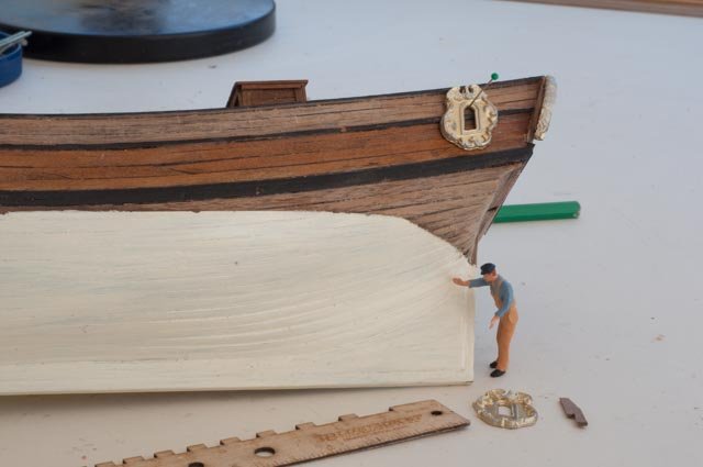
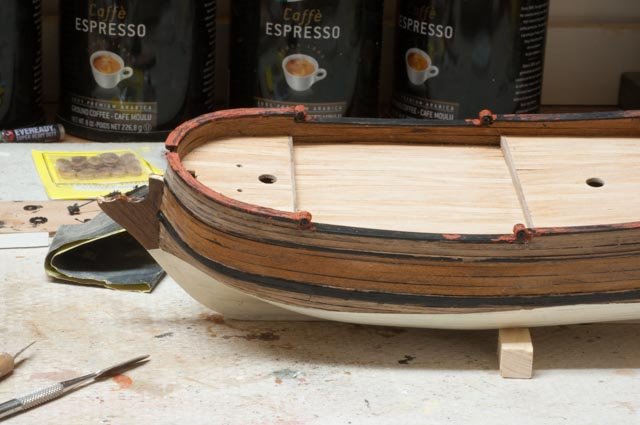
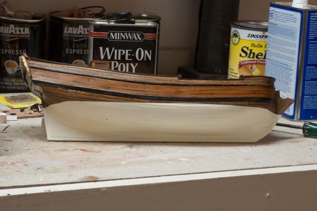
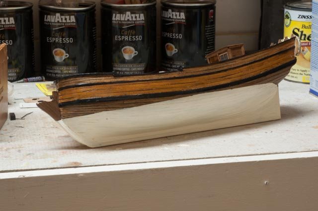
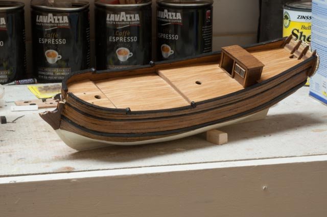
 This post is to record an unplanned but wonderful delay in this build. A local vendor in town has decided to celebrate Boothbay schooners in his new maritime focused store. The focus shall aim at those Schooners built in Boothbay. As stated multiple times in my previous builds, both studying and modeling these locally built boats has been my desire for years. Charles Notman was built as a prototype for building some of the 12 big 4 masted schooners built here [ 20 in the county] near the end of the schooner development in 1921. The Maine Ice industry use of schooners and wintertime labor was also a big part of our local history including a 500-foot-long dock feeding up to 4 schooners at a time in the harbor. The great sardine fleets, locally built packet brigs and barks etc. So what does that mean……. These whalers will be on the shelf for some time. Similar sized packet brigs were built here at the same time as the whalers, so who knows what will happen. I will return to spruce up Charles Notman as I am scheduled to talk about the big schooners next summer, and there are several items to be completed and fixed. I shall rebuild and complete Bowdoin hopefully in my first diorama, build a Pinky in 1:24 scale etc. etc. Anyway my other logs will get updates and I will switch to a new one on Bowdoin as that was a first item to get done, so as we pick up this project… Here we see I partially completed my first attempt at copper tape on a bottom. My approach when I got to this stage was to order another roll. I must say the challenge of using this tape is real. It just does not like to easily stick. I will likely remove it all, sand and smooth up the finish with several more coats of buffed varnish. A lesson to learned it needs to be very smooth to hold. Here we see a supply of mock up barrels I bought. I plan to figure out how to make them, as a dock side or even at sea rendering scene would need many, and in that case they should be home made. Also I want to learn to make some hollow ones on the lathe. So much to do! Finally, here we are resting on the shelf. All loose materials, plans and notes back in the box. Not to be forgotten so Bowdoin is next up All for now...we shall return
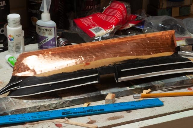

-
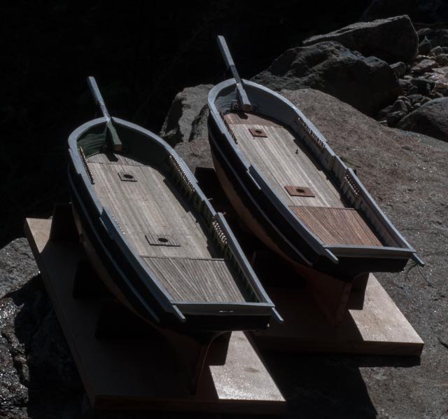
Rich good to see you making progress. The dories look great. I have been hit by a great opportunity to get back into schooners, so my kate cory will be on hold for a few months...… I'll post about it later this week. It's a funny thing however, I immediately have to build three dories for the Bowdoin …...oh well . I believe a guide to measuring an amount of added detail is the comfort of getting ones thumbs stuck trying to get that next little part attached. If they , the thumbs that is, can get in and out, it's fun to keep going. example...I love your cleats. cheers
- 109 replies
-
- 1
-

-
- model shipways
- kate cory
- (and 1 more)
-
i wanted to get to a stopping point as diversions have come up including a trip west. I am reasonably happy with the rough paint job. It is not the last however. I assume working the bottom and getting the bow sprit done will get me to a point to focus on redoing and finishing that process. I got advice on using foam sanding sponges after the first painting on small surfaces like the whale boats. This small scale is giving me hair like fibers of the wood, dust and roughness and I need to learn to deal with it. Using a scalpel for cutting has helped a lot. Good by x-acto knives. I have also read in a recent blog that working with bass wood at this scale it is necessary to get one coat on and then final sanding. I look forward to trying it. The small whalers all need that on there outer planking. I went outside and took four pictures with normal lens and four with wide angle to suck in more color and add perspective. These photos show me so many defects that I know I have a way to go, but also the wonderful early fall season. As photography is part of learning how to do these logs, I find it interesting as I go back and forth with a 60 MM macro that on FD nikon that is really 90 MM and a 24 MM I keep on the FX body, so it stays at 24 MM... I really see differences. My photos have a long way to go though, and it's fun to try things out. here are 4 with normal lens.. at 90 MM the images seem flat. I set the aperture on max to improve the field but outside i would be better to reduce it and loose the background. and here 4 views with the 24 MM shot on auto. the exaggerated perspective and deep field in focus is interesting. anyway I am off to cowboy-land for a bit. I just tried the copper bottom tape and wow I have a lot to learn when I get back cheers
-
Mike I am slow right now as our actual sailing season ends, boat just out of the water, and we will take a trip west for a few weeks. When back I plan to move along and the boats will become different. I want one boat to be working at sea. I found a site that sells plans for keel and bulkhead lines of whales. I think if I make the mold and fill it with sculpy I might make a whale. I have a sheet of lexan and may cut it out at waterline for Kc and a whale by her side and a small boat in the water. If bad I can just trash it. I have many visuals in books showing the process. I believe in the brig they may have rigged a storm staysail in place of the furled Main. I say that because the fishing schooners did that. There maybe a main staysail and a jib set.. Not sure but lots of fun studying Boat two......pavilion has fore sail like a schooner. I will likely have it sailing with bulkhead closed, or do a dockside showing unloading of barrels. lots to think about . This will be first attempt of diorama l keep looking for build logs on making thin waterline so you above and below water. There are some incredible examples in lunenberg museum …..I consider the opportunity here low risk practice and learning before I try charles morgan next year. Cheers
-
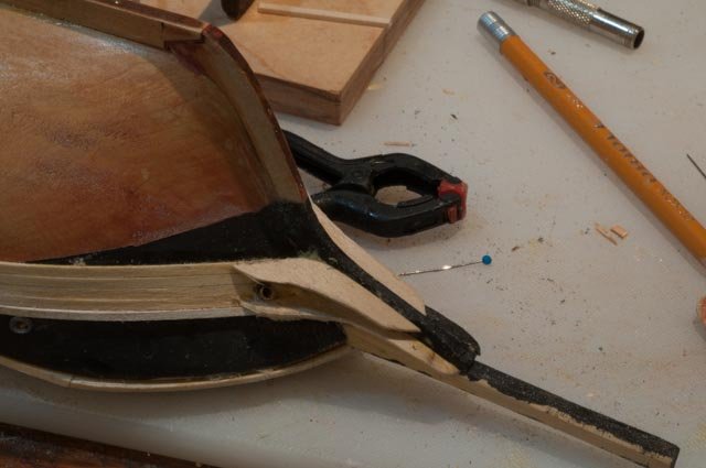
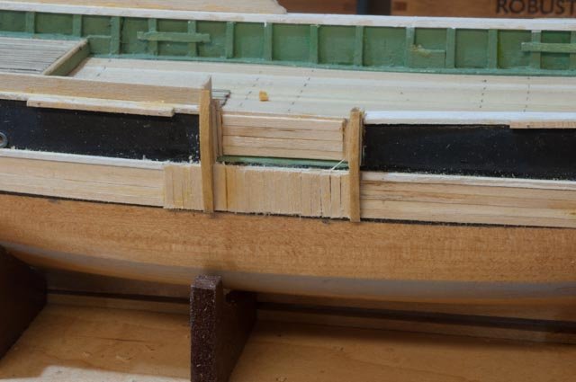
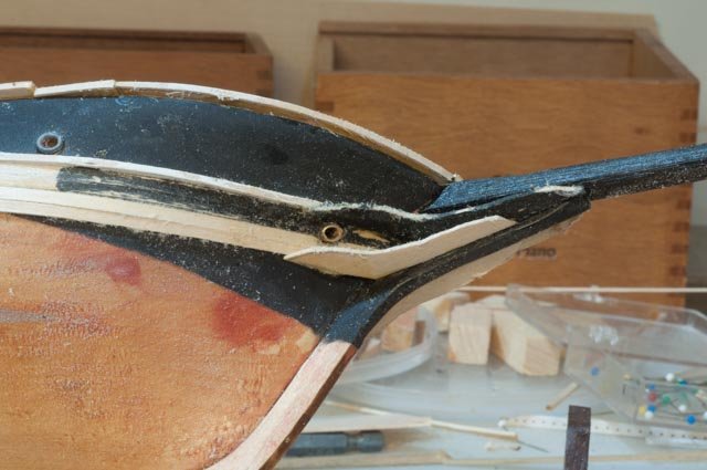
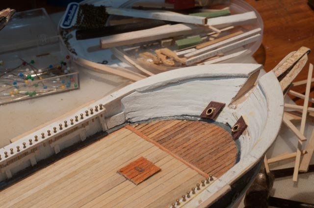
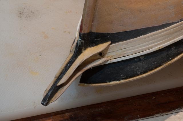
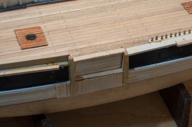
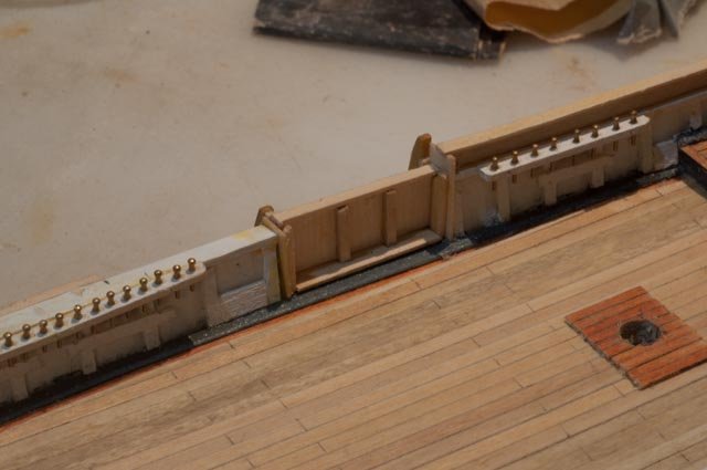
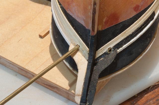
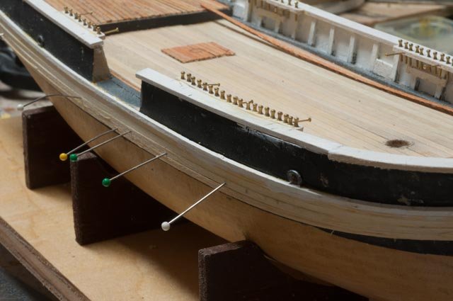
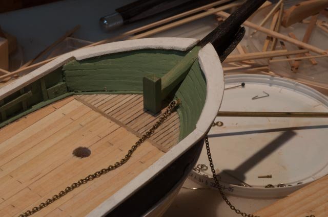
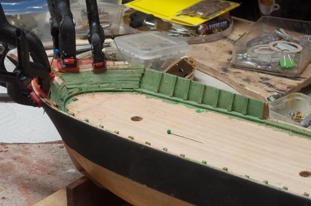
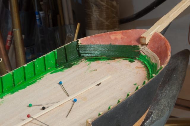
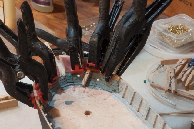
I have some more work to get done before starting the copper bottom …I think. I am not sure what is right. The top gallant rail is not too strong and they include all of this in the books as the first phase. They are not too clear about when and how to do the bottom. · My favorite adventure so far is getting these cheek knees installed. We are slowly getting there…maybe. each time I look I want to make them smaller. · The top gallant rail and “rooster tails”. I already knocked them off once, so maybe this is out of sequence. I decided so far not to so the knight heads and buffalo rail until after the bottom is on, as I like removing the bowsprit. I made a little cut out piece that goes in after the knight heads that I will cut through the cap rail for strength. · The cutaway bulkhead is the first fun piece. · Second boat cheeks · Top gallant on stern · Hawser pipe surrounds · Sanding of wales and cheeks ready for trial painting · Bulkhead installed for sailing · Bulkhead from inside boat two. One of these brigs will have it open and stored….not sure where but that’s a plan at least. it would clearly block access to the pin rails if just to one side. I am going to do a first paint out to see what we have. I expect damage during copper so I will save touch of then. All for know
-
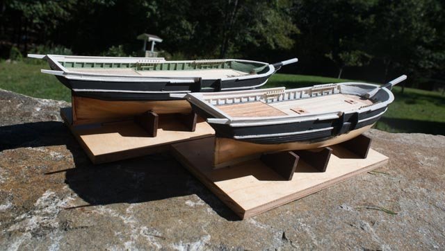
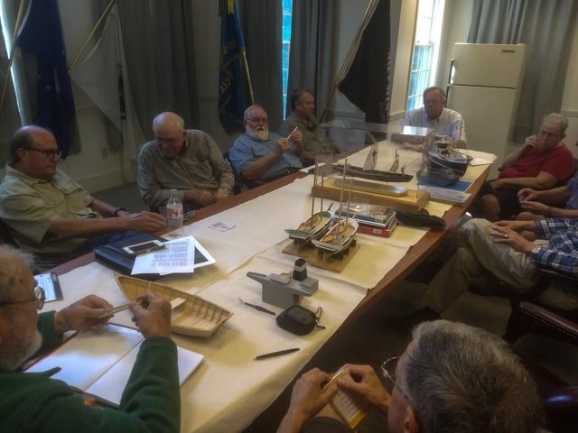
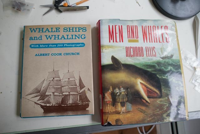
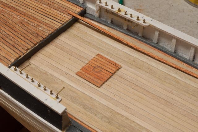
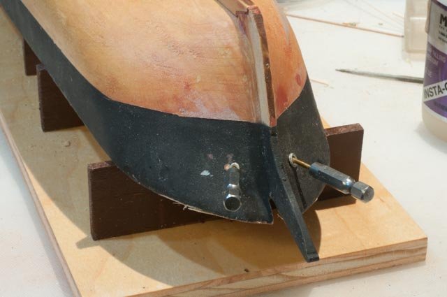
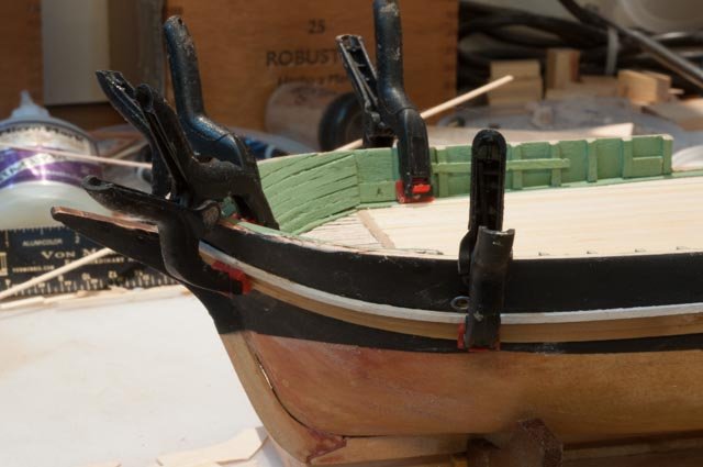
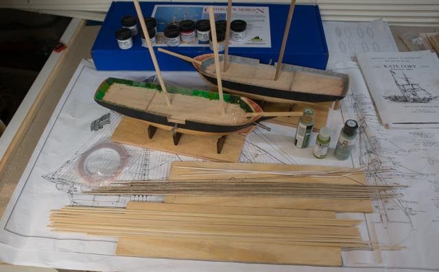
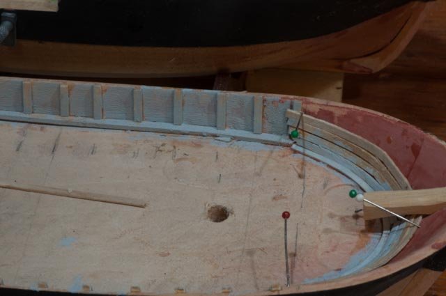
Off to the Downeast Shipmodelers Guild Both models cleaned up ok but are still very rough and have a whaler on board in first the planned color schemes. · Here we are after lunch sitting around the table · I shared three of the 12 books I have for this build and a few tales of the amazing travels of little 75-80 foot brigs. · …Whales Ships and Whaling by Church is listed in several build logs as a great collection of visuals for anyone taking this venture. Men and Whales by Ellis is simply amazing. I plan on it being s great winter read. it is encyclopedic in its approach and scope. I also took the Pavilion book I mentioned in an earlier post. I will list all the books in my research as we go along. After we got over the banter about how I was going to sail such small models [ my recent previous builds all were sailable] we got into painting skills for these static models and how to display in water. I learned to keep working in artist acrylic paint but when ready, and before rigging, spray on clear coat to fill in and get a much smoother finish. We talked about water display, but I’ll hold that for future discussion. Back in the shop I needed to finish the basic work to get above becks done to be beyond any rough handling. Then I can begin my first attempt at a copper bottom. · First up is to get hawser pipes done. I went around a bit trying to select a chain size for this new scale to me of 1:64. A settled on 15 per inch but want to know more. This is not a three masted bark, but a under 80-foot brig. That choice gave me the pipe size. I have also started my third attempt to build the cheek knees. They may be ugly, but we’ll get there I hope. · I decided to put on the wales. I had hesitated because I am not sure how it works with ending the copper about 1/16th inch below. I feel comfortable pinning to the solid hull, as I can fill the pin holes before painting. · I am guessing that the pads around the masts were the same oiled material as the normal deck and not the light pine sheathing. · I temporarily strung some chain to check it out. Also, I notice others have modeled with chains on both sides. Considering the primitive windless I can not image sending out hundreds of feet of chain. The choice of rope however would have lightened the load involved with hand cranking. Anyway, I will continue with what is shown on plans and study to see if lines were used for deeper waters. perhaps they simply did not plan to anchor in anything very deep. All for now Cheers
-
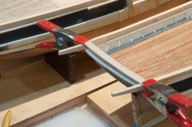
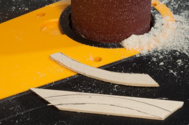
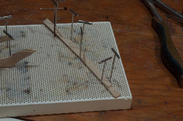
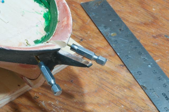
It is time to get ready for the first sharing of this project with our local Modeling group. The Downeast Shipmodeler’s Guild meets monthly at or near the Maine Maritime Museum. We have some good builders in a very diverse spectrum, and I always learn something new. · I have added ceilings and seats in some of the whalers and needed to get paint in them before it was too late. I was experimenting with yellow and tan and light gray at this point · So a few days before the meeting I put my things together getting ready for the meeting I decided that I needed to get more done so I could better discuss the color issues on the main hulls and I think I should get more paint on the whalers so let’s go · Here is second attempt on the cheek knees. Following the book, I am working on building them 1/16 thick through lamination. I had to put this on hold since not enough time. · I wanted to put on the cap rails and get a white coat on them. For the transom I laminated two sheets to get the arch. · Here the second sheet fills in · For the bow I made split pieces and just love this new tool. Switching to a spindle I made four of these pieces in about ten minutes · Here we are one evening with cap rail on….note another oops. Here on KN I ran the starboard cap rail all the way forward, so it would take the small bend after wetting in ammonia water solution. On Pav I wanted to use a scrap piece, so I cut it at the side opening. It was then impossible for the forward piece · Overnight I had to bend a soaked piece to complete the rail Now we are ready to go see how we are doing. Off to the guild cheers
-
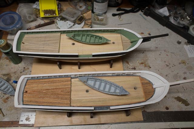
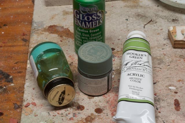
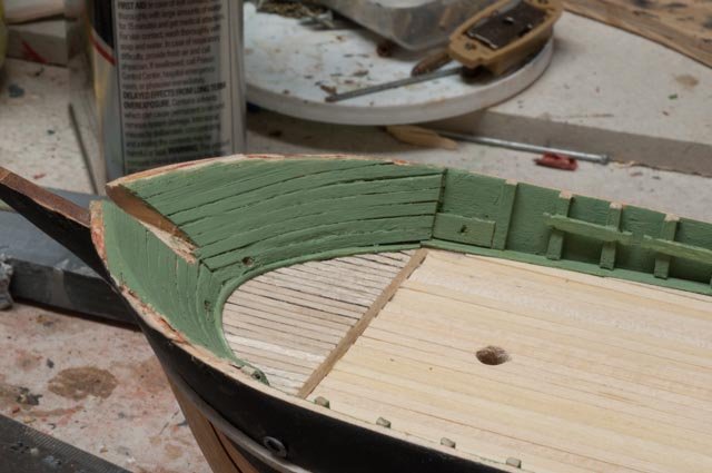
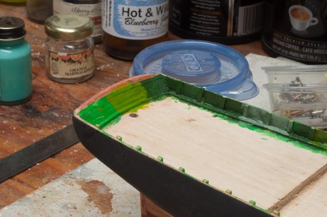
I just made a successful trip to Michaels I hope to get some new paints… · The tube on the right shows a color I liked. It came from the local store and produced the very dark green. I guess you cannot tell paint form the cover. the oily mess is rthe bottle that came in one of theold kits....ugly. the next sea green is too gray and the xmas green just awful. · I painted all the greens I bought at Michaels and settled on this one….some kind of mossy meadow. Also we're getting near the top on the bow planking. several repairs in the near future I see in the photo · Here I am on the outside of Pavilion adding the anchor hawser holes. I need to find them and the wales line up so I can design the cheek knees. · This is my first unsuccessful attempt to build cheek knees for the bow stem. I must say the plans to do not show them and the instructions show nice diagram but no dimensions. It’s time to figure out the decks on Pavilion. · Here I am showing the colored deck from KC. The KC build as of now is to be 'newish'...the brig only lasted a few years. I want Pavilion to be old because she was converted to whaling after 8 years and whaled for nearly 25 years. Let’s experiment and come back to this one. · I believe I am showing 'newish' deck here in the bow area and very new sheathing · Now it’s time to add the exterior wales · Here we have the first deck in place all for now
-
it is a nice way to end the summer.....or should I say it's a nice way to begin the fall. She looks great and I look forward to your copper bottom job. I have never done that and look forward to the lesson. cheers
- 145 replies
-
- 1
-
-
- model shipways
- charles w. morgan
- (and 1 more)
-
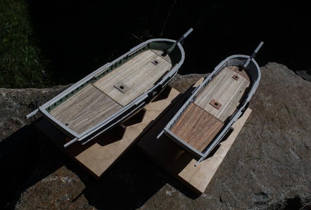
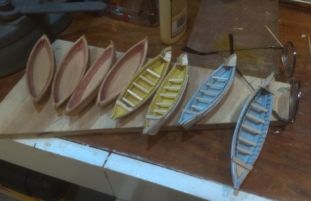
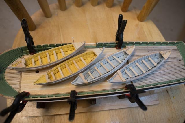
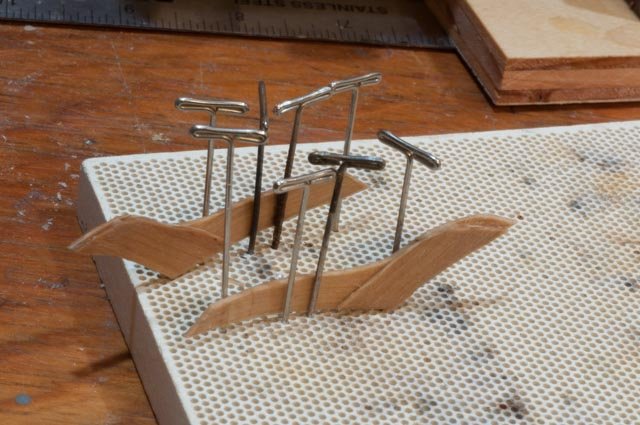
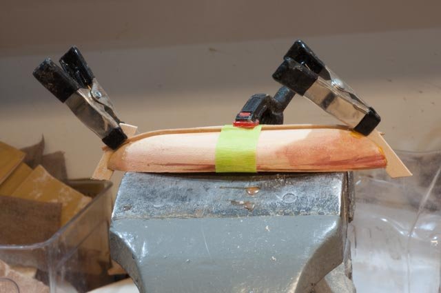
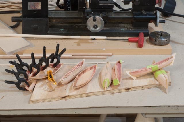
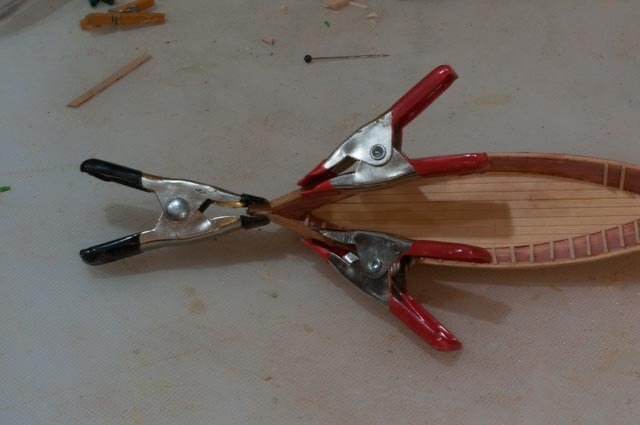
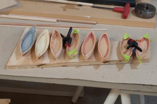
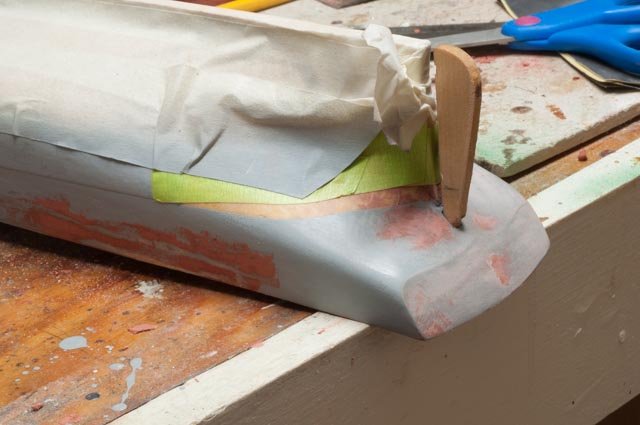
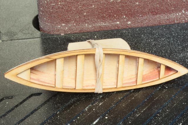
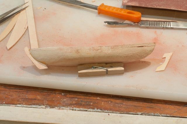
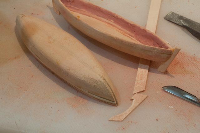
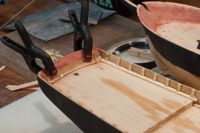
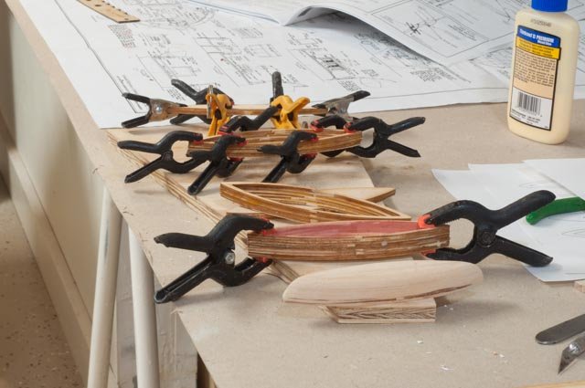
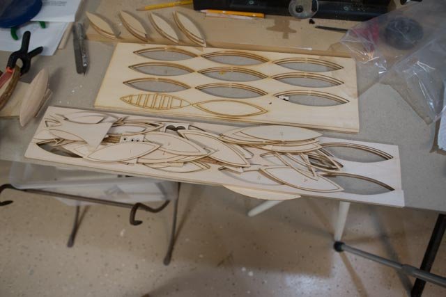
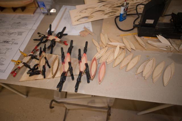
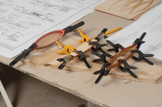
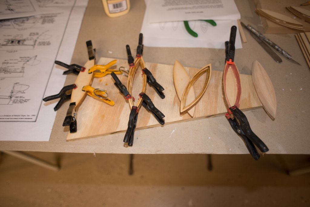
I want to share some more progress on the eight whalers and two main hull topsides. I am starting on the slippery slope of finding the level of detail for the whalers. As this is my first attempt, I am holding back my expectation. I also need to make decision on the coloring for Pavilion. The older photos I see in books, and the more paintings I see also in the whaling books, I find the boats to often be white on the outside. So, this is something easy to change but as I start, they will be white. · The beauty of doing many of these little boats is that by the third one in, I begin to get the hang of it. Here on the early boat I cut the wet keel to the right size and fitted it into the stem and pinched it with the clamp to dry before gluing. By boat three I learned to keep the wet keel about .5-inch-long at each end and bend it down past the stem and tape it to dry. Faster and better fit after drying out. · Here we have the assembly line. ceilings on the left, keels in the center and the last stems and gunnels are on the right · Now we need the bow chocks. Here they are being shaped. Also, the sole and ribs are in and we are awaiting the ceiling planks here we see the first painting experiment on the the whalers Back to our hulls. I have been to the local arts store and found a paint that on the cover looked good……but · The KC will carry on with the green theme and Pavilion will be older and in the black and white theme. Now for the decks.....I have taken the two deck materials and tried to get the color right. I learned the hard way that if decking is veneer or even 1/32 inch, it is better to stain and/or to add one coat of hand rubbed poly before introducing any glue. Even with water rinse I have failed in the past to keep all glue away from the surface and there is not enough wood to deep sand for stain. It is I and not the process on this one…So here is color scheme for KC decking. · It’s time to get the anchor holes roughed in, so we can work around them. Also, one hole was off and easier to patch up and re-drill now than later. · I have cut through for the bow sprit started the inside planking of the bow. · Here on KC we see some bow planking in place and the first local shop artist paint……too dark for me so off to Michael's…a 50-mile trip · Working our way up the inside of the bow gets very tricky for the ceiling planking. Fortunately, with a painted finish, I can use pins and then patch and paint. here i tried gray but have voted it down since I saw white in old photos. · The transom is much easier to do. You can see all the experimental painting on the bulkheads. This will be solved soon. All for now cheers
-
I am enjoying this build as I start my first whalers. I have eight little whalers and having this same kit on my shelf gives an incredible amount of information through the plans. I hope to build this next year. I look forward to seeing you work through the issues Cheers Jon
- 21 replies
-
- 1
-
-
- whaleboat
- model shipways
- (and 1 more)
-
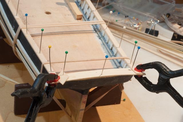
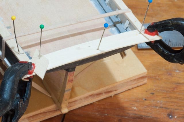
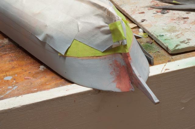
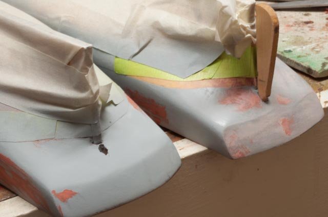
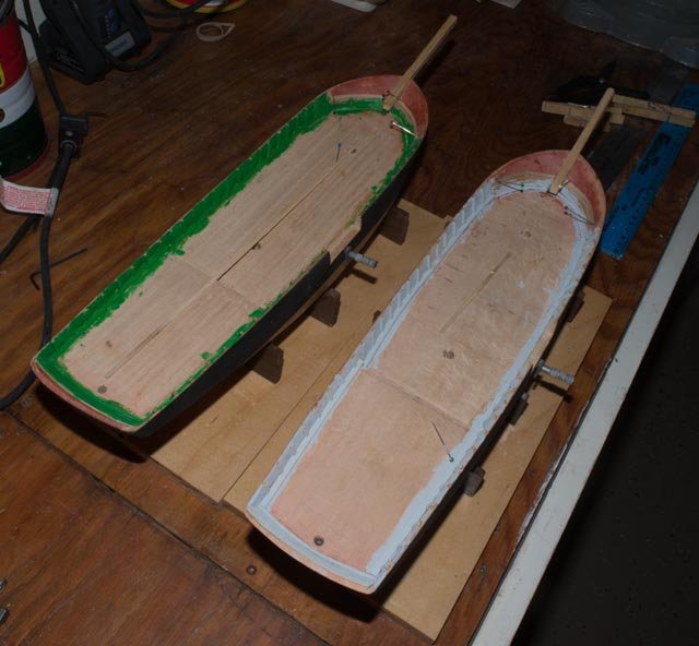
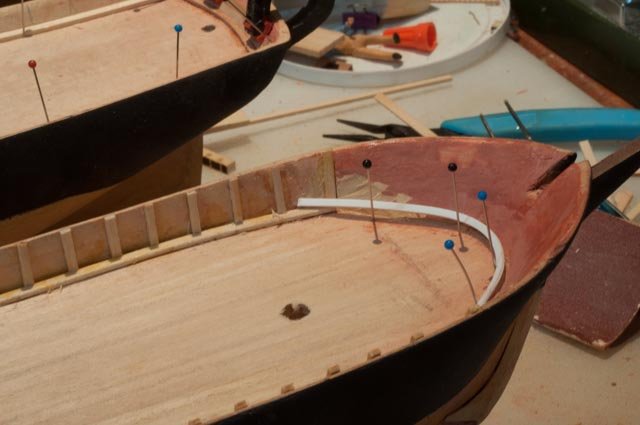
Now the first big oops…. · back in the shop looking at the results it does not take long to see the affects of the swinging line. The water line crept up. I have sanded and re-masked for painting · Proving it was the string we find the same problem at the other end · And yes, both ships needed the rework…. back to the garage Now it is time to start finding the color scheme of the decks of the two brigs. I have now read the book on pavilion. Great story and amazing travel log. She made it to the pacific and ultimate found her demise in the North Arctic sea. This was pre GPS and only a 79 foot ship….wow Just before this primer, I started to add the interior planking to the transom. · Before planking the bow area, I tried an experiment. I had some scrap poly styrene and it bent with some convincing to make a replication of the water way. · The documentation all lead Kate to have a green theme so to speak. The only green in my shop was meant for Christmas decorations so I used it for a primer. As to Pavilion I am comfortable that the bulkhead of the packet ships often had white. I am collecting photo samples to rationalize that from the whaling books. The water ways and other hatch beams were likely dark and for now gray is an easy option. More on this to come in my search. · Back to the whalers · The final 4 whale boats were able to get through the shaping stage efficiently. · Here I put in place the seat lift as provided in one of the kits to take a look. I choose not to use these seats and cut them all out. · Here I took the smaller lift and marked the bottom to help guiding the rough sanding · Now we need to get stems in place. I cut grooves bow and stern and cut out the pieces to glue in. Once the fit is right [ it took several ties] , I just made 14 more so I could get them on easily. · Here boat #1 is glued up and boat t#2 has the groove. working away cheers
-
Mike thanks for sharing a liking for whalers. I am having so much fun reading about them and the people and the historical impact on our new England maritime life. I look forward to seeing your Charles Morgan. My coming up build could be the Morgan, I couldn't resist the recent sail and I have it on the shelf. I will do an update tomorrow as I have made some more progress cheers
-
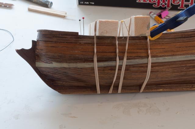
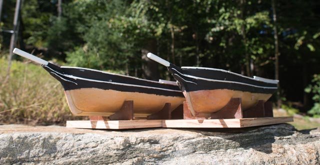
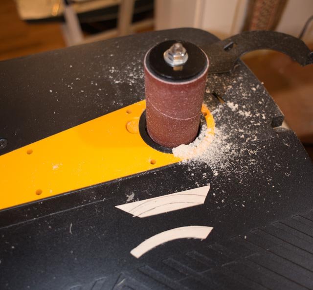
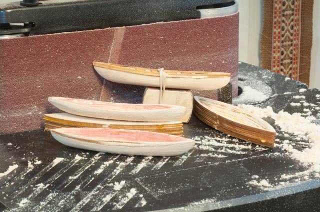
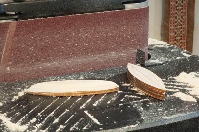
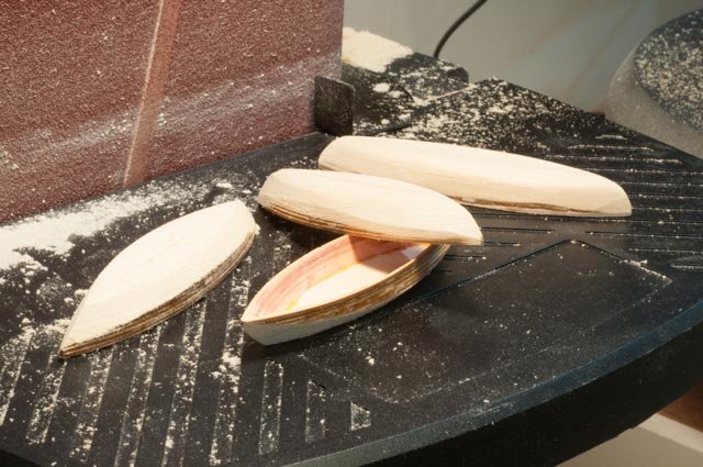
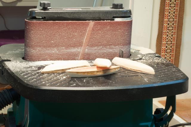
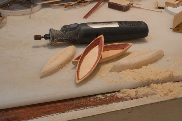
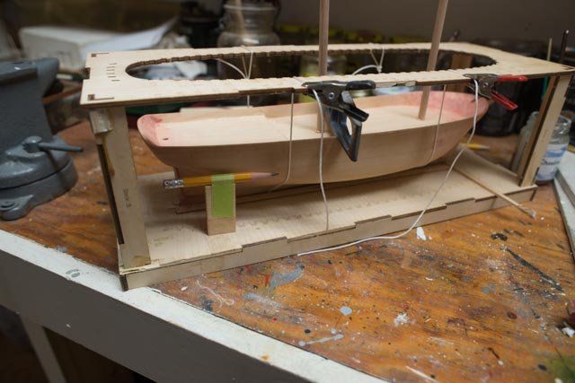
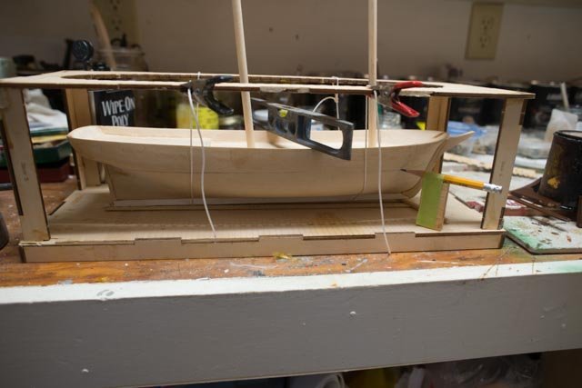
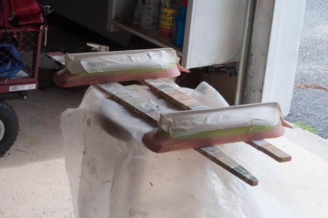
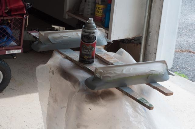
Some more progress, a few more issues and yes more fun. · I worked more to get the rough sanding of the outside of the first whale boat done. Now for the production. My newest shop tool is a great addition. This is a combination spindle and belt oscillating sander. One can order several grits and I did get finer for more critical future work as I am determined to enter the world of building frames. · Here we see the set up using the belt · For these little boats in just a few minutes of figure tip control I can roughly shape them · We then turn them over to the wireless Dremel small diameter sander for better control. Back to the two ships. We need to identify the water line and get a coat of black above and light poly below to support the eventual copper tape · I thought I was ingenious as I rigged up a POF frame from a schooner project of the past. A few calcs off the drawings and we are ready to go · Here we are where eventually we found a problem. On all past models I set them upside down and rigid. Here they are loose and swing on the string……let's see what happens · We have learned over the years that it’s all about the prep. Here we have used the glazing putty to fill in all the scratches and dimples inherent in the carved hull. After sanding with about 600 grit we are ready to prime · He we use the body filler primer from a local auto parts store. I love the flat gray.My friend uses it on his WWI navy boats with just clear coat Back to the whalers....It is time to start boats 5-8 while we read more about the full whaler in Ronnberg's book · Yes, the first steps go faster on boats 5-8 because it is only a few days ago that we learned how and not last year. I have learned the hard way that forgetfulness is a trait of our generation. cheers
-
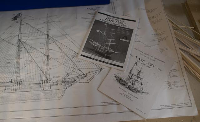
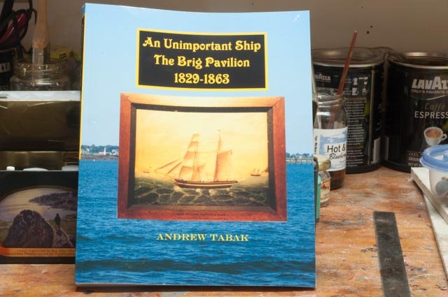
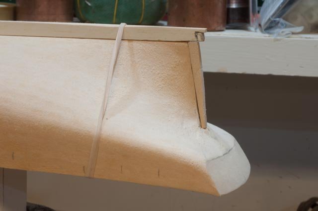
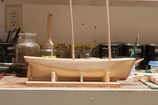
June 2022 edit Well it is time to sort this build out and make progress not noise. The ultimate plan has shifted further into the Boothbay, Maine vessel category. A few things to consider as I rationalize this change. I will do all that in the 18th posting below where I pick up the story. The short version is this build started as two sister whalers based on the kit Kate Cory. It will now be two Schooners bridging 1829 to 1902, both built in East Boothbay. please jump to post 18 below. if there is importance to the location of this log it might be moved based on the now 1829 selected date for the schooner version to best match the hull design. I will remove one of the hulls [ pavillion] from this log and add a second old schooner model in need of repair and retasking. This will make one old style schooner of 1830 February 2022. edit This edit including the change in name and update is to celebrate a final decision on what to do with this started project. Since working on general maritime history where whaling is clearly a big part, I have refocused my limited ability to the shipbuilding in our own Boothbay region of Maine. It is true that many Maine built vessels and seamen went to the whaling industry. In fairness I leave that to all the folks in that region. In my ongoing studies that will be parallel to the restart of this build will be study of the 32 brigs in Boothbay. This build will be planned to make the two brigs representative to two built here. I will identify the two later and plan to have them in a sailing pose. Parallel to that completion next winter, I will be planning a version of a brig on a scratch build. We shall either expand this log to cover all three or start another.....thoughts for another day. started project through 16 posts was to be . the new work will begin on planning over the summer as I complete another project, Dancing Feather. original log Two Whaling Brigs, Kate Cory and Pavilion KC Built: 1856 in Westport Point, MA Pav built in Ct and converted to a whaler in 1841 Length on Deck: KC 75 feet and Pav79 feet [ close enough at this scale] Models are model Shipway kits at 1:64 It has taken me a while to figure out what to do with two, yes, I have two, Kate Cory kits. During the last several years before I retired I would play each Christmas season on eBay and bid on Kits. Two times I won two bids for different versions of the same boat….oops I’ll share the other one in a few years when I move in that direction. What I got with those bids was one old 1994 version and one newer version with the 2007 instructions of Kate Cory. They have different parts provided and so far, and I found some missing wood. No big deal to me, as I have a good supply. The old paint kit came in one box. It was kind of sad, I’ll show it one day. One reason I got these kits is I have always had a plan to take a tangent into the world of whaling. That means considerable reading, some travel and yes building a few models. I am fascinated with the arctic and whaling is a big part of our New England experience up there. I plan to ultimately build a large cross section of one focusing on the process of rendering the oil. We’ll see where it goes. Now what to do with boat number two. I thought about rigging one as a schooner and the second as a brig, but the story seems to be that the schooner was not a successful rig for ocean whaling. In my early research I have found a book that tells the complete history of a 79-foot brig that first built as a merchant and then refit as a whaler. I bought the book and for now plan to see if yes that is hull two. I will start off as much of what is to build is affectively identical. Then other than the white strip and fake cannon ports see what could be different. I also have my other builds that all need work before next summer, so this is truly a squeezed in adventure. So let’s start out. I shall add in some of my research results as we carry on. This also my first down scale to 1:64 so I have some new skills to learn here too. · Here we see two books. As stated one was written in 1993 by Erik A R Ronnberg and the second 2007 by model shipways. The plans are the same. They seem fine for modeling at this stage though lack many details. I have read in other blogs that until recently the New Bedford Whaling Museum would sell the Erik Ronnberg multi sheet detailed plans and booklet that would be needed for anything larger or more detailed. I want to pursue them but so far, no success. I hope to visit the museum over the next few months. · Here is the book I bought giving a full life study into the 79-foot brig Pavilion. For now, I shall plan to try match up some colors from other brigs of the time [ though guessing at this point]. The picture on the cover shows the fake cannon deck and that is easy to include. This model is the first solid hull kit that I have built. For these early whaling kits I am focused more on what makes them whalers and how to work at smaller scale. I have so much to learn and it would take so long to build two hulls, that is why at this point I am happy to try it out. I was very impressed that after cutting out the patterns [ only available in one of the kits] I was to find that both hulls were pretty good. They advertise correctly that the bow and stern need work and that is true. They also advertise that cutting the bulkhead was to be the most difficult work. To be honest, now that I have done it [sort of], and now I see we are planking both plank shear and whales on the upper topsides, I would recommend cutting off the bulkheads and building them up in proper thickness. I will show you my compromise for this build in a bit. · Here the aft end is shaped up and one of the stern posts is set. I also drilled the hole through for the rudder post. · Here I completed one of the fit ups and added the rough masts and rudders to take a look see. Now to get going on those little whale boats. My Bluenose dories did not come out well and someday I need to rebuild them. First, I plan to go through whaling boats. With two KC’s and Charles Morgan followed by the big ¾ whale boat I should get there. As in previous builds, making one hundred turnbuckles, multiple spars etc I try to set up some form of production line. I do it not just to get through, but I assume by the last part I get the hang of the task. Here I have eight boats to make. I would think the 8th boat to be easier than the 1st. let’s see · Starting off both kits use the buildup lift method. My plan is to move through four boats one step at a time. Then as I get it figured out expand to all eight before I forget it. · Here we are making progress getting them set up; the insides are shaped using a wireless Dremel, file and sandpaper. I added some glazing putty as the fit up of the lifts inside was not great. I sanded again and put the bottoms on. I just started to rough sand the outside on the first boat. More on that process next time Cheers
-
Rich I am entering whaling as a whole new area. I plan to build a few kits to get the hang of it. Kate and a sister brig....you'll see what I mean... then the Charles Morgan and a large whale boat...3/4 scale I believe. I love the process of studying a real ship and Mystic is so much fun to visit. During these builds, at 1:64 scale, I hope to learn new skills...….. and following others advice I'll be working on more sailable boats like the BHOD one designs, my existing marbleheads etc. and a 3/4 scale schooner I never finished. The open question is what to scratch build …...a sailing whale ship model or a large cutaway showing the insides. As to making a sailing model, Kate Cory as a schooner would be easier at 1:24 but the more I am reading the Schooners were not really good for the process of whaling. I would love to figure out how best to rotate a foremast, so that is on the table. Also holding me back with KC is the better plans that used to be sold by Bedford museum are not easy to find. As to ship insides, I would love to build a POF version of something and then open it up. anyway it's all fun. I started to gather photos today and plan to get posting in a week or so. I also have the Halifax model on hold and more to do other models. cheers jon
- 109 replies
-
- 2
-
-
- model shipways
- kate cory
- (and 1 more)
-
I am envious of your trip to New Bedford museum. I went to Lunenburg twice while building Bluenose. I am in research mode now as I start my build of Kate Cory. I enjoy you log too. It is so important to see how others have interpreted the details. The plans are limited in details. I'll start my log soon Cheers Jon
-
David I want to watch too. I have a few projects ahead of this one and then want to build Kate Cory [ as a schooner] and then Charles Morgan. I loved visiting Mystic a few years back; there is so much information there to help figure out how everything works. cheers
- 145 replies
-
- 2
-
-
- model shipways
- charles w. morgan
- (and 1 more)
-
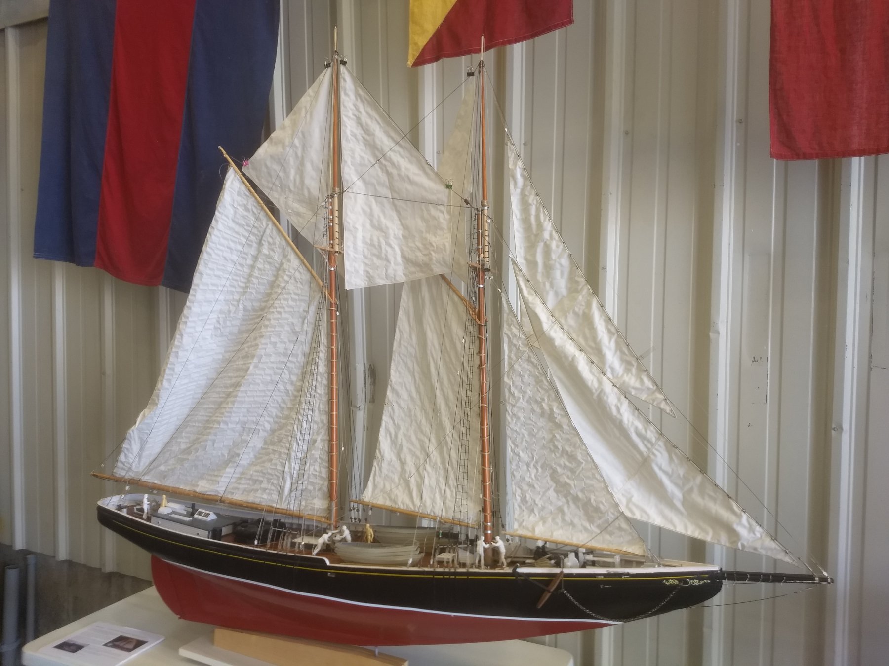
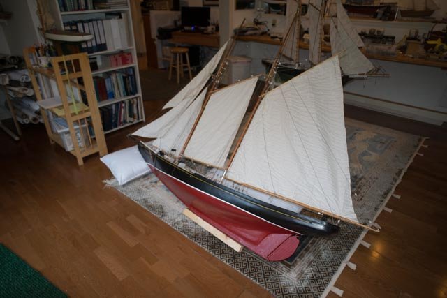
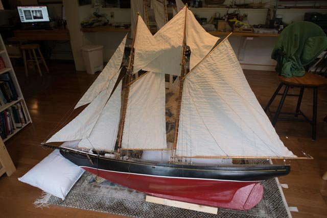
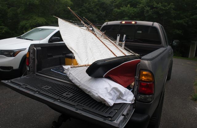
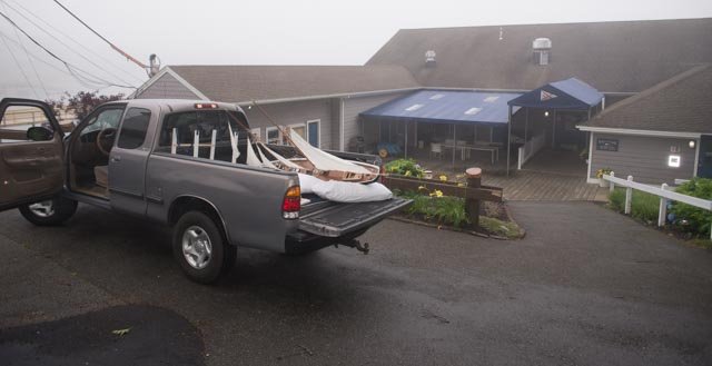
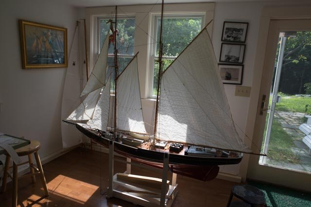
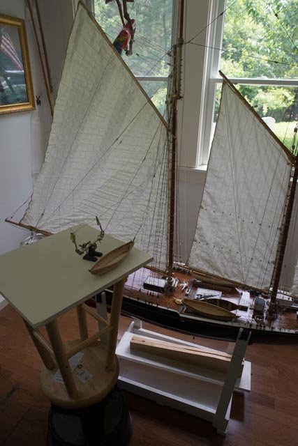
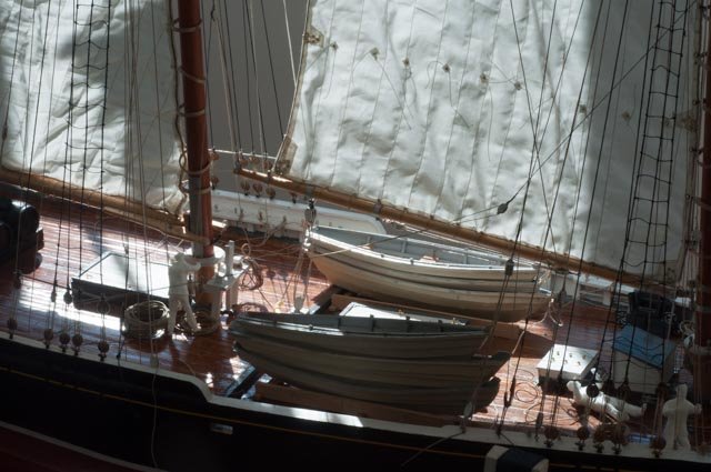
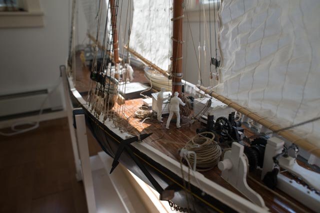
I want to update with the logistics I encountered in trying to be able to move this big model. I must say it was a bit of help from my skipper that solved the problem of movement. First up was to lay her down and add 2x2 over the sailing keel bolts. Looking at her I felt I could not show her half dressed. My daughter was here for a racing weekend , but we were fogged in. We took a rain day and she helped me complete rouging out the three top sails. We pinned them on and said "yes"... she goes with all sails in place even if they are pinned. My Skipper's son just happens to have a truck....it takes a village someone said With flashers going we drove one mile down to the Yacht club at 15-20 mph and made it.. The mainsail was flapping and flapping but held up. We got her inside where she stayed for a week. We gave a lecture one night on the racing history and modeling of Bluenose. lots of fun. We got her home and only one jib topsail sheet ripped. Last week we took her 2 miles further down to a boat yard on Southport Island to be displayed as part of the summer art festival. Again we had lots of fun. Now as we look in these views it is easy to see the need to replace the main and jumbo. winter is coming. Just like the Ironsides in Boston, she went out for a few trips in the harbor and when returned to the dockyard is reversed. the winter sun will shine to the starboard side this year. More importantly the port side is now exposed and ready for its ratlines and other work. cheers

-
Michael thanks for dropping in. my next post shows her as close the water as I fear she will get. I have gone too far both in construction and detail to sail this one. Moving her is also a challenge. cheers
-
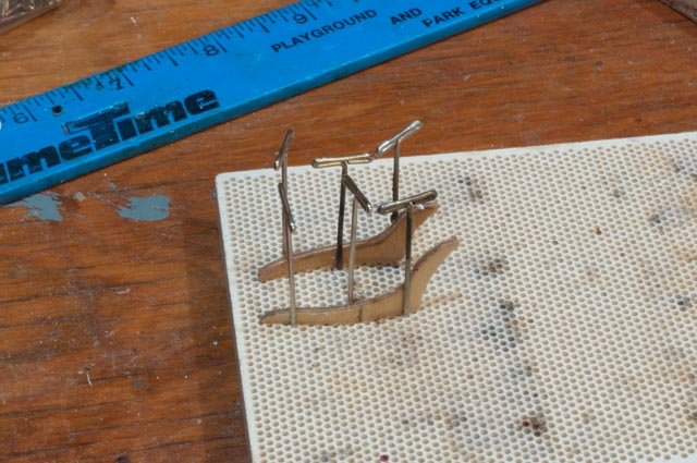
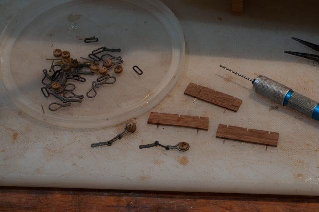
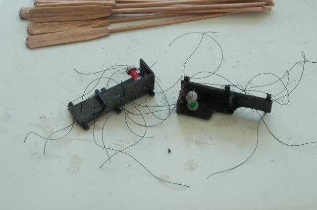
This update is just to record a little more work i was able to do before summer sailing and outside activities hit. I decided to set up the dead eyes. i found the kit came with reasonable parts..but Here i am assembling the set up. i believe i shall paint out the wood work black bit want to see it first. oops i broke two pieces. fortunately some how i have this supply of miscellaneous stuff and was able to rescue. i will need these when i get to scratch builds. so the rescue made, simple pins added for strength and we are ready to install lI definitely plan to paint all black. port side done starboard done and resting until fall cheers
-
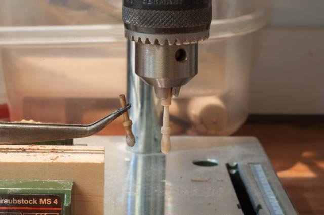
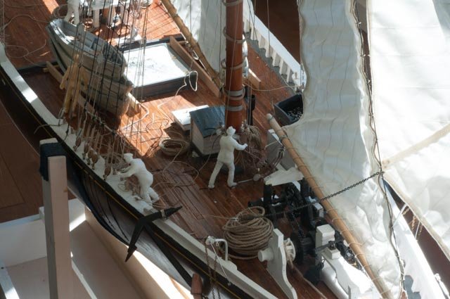
It is now July and I have to figure out how to take Bluenose to the yacht club for a talk in a week. Today I want to update the flurry of work I have done to get ready for the first showing of this project. The more I do, the more I want to redo so the saga continues. One thing I have learned is how to do rigging close to the boat. Obviously whenever possible I go to the table and do splicing etc., but often we have to run a line through a block and then splice it. Let’s see some of the cleanup and progress I have done. Here I have set up a table to allow reeving and splicing lines for the dory tackle. One can also see ratlines are now complete on the starboard side I have decided to clean up the first horrible prototype dories I made and use them as place holders. I have a new spindle sander and that is an amazing tool for shaping planks. I will need to rebuild at least 4 of them. Here we see the [ temporary] dories all panted out and stacked. Amazing what paint can cover up. Also, note the dory hooks lashed to the rail. I needed more belaying pins and decided to make them. The small drill press and a light touch with files made it quite easy. I would say about five of eight make it through un broken. Surely a harder dowel would be more successful. I also needed to make up the running lights. I used two sized dowels, cut the top with the spindle sander, drilled through and set three disks on a pin for painting and eventual gluing. I have been reading about LED lighting so look out. My son visited and showed me where to buy correct era merchant men figures in white to add to the crew. I also redid the main anchor line. Here the port running light is in, the lines are on the top dory and the oars are laid in. also repaired down hauls, installed missing boom lifts and completed the ratlines on the starboard side. so clean up , preparations and the move. cheers
-
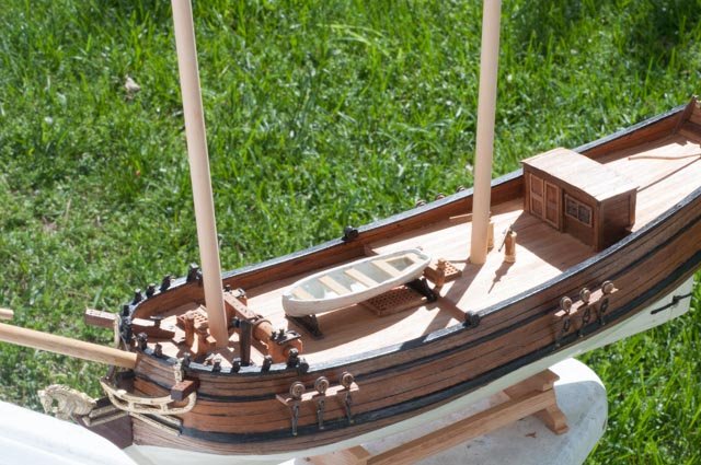
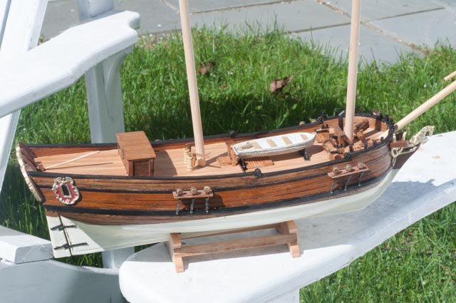
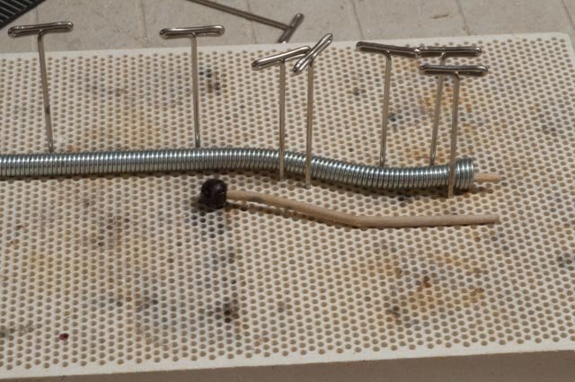
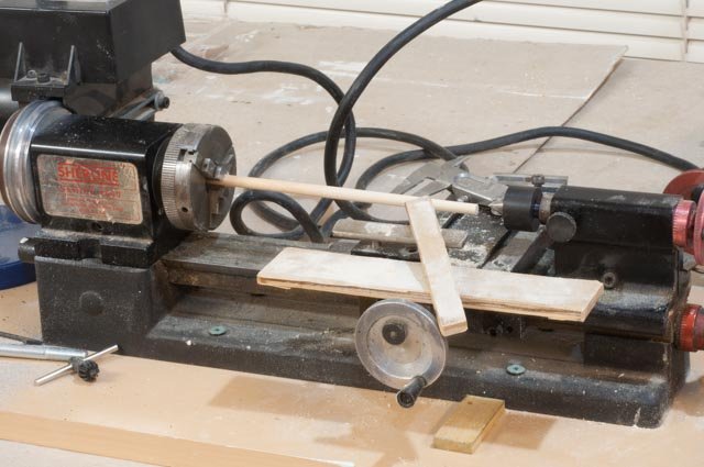
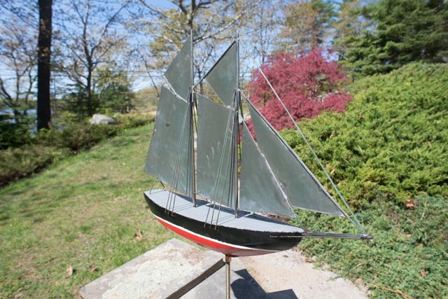
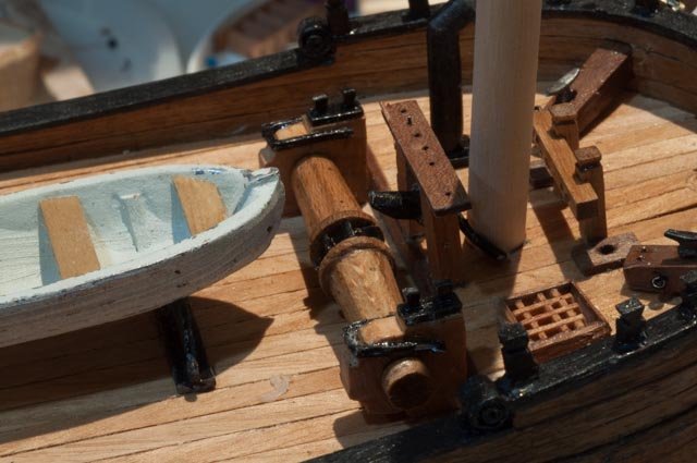
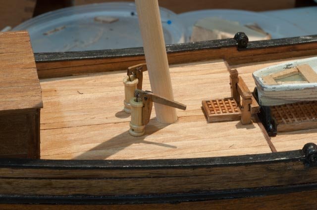
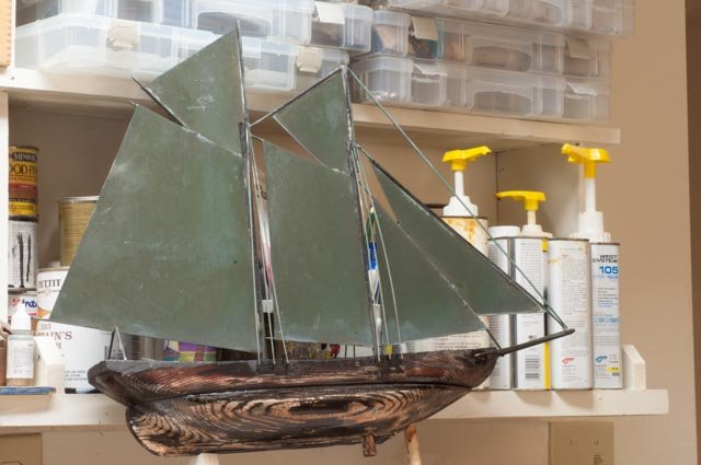
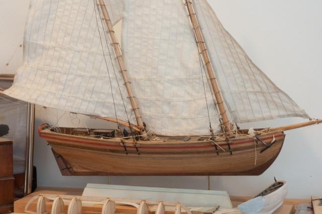
It has been some time since I have been able to sit down and write a little update. for the record....As spring came we made our annual trip to Arizona and extended the trip to visit more family in Colorado. Then we all know that spring fever hits and we were off to the garden store, checking on getting the boat ready etc. Thus, modeling is not happening as it might. I have decided that I shall use the Kit materials in the maximum as I am studying the boat and learning about the rigging and sailing. With a little care I think they are working out. First let’s get out the lathe and sanding boards and make up the main spars. I find the dowels provided are all MM dimensioned so the fractional inch chuck don’t always work. Not a big deal Here is the bow sprit. I followed with the two masts. Here I dug out some spring tube benders and used them to rebend the wet tiller. You can see the first one with oversized ball was bent on pins and that does not work too well. One of recent diversions was a fun interruption. A ggod friend was cleaning out her home to move back to Vermont. She found her grandfathers old schooner weather vane. It was a wreck. The twoo wood hull sections were apart and the long weathering had deteriorated the spruce pieces. First of all I removed all the paint. Then in this view I have epoxied the two haves together and put on the first coat of resin over the whole thing. The resin was totally absorbed, and I ended up putting about four coats to get it secure. Here ware all done and outside for a first look in the sun. I previously had nothing on the deck remaining of black paint, black topsides and white bottom. With approval I made a more traditional color combination. I hope it takes good Maine memories on its trip to Vermont. Back to progress Here I have set the spars loosely and built out the deck furniture I went around a few times on considering building the masts as they would have been before the Navy changed them. I decided that in my plans to scratch build some of these schooners I shall defer that to those boats, so I can have this one to display the different rigging. Therefore, the mast is trimmed to the right height per the plans. I must say it was the use of the fancy windows and the horse that convinced me to stay the course and build out the kit.......as of now no guns though. we'll see that would be rework on the bulkheads...something to think about Here is view of the deck with almost all of the fittings in place. I used almost completely the kit material. One of the little doors went missing so I made a new one. Of course I found it as soon as the new one was in place. Here looking from the port quarter angle, we see the fancy windows Here we see the windlass made up of kit parts. Also note I simply have placed the cast boat on board. Some day I may chose to replace that but for now it is a placeholder. Here we see the pumps and I actually believe this kit part is quite good, so much better than castings. All for now Cheers
-
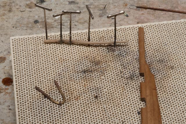
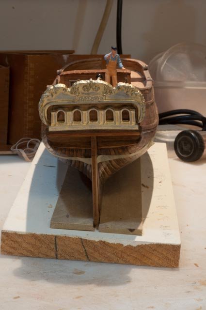
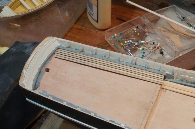
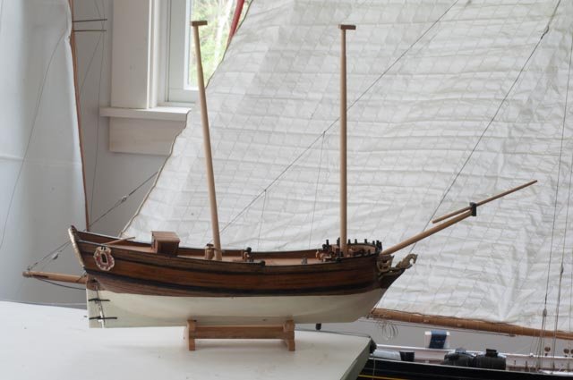
OK it’s time to decide …and I have · Here is a photo of a 1800 Virginia pilot schooner kit I made a few years ago. It was fun and a good kit to learn a few things. The wood was good quality and despite my amateur errors looks good. It could have been painted out, but I left it natural. back to Halifax pre HMS navy chnages.. I took off the shellac some more and felt there was little purpose. Even the pear wood is not beautiful. So…….. · I have put on about 5 coats of ivory. I have taped one side of the wales and plan to paint them black · Looking closer we seem to keep the planking look. The shellac did a nice job of filling the gaps not up flush as a paste filler would have done. · Our roses are in place so a little filler here is needed · Here is the first coat of black. I did this for a look see and if I did not like it , the acrylic comes right off. During this time, I used a scalpel to scrape all the shellac off the pear and walnut planking. · I also started playing with the transom paint. · Here one can see the result of patient scraping get off the shellac. I must say I agree with e advice that using the shellac gave a good infill that looks brown/black for pitch. Before finishing, the pear is nicely ‘yellow’ tinted so my decision is to keep going with natural topsides. · Here I have applied glazing putty. I also cleaned up the fore deck rail [ 5 laminated planks had some rough edges] and a few pin holes in the cap rail that sanding did not completely sand out. · Here is coat one of rub on poly. The pear and walnut become much closer but with the black wales I am OK with the look. I imagine a lesson learned is that to get the better planking wood , we need to get our favorite suppliers to substitute what comes in the box. I don't complain too loudly as i my have contributed. I believe the black markings in the wood came while planks soaked in ammonia water softening for bending. Kind of like getting those dark water spots out of a real Sitka mast or boom after years of ware. · When including the contrast of the top side inner bulkhead, a mystery wood I had in the shop, and the light decking, it is time to stop thinking and move forward. · Here I have gone back and repainted the black after another coat of poly. · With this view I am moving forward. I am sure through the process another coat or two will be needed. Cheers


-
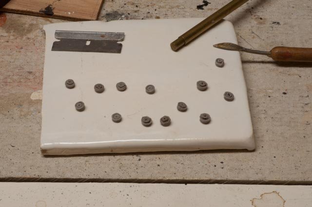
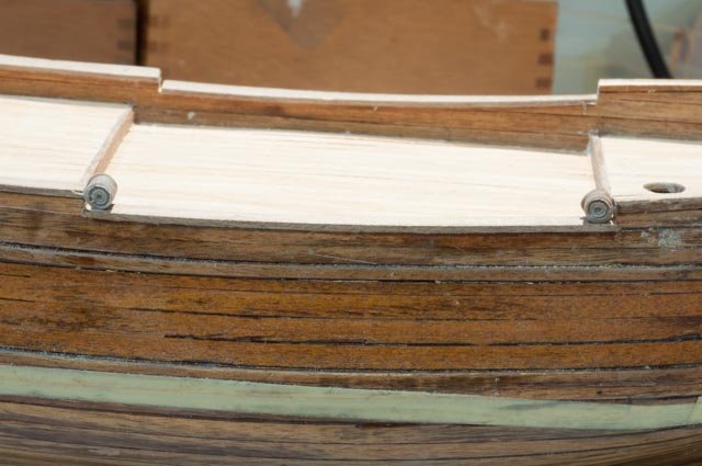
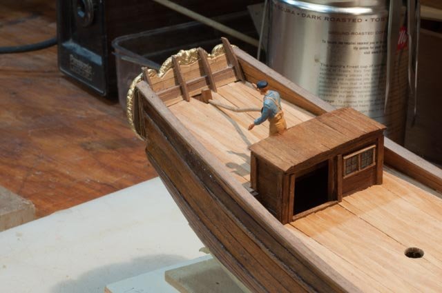
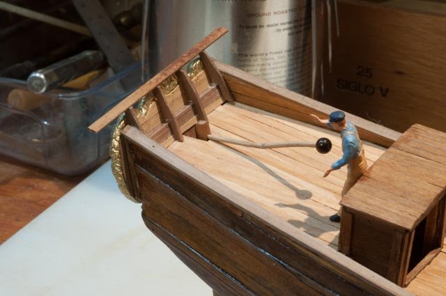
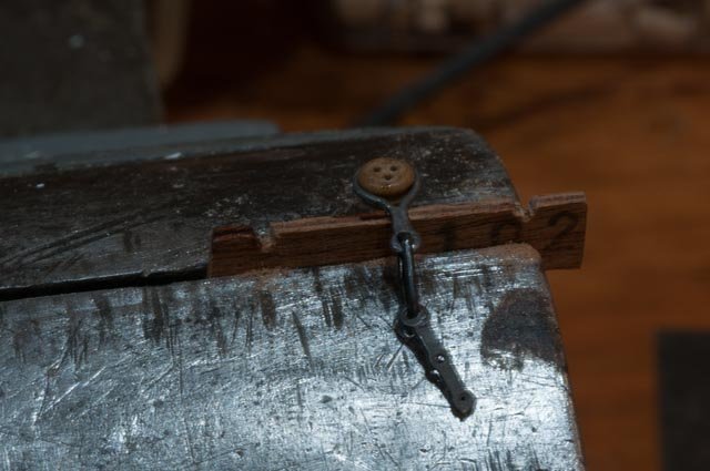
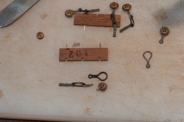
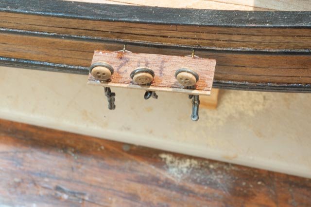
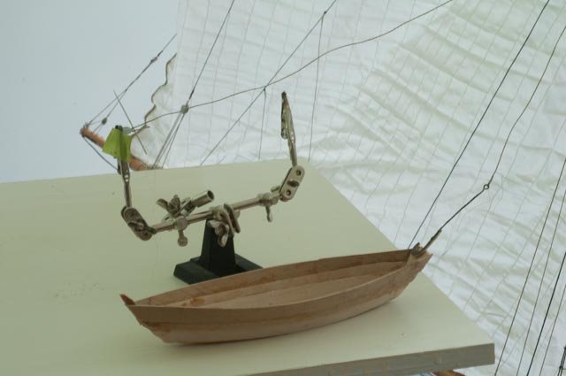
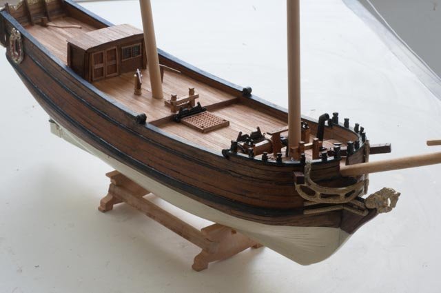
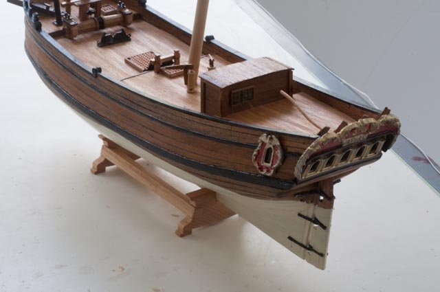
This update includes a few miscellaneous items as I move along thinking about direction in making this packet schooner. First of all another mistake. A few postings ago I went through drawings and showed there was no dropped bulk head from fore deck to main deck on the Harold Hahn diorama shot of other schooners. I decided to add back in at the early stage as it is always easier to remove parts later……..I added in both structure and planking…oops. Rereading Chapelle, I find before and after views of Halifax. This dropping of the bulk head was not a change made by the navy on the original schooner. They simply added the gun ports. [ I won't] Looking again through several images I also found for the most part the schooners did have a dropped rail at the main deck. · Here we are with nice long shear and rail…..the laminated rail on the foredeck is higher and it is just wrong. See the two saw marks as I start the fix. · I have dropped the bulkhead one plank and am regluing the rail · Here I am experimenting with the sculpy approach to making the nice little roses for the rail transition. I used a 3/16 brass tube with a 5/32 bar inside to extrude sculpy and razor off. I will glue two back to back after cooking · Here they are glued in place. · Now lets make a mock up tiller and see how the rudder fits · Here we see the mock up tiller and the build up of the transom with walnut to cover the metal. FYI the tiller broke at a bend. The pin was too sharp I guess and weakened the wood. · Note the side rails are too high as discussed before as the lowest wale is mis designed [ too high] in this kit. This shall be the test. Setting a board in place I feel it is ok to continue. Though I may rename the ship the mamoli . I think the bowling ball size bead is a bit big for our tiller. Also I need to leanr to make figures as this guy is definitely not 18th century · Here the transom is in place and the walnut planking around it. I need to paint the windows out black and then think about mullions. I like to use pins [ wire] The kit gave me cute blue infills decals with red mullions….no thanks. Next I need to get off the shellac and decide on the hull finishes Cheers