


Jond
-
Posts
758 -
Joined
-
Last visited
Content Type
Profiles
Forums
Gallery
Events
Posts posted by Jond
-
-
Post 25
Complete the decking
A little celebration was held, as I finished the deck planking. I now need to start the sanding and rethinking about finish. We had our monthly guild session, and it was fun to get the input of diverse ideas of how to both finish the deck but then how to make sails.-
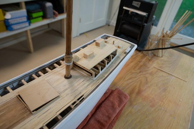
206
 here the planks for the raised foredeck have been sized and their outboard side darkened with magic marker. I must say I have enjoyed working with the Alaska yellow cedar. This has been my forst milling job and hopefully it will come out ok.
-
207
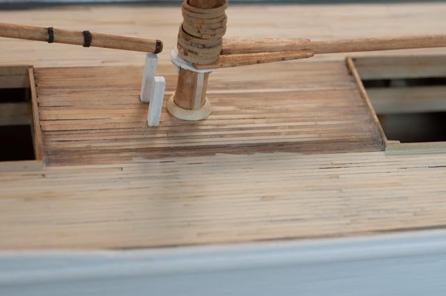 here in the mid deck area we see remnants of the experimental staining with “special walnut”. More on that next time, as I need to satisfy both historical reference, which is hard since images are black and white, and then the rear admiral, if I want the model to stay home.
-
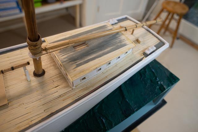
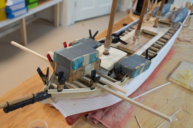
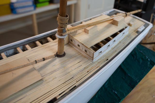
208
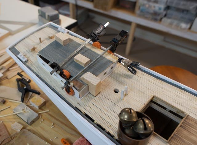 here we are working on the main cabin as the decking gets finished. The roof will be painted but I believe the material was quite similar as I follow the anatomy of book. The planks were shown to be just a fraction smaller, but I believe that difference would not be seen. So, forgive me for keeping the 4-inch size.
-
209
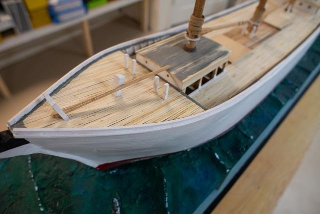 here the fore deck is done but not yet sanded
-
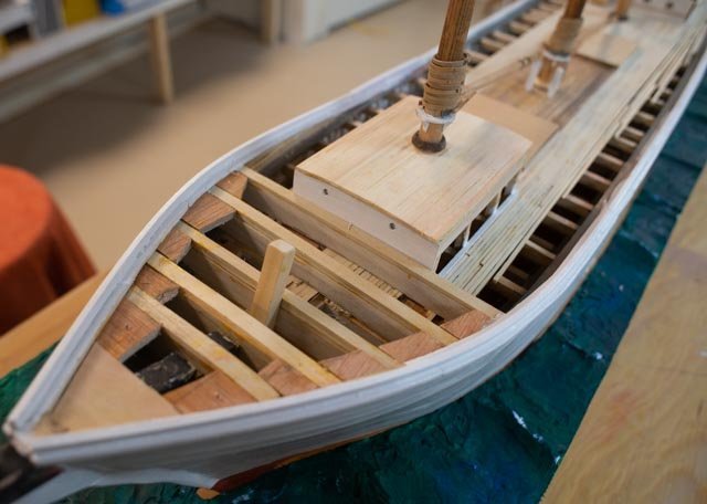
210
 likewise the after area is done but also unsanded
-
211
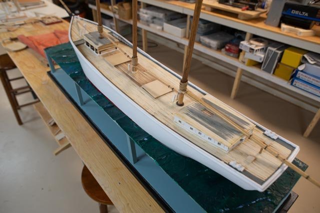 now for the overall look
-
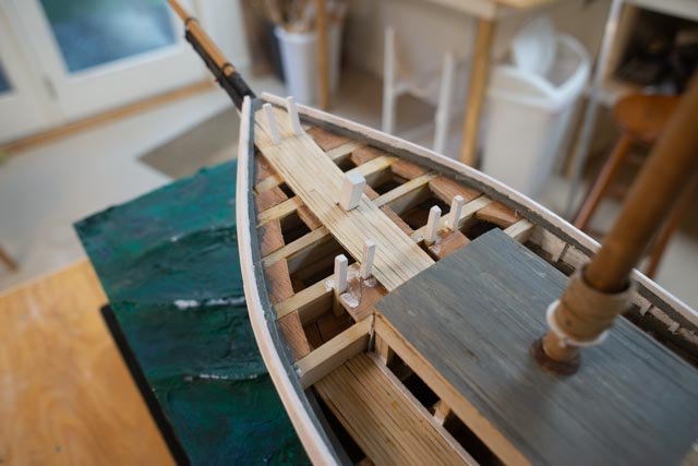
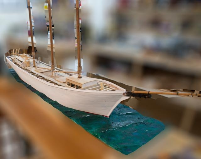
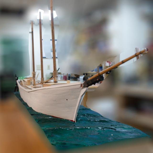
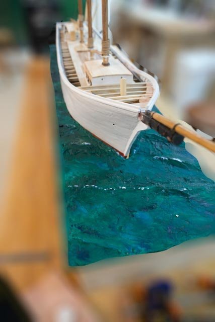
212
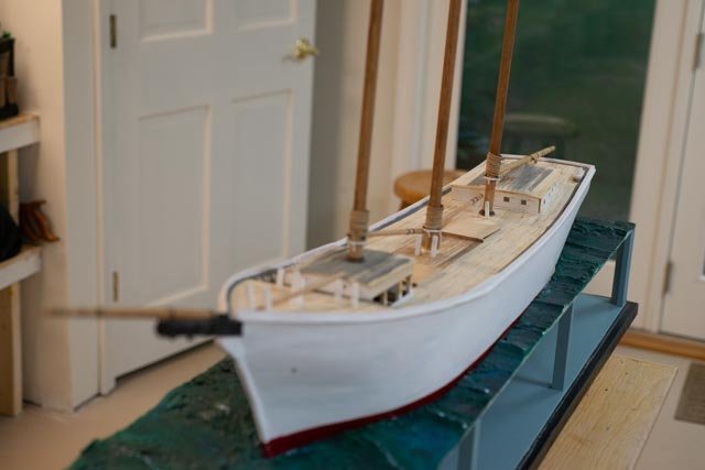 and here is the bow shot
Next up is sanding and clean up, some retouch up of waterways and staining the deck. I will then start the on-deck work, complete the cabins and hatches and the preliminary standing rigging. I think it’s fair to say we are sort of halfway home now. At some point I need a yawl boat too.
All for now
- KeithAug, GrandpaPhil and allanyed
-
 3
3
-
206
-
Post 24
Build the display
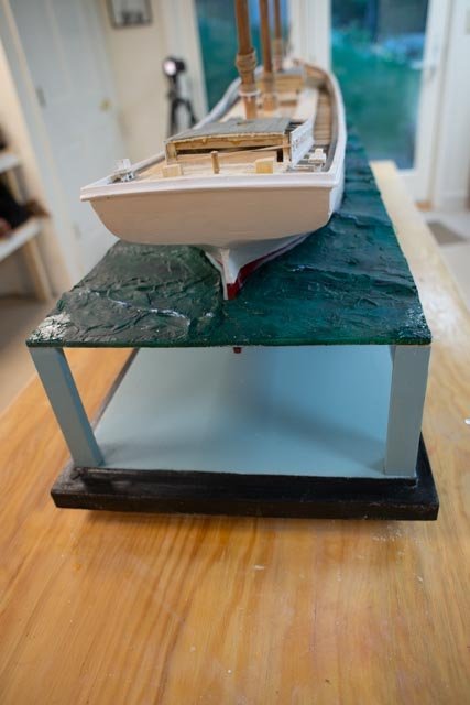
I may be ahead of myself, but I wanted to get my display built and ready, so I can set the Schooner in its final place while she is resting.-
200.
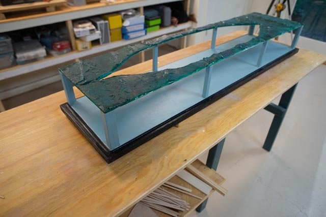 here we are all with the at sea system assembled.
-
201
 here we are in with Ada in place.
-
202.
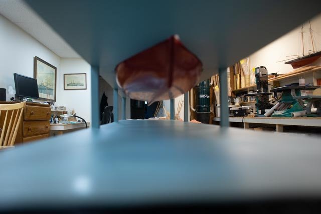 here looking below we see my attempt to paint out “water infinity”. The color, Jamestown Blue, is a bit of a guess. My thought is to use a little color but not have anything to take one’s eye off the hull.
-
203
 looking from forward. Here I have a new issue. The hull is basically flat. I did not shape the seascape opening for a slight heel. I will think about that as to alter it will involve both cutting into the one side and adding on to the other side. Sounds like a wintertime study.
-
204
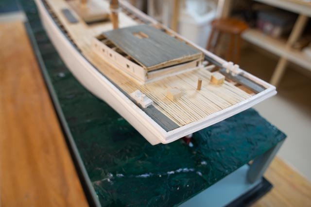 looking down from the stern we see some progress in the rough in decking and cabins.
-
205.
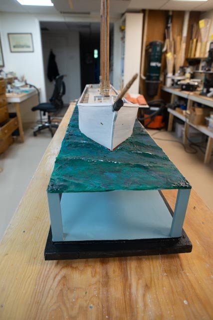
 and here we see the new raised foredeck coming together.
Cheers
-
200.
-
Keith
Glad to hear from you. I followed your turnbuckle comment and did go back and catch up with your build. I am thrilled with your comment but admit clearly there is a very long gap between our turnbuckles. your machining, fine soldering and fit up of consistent components is just incredible to watch. the idea of jigs to make such components I will take on board. the example of placing the metal inside a piece of wood and then sliding on the table saw for controlled consistent cutting was inspirational. I am constantly struggling with that process. as an example I do all the filing and cutting of the turnbuckle barrels by hand. I have a milling lathe combo from Sherline that i inherited from my brother, but no real skills to use it. I saw you were doing very tight bends with tiny brass rod. I keep using copper and mixing it with the brass.
there is just so much to learn. Thanks for your kind words and inspiration to go catch up on your work as it will surely help me.
cheers
-
Allan
thanks for the follow up
I suggest through your work with Ernestina Morrissey. you have joined the ranks of Schooner lovers. I hope it keeps bringing you back
the photos and books are fun to search for and through. I hope to get into that some more as Covid allows us to get back to the historical society this fall.
cheers
-
Post 23
Turnbuckles and bow finish
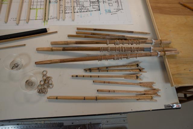
I need to get going with the few production items. These are the things that I will either make or procure and adjust like blocks. Turnbuckles need to be made. Only radio sail ones seem to be available. I also want this build to develop my learning, so the previous version is improved upon. I shared those images before.-
190
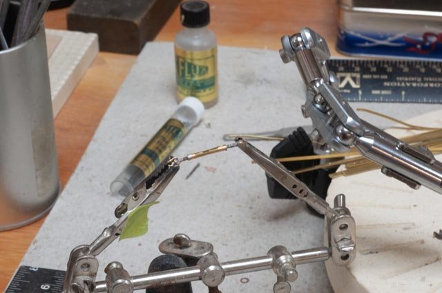 here we are putting together an assembly based on that previous build.
-
191
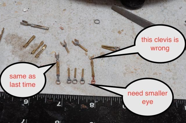 here we are looking at it. I tried to make a smaller ring by bending copper wire, but that won’t do. I want to see the threads that the little machine bolts have. Even though one of them will be backwards.
-
192
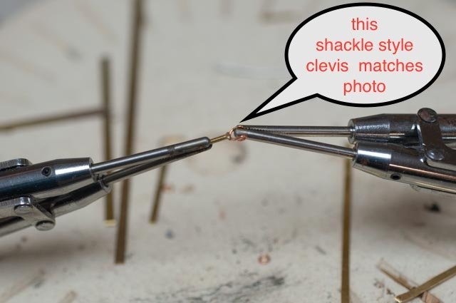 as shown in early posts, the top clevis is more like a shackle with the wire rope spliced around the pin. The thimble will be solid, but that detail is much later.
-
193
 I have taken some 22-gauge wire and made rings on a few size drill bits. I like this size.
-
194
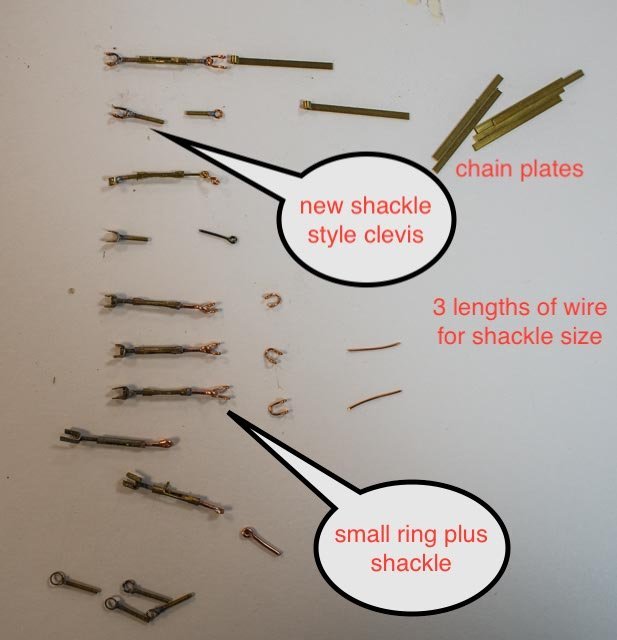 here is the saga. Moving up the photo we see that the lower ring fitting has a shackle for the chain plate. I made three sizes of shackles and chose the middle one. At the top the new parts come together.
-
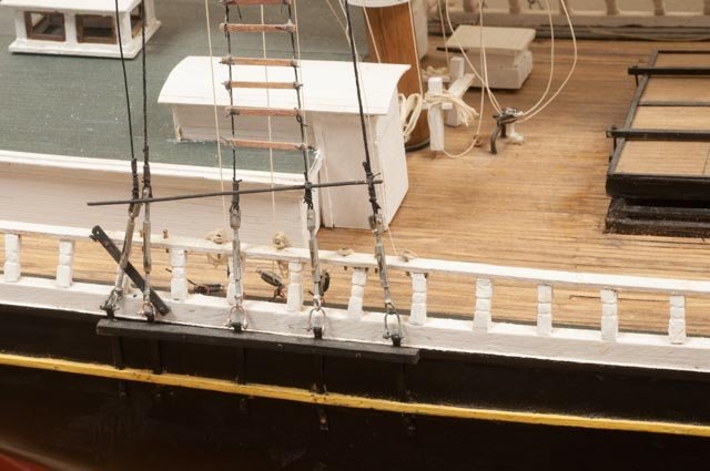
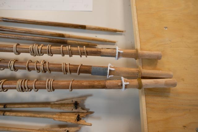
195.
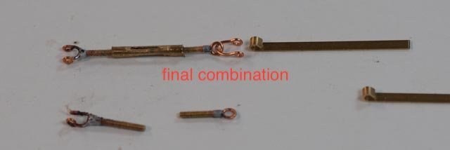 here is my prototype for the chain plate and main shroud shackles. Now I need to make about 60 of these. Hopefully we’ll be OK. They need to be galvanized then dirty. More on that later
Just to show I have decided to backup and redo the hull finish. A colleague at the Downeast Shipmodelers Guild in Bath had shared with us a few years ago, that a big mistake often made by us newbies was being too delicate with our sanding. He told us take it back down and do it again. That was specific to fiberglass over wood in RC models, but the theory needs considering.
-
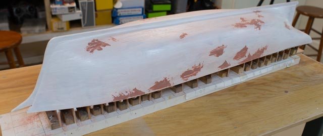
196.
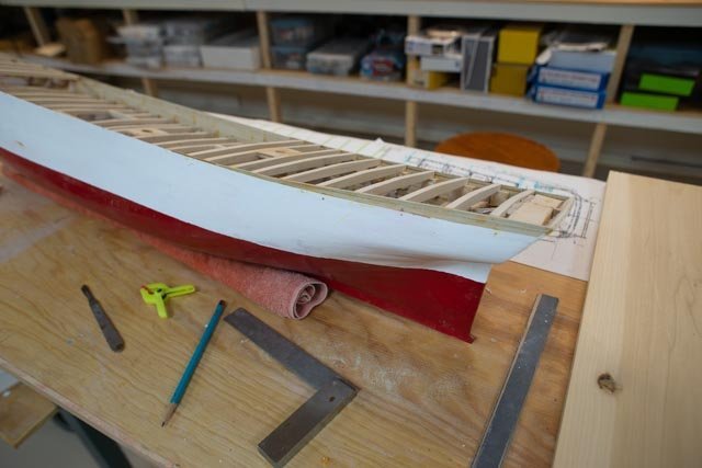
 I got a new utility tool last winter to work on a flooring project and used the sander attachment to take the hull back down to the wood and now can start over with painting. The long stretch with fill is unfortunate. It is there where the unsupported bulwarks were built independent of the main hull molds. If I had understood that the deck was raised, the molds would have been extended and that deformation would never had occurred. O well.
-
197.
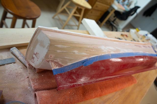 the transom also had added planks that protruded a bit and needed rough sanding to come flush with the remaining planks.
-
198.
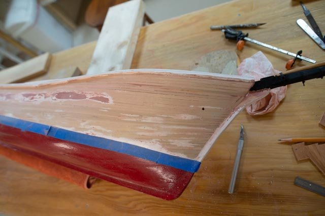
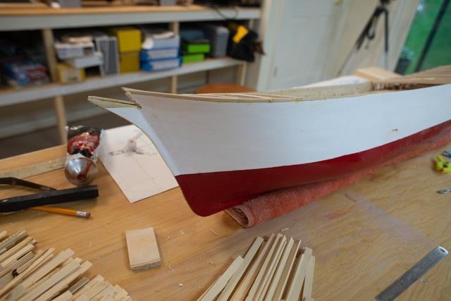
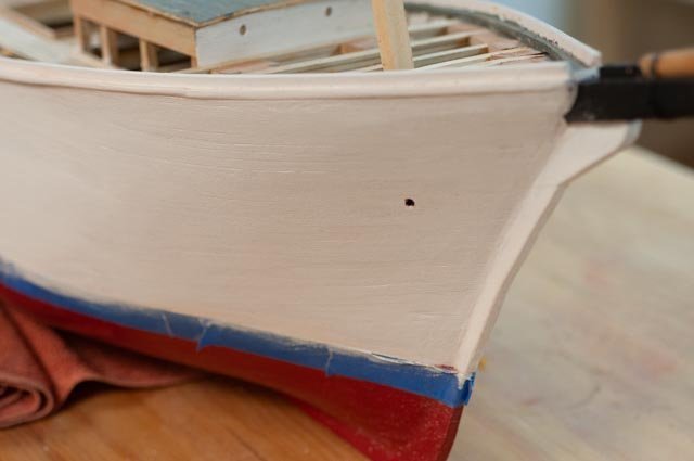 here we see the new bow. Back to an early post, I expressed my desire to see the planks through the paint. This is no museum piece, but I think I got the look I want. I put some exacto knife slices through the filled area, and that came through too.
-
199.
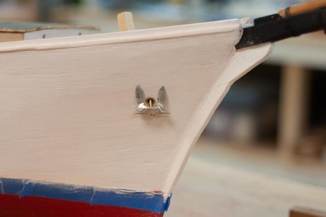 I thought for fun to see what the anchor will look like. I happened to have this anchor from Bluejacket in my stash of extra stuff.
All for now
- Roger Pellett, KeithAug, ccoyle and 1 other
-
4
-
190
-
Post 22
Fixing the bow
I left off having figured out a plan to fix the bow to follow the shape from the photos. It had to come up another 3 feet in scale , so here we go. I had already raised one foot form the bath schooner plans, so the total is a four foot raised deck over the windless.-
181
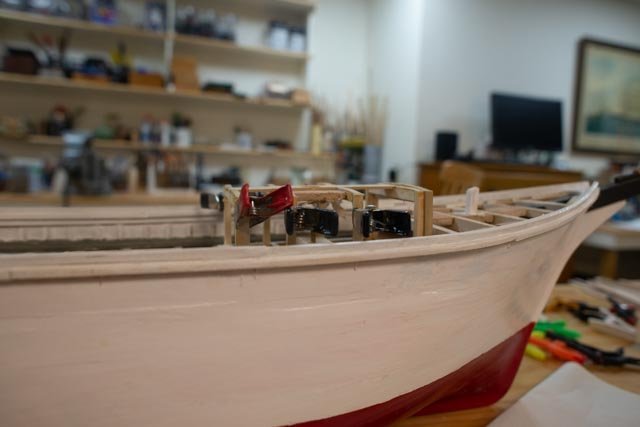
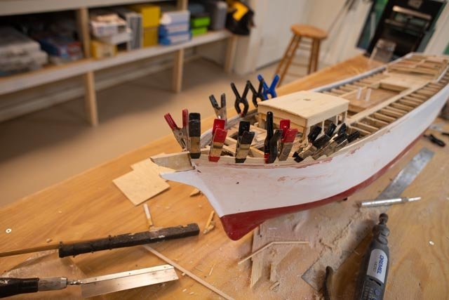 I built up the planking on both sides.
-
182.
 it took quite a few planks to get there.
-
183
 here we are gluing down the chock rail.
-
184
 I continued pecking away at the decking in the aft area.
Now a few fun photos to see where we are and where we are going. I painted up the sea, and added some blue tint and white highlights. I also painted the starboard side with a satin white to soften the hull a bit .
-
185
 we see a normally preferred view . wow if the sea could be two feet wide wouldn’t that be fun.
-
186
 this view is like the main historic photo of the launch. The high bow is now much more like the photo. I think though I need to consider a rough sanding and start over of the hull finish. This close up view leads me in that direction.
-
187.
 here the forward deck supports are mostly in and the new Sampson post is set.
-
188
 here on the aft cabin we have some walls ready and the deck coming forward. The decking is now another area for sanding and clean-up work before staining. I also need to guess what color for the deck roof. I am thinking to use the same dark gray on the waterways .
-
189.
 this photo shows what will need to become a preferred view due to the narrow confines of the sea. I will need to take several shots and blend them for enough to be in focus too, as this wide angle lense does not get enough depth.
All for now
- KeithAug and GrandpaPhil
-
2
-
181
-
post 21
onward with the second part of the deck oops fix
I had to chuckle again at myself as I got ahead of myself on the fore deck. As I progressed, I just knew something was wrong. The gas engine that is in the starboard side of the forward cabin needs to lead a chain forward to run the windlass. Men must get there and receive the anchor chain and drop it though a deck that is below the high foredeck. Thus, there must be a break in the deck and the foredeck must be higher. Further observations of the launching photos helped me come to what I finally hope is the right solution.
Before we get there, I did some more deck work.-
172
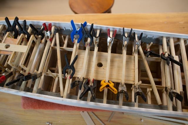
 here we are replacing the center section of decking to get us back to where we thought we were a few weeks ago.
-
173.
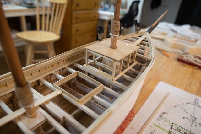
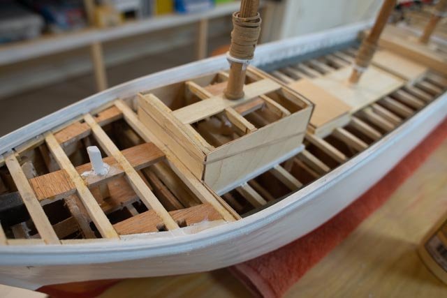
 here based on that review I rebuilt the fore cabin to its corrected height assuming, as the Bertha details show, that the deck carries under the fore cabin. In this photo we see I got ahead of myself adding bitts and things. They have all since come out.
-
174
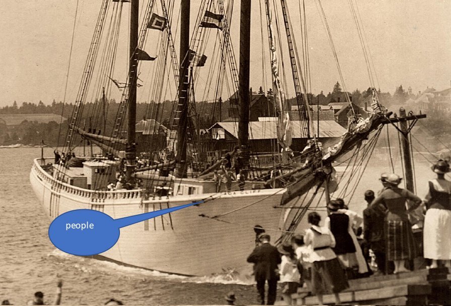
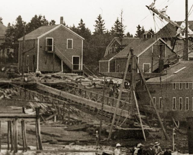
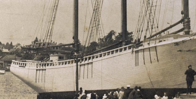
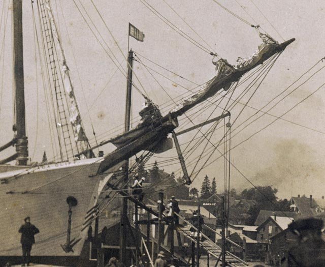
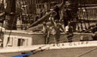 here is an extreme cropping of one of the launch shots. One sees clearly the people standing on the raised foredeck and the top of the forward cabin is waste high.
-
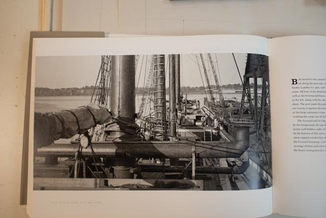
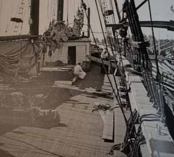
175.
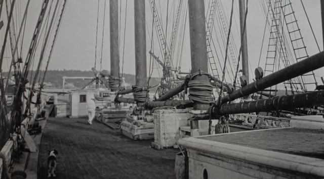
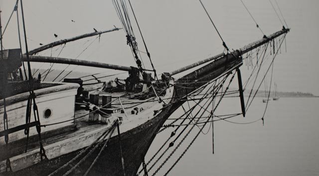 here is a good shot from the fly rails book showing the fore deck relationships that were so typical. The floor of the fore cabin is clearly 4 or so feet down. That allows the equipment to drive the windlass that is located below the raised deck.
-
176.
 here I am OK to continue work on the after-deck area
Finally, the solution
-
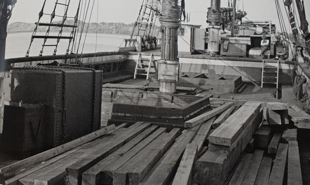
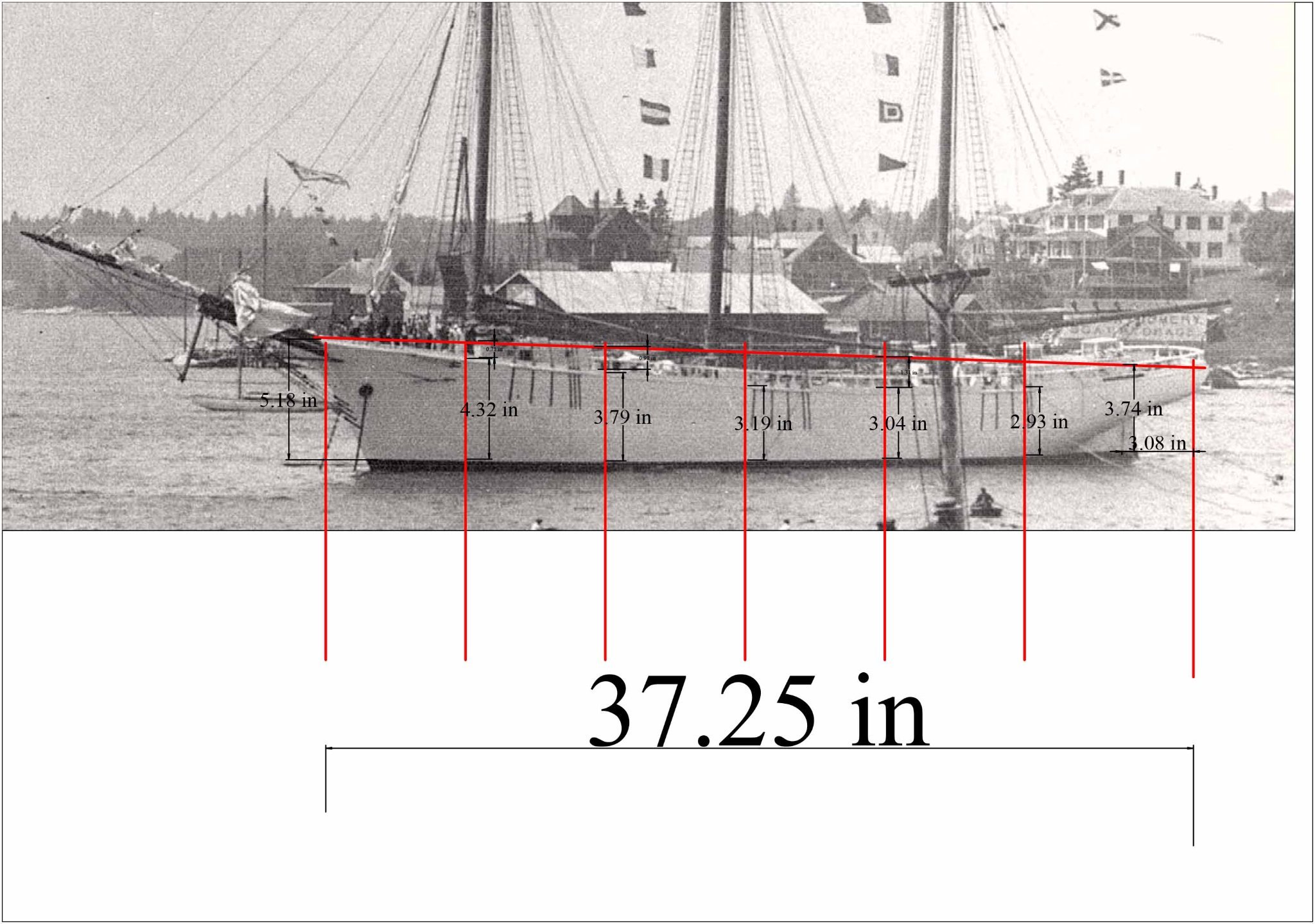
177.
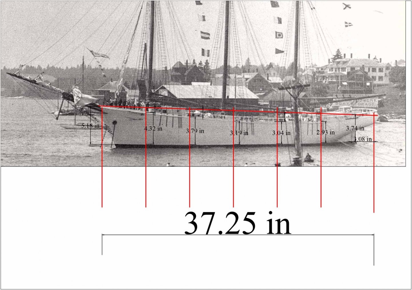 I took this photo into Turbo cad and scaled it to the full model size. I set verticals at 6 inches spacing and measured from the water way to the water line. When I checked the same dimension with my current build….
-
178
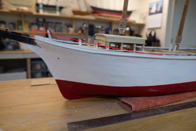 here we are looking at the current front shear line. We must remember we built this as a Bath built schooner and only have these photos to consider making it a Boothbay Schooner. The late Jim Hunt shared with me his findings that he Boothbay Schooners were known to have very high shear. Well, we just reproved it again. The dimensions that came out of the comparison suggest that I start tapering up the shearline to a point roughly ¾ inch at the line of the fore cabin to 5/8 inch at the bow. Oh well more demo…. I have already started
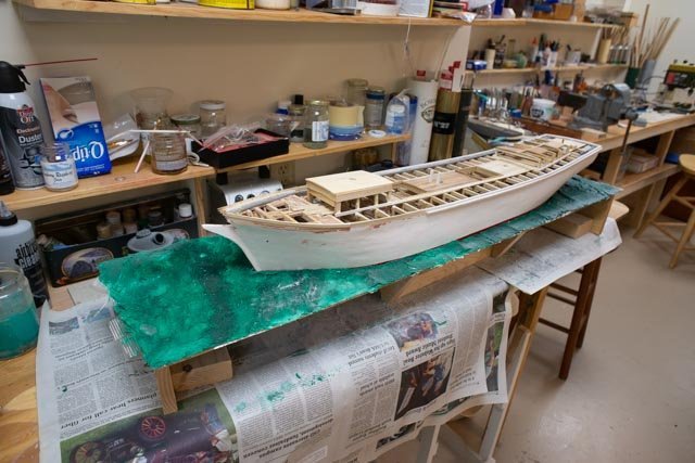
Fun with the display planningI am trying a new process to make a painted sea to carry the schooner. I have never done this and am not yet committed, but it is fun to try this process out.
-
179.
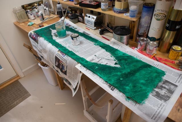 here we are painting out the shaped spackle sea with left over paint from the Bowdoin diorama. The can says forest green and being old is a bit thick. With my liberally adding water to the brush, inconsistently, I got a large enough variation to look something like salt water off a rocky coast. Next up it white highlights etc. I must remember less is more!!!
-
180
 Here is the first attempt to sit in the water
All for now -
172
-
Post 20
First part of fixing the big deck oops and starting production items
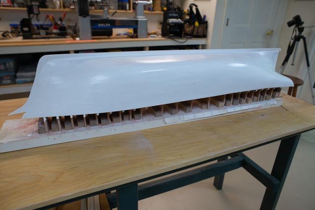
The first thing I needed to do after deciding to fix the big oops was to add the upper deck across the mid-section. I will worry about the bow later.-
157.
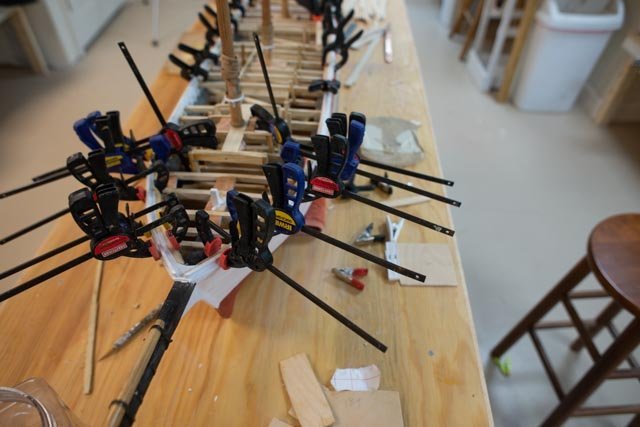
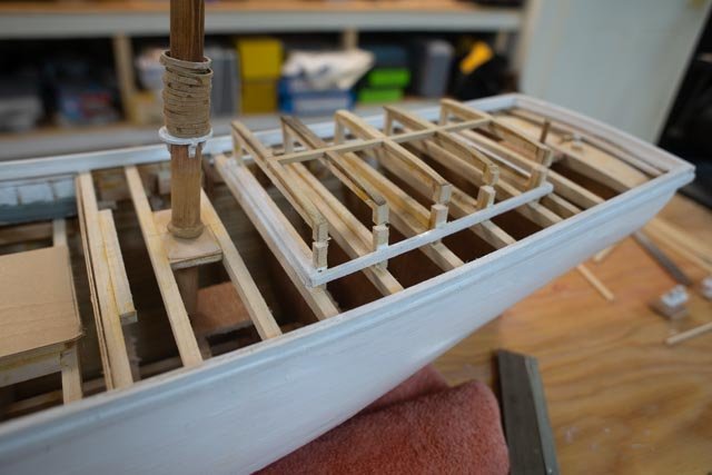
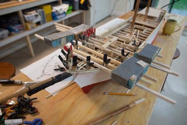
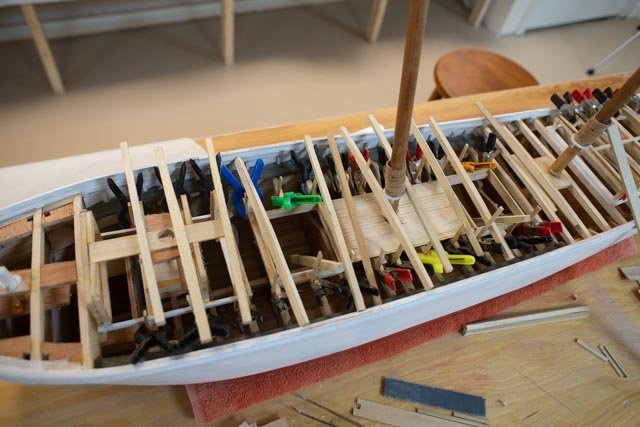 first up was to mill out, shape and set the new deck beams. The clamps are gluing vertical braces to hold them in place and add to future strength.
-
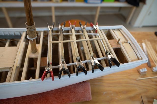
158
 here we are gluing the new deck beams in place.
-
159.
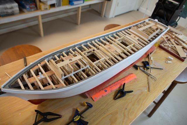
 this is the first view of the new overall effect of one deck.
-
160
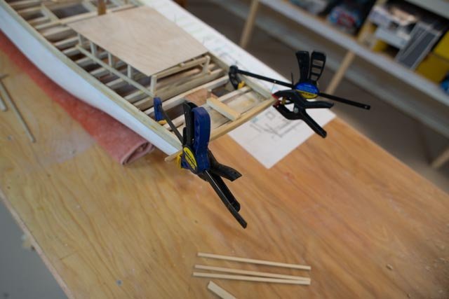
 here we are fixing the waterway at the bow.
-
161
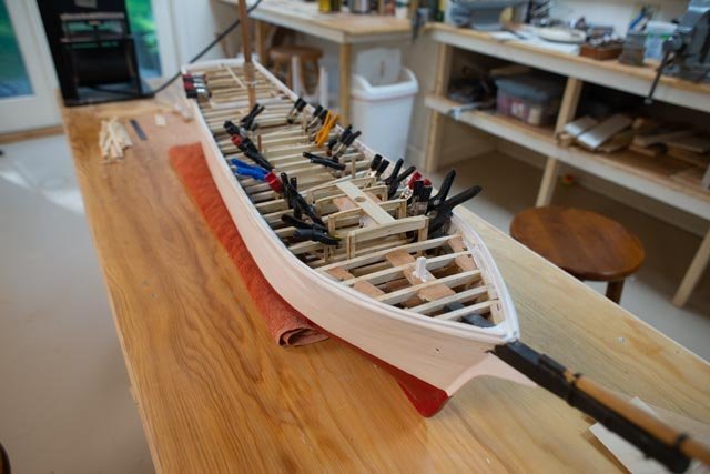
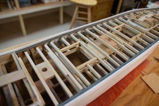
 here all the beams are in, the waterway is set, and first coat of paint on.
-
162
 this is a fun shot as it shows what should not be. Obviously, there is only one deck in this schooner. The lower main deck with its waterway and bulwarks is still there but not what I now believe is the right configuration for Ada Cliff
Production. making those little parts
During these projects that are several components to be prepared. Sometime we simple buy them like blocks and sometime we need to make them like turnbuckles and balustrades. Just to show that the work is now begun here are two views.
-
163
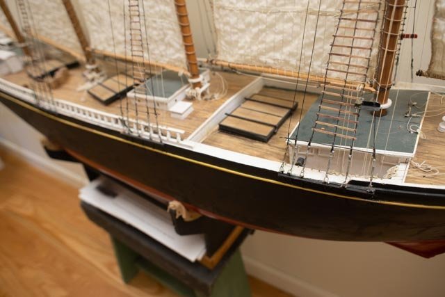 this view is from previous study and my build of the schooner Charles Notman. We see the balustrades come forward as far as the poop deck. On that schooner, it was very unusual as the poop deck came all the way forward past the main mast. Regardless, we see the difference of the main deck and raised deck. We also see the turnbuckles I made as part of that build.
-
164.
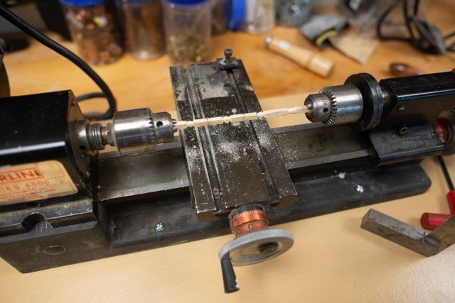 here I am using a similar technique as before to start making the balustrades. I am using maple this time to turn and shape them using files. We need about 100. So, a few each day is the way I try to work.
-
165.
 here is the first pile of blanks.
-
166
 here from my past build we see the main turnbuckles. I have found more photos and they all show about the same sizing. The main deck shrouds our held by roughly 5 maybe 6-foot turnbuckles. we need about 70.
-
167.
 here on the top mast, they were a bit smaller. I tried to make them 4 feet. [ Note Charlie was a sailing rc schooner thus the muslim sails]
-
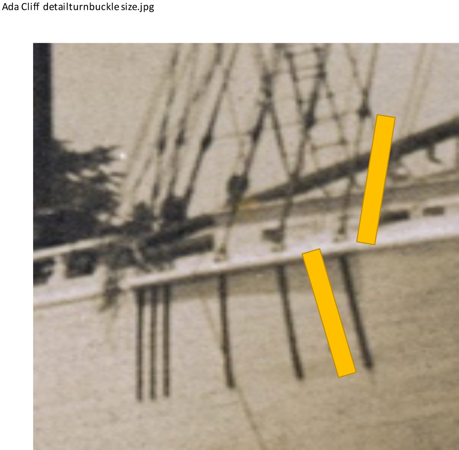
168
 looking at the launching photos of Ada Cliff, we see the turnbuckles and the chain plates are about the same size. I will go with 5.5 the compromise feet for both. Now I want to improve on the fabrication that I did before.
-
169
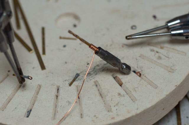
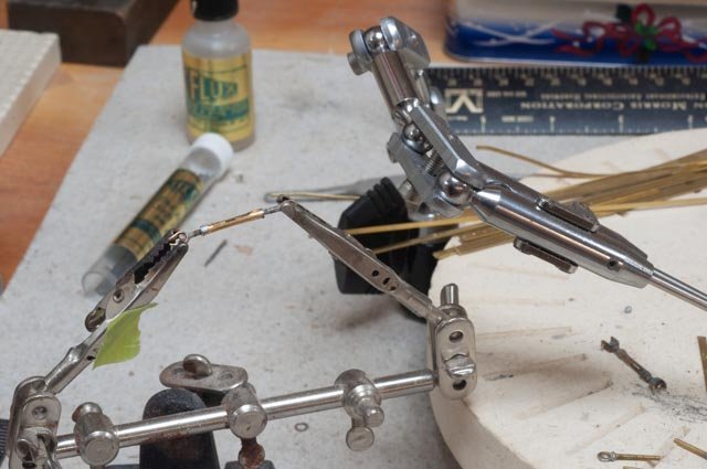
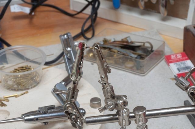 starting off I am where I was before. Here I am soldering the clevis. I am using a bent brass strip and a 0 hex head machine bolt. The steel shroud will be spliced to a pin in this clevis.
-
170
 I am doing here again what I did last time. This process does not get the look I want this time. I solder a small ring into the end of a screw top machine bolt, that I file to the best shape I can. I have since rejected this method and will show results next time.
-
171
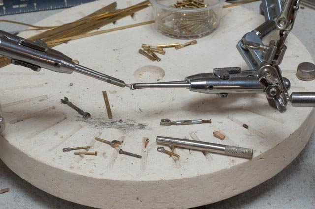
 here is the assembly of the unit. The two ends are stuck inside a small brass tube that has been filled to open the sides.
cheers
-
157.
-
Post 19
Masts are stepped, waterway is done and first painting to get ready for deck is started and then another oops!
Every once and a while a real brain cramp shows up… then again sometimes more research comes into play and we realize our earlier assumptions need to change. Let’s see what it was this time. The first issue is a minor brain cramp and it got fixed. The second one………Following the plans I continued to make some progress……..
-
144
 here we see the foremast is set through the cabin.
-
145
 here all three masts are set, and their tops have been adjusted to be the same height.
-
146.
 this shot is for the record. At least at this point the three masts lined up well. We’ll look again after all the rigging is done.
-
147.
 Here is an experiment. I have set the 8-inch seven king planks between the hatches. Next up I will need to sort out how to stain them.
So far so good?.... Absolutely not!.............Two issues have cropped up. One is an error in building cabins. It’s no big deal, but the other is an overall concern for the basic design of the deck level. As to the cabins, I made up templates for the sides. I got them all on, but things looked odd. Back to the books and sketches and recheck the height of these cabins…….oops
-
148
 remeasuring I found all the posts on the aft cabin are 3/16 "too high. That will not do
-
149.
 here they are cut
-
150
 here they are reglued
-
151.
 here are the templates on the fore cabin. It was not so bad. It was level and not following the shear line, so the aft post was high and the next two a little less. They were cut progressively to regain the right slope, parallel to the shear.
-
152
 here they are being reglued at the right height. Fortunately, all this cutting and gluing is under the cabins and out of sight.
Now for what I consider the big oops is for the deck construction. There are two opposing concepts in these big schooners.
• in one the main deck located at the shear line carries through the schooner. Then the poop deck and fore decks are raised above it. That is what the Priscilla Alden plans and the Bertha book show that I have been following
• in the other concept, there is only one deck level. Now that I have all these photos to study of multiple schooners, it seems that where the balustrade fly rail goes all the way forward to the fore cabin. That seems to happen because the deck is high throughout.-
153.
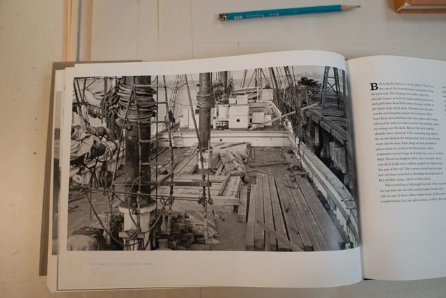
 this view is from the book Fly Rails and Flying Jibs . I have been going over more and more views. This view clearly shows the balustrade rail goes with the fully raised deck. There is no poop deck.
-
154
 this view is what I was building based on the drawings I was following. There is no balustrade fly rail along the length of the main deck
OOPS
-
155.
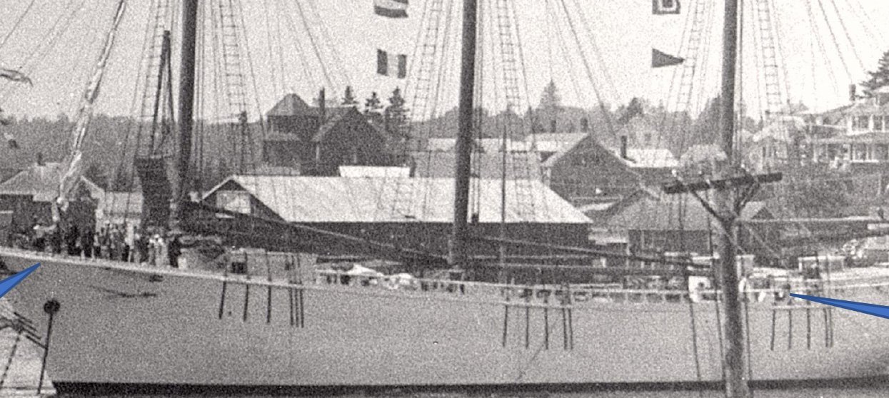
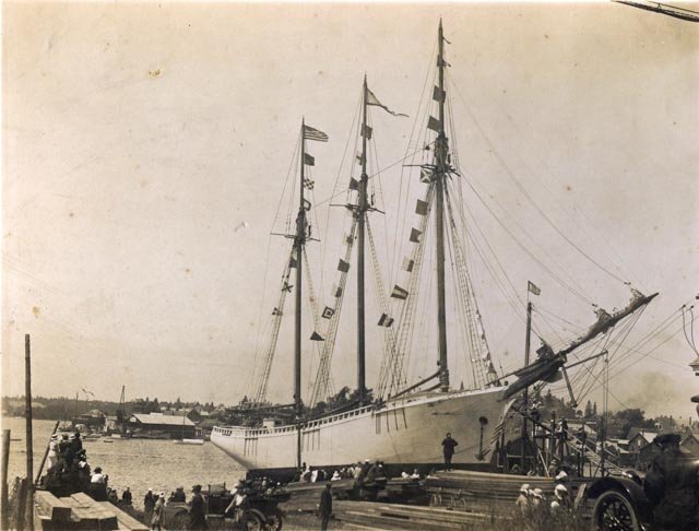
 here we are right after launch. The fly rails go all the way forward. One can see people leaning against the rail back at the main shrouds. Another detail that I understand now is that there is no indentation of thinner planks making up a bulwarks above the shear line of the main deck. I have been curious about that detail for some time, as the photos show continuous planks all the way up. Now it all makes sense. there must be only one deck level.
-
156.
 here is a broadside cropped picture taken after the launch.
My conclusion is that I need to fix this oops before moving ahead. If I use the photos of the schooner I am building, I believe I need to stop and fill in beams all the way to make one deck level. It makes no sense to continue as I am, because I would not then include the fly rail that is clearly in the photos.
Arge
-
144
-
Post 18
Research update and progress with underdeck
Now to share more of the research documents needed to avoid wild guessing.-
134.
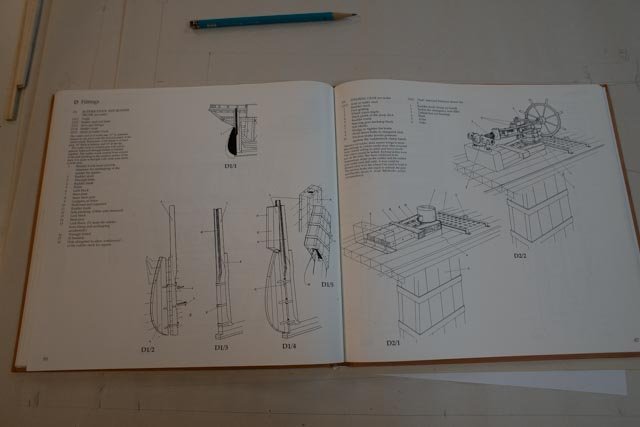 from the Bertha Downs book I used these two pages for the rudder assembly. The left page shows the total ‘cut in’ aspect of the pintle and gudgeons as mentioned earlier. The Right page, left image, shows the parts that are visible on deck under the gear box house, that I hope to replicate.
-
135.
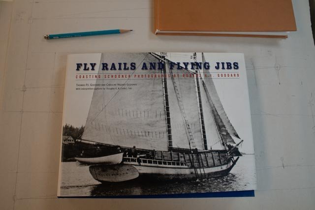 This is a new book. It is called Fly Rails and Flying Jibs. It is based on an incredible collection of photographs taken of schooners. It is helped tremendously by the writing of Douglas and Linda Lee. Douglas I am told is a Naval Architect who through the main Maritime Museum recreated drawings and details for Schooners including a four masted[ Charles Notman}, five masted {Cora Cressy} and the six masted Wyoming. These comprehensive plans and details are critical for anyone looking into these schooners. As a couple they also owned and sailed the windjammer Schooner Heritage for many years. The book is an incredible photographic resource specifically for new England Schooners. There are also many pages of photos and text all about Boothbay Harbor, the center of significant schooner activity. The Boston firm Crowell and Thurlow used the marine railway in Boothbay Harbor and the adjacent acquired land on McFarland point as the center for building many four masted schooners and subsequently providing the maintenance until their failure in the late 1930’s
-
136
 This view is typical of what can be seen for making decisions on what to show on the deck. This is especially true if one wants to model a schooner that was not just launched. The mast was clearly painted. I use this tone to compare with tones on the cap rail and pin rail below as I need to decide how to paint things.
-
137
 this is a similar view from another schooner. The main deck bulwark is what I am building, the simple poop deck enclosure. I love the little porthole.
-
138.
 here we are looking forward. The deck planking that the Bertha book told us to make 4 inches and it looks right on in this shot. It is darkish and dull. I need to do that in stain if I want the jointing to show through. This cap rail in this photo is lighter in color than others. It is more like a gray popular on fishing schooners. Another important detail is the turnbuckles. I made them previously on Charles Notman. I will use a clevis on the top and a ring on the bottom. I find that orientation interesting as using the previous info building Charles Notman they were the other way around with the clevis at the chain plate and the ring on the splice…we all live and learn
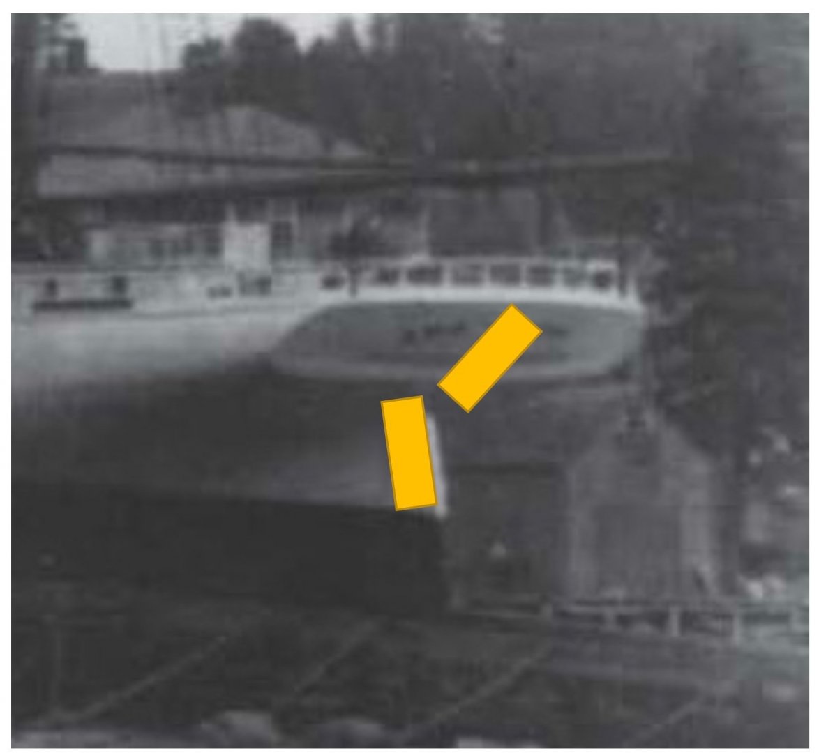
I share the next photo for fun. It is a mystery.
-
139.
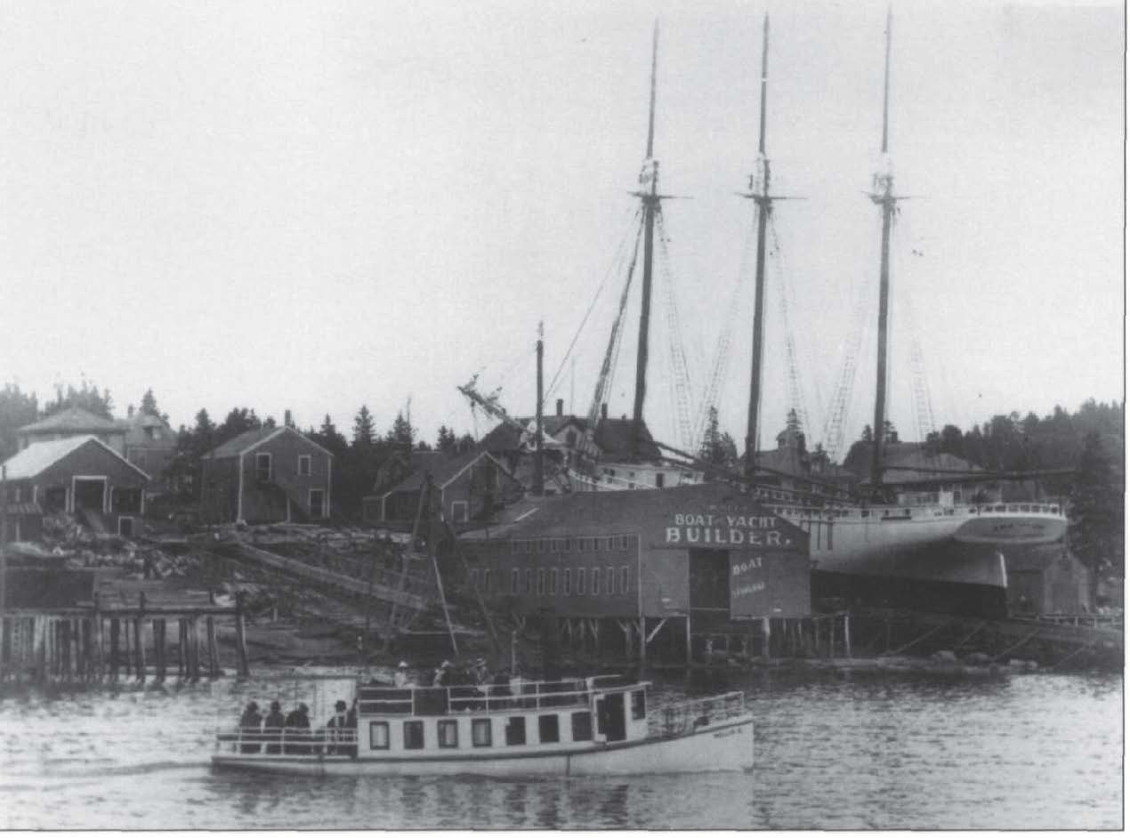
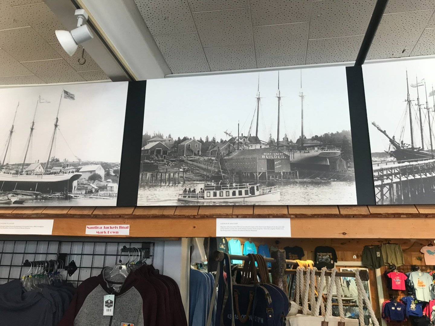 The original photo was included in Jim Hunt’s four serial articles in the Nautical Research Journal, on page 218 Vol 43 No. 4. Which was December 1998. It was credited with a file number from the Boothbay Region Historical Society (BRHS) but cannot be found at BRHS. I took this photo in the Windjammer Emporium Museum Store downtown where my 3 previous builds, all dioramas ,are displayed. It is a huge blow up that was done two years ago. There must be a digital file somewhere. It is important, because this is the photo that shows both Ada Cliff and the keel of the first four masted schooner, Marguerite M Wemyss.
One week later….
Well, a little luck and thanks to the owner of the museum store we have recovered it, and I have a nice high-resolution version to use. The Original I learned belongs to the Penobscot Marine Museum if one wants to acquire a copy.-
140.
 here is a cropped blow up showing the keel laid for the first four master based on the lines of Ada Cliff, the Marguerite M Wemyss. Ada’s Bow sprit is on the right side.
progress update
I continued to work on the fore ward cabin so I could step the mast-
141
 this view shows the dowel leading to the centering pin.
-
142
 shows continued progress with the chock rail.
-
143
 it is always fun to get that waterway on the transom. Now I have to think about all those turned balustrades.
All for now.
- bolin and GrandpaPhil
-
2
-
134.
-
Hamilton
I enjoyed reading through this log yesterday. I concur that cleanness and sharpness is wonderful. I am excited to hear your plans to go back to Bluenose. I followed your build closely when I was building my 1:24 Bluenose a few years ago. I still have a few detail on her that I hope to get to this fall and look forward to looking in on your work too.
cheers
Jon
-
Jim
thank you
I have enjoyed watching your work too. Ben Latham was one of my first models . I chuckle when I look at her now. The Dove is truly a fantastic project. I built a diorama of the first Hodgdon Pinky , built in 1816 a few winters ago and have drawings of another one built locally in 1834. I will share reference to it on your log one of these days. I have a few other projects before I get to that build.
jon
-
post 17
continued deck work and planningI continue a little each day with the steady production needed to get through all the preparation for the deck. Some folks put the deck on first and then try to paint around it. I like to think of it as a floor in a new room. Let’s get all the surrounds done and painted and then lay the deck.
-
128
 While progressing with the waterways, I am setting up to set the mast steps. I also am picking off whatever underdeck items I can like the cabins, quarter bitts and rudder. The hawse pipe holes are now in, and I need to run a little tube to carry the chain. so much to do.
-
129.
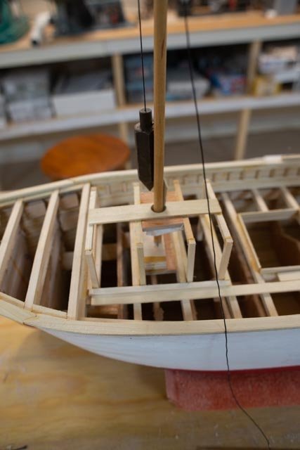
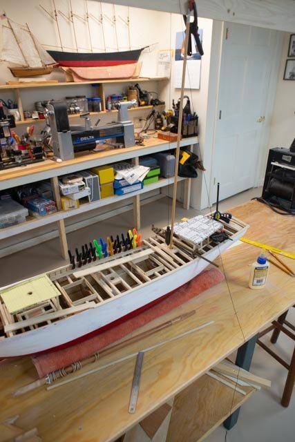
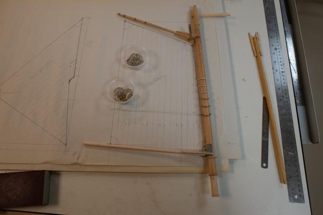
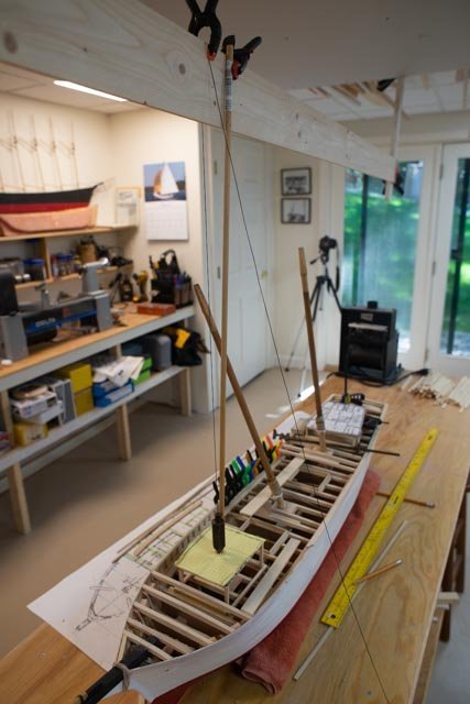 Here is my setup to set the rake and check the heights of the lower masts. The hung board over the model is set level. I can then measure both rakes and tops. The tops all need to be the same height and the setting of the deck level was a theoretical dimension. Let’s see how I did………I had to cut one ¾ inch and another ¼ inch…not bad
-
130.
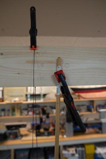 here we have the spanker marking on the board. From the Turbo cad I measure the rake to be just 2 inches at. 28 inches above the deck
-
131
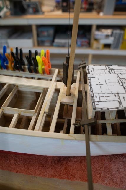 here on the deck, the dowel projects down to a plate where I mark for a centering hole [ the mast step].
-
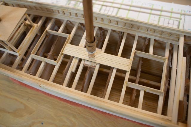
132
 As I progress forward with the waterways, I need to build up the roof of the forward cabin to receive the foremast. I have also have been infilling supports to catch the ends of the deck planking where it will run into the waterway.
-
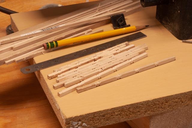
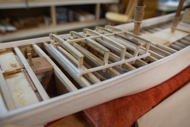
133
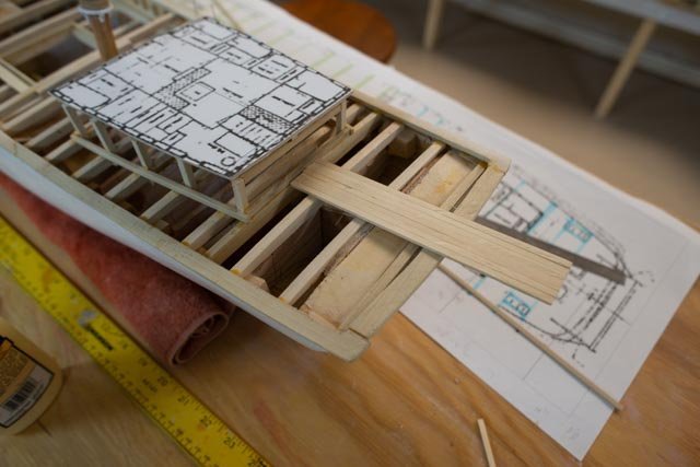 and just to balance out production I have started stripping the center 7 planks from the cedar stock pieces I milled earlier. These are to be 8 inches wide in scale, just under 3/16”. I will need to build in the quarter bitts and the rudder assembly as this work progresses before I set the planks.
All for now
- PRS and GrandpaPhil
-
2
-
128
-
Joe
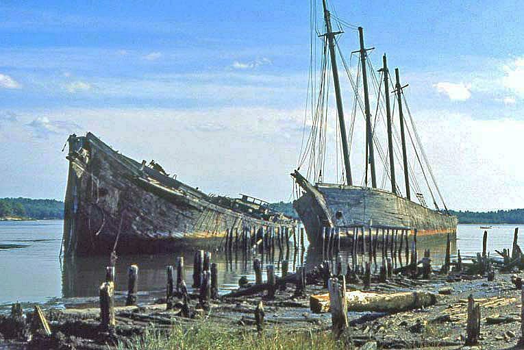
thanks again for sharing. Considering the time you must have survived the old Wiscasset bridge. It was not replaced until 1979. The two four masted schooners , Luther litter and the Hesper were beached there and the familiar landmark. They are also gone now. the photo came off the internet today.
I have been coming here all my life. My Parents retired to the same Damariscotta you mentioned. My family followed with summer homes and eventual was able to move to the harbor here in Boothbay where I always wanted to be. It is definitely special and a joy.
The main Maritime Museum in Bath is a fine beginning for a continuous maritime adventure if you get back to the mid coast.
jon
- GrandpaPhil and ccoyle
-
2
-
Joe
Thanks for sharing your fun experience near here. I have spent many hours over there on the next point watching breakers and even a few whales off the Pemaquid Lighthouse.
FYI there is a long story of how our town was renamed from Townsend to Boothbay. It occurred in that foreign state of Massachusetts. They were part of Maine back then. The town fathers wanted to incorporate and sent a crew off to the far away courthouse to register. When the crew came back the town had been given a new name of Boothbay. There is no definitive reason why. There was a family known as Beath who owned a lot of land. One guess is the court insisted on changing Townsend and asked for a major feature.That was the Bay. In the end they named the bay perhaps after the family, but no one could spell it.
anyway thanks for your kind words.
jon
-
Post 16
Deck frame and fix up shear line
I mentioned in an earlier post that I was not totally confident that I nailed the shear line while working upside down. Well, I found my prediction was right when I started checking things out. to get things closer to right, l did the following repairs.
-
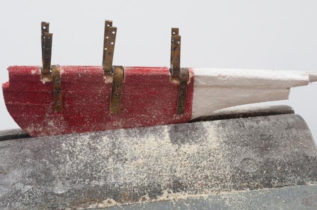
120 f.
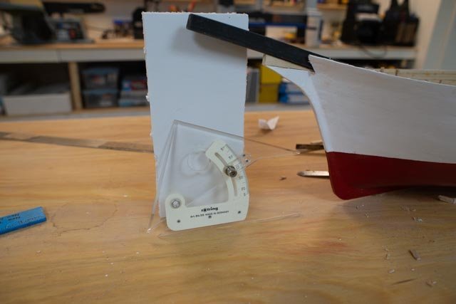 irst up was to compare the two schooner drawings and photos for the angle of the bowsprit. The consensus was 18 degrees. So here it is fixed with a shim. Filler and paint to follow.
-
121
 here I added a plank and tapered it aft. This added plank gets us to the top of the bowsprit.
-
122.
 I have talked a lot about the changes made to the stern to replicate the photos. Here a full plank was needed to make it all come together.
-
123
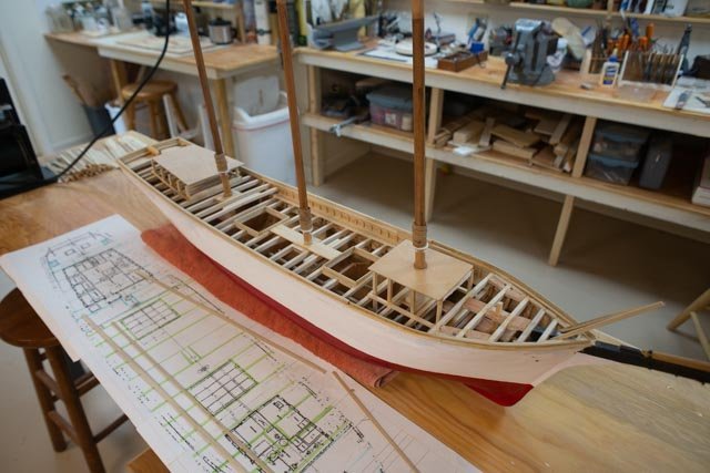
 Now we are in a long stage to build out the deck. I need to be sure the mast fits right etc. I scaled up the deck plan from priscilla to use as the basis.
-
124
 this photo show the bulwarks on the main deck. I will share the research that gave me the combination of continuous pin rails next time. I need to fit it, remove it to paint it dark and the bulkhead white before final installation.
-
125.
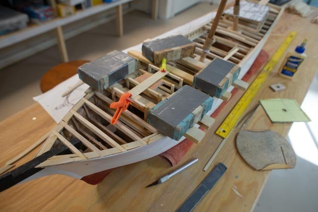
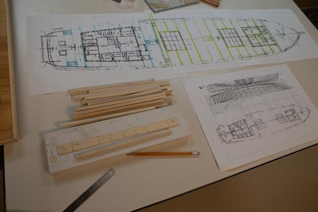
 Here is a progress update. The main deck beams are in, the framing for the deck houses and hatches started and the bow sprit in place. As I mentioned before I have milled up deck material from scrap Alaskan Cedar I had left over from a front porch project. It is laid out in 3/8” wide strips read for trimming down to the two plank widths I will use.
I wanted to share a detail I picked up from the Bertha book. It agrees as well with some photos I have, and I will get into next time. Most of the time we are used to soldering the little tube and pin on the outside of the gudgeon and pintle. Therefore, there is little cutting into the rudder, and it sits back a little from the stern post.
-
126
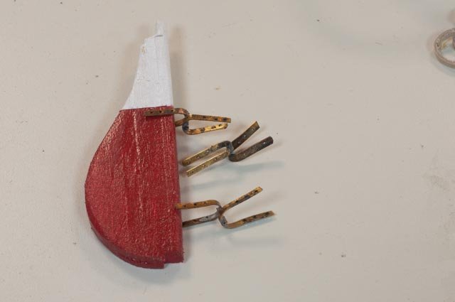 here I have followed the instruction for the large size rudder to replicate the band going on the outside of the assembly.
-
126.
 There is more undercutting of the rudder to make this work as the pintle is totally within the rudder. That approach tightens up the space between the rudder and the Stern post. The rudder and stern post must have some combined taper/ rounding to avoid binding.
all for now
-
120 f.
-
Post 15
Milestone we are off the building board!
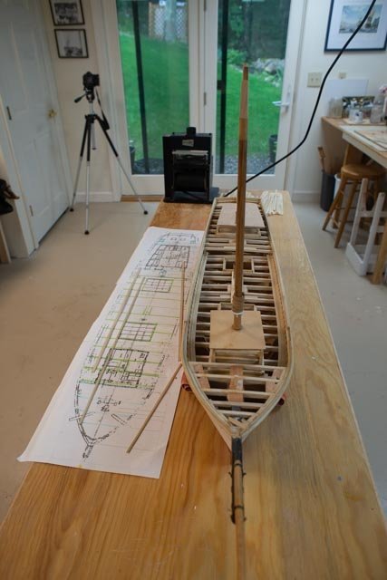
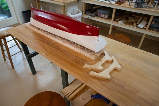
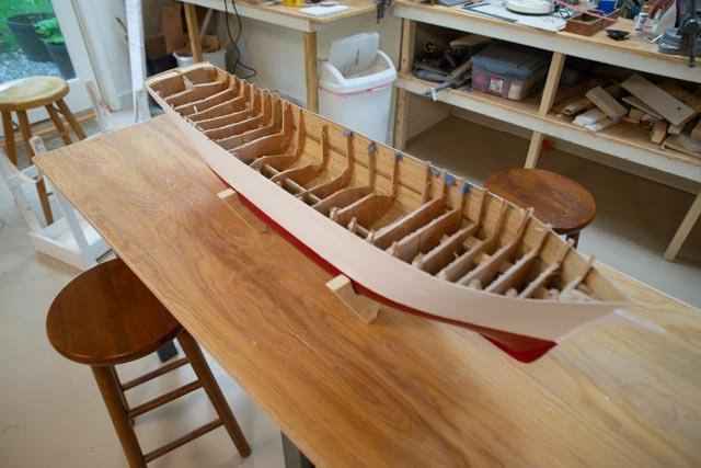
After numerous coats of paint, I have started getting ready for the next stage. That means figuring out the deck.-
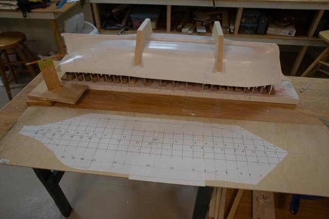
112.
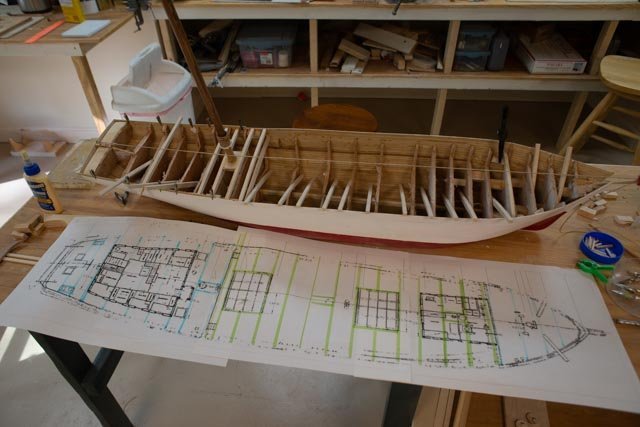
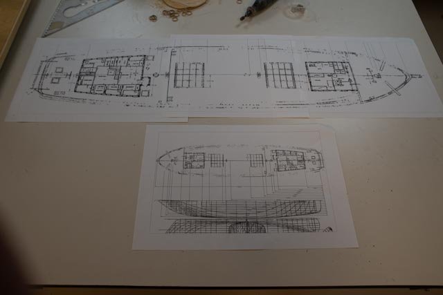 I have taken the plan from Pricilla Alden [ the only one I could find] and set it to the 149 foot scale. I then measured all the key elements to use as a starting point as I lay out the deck. Since Priscilla was built in the same town in the same year, I feel good about finding it. I have a few glimpses of the deck in photos that I will use when I get that far. The basic layout however was quite common. The large print out is to the model scale. At the full size I can use it as a background for layout when building the components.
-
113.
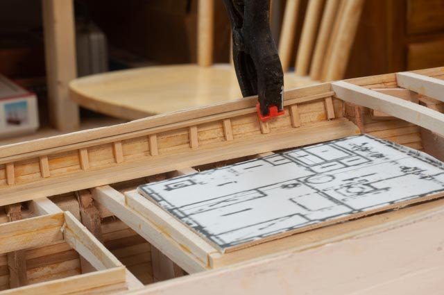
 first up are the deck beams. I have done this many ways and thought this time to make a jig and then shape all the beam tops for the right camber. Only 6 beams need to have the bottoms done as they may show if I decide to have loose hatches or where the deck is raised. The others I leave straight. According to the Bertha book, exposed hatch beams were 14-inch, so that was the goal. Just over ¼“ deep. All beams are ¼ “wide as that gives the best support for the decking. I am putting in enough beams to build the model and not researching to have every beam and all the different sizes as I did when doing plank of frame on my last Schooner.
-
114.
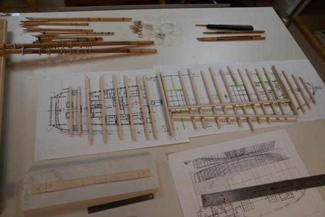 here I have made up all the deck beam material I will need so I can go quickly when the time comes. Next I will study how and where to build the clamps .
-
115
 I have made more progress on the spars. My goal was to work parallel, so when the time comes, they are ready.
-
116
 here I have sorted out the different coloring I am using for my attempt to replicate the masts.
Now a drum roll. I have decided to stop painting the hull and move on. I obviously will do some damage and touch will be necessary, but I feel I did enough for now.
-
117.
 here we are with tape off and the waterline touched up. I have purposefully kept everything in a gloss for now. Most models are displayed in low light and for now I like the highlights. I can always tone it down if I change my mind.
-
118.
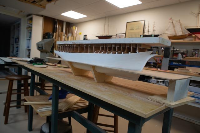
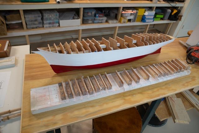 and Ta dah! The building board is gone……
-
119.
 and here the rough-cut removal of the bracing that interfere with the build. There is a lot more detail work as I lay out the clamps for the deck beams. This first cut was with a utility tool. It was crazy to use but efficient. I only put one small hole through the planking for my first touch up.
All for now
-
112.
-
Post 14
I am going to paint the hull!
There are maybe 10 coats of brushed on and sanded gloss white acrylic. One issue is that white paint is slow at covering red glazing putty. I am using up the gloss as it shows defects more clearly. I think I am done with that stage, the priming, I may want to go with a satin finish and few more thin coats. I am trying to end with a smooth brushed on method and save the airbrush for next winter when I have time to learn how to use it.
-
104
 here is the hull at this stage. The light pencil dashes show where the waterline will be located using the Bath built model information. Checking against the photo 77 above I was happy where it is on the side. I was not yet comfortable overall especially at the bow and stern.
I did a little more checking in the bow and stern area. I went back to the Historical society and got a few more photos that helped with the following review. [ low tech as it may be]
-
105
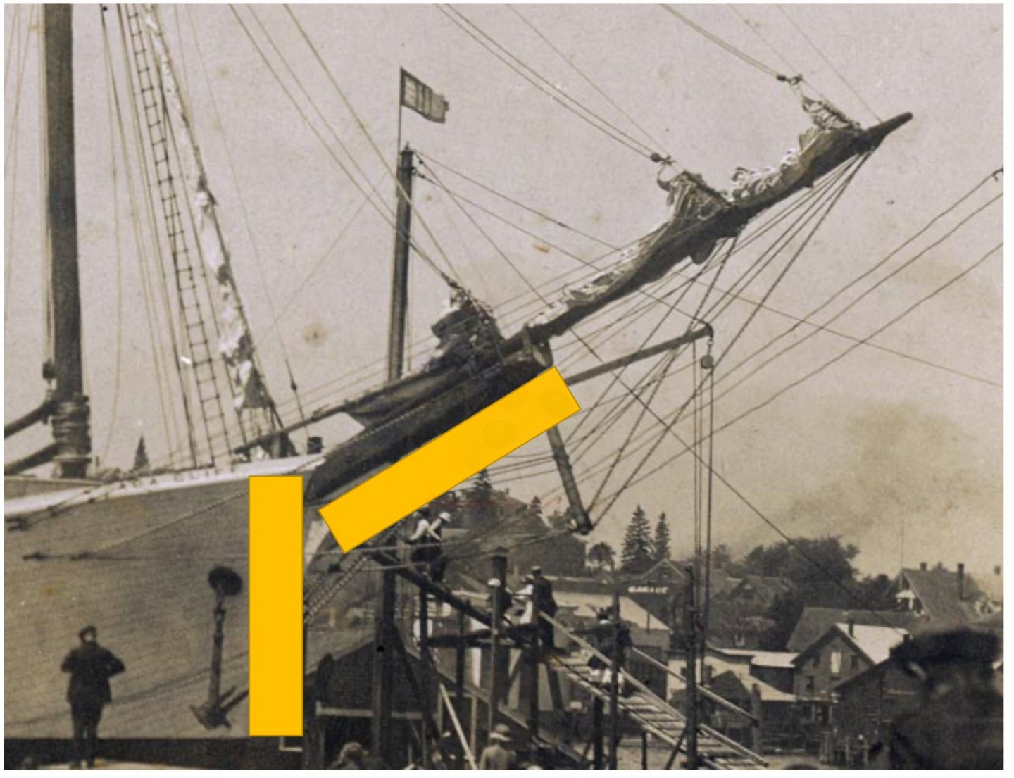 I placed the bow photo in excel and made a simple rectangle that measured the exposed bowsprit. That is also a known dimension from the rigging plan after scaling. The second copied rectangle is located to show that the distance down to the waterline is the same, roughly 4 inches or 16 feet. That makes the anchor about 9 feet.
-
106
 does the same thing at the stern. The result was to lower the waterline about 2 feet [ ½ inch in scale].
Now it is time to play again. I will soon be cutting the hull off the building board. What type of stand makes sense? I love the models that use acrylic or other media to replicate the sea. That gives us a view of the schooner above and below water. In Bowdoin I used colored bubble Acrylic, I let the viewer see the sea bottom too. I will start with that option available. I can always abandon it later if it become unwieldy.
-
107.
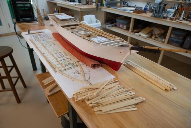
 here are two cradles made from Station 9 and 15. On the table is a new print out of the plan view. I went through in cad and measured every station at the waterline to give me a point to start cutting out the Luan Plywood.
-
108
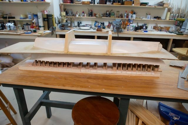 here after several hours we have the water surface as depicted by Luan plywood. The cradles could become supports for the water surface as well.
-
109
 here for review I have turned all right-side up and share the look I love to make. The bottom is clear under the water level and the hull proportions are much more pleasing to my eye by being only above the water. If I change to acrylic, it is even better. I then must consider the size and how big the display might become. I also fear the cost of the acrylic. It was hard to find for Bowdoin and $$$
-
110
 the possible bow shot
-
111.
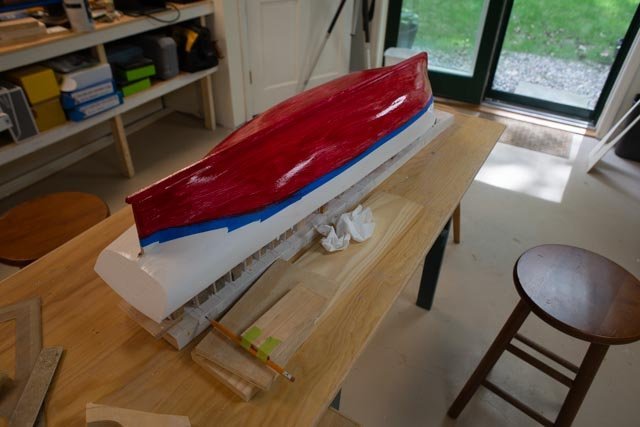 here we go with the first of probably several coats of bottom paint. I am still a low-tech guy that paints and sands and paints and sands and paints eventually gets to a surface I can live with.
All for now
-
104
-
Allan
good to see you dropping in. I have been away a bit sailing and doing that wonderful summer thing. I was off to the Historical Society last week and found some more images. I also couldn't find some I know they have, so more to do on that one in the fall.
I agree the research is much of the fun. Also staying with the theme of Shipbuilding in our harbor lets me find more and more cross referencing.
it's all good. even if I build an ugly Schooner, I will gain a great library. I just ordered the book you recommended for the sail making. I 'll update after I read it
'
thanks again
jon
-
Thanks Allan
ordered the book today and will look at the video
cheers
- thibaultron, mtaylor and druxey
-
3
-
Allan
after seeing your Boothbay Schooner I am game to trying this method out. I am look now for more tutorials
cheers
jon
- thibaultron, mtaylor and druxey
-
3
-
Post 13
Closer to painting the hull and more work on spars
I had to laugh at myself as I reviewed photos in the log and found I mislabeled one as the Ada Cliff; that was wrong. I have several photos in the archive, and I pulled the wrong one apparently mislabeled a few years ago. The substitution does not change, but reinforce my conclusion, I just thought I should set the record straight. I also edited the earlier posts identifying the other Schooner.-
95
 here is the photo for which I need to get a larger scan to allow blow ups for more details. It shows the white transom on Ada Cliff. The larger size and closeness to the 45-degree slant agree with both Priscilla Alden and Lillian Woodruff. All is good.
The waterline painting and spar finishing
One bonus to the above photo is that in the lower left, one can see the keel for the first four masted Schooner has been started. The yard alternated building one after the other for the following few years.
Back to painting the waterline, I see here in the photo that the sharp rise in the transom may be more of an angle than I achieved using, and then then modifying, the Bath built Schooner drawing. In my preliminary check, the waterline will not be quite so low on the rudder. That would suggest that despite my efforts the shear of the transom does not yet swoop upward. I hope to be forgiven once again if that pans out.
The following image and blow ups are from the launch day newspaper photos, now available at the Boothbay Region Historical Society. They will be the basis of my attempt to make this all work out to be representative of the actual Schooner.-
96
 this view is the overall shot. After I lay out the waterline, I need to determine if another bulwark plank may be needed to get the rise in shear at the stern. I hope not, but only time will tell and only the few readers of the log will know….smile
-
97
 In this blow up we get a sense of dark and light for treatment of spars. The mast in the hoop area is darker that other photos. The Boom Saddles are clearly white, but the yokes are natural. The hoops are a lighter color; perhaps they’re ash or white oak strips.
-
98
 This view shows all the bow sprit and its rigging and trim. Also, the anchor shape and size are clear. This view at this point will help me identify the right waterline. It is clearly a big drop or better se=aid the bow shear looks high.
-
99
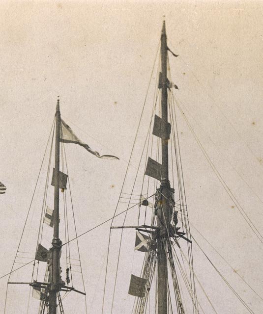 here are the fore and main top masts. All of the spars seem to have remained natural. The cross-ties look to be dark. As they as typically made of oak, I assume this work was all painted black. The iron work is clearly black, not galvanized.
-
100
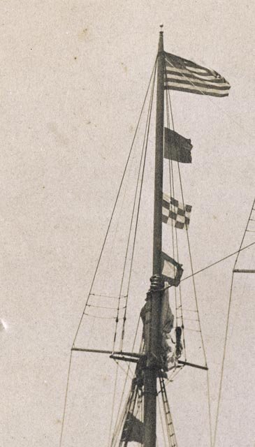 here is the Mizzen top. It gives a clear view of the rigging and will be helpful at that stage. Now it just confirms the dark finish.
With these photos not at high resolution I still believe I can move forward finishing the spars and finishing and iron work. Before I get into the rigging process, I hope to get higher resolution photos and pick some more detail
Back to work
-
101
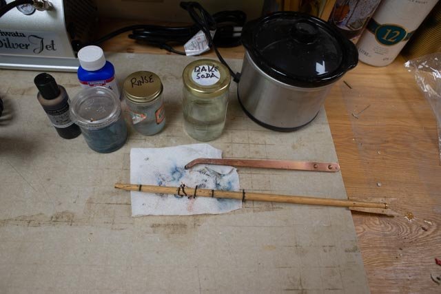 here I am setting up the two types of blackening I am trying to perfect. I am using the kettle with Sparex for pickling and Brass Black for brass and Liver of Sulphur for copper. The first fittings are on the spanker boom. I am leaving them loose until the mast is stepped and I line up the sheet band. I dare not fix it in now.
-
102
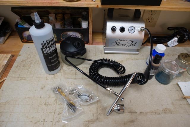 here is the brand new, never used spray paint set up my son recommend for the amateur that I will be. I need to break in to avoid the issue of brush strokes with acrylic paint.
-
103
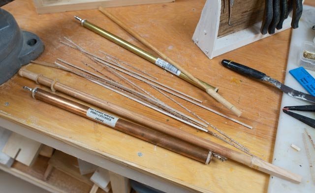
 here is an update photo of the spar building program. I keep working on the different areas. I need to get the lower masts finish right and then the hoops on. Once that is done, we begin the crosstree building. In the meantime, there is a lot of brass and copper iron work to do. I have sanded the hoops to where they still have some strength. At some point I need to stop and go forward. I still need to look into getting some veneer that is flexible enough and stable enough and then find how to cut narrow strips. The birch works ok but a paper think it slides under the saw fence. May If I keep scanning logs in the how to do I will find on on making better hoops using wood.
All for now
-
95
-
Post 12
Think about hull painting and progress on spars
First up was our monthly Guild meeting in bath, City of ships.-
84
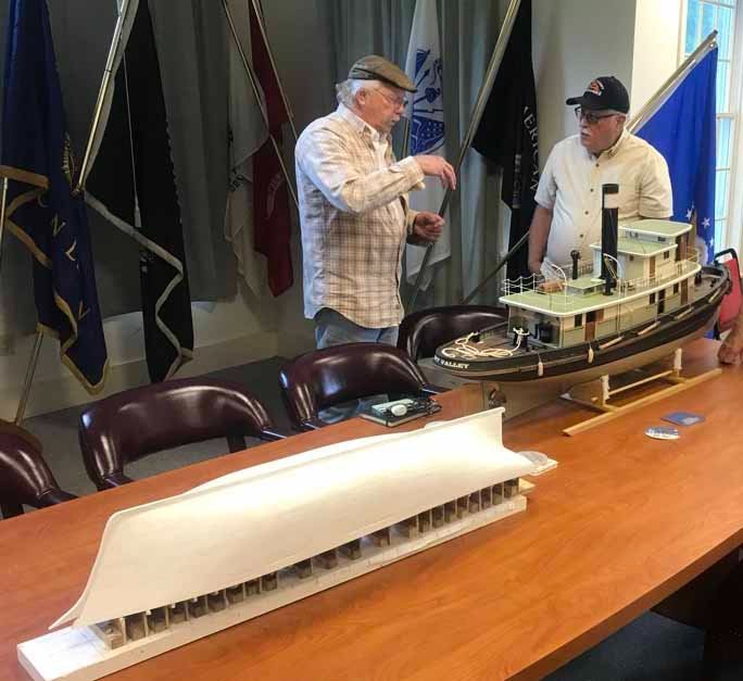 the tug sitting next to the Ada Cliff hull is awesome. The detail amazing and yes it will motor around a pond this summer. Thus another discussion of whether to sail Ada Cliff.
The group was kinder to me since I fixed the incorrect stern as reported last month. They thought my idea of scratching little lines on the planks was nuts, as they would never be seen under paint. One thought the planking on fast built coal schooners of 1917might not have been too perfect, so why take out all of the dents anyway. It shows there are many choices out there when deciding when to paint and more forward.
As a follow up, my son visited and convinced me to buy my first airbrush. It comes in a few weeks, and I will obviously need to practice some before using it. Therefore…-
85
 here I am going over dents and things with more glazing putty and sanding vigorously after each coat of paint. The hull is resting though with so many visitors as well I am therefore going ahead with the prework on spars and planning for sails
How to rig a large scale schooner….could it sail?
The milestone reached by completing the planking means many things need to be decided. I want to share a photo from my 2015 model of Charles Notman. It was a similar 1:48 scale Maine schooner. The big difference is I definitely built it to be an RC sailing schooner. Let’s look at some of the decisions made to support that approach and see what I need to do now. I do not plan to sail this model.-
86
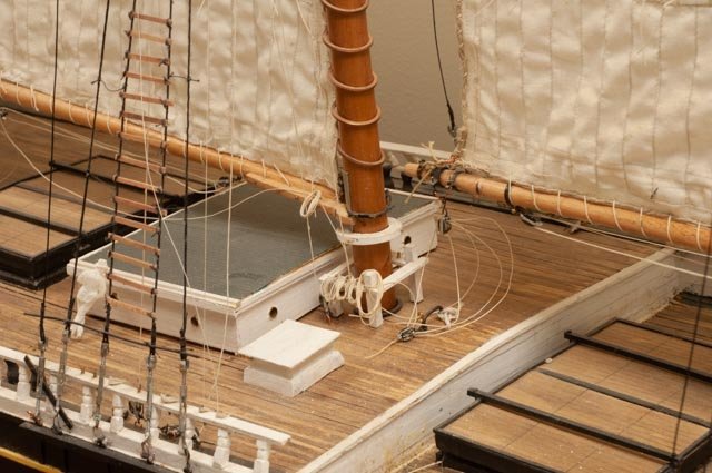 Charles Notman model foremast details. There are many things to look at here and then decide if they are appropriate. Also, as all of us learn from our mistakes what improvements can I make 6 years later.
1. Mast coloring and hoops. As this was a RC model, I chose thin 1.5MM brass hoops. They aged nicely and since it is a sailing model maybe OK.
2. The mast is Sitka Spruce stained dark. it should have been dark only in the area of the hoops as the mast was greased there. Having sailed on Bluenose II and seen many Maine Windjammers the mast is its natural color away from the greased areas. Some are painted from the boom saddle down and cross ties up.
3. Sails were sewn muslin. There is lots of info advising anyone at this scale not to use cloth or sewing machines etc. Since “Charlie” was a sailor, I still feel that gives it a pass. I will not use cloth. I hope to learn how to work with Silkspan on this go around.
4. Turnbuckles. I used brass tubes filed to make yokes and small machine bolts for the ends. Obviously, half of the threads are not left handed, and they do not work. They were painted Aluminum paint to give the galvanized look. What I plan to do will be similar, I just hope a little better soldering etc.
5. Balustrades. One hundred plus and I turned them with files on a small lathe. I assume the same and again just hope for a better consistency. I have also become a little more selective in woods.
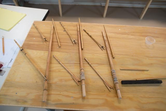
So, let’s get started with the rigging plan for a static model. I still hope to get the running rigging right and that is a key interest I have. We need to be able to keep the understanding of how these big elephant-like rigs worked with such a small crew.-
87
 first up is the boom saddle. I usually sin again and make these out of plywood. Drill the center hole and then sand the outside of the doughnut.
-
88
 here I show what I am not going to do. I struggled to find more of the 1.5 mm smash rings and came up with these. They are thicker! Great for out of scale RC sailor. They are going into storage.
-
89.
 here is the start of what I hope works out. I use 1/64 birch ply and cut strips. I find the saw strips the bottom layer, so with that I dare not cut any narrower. I will need to sand them down and I am not sure how narrow it will come out.
-
90
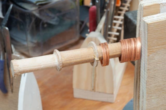
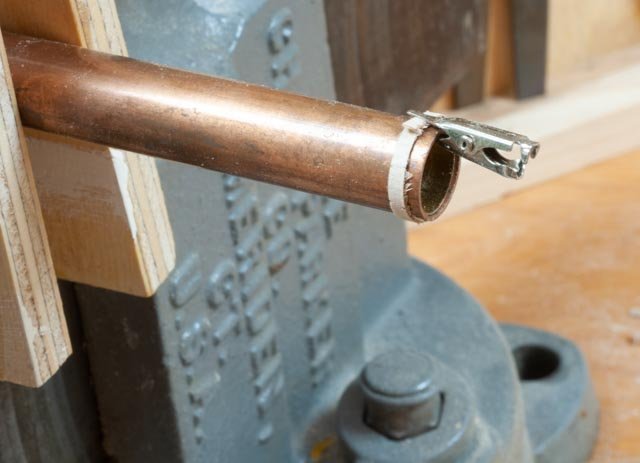
 here I have selected two sizes of tube to use for the hoops. This schooner used them on the uppers as well.
-
91
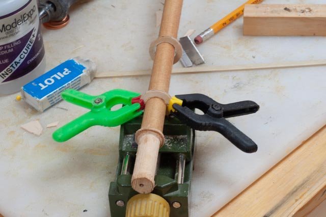
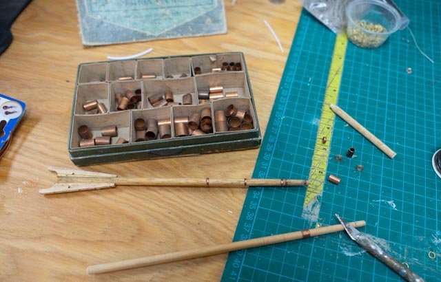 now for all those little bands. I learned this trick from a clipper ship log last year and it works. This little box contains what I am told dentists used years ago for making inlay molds. There are 14 diameters of thin copper tube. One is on the tapered dowel by the X-Acto knife, I cut the bands by rolling it. The bands then find a nice snug fit. Occasionally for the smaller end we need to cheat and add a dab of glue. Once the annealed steel wire eye goes through the spar, all is secure.
-
92
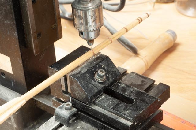 here I am drilling through for the peak halyard hardware for the wire eyes.
-
93
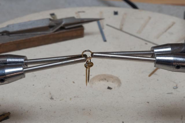 here I am soldering the little rings to make up the linked hardware for the throat halyard
-
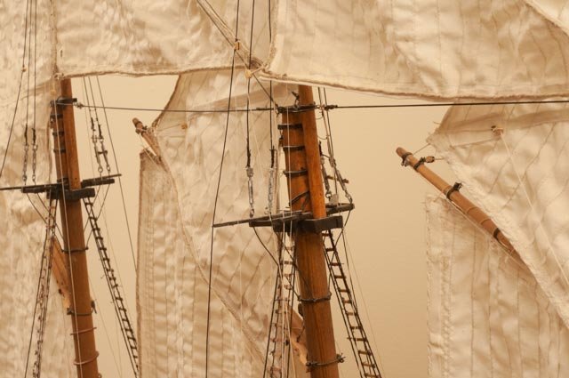
94
 here we have a progress look as we work our way through the foresail spars. For look only I put three of the old brass smash rings like Charles Notman and then three partially sanded hoops. Considering that the hoops will not be bunched below the lowered gaff, but sewn to the sail, I believe they can be a little bigger than reality would dictate. I hope so anyway.
All for now
-
84
-
Thanks Tom
it is always fun to get those last few planks installed
now the issue to ever get satisfied with sand and clean up to go ahead and paint.
cheers


ADA CLIFF 1918 by Jond - 1:48 - three-masted Boothbay Schooner
in - Build logs for subjects built 1901 - Present Day
Posted
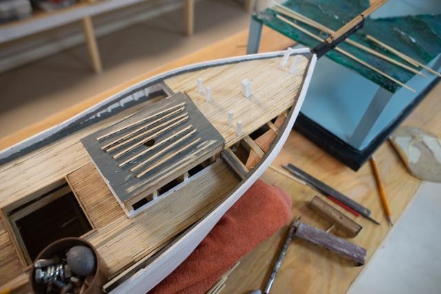
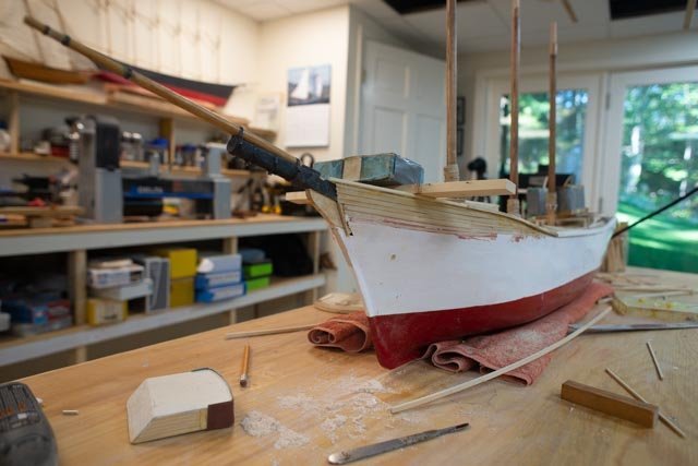
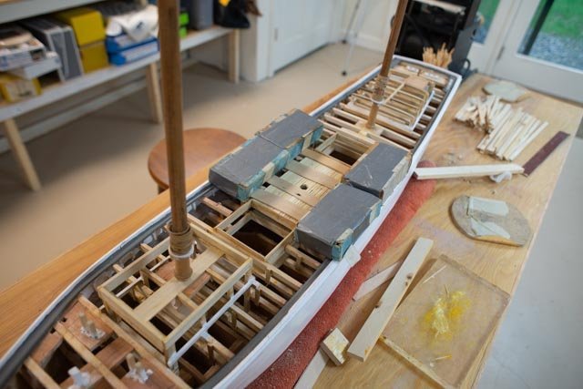
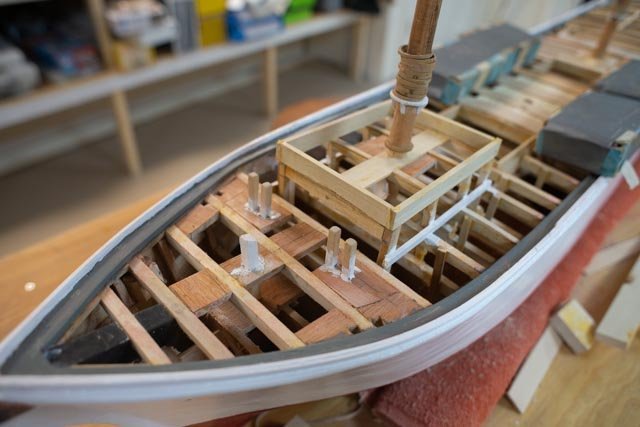
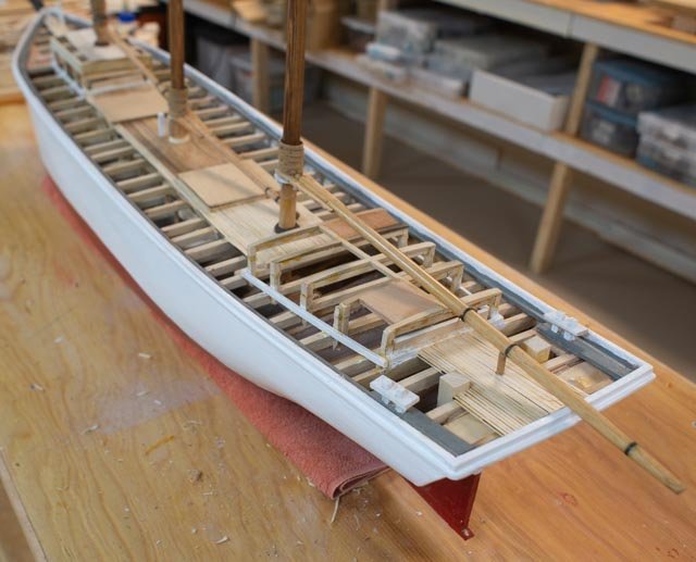
Post 26
Stain the deck and begin deck furnishing
Staining and finishing one’s deck is both a personal and historical effort. I rationalize that with some exceptions we only have black and white images, so when a nice warm cherry blend is added, it is OK. Another issue is making the rear admiral happy if the finished model is to stay home. In the first shot, I was experimenting a month ago with the dull brown of walnut stain on the Alaskan cedar. It was not approved for the home showing and warmth was required.
Starting the deck furnishing:
There will be many different topics here as we all know. I tend to work on a little of each as I go. That means my updates will have a little of each and not be by subject.
All for now