


barkeater
-
Posts
320 -
Joined
-
Last visited
Content Type
Profiles
Forums
Gallery
Events
Posts posted by barkeater
-
-
Dave,
Hopefully those brass rings look like eye bolts otherwise you are going to have problems😁. You are correct, superglue (cyanoacrylate) is what you want to use gluing metal. As to breakage, I've never had a problem with kit supplied rings/ eye bolts. They may bend but unless you really use a lot of force, I can't see them breaking. For scratch building I use silver wire which is stronger than craft wire.
Richard
- Keith Black and mtaylor
-
 2
2
-
Bill
The picture of the stock sheet you show is a pretty standard top which you should be able to copy. There are a lot of books on rigging if you can't find what you want for free by search. Rigging: Period Ship Models by Lennarth Petersson shows a similar top and is on Amazon in a kindle version for $11.99 ($36.70 for hardcover). There are a lot of books on rigging so look around, but I believe you could use this one to make the top you show, and it is relatively cheap. It is also a good book for other rigging details in a general fashion but does not go into changes in masting and rigging over time as some of the more voluminous and scholarly works do. Again, look around and see what you feel would be most helpful to you.
Richard
-
Welcome to MSW and enjoy. I'm a little quicker on building models but not much as I'm coming up on 4 years on my current build with years to go.
- Ryland Craze, JeffT, JimmyK and 3 others
-
6
-
-
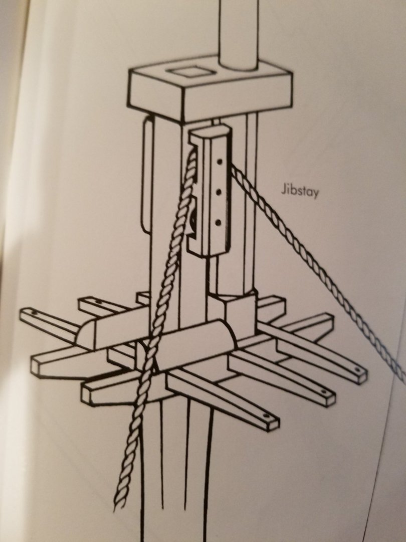
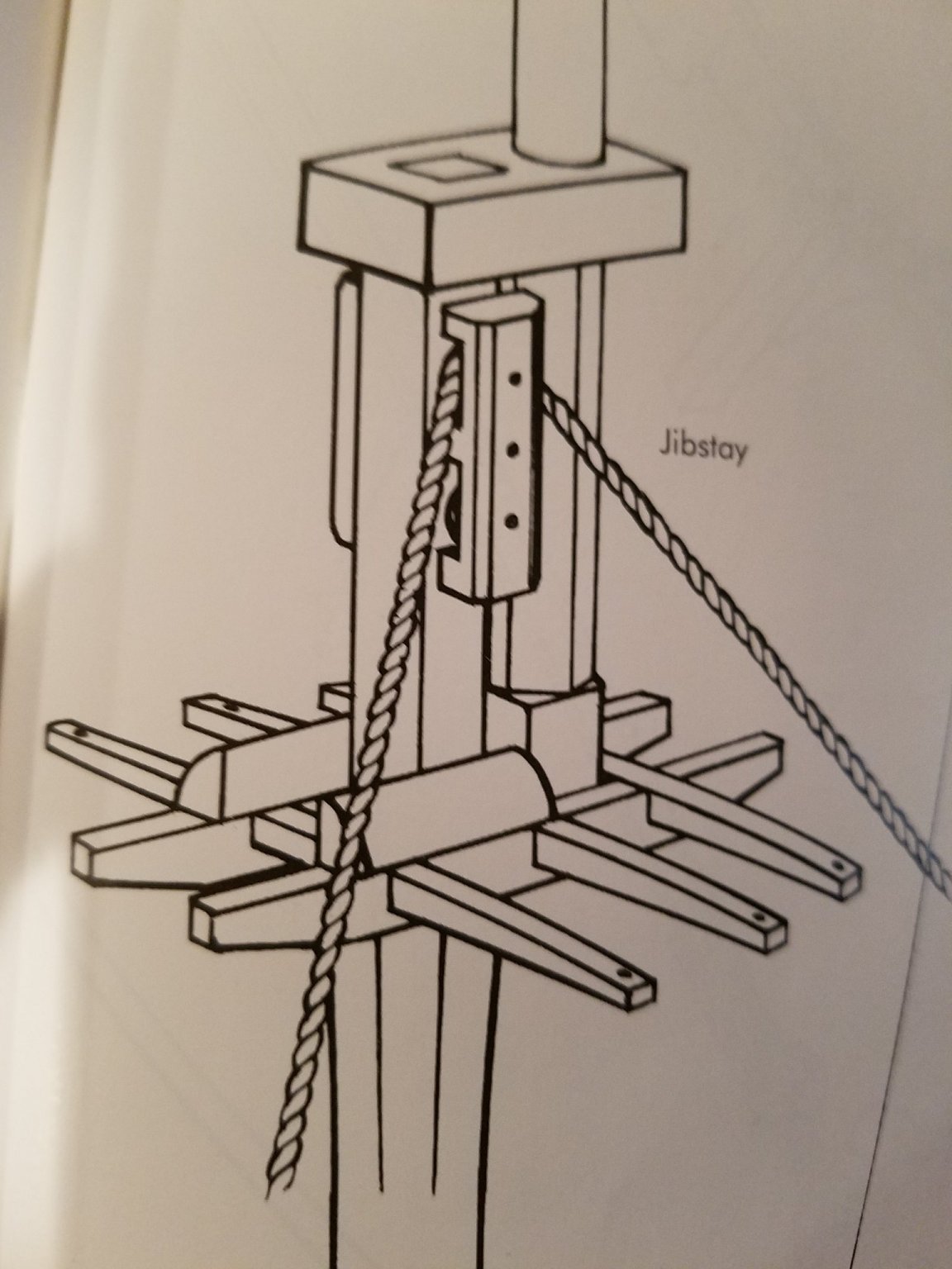
Tommy,
As Mark noted masts are quite a wide topic and different masts and yards show different shapes. They also changed over time. If your question is in regard to mast caps, the following illustration from Petersson's "Rigging Period Ship Models" may be helpful. Here the main mast is squared off to sit into the mast cap. The top mast is first square to sit on the trestle tree, then becomes octagonal before being rounded off to fit through the mast cap.
Richard
- Tommy Vercetti and mtaylor
-
2
-
Painting them black would give you more contrast and help them stand out. Just a thought.
Richard
-
I use 5x glasses. I paid about $10 on Amazon. I like these compared to magnifying lamps because I can change my field of view without having to move the lamp.
Richard
- Canute, Ryland Craze, mtaylor and 1 other
-
4
-
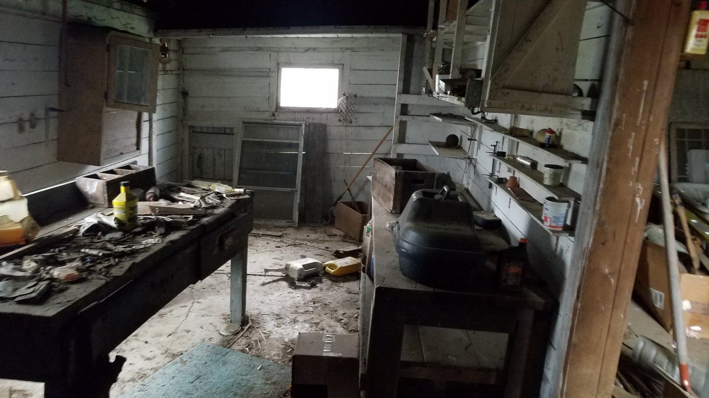
Cisco,
What I did was tear down and replace a shed which was attached to my barn. The barn from around 1860 is in good shape with wooden pegged construction including main beams up to 39 inches. The shed was a later add on probably 1940's and was poorly done and had no footings or foundation being built directly on the dirt. It was a tear down so I used the footprint to design the new shed with the help of an architect. I did have to get permits but by using the existing footprint there really could be no objection as long as I built to code which we did. As to lighting, you will want more than natural light as discussed above. Good luck on you workshop project.
Richard
- Canute, Rik Thistle, CiscoH and 1 other
-
4
-
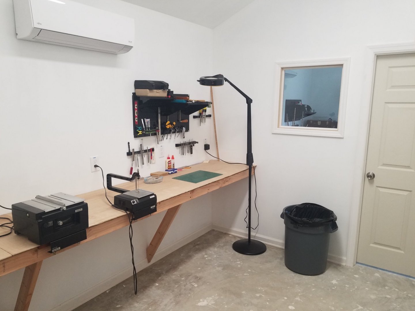
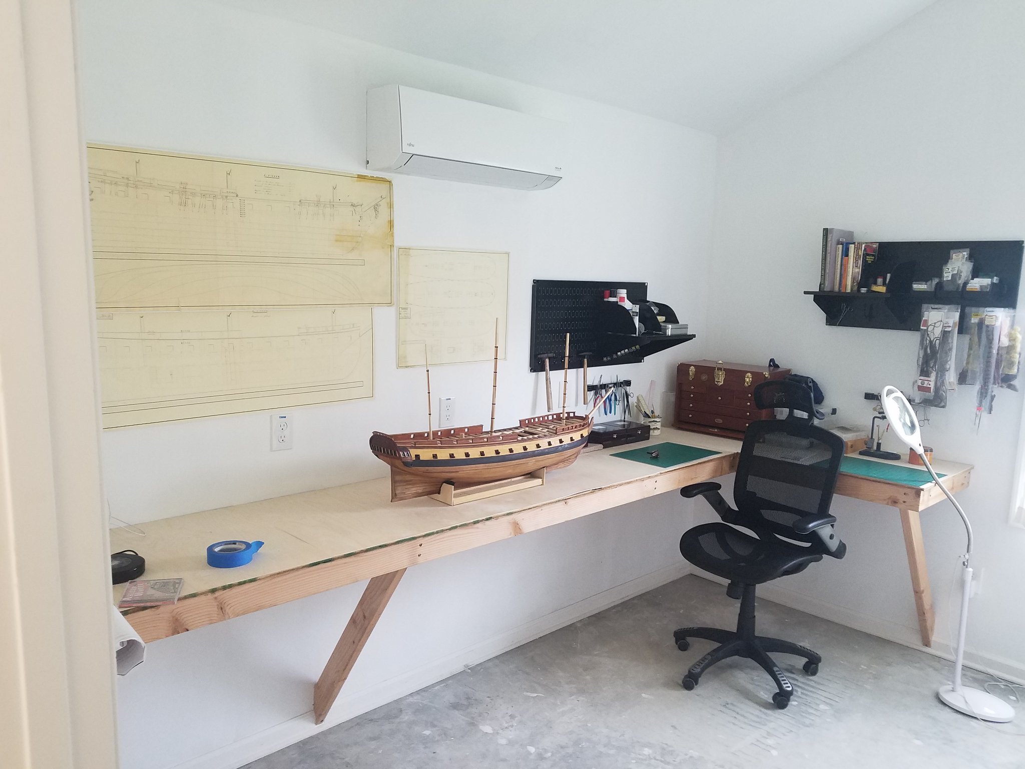
Thanks for the tips. Not in the pictures are high output 4 foot shop lights in the ceiling of both rooms. In the last picture note the brightness. There is no window in this room to the outside with the only window being into the other room which itself has only one window. Without the light on, this room is very dark. I kept the windows to a minimum to give me the most bench/wall space. I moved the two floor lights from the house to get them out of the house but so far have not needed them for modelling but have used the one next to the window when tying flies as I tie a lot of micro flies. I also wear 5x glasses both tying and working on my model. As for pedal controls, I had a Fordom with foot pedal whose motor gave out after long time use. I used to carve decoys with it but don't see any use for it with the way I make models. I do have a Dremmel and a Craftsman rotary tool without foot pedal but use them infrequently. I do have a fold down bracket but use it to hang my waders. My shop vac in the sawing room is not in the picture. Since the other room is set up as a clean room where any dust creation is to be kept to a minimum I can't see cutting a hole in the wall. I do need to look into a dust trap for my sawing.
Richard
-
-
Might I also suggest for your reading list Bloody Mohawk by Richard Berlith which covers the Mohawk Valley and the NY frontier from before the French and Indian War through the Revolutionary War and The British are Coming by Rick Atkinson the first of a trilogy. I'm still awaiting the second installment.
Richard
- Keith Black and mtaylor
-
2
-
Welcome to MSW. I grew up in upstate NY (Gloversville). Thank you for your service. Since you are in Saratoga, the Philadelphia from the battle of Valcour Island may be of interest,
Richard
- Ryland Craze, Keith Black and mtaylor
-
3
-
Welcome. As Chris said, a great way to start would be to search" first finished builds". Also if you l look there are threads under ship model kits which would be helpful and there are discussions on which company puts out the best products including instructions.
- Keith Black and mtaylor
-
2
-
-
After years of building with equipment all over the house which I had to drag out and then store again, I now have a dedicated shop. Yippee! I replaced the original structure which was a shed attached to my barn with the new structure which has heat and air conditioning as well as exhaust fans. I split it into two rooms one of which is for sawing, filing and anything which creates dust. The other room is for metal work and assembly. I also included a fly tying table as I am an avid fly fisherman. I still have plenty of room left over to add tools. I'm thinking of a thickness sander but I don't need it yet.
Richard

- Rik Thistle, usedtosail, CiscoH and 26 others
-
25
-
 3
3
-
 1
1
-
It is tough to tell from the picture if you have enough info. I do see sheer lines which should make constructing the hull possible using bulkheads and this would be another option other than a solid hull. First decide your scale. If you are not going to use the scale given which I believe is 1/96 by my math then figure out the correction needed (say 200% enlargement if you go 1/48). Have the plans enlarged and copied which can be done at an office supply store. Now start making copies on your home printer. Cut out each individual sheer line remembering to subtract for the thickness of the plank(s) you are going to use as sheer lines are from the outside of the hull. Since sheer lines are half hull you will need to make these into full hull by matching two 1/2 copies and the make a full width copy with your printer. Glue these to plywood and cut out your bulkheads. Their positions on the keel I believe are given but it is tough to see in the picture. From the looks of it you are going to have to add additional bulkheads in between to allow a smooth flow of your planks. To do this make additional bulkheads using the broader of the two where they are going to sit in between. These will be oversized. Now fare all bulkheads down so you get a smooth run for your planks and you should be able to start planking.
Richard
-
18 minutes ago, Laggard said:
I also get frustrated when I take my time and the finished product doesn’t look perfect
There is no such thing as a perfect model.
Richard
- BobG, mtaylor and hollowneck
-
3
-
-
A goniometer would also be helpful. A cheap plastic bendable one would be all you need.
- mtaylor, Keith Black, Canute and 1 other
-
4
-
-
I agree with DR PR on single planked models but if you are doing a double planked model the extra spacing between bulkheads is not a problem. For newbies I would recommend a double planked model. The first planking will allow you to learn before you put on the second planking. For the first planking use longer strips as it will go faster and it won't be visible on the finished model. You can add a false bulkhead say half way between the original bulkheads. Just mark where your bulkheads are by drawing a line over your first planking as you go along. (In fairing or shaping of bulkheads it is imperative that you do a good job in making sure that the planks are in contact across the full breadth of the bulkhead and that there is a smooth fit along multiple adjacent bulkheads. It will save you a lot of grief later and help prevent kinks and uneven spots.) Once you have the first planking done your model should have multiple straight lines going perpendicular to for and aft. Now just take a ruler and measure out in this example 1/2 half distance between bulkheads and pencil in a false bulkhead between the lines you have already drawn on your model. You have doubled the number of bulkheads and since you are attaching plank over plank you have a solid base which will allow you to plank the finished model in scale if you so desire. There are lots of different ways that work in building these models and you just have to find what works for you. Good luck.
Richard
-
I think you mean planking to scale. If you are building a model and want to be as exact as possible your planks should be of similar length as would have been used on the actual ship build. I do 1/48 scale. The maximum length that would have been available for general use in the time period I'm interested in would have been 20 feet. Converting this to 1/48 scale (20 times 12 divided by 48) yields a length of 5 inches in my scale. I therefore limit my maximal plank lengths to 5 inches to reflect the scale. Concerning planking in longer vs. shorter lengths. It can be harder to get good edge approximation especially along curves with a longer length plank extending from stem to stern than with shorter lengths. With a tough curve you really have to work the wood which is easier if you are dealing with a shorter length to match up. Rabbet video I can't help you with but you can either make a template from a copy of your plans and glue this to the keel with watered down pva or measure it out on the keel carefully. I use the former. Take a scalpel then and carefully and slowly cut into the keel along your line at 90 degrees and then slowly create your groove on the inside of your first cut. It actually is easier than it looks. Just go slow. Some people use files or chisels for this but I personally prefer a sharp scalpel.
Richard
- GrandpaPhil, mtaylor, eddielisa2000 and 2 others
-
5
-
Your carriage came out nice.
- mtaylor and captain_hook
-
2
-
Check out under the Modeling Tools and Equipment area of the forum "Newbie with a few Tool Questions" for discussion of what basic tools you need for a kit build. Oh, and welcome to the forum.
Richard
- thibaultron and mtaylor
-
2


Yankee Hero by MichaelW - FINISHED - BlueJacket Shipcrafters - 3/8"=1' - 1889 Quoddy Boat
in - Kit build logs for subjects built from 1851 - 1900
Posted
Very nice. The thing about model ship building is that there are so many different tasks. Just when you've got planking down it's time for something completely different like rigging.🙂