HOLIDAY DONATION DRIVE - SUPPORT MSW - DO YOUR PART TO KEEP THIS GREAT FORUM GOING!
×

JerryTodd
-
Posts
874 -
Joined
-
Last visited
Content Type
Profiles
Forums
Gallery
Events
Everything posted by JerryTodd
-
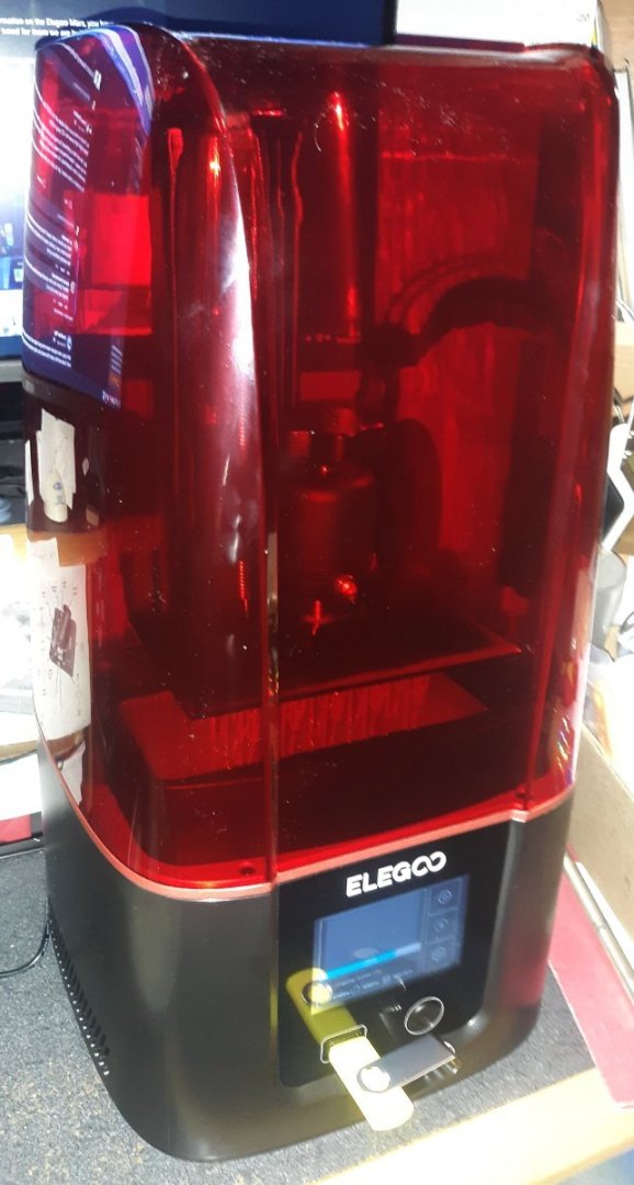
 The Elegoo Mars 3, pictured in post #490. It's been really nice, right out of the box, though I've probably jinxed it now
- 553 replies
-
- 2
-

-
- sloop of war
- constellation
- (and 3 more)
-
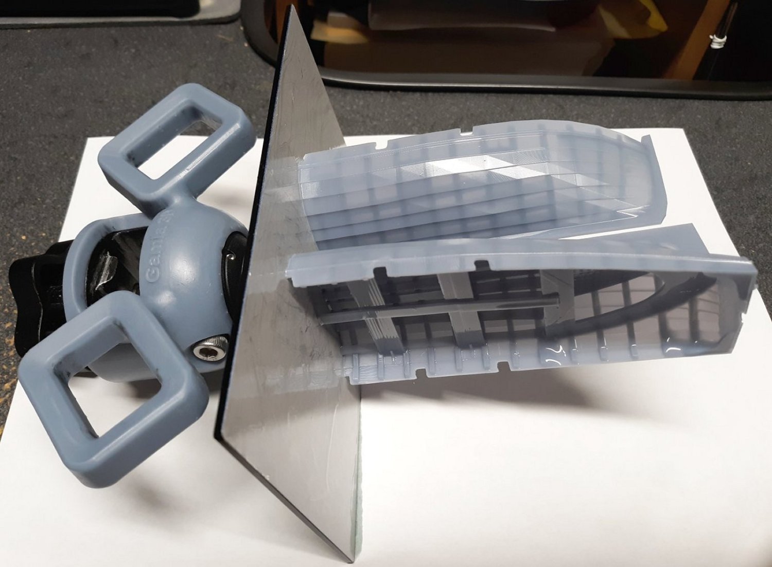
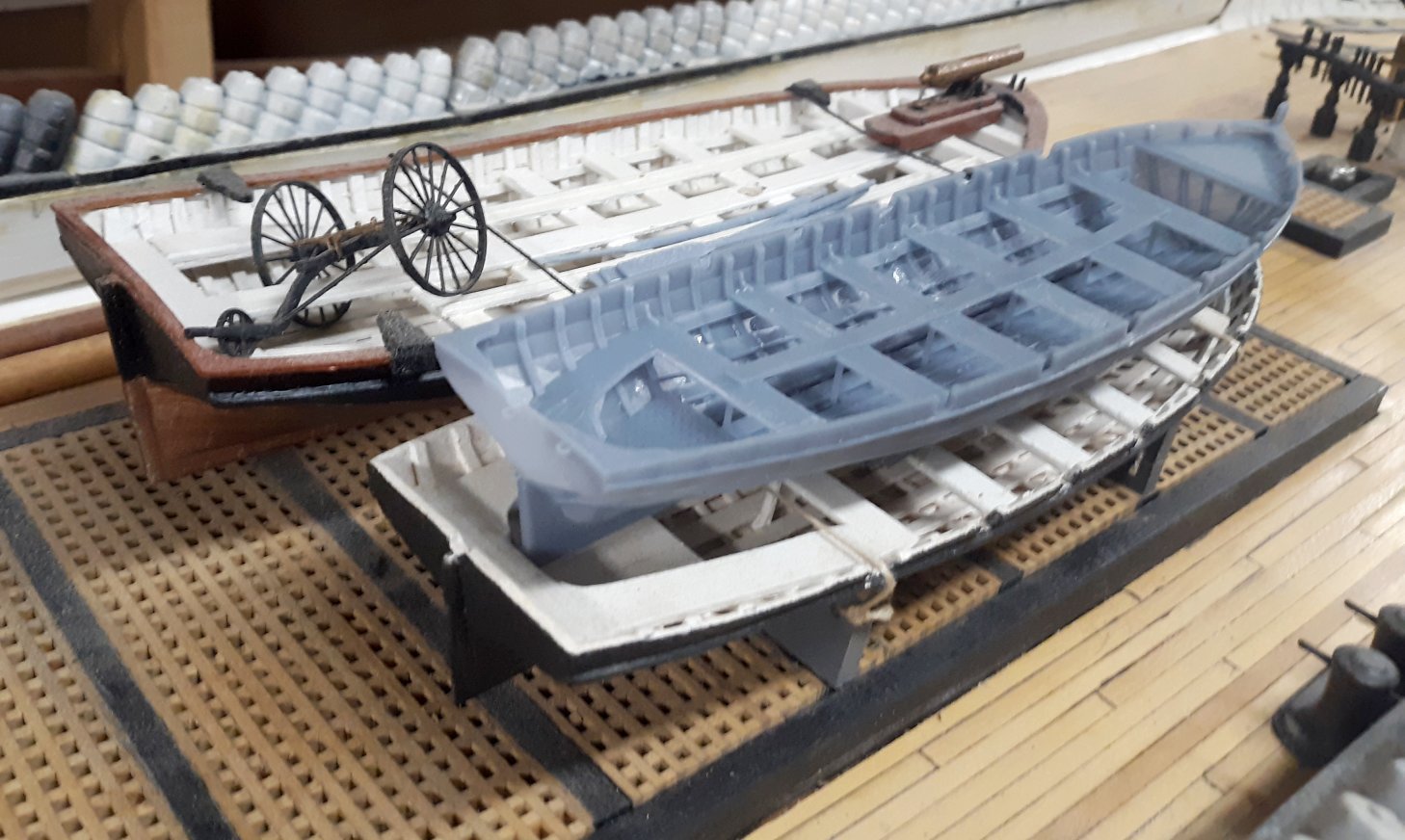
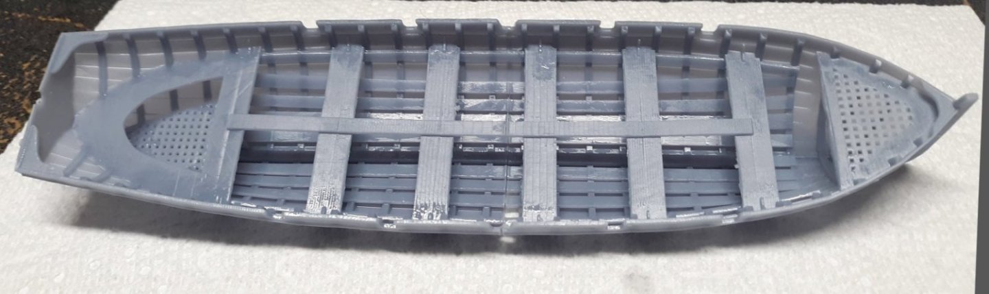
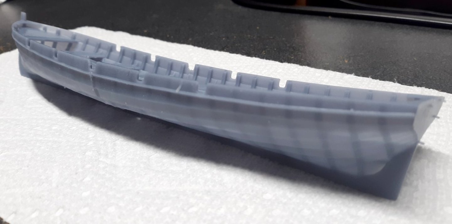
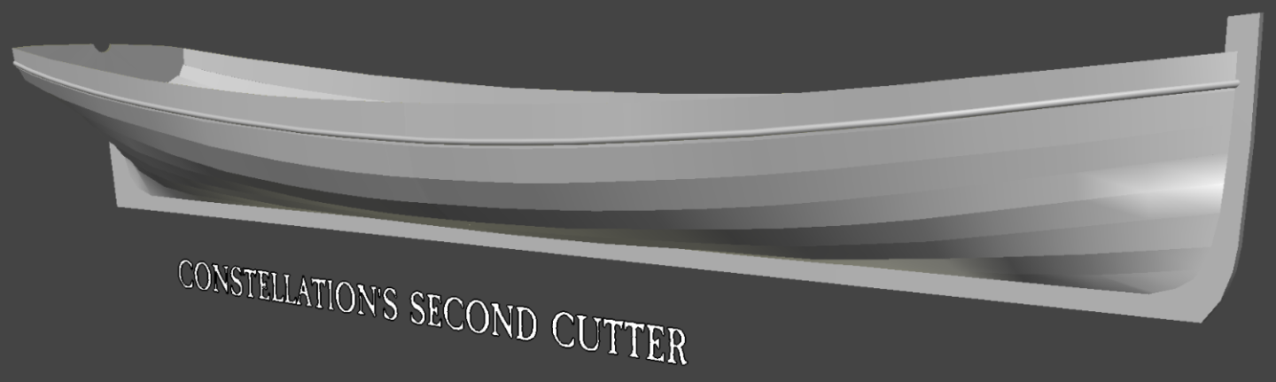
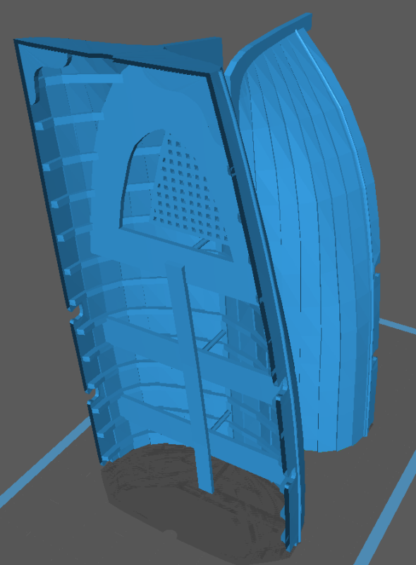
So it's printed! I was concerned the planking would be too thin, but it's fine, as long as the model isn't scaled down. Since I plan to share the file, I'll thicken some things up so it'll scale down to 1:96. I broke off a couple of chips from the bow section trying to get it off the plate, but that's easily repairable at the same time I bond the two halves together. The two halves are just sitting next to each other in these pictures. Once the halves are stuck together and the seam cleaned up, it's priming and painting time! This boat will sit on top of the 1st cutter, on the main hatch, which means making some chocks for it to print along with the oars, rudder, and other little things that'll go inside it.


- 553 replies
-
- 6
-

-
-
- sloop of war
- constellation
- (and 3 more)
-
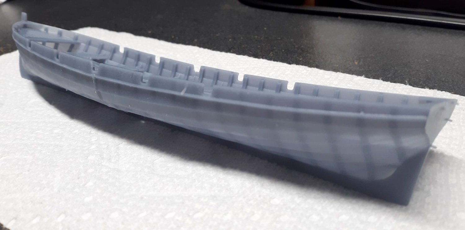
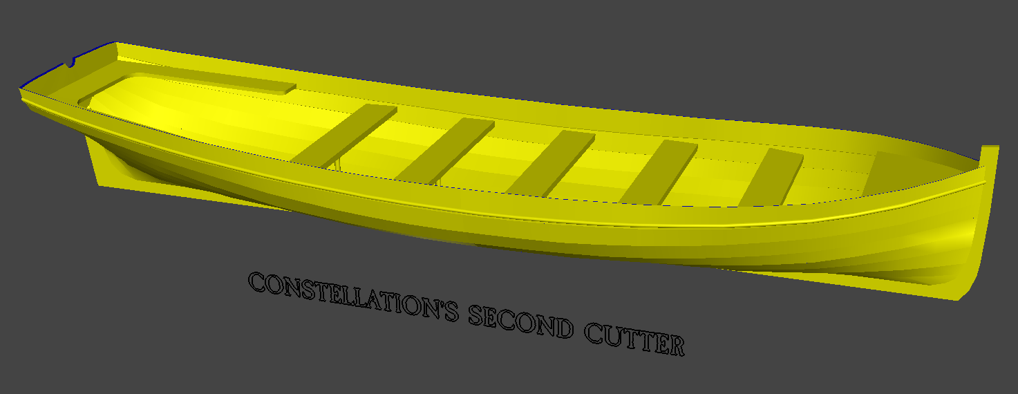
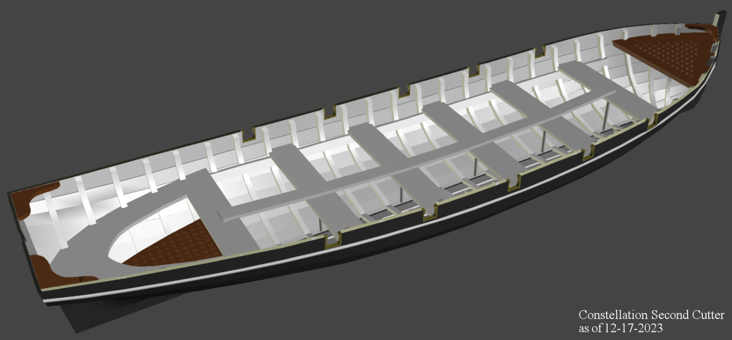
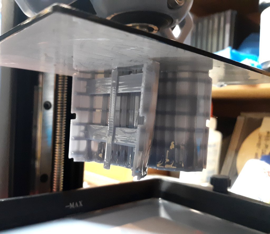
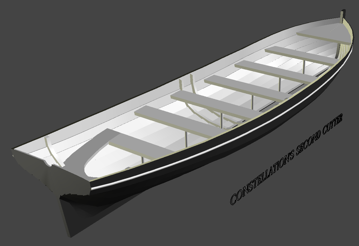
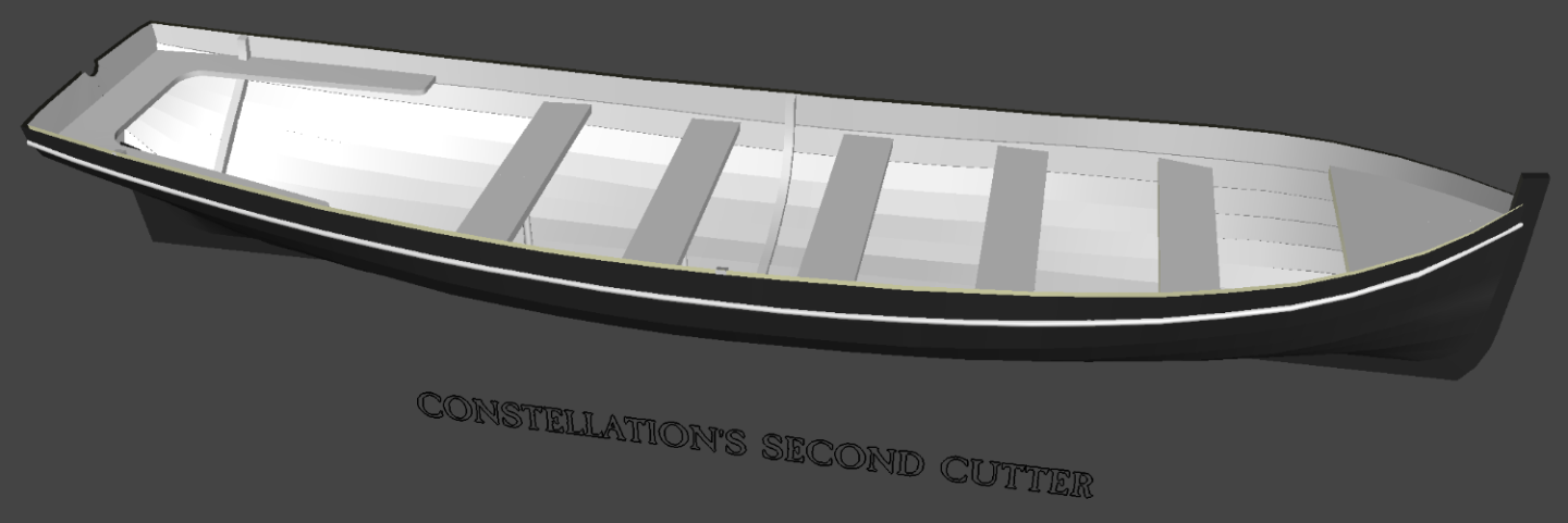
Getting the floor boards in was interesting, but in they went, four to each side; each in two parts; fore and aft; then all mirrored to the port side - so technically I only need to make parts for one side and mirror copy them to the other side. Each seat got knees on either side, and ring-bolts were placed on the transom, two for the rudder pin, and two for the flag. The inner and outer planking was "joined" and the gaps between them closed off, and it was "done." As I type this it's just at 50% printed (the pic was at 45%) and the planking is looking a bit thin. I'll see how it turns out, and if need by thicken the planking shell to 2mm and print it again. The slicer says it'll weight 29.9 grams (1.6 ounces), use $1.05 worth of resin, and take 4h 50m 57s to print.

- 553 replies
-
- 3
-
-
- sloop of war
- constellation
- (and 3 more)
-
I'm using stone tools compared to you Vic. Now, if I could figure out Blender, then I could finally do THIS kind of stuff!
- 553 replies
-
- 2
-
-
- sloop of war
- constellation
- (and 3 more)
-
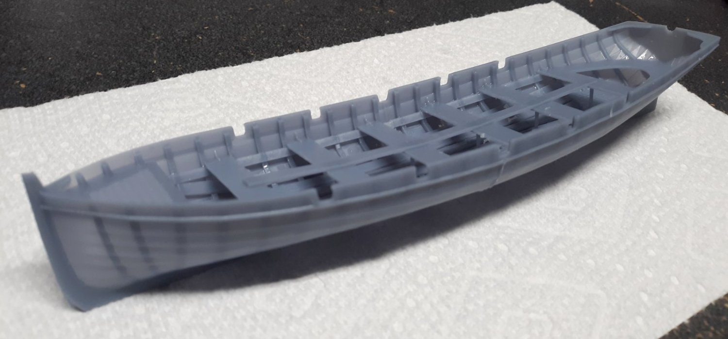
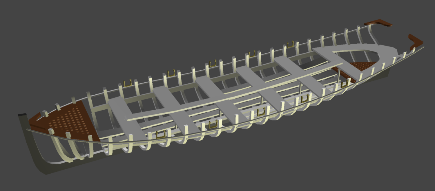
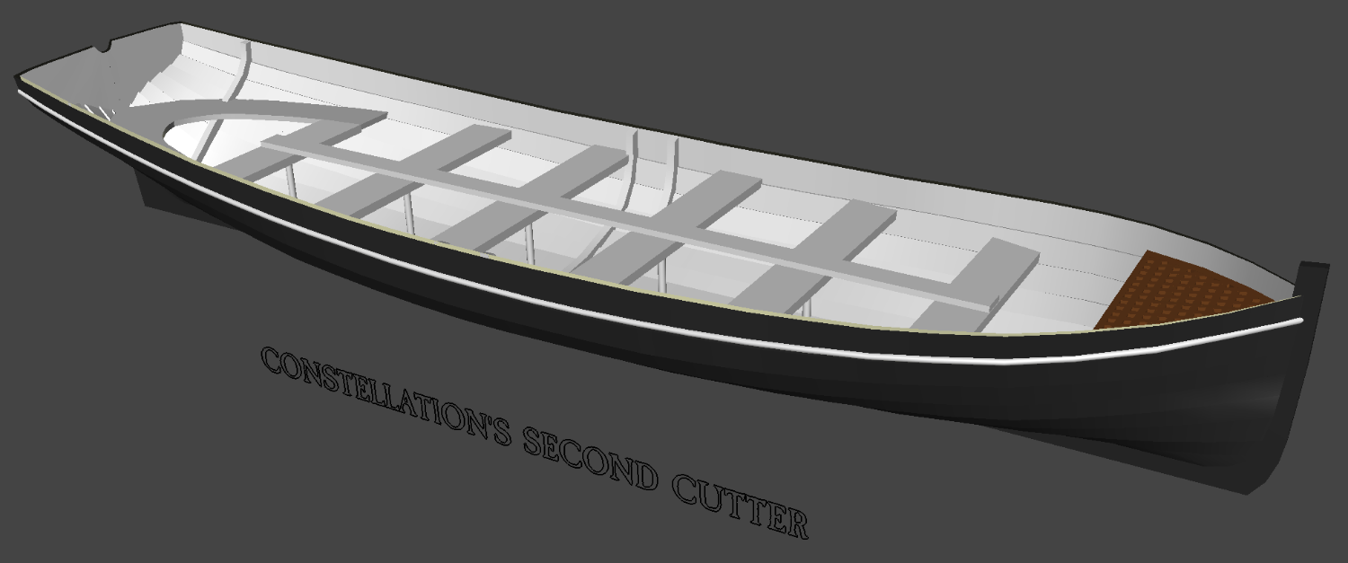
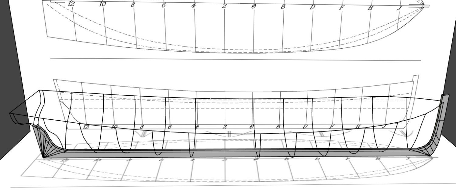
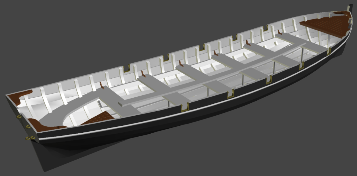
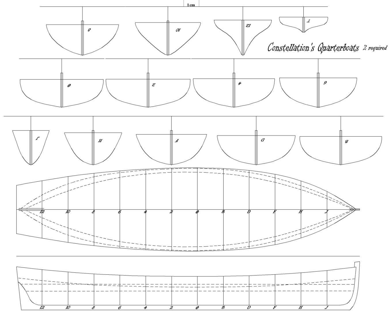
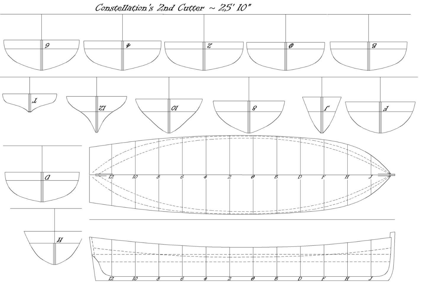
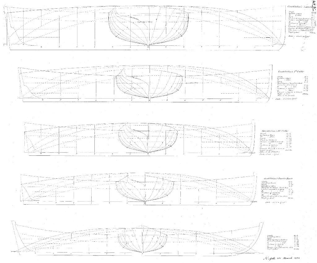
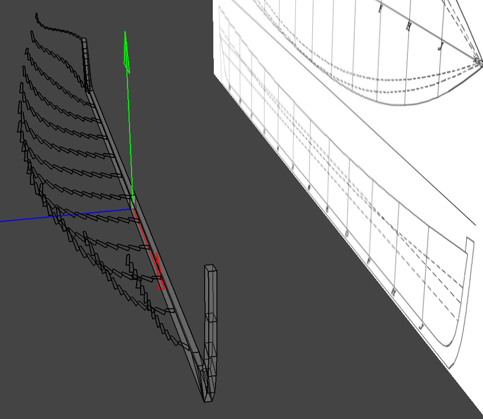
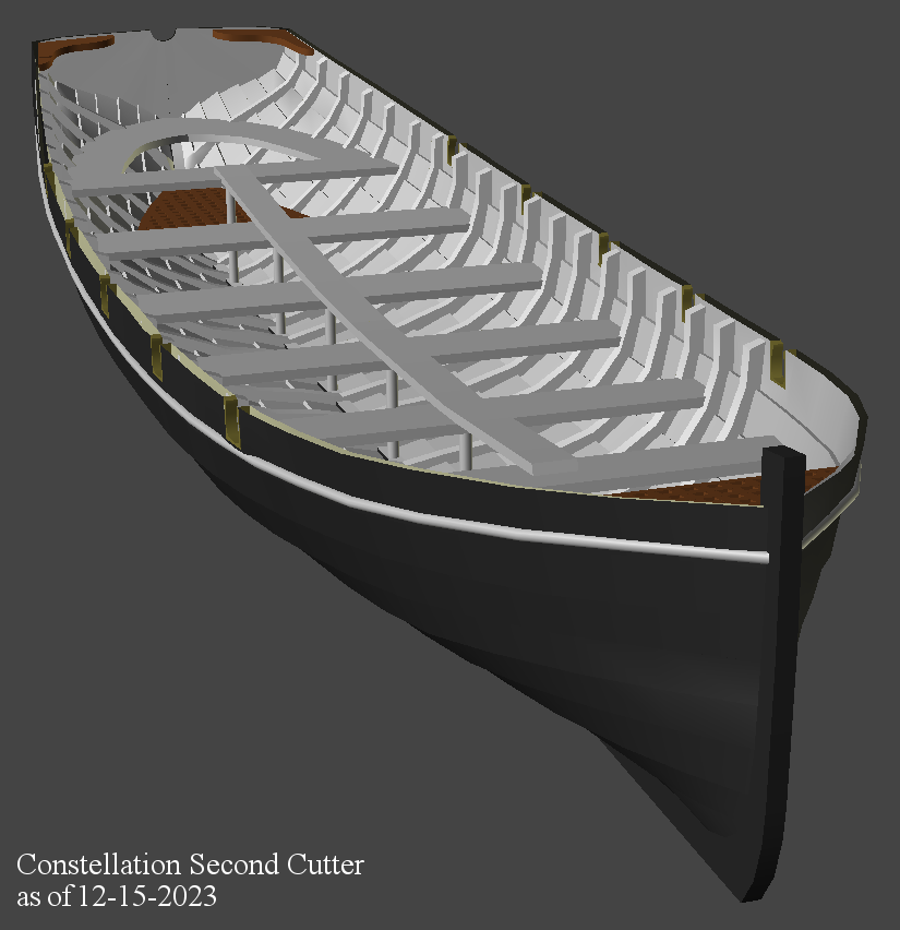
Continuing on with making 3D printed details for Constellation, The plan I'm working from is what I worked up for building the models from the original drawings of Constellation's boats from the National Archives. The launch and 1st cutter were built in wood from these drawings. There' no details shown; rub strakes, seats, decks, oar notches, anything; that I've been looking at manuals, photos (mostly Civil War era), drawings, painting, anything I can find. The first boat built for "Constellation" was the 1st cutter, back at post #493, and the launch around post #727 in this thread. Being able to 3D print now, I though to do the rest of the boats this way on the premise that if something happened to them, I could print replacements. I started fiddling with the 2nd cutter a long time ago, came back to it, and most recently started over almost from scratch. I'm still working in Anim8or because I still haven't managed to wrap my brain around Blender enough to be useful. I basically made the keel, then a "clinker" wire-frame of each station/form, move that to it's place on the keel and connected them horizontally to form the outside face of the planking. Then I made a duplicate of that, flipped it's facings to the inside of the boat, shrunk it a little, and moved some bits around to make the two parts about 1mm thick. Using a "slicing" tool, I made stations between those on the drawing, and moved those points around to try and get a less faceted, ie, a smoother surface, to the boat. Once I had a hull, shaped as best I could, I added a rub-rail, thwarts, a seat aft, which was reshaped later, a foredeck, which got a grating, and started making ribs. It's keep getting details, like floor-boards, knees in various places, notches for the oars, etc. Then, since it's too long to fit in the printer, it'll get cut in half to be printed, and glue it together. As this seems to be moving along, I started on the quarter-boat (that will hang in the davits on each quarter of the ship). I'll need two of these boats, but obviously only need to make one 3D model. December 15th: 22 of 25 ribs installed, grating in the stern sheets, a lot of little adjustments, oar locks, and a check to see if it'll fit in the printer... December 17th: All the ribs are in, the last two are cant frames, and took a couple of tries to get lined up. Redid the forward grating, and added a breasthook. Seat clamps are in, but there's floorboard yet to do, along with some hardware items like a flag-holder on the transom and gudgeons for the rudder. The rudder itself, oars, and some other things will be printed separately.


- 553 replies
-
- 4
-
-
- sloop of war
- constellation
- (and 3 more)
-
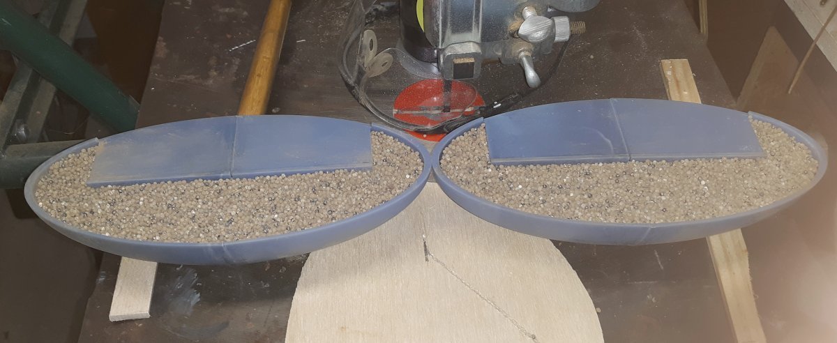
The lead shot I have is reclaimed material and has a lot of dirt in it. I shook it through a sieve several times today, but I'm not washing it because it takes a very long time to get it dry, and I don't want to seal moisture inside this thing. So here's both halves mostly filled with lead, and a pic with the fin on it. It was too cold tonight to pour epoxy, but if it gets above 55°f tomorrow, I'll give it a try.
- 79 replies
-
- 2
-
-
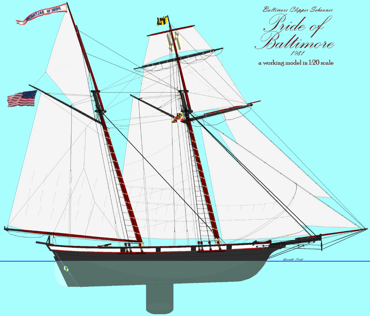
- pride of baltimore
- privateer
- (and 3 more)
-
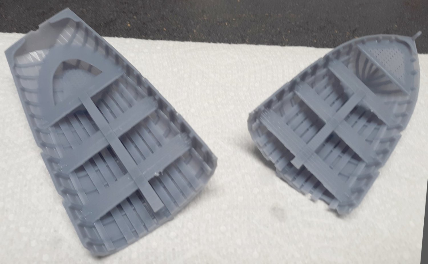
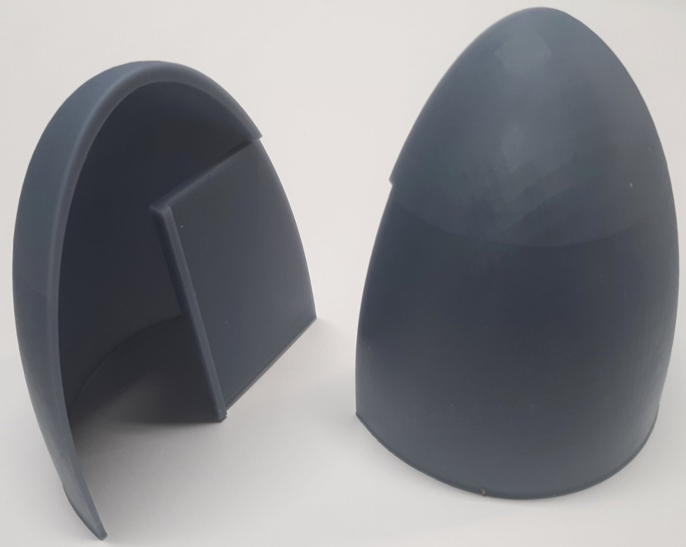
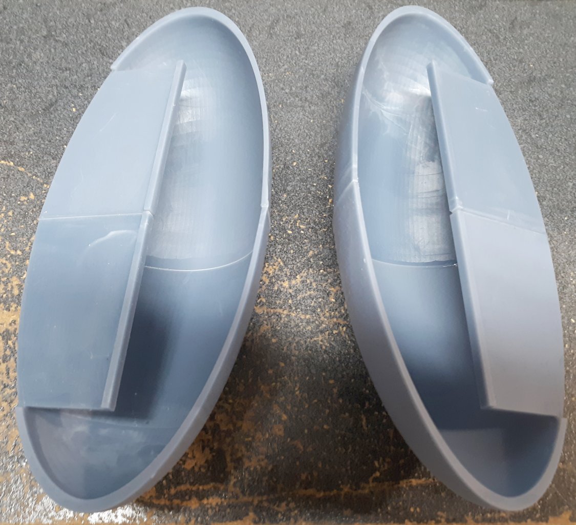
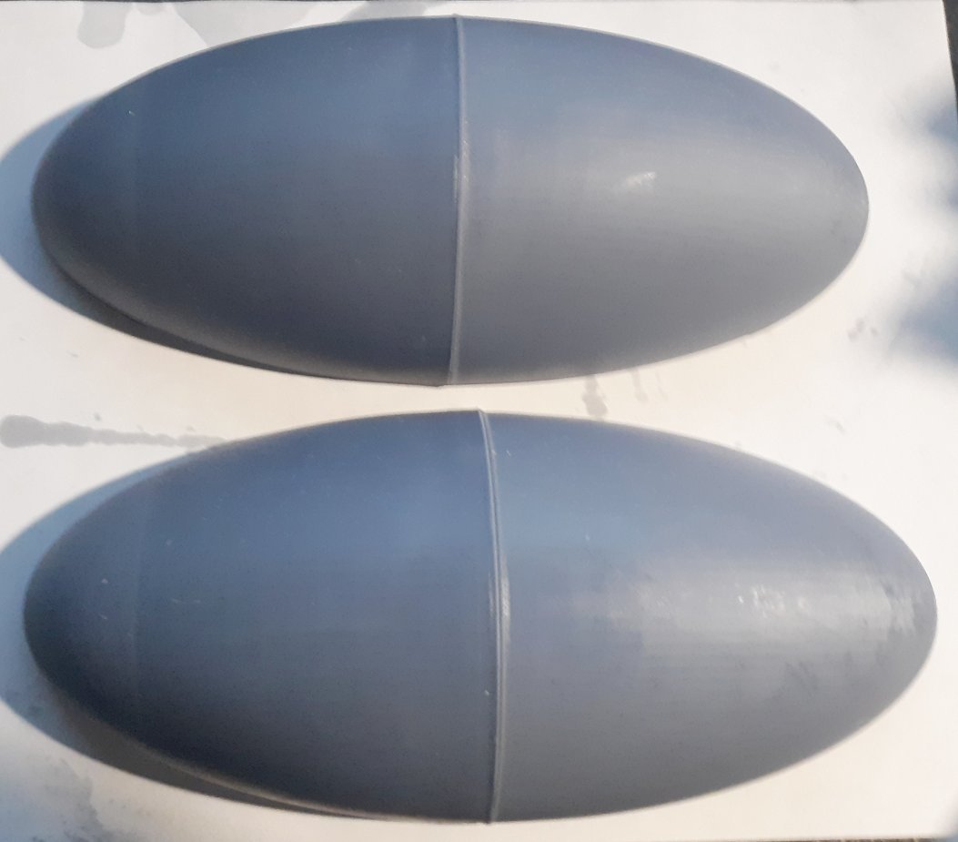
Finally all four parts are printed and two quarters bonded together to make two halves, left and right. There'll be some sanding involved, but that was expected. Now it's time to load it up with lead.

- 79 replies
-
- 1
-
-
- pride of baltimore
- privateer
- (and 3 more)
-
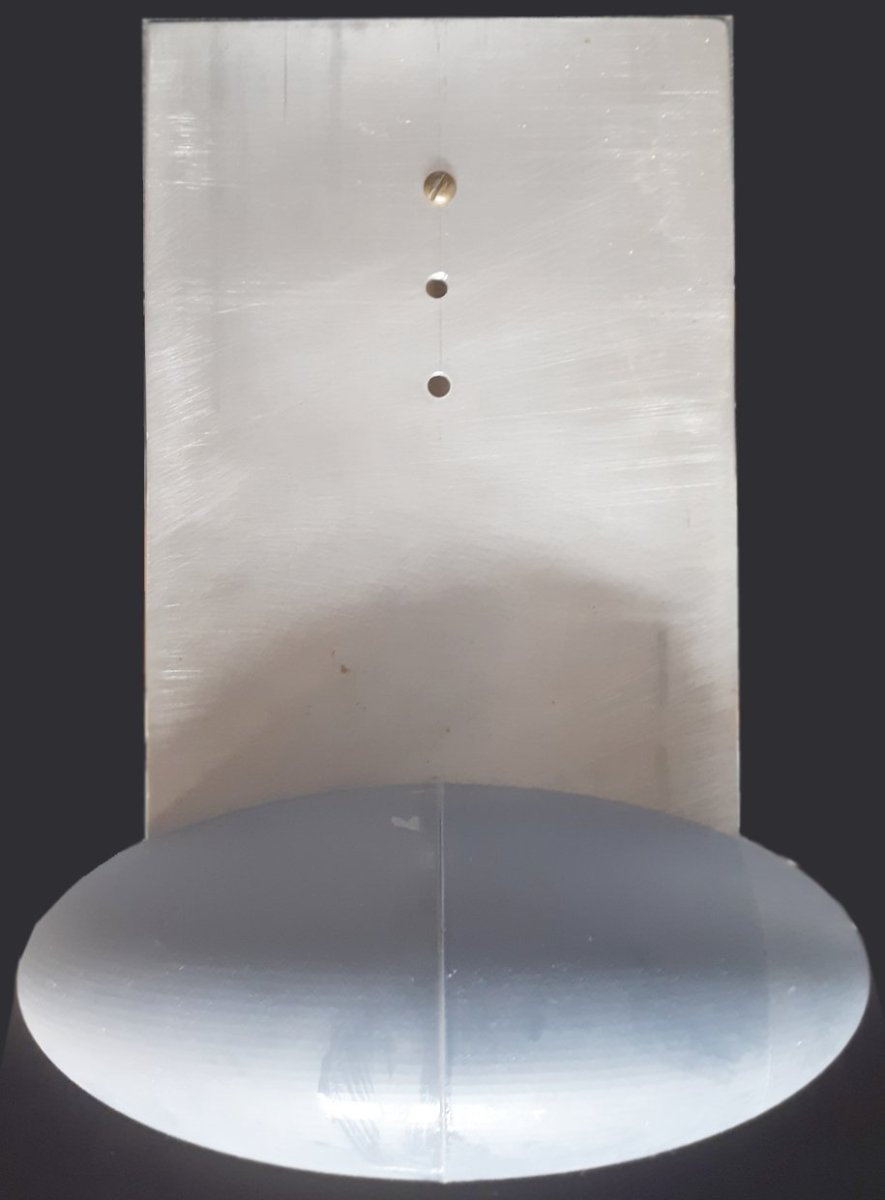
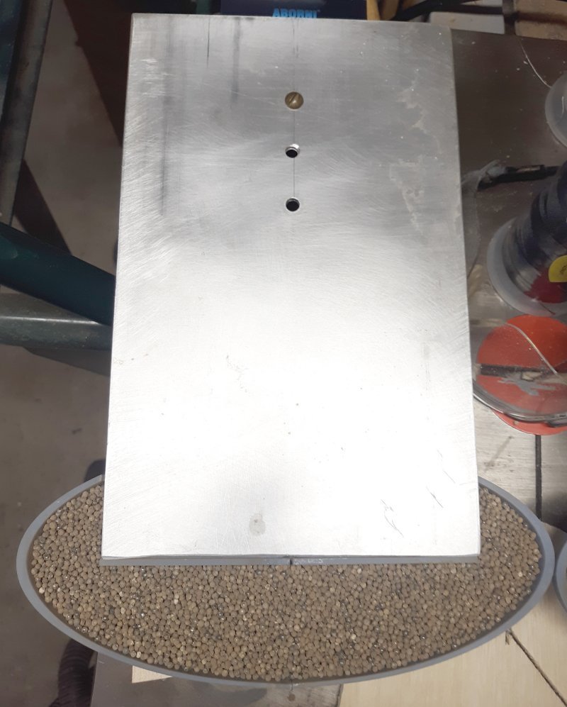
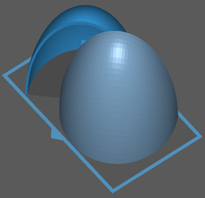
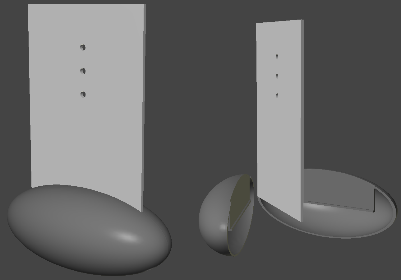
Most of the model's ballast weight will be in a bulb on a fin at the bottom of the boat. The fin slides into a sort of center-board trunk built into the model some years ago, back around post #7 of this log. The fin itself is an aluminum plate measuring about 153mm x 245mm x 4mm. The fin is placed at the hull's center of lateral plane. Last post I used a brute force method to determine the amount of weight the bulb will need to be (25pds/11kg) I intended to sand cast the lead bulb in two halves, but that would require getting the tools and equipment for the job; a pot and burner to melt the lead, a ladle, casting sand, gloves and an apron, etc. Simpler yet, is to cast the lead shot in epoxy, but I would still need a form. Years ago, I would put the lead in some sort of container, like a 35mm film can, or in the case of Constellation a PVC pipe. That's got to be the safest way to handle this without requiring special equipment. Suitable containers that can hold 25 pounds of lead shot aren't readily available, but 3D printing is... So I started making a 3D model ball with inward facing surfaces, pulled and stretched it into a nice symmetrical ellipsoid, and went surfing for how to determine it's volume. I found a great web site that does just that, and played with the numbers till I got a volume of about 60.62 cubic inches, which multiplied by lead's weigh of .41 pounds per cubic inch, gave me 24.9 pounds. I adjusted my 3D model to those dimensions (a=50mm, b=105mm, c=45mm). I built a model of the fin plate as a reference, then cut the bulb into left and right halves, deleting one of them. I copied the remaining half and pasted it over the original, enlarged it, and flipped the surfaced so it was facing outward. The gaps between the two shells were closed up so it was a solid shell about 4mm thick. I built some structure to seat the fin inside the bulb, them cut the completed half shell into halves again, ie, quarters to wind up with 4 identical quarters , two of which will fit the volume of my 3D printer. As I write this, the first two pieces are on the printer with just 4 out of 6 hours left to print; then I'll print the other two quarters. When done, I'll bond two quarters each into a right and left half; fill each half with lead shot; pour in epoxy to solidify everything, then bond the two halves on the fin.
- 79 replies
-
- 1
-
-
- pride of baltimore
- privateer
- (and 3 more)
-
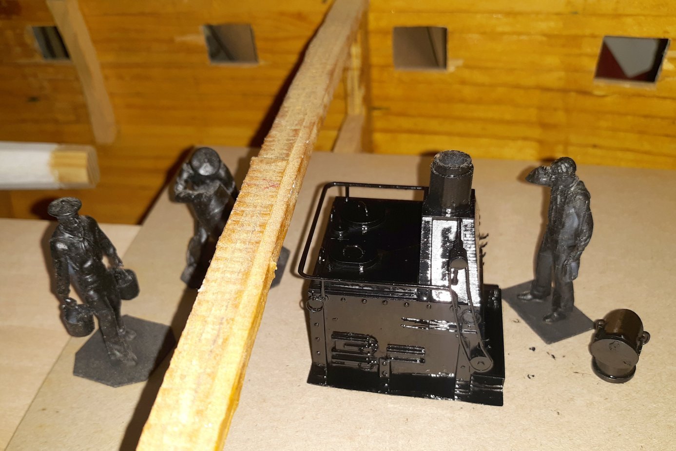
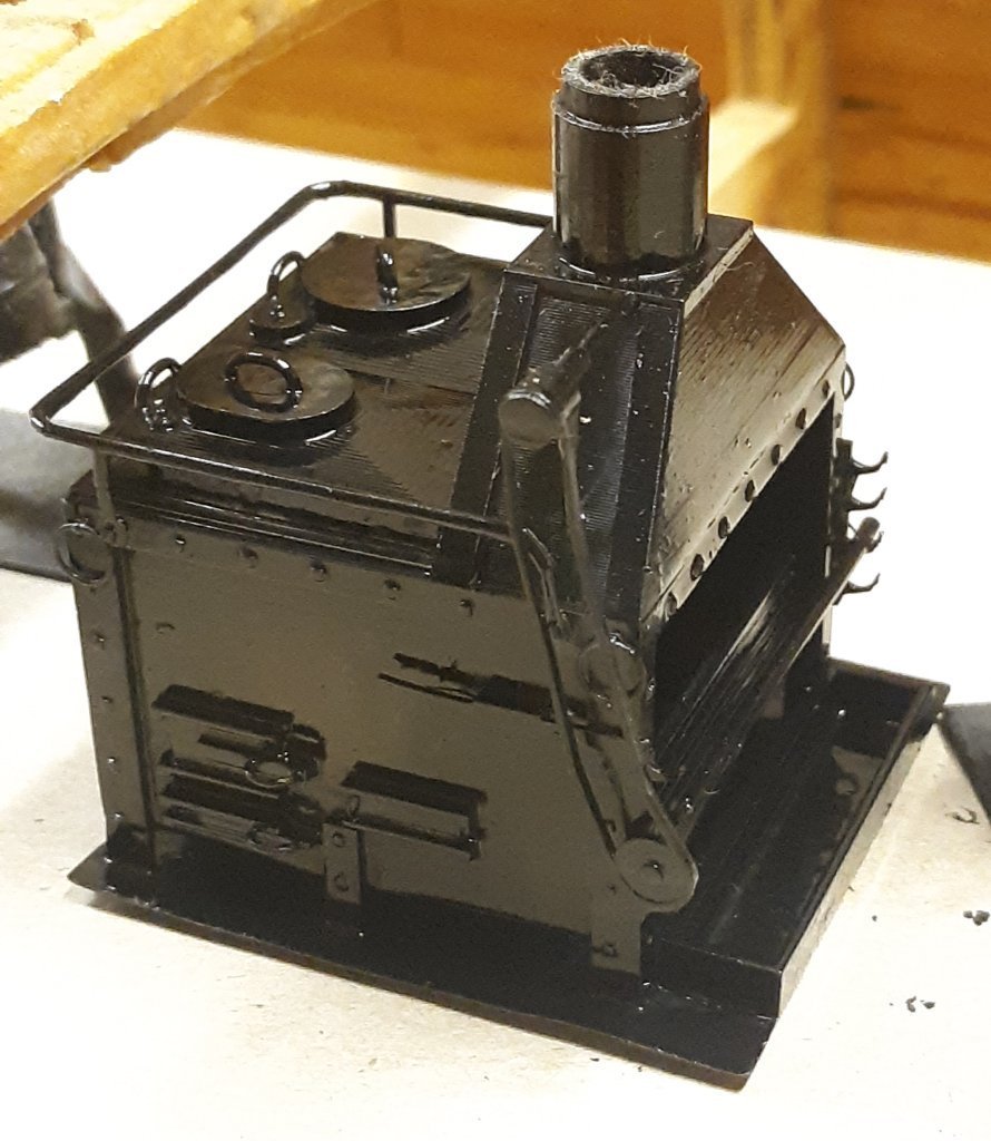
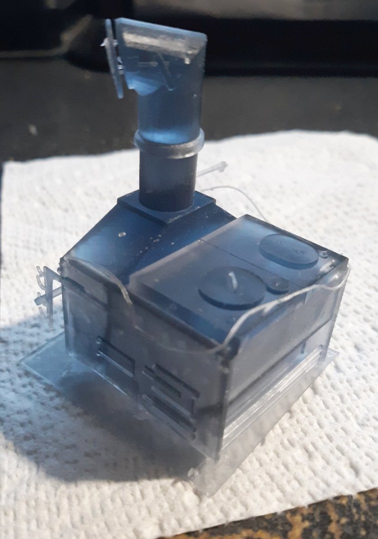
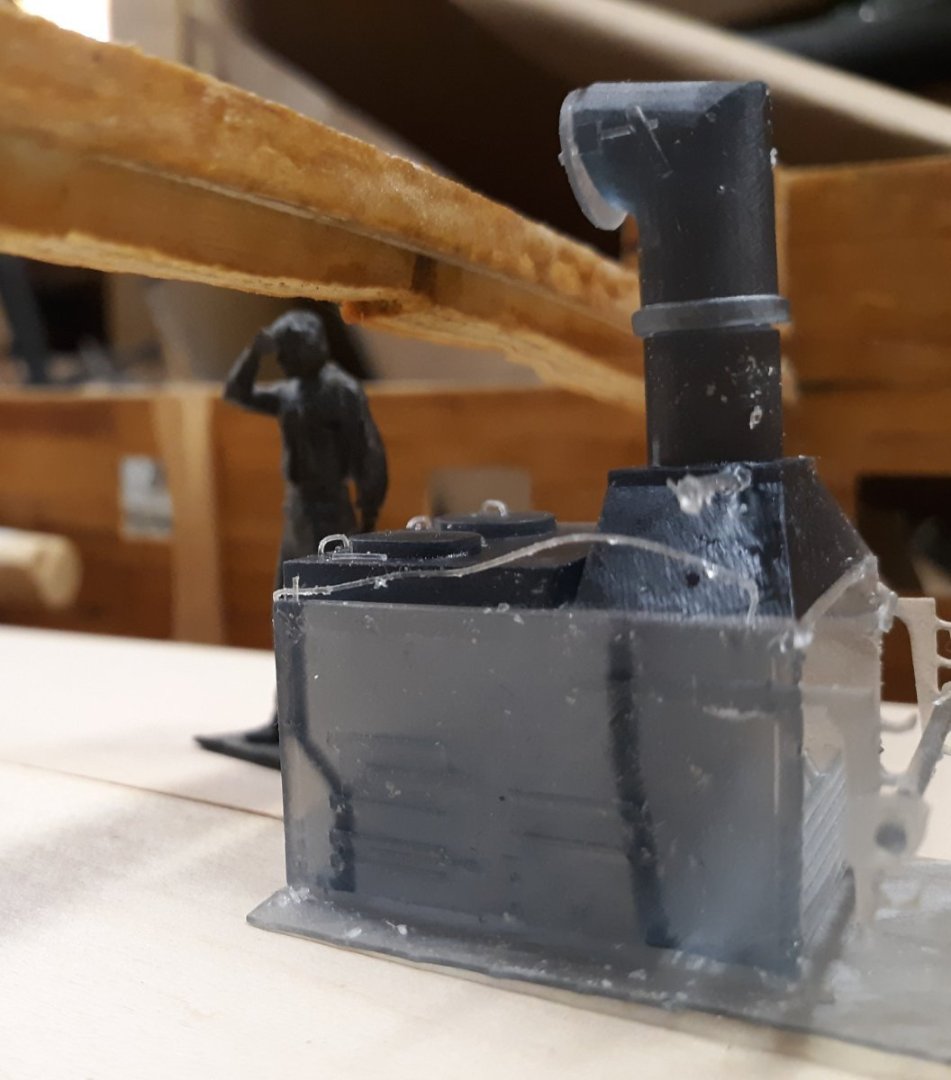
I adjusting the 3D model to Lavery's chart and printed it. It looks more in scale with the hull now, and the details certainly printed better than the first try. The grills pulled a bit during printing where they didn't do that on the previous print, because of how it was oriented in the printer. Some of the details are still a little frail, but they're all there and serviceable. I posted the STL file on Thingiverse though I can't say how well it'll resize to smaller scales. Here it is with a coat of paint, and with Constellation's crew check the fit.
- 97 replies
-
- 4
-
-
-
- macedonian
- frigate
- (and 2 more)
-
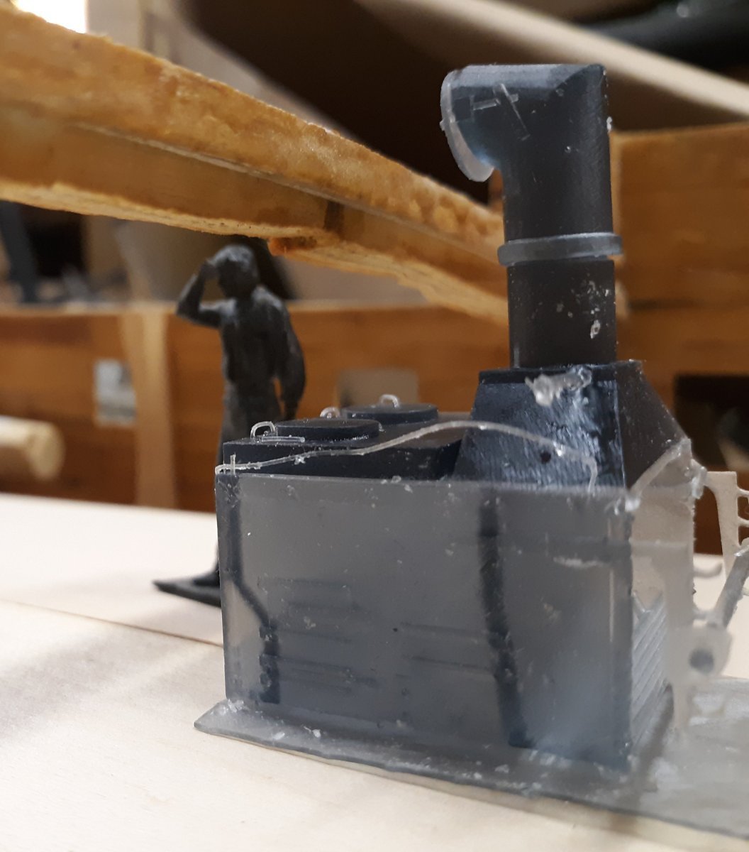
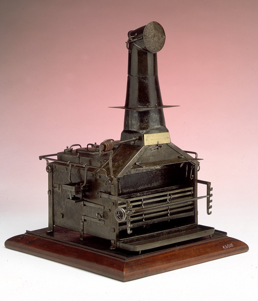
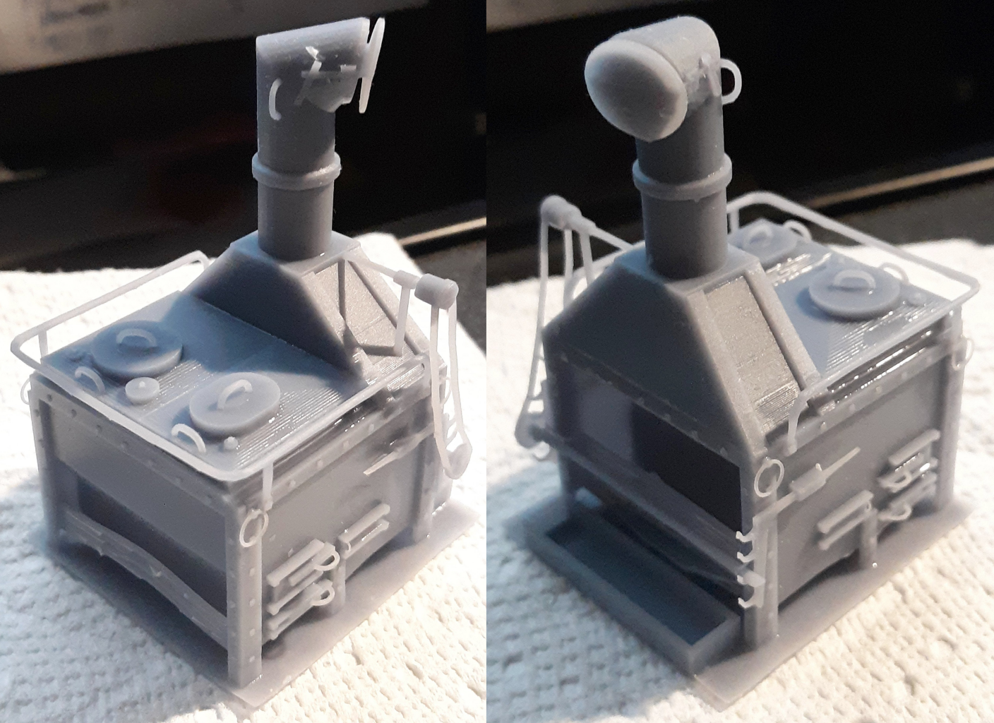
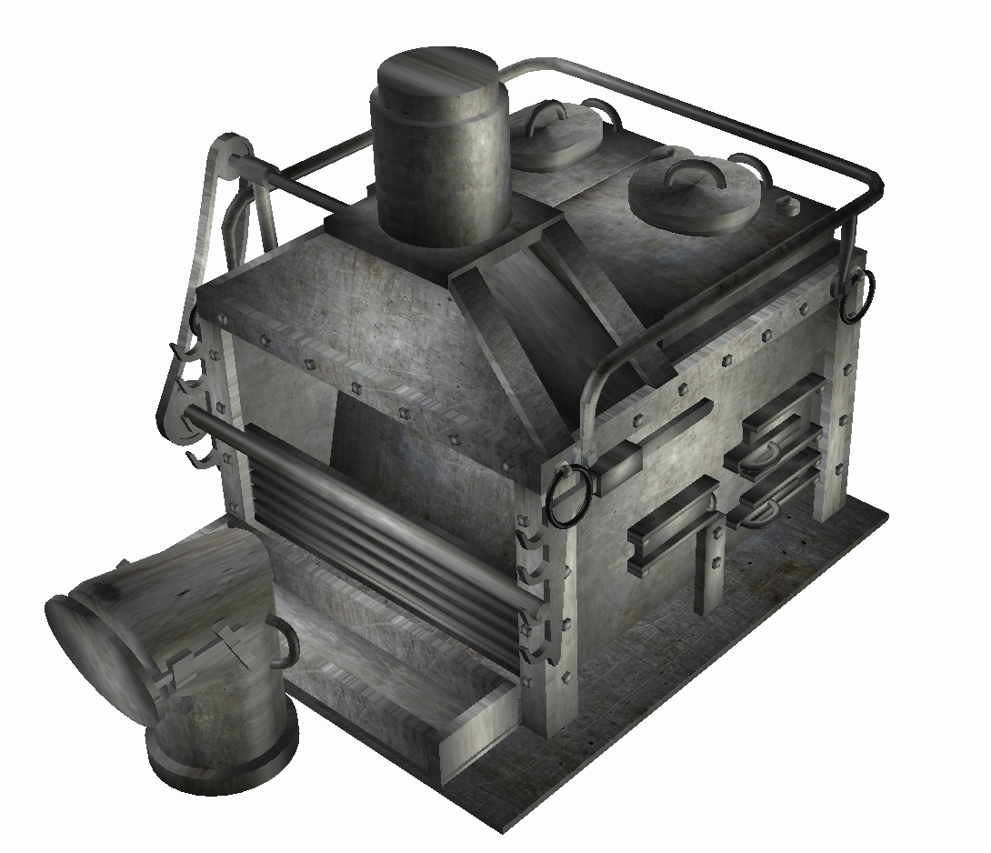
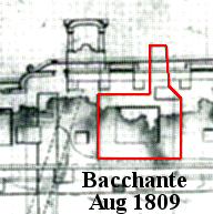
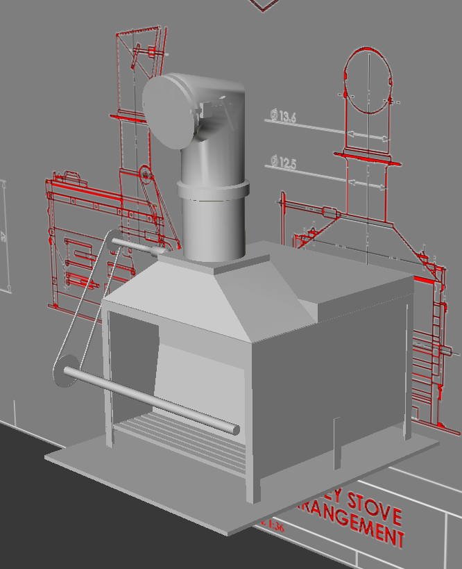
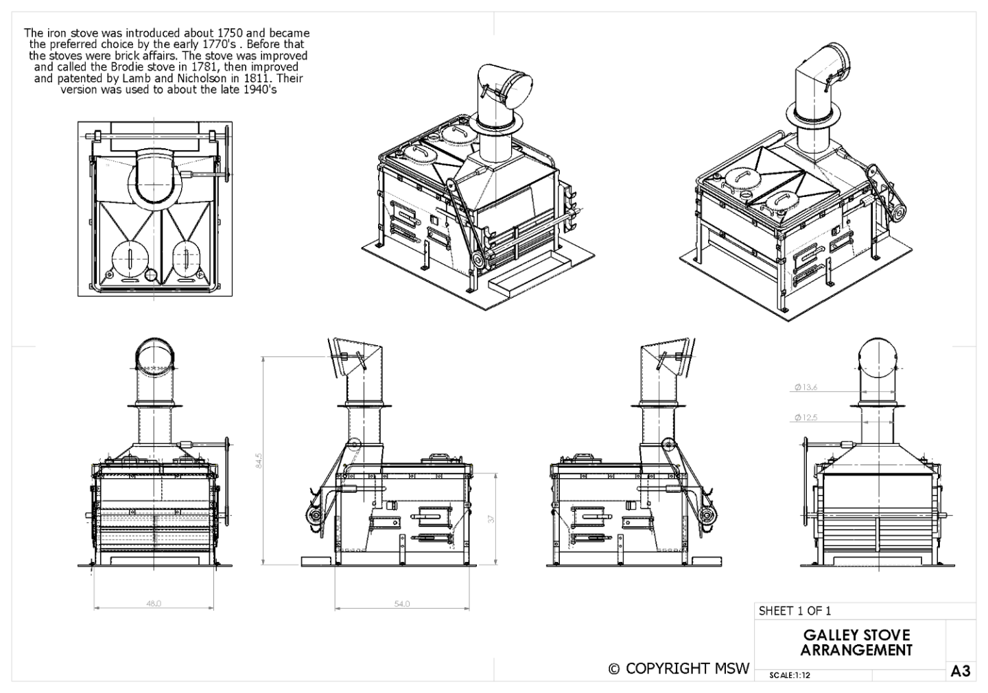
Before putting more details into the stove, I decided to print it and make sure everything would print.... A lot of the details were too fine; the grab-rail, handles, rotisserie sprockets and chain, etc. The charlie-noble, which is a separate part, fit perfectly though I went back to the model an beefed up the details; thickened the rail and handles, thickened bots and straps, rotisserie parts, etc, and for kicks, added an iron texture to make the screen shot look good, though it has nothing to do with printing it. The whole thing seemed a little small to me, and remembering I have a copy of The Arming and Fitting of English Ships of War 1600-1815 by Brian Lavery, which has a great chart of stove dimensions for various gun-rates of ships on page 198 (2006 edition). On that chart, for a 38 gun ship; the stove's body width should be 56 (48) inches; the length 57 (54) inches, and the height to the top of the flat sides is 48 (37) inches. The height to the top of the pyramid duct is 64 inches. The height of the chimney isn't given for ships of less than 80 guns. (The numbers in parens are the measurements given in the MSW drawing attached a couple of posts earlier.) On another note; the book mentions Lamb & Nicholson stoves, but shows no image, diagram, or description of one. Here's a portion of the "Inner Works" of another Lively class frigate, the Bacchate, launched about a year before Macedonian, with the stove outlined in red. The MSW dimensions are a little smaller than the dimensions given by Lavery for a 38, mostly in height. Before printing it again, I'm going to adjust the model and check the height of the chimney on the Macedonian model itself.
- 97 replies
-
- 4
-
-
- macedonian
- frigate
- (and 2 more)
-
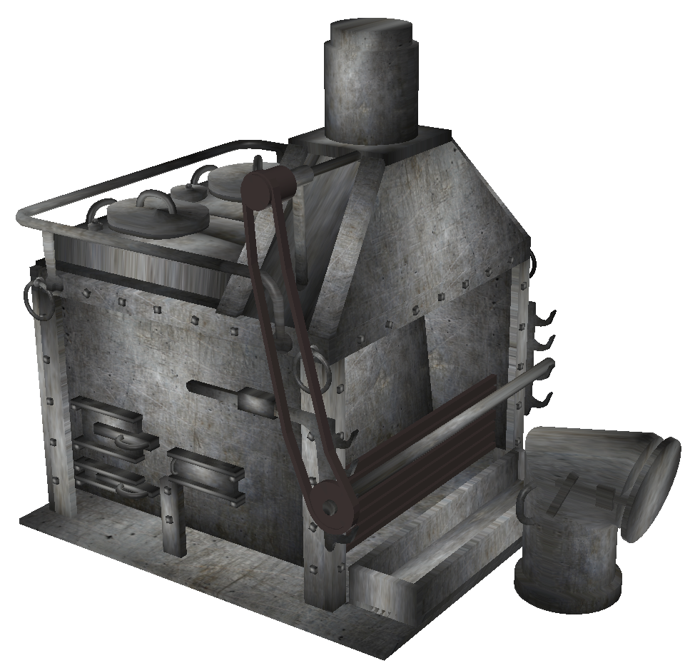
I'm only going for "implied" details on this model, and that's almost done. I made the top of the chimney a separate part and will size it to be attached after the stoves and the forecastle's installed. There's a brace for the spit-drive arm to make, and a couple of flanges on the feet, and it'll be pretty much done and ready to take a shot at printing.
- 97 replies
-
- 2
-
-
- macedonian
- frigate
- (and 2 more)
-
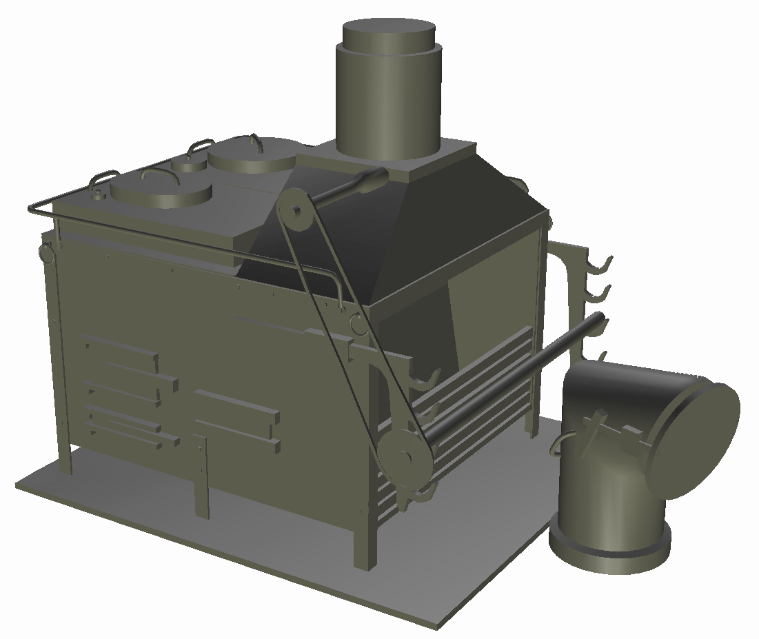
I'm still trying to figure Blender out enough to make viny ornaments for the bow of Constellation and Macedonian, but when the frustration gets to be too much, I slip back into Anim8or and work on something my simple mind can handle... This time it's a galley stove for Macedonian. I found decent drawings online, that apparently originated here; and photos of a model from the National Maritime Museum in Greenwich to base my 3D model on. Unlike Constellation, Macedonian will have her gundeck modeled with guns and other details, such as this stove. I looking for source material to base a model on, it seems the same year Macedonian was launched (June 1810), a new stove by Lamb & Nicholson was being fitted into British warships, but I haven't been able to find any drawings or images of a L&N stove to model from. Also, I assume the stove would have been requisitioned some time before the ship's launch, and would therefore more likely be a Brodie type. If someone can show Macedonian got an L&N stove and direct me to drawings of such a thing, I'll gladly model that. So here's my progress after a couple of hours work. All the details will go into the model, but nothing with be "functional," that is doors, lids, chain drive, etc won't open, be removable, or move. It'll barely be visible peering through the gunports or main hatch, but at 1:36 scale, leaving off too many details would be just as noticeable, as I did consider just making a black brick shaped like a stove.

- 97 replies
-
- 2
-
-
- macedonian
- frigate
- (and 2 more)
-
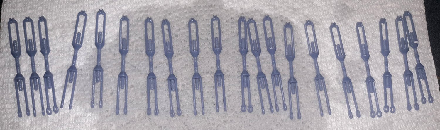
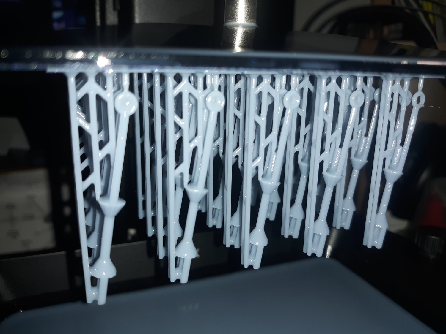
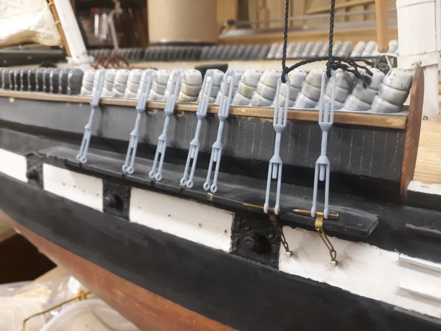
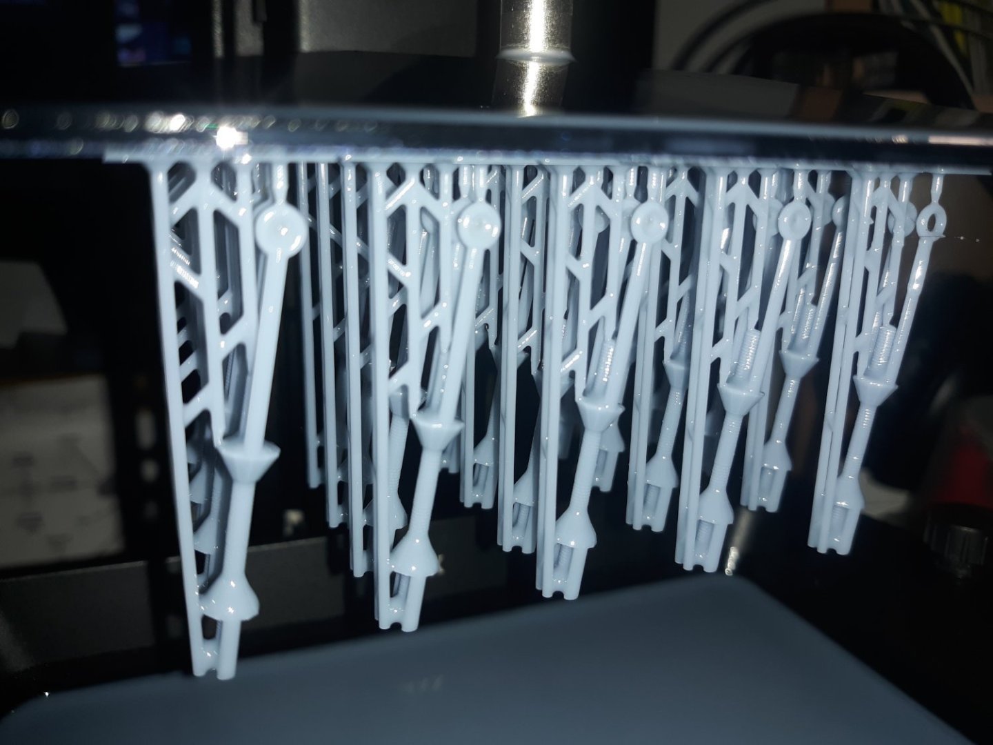
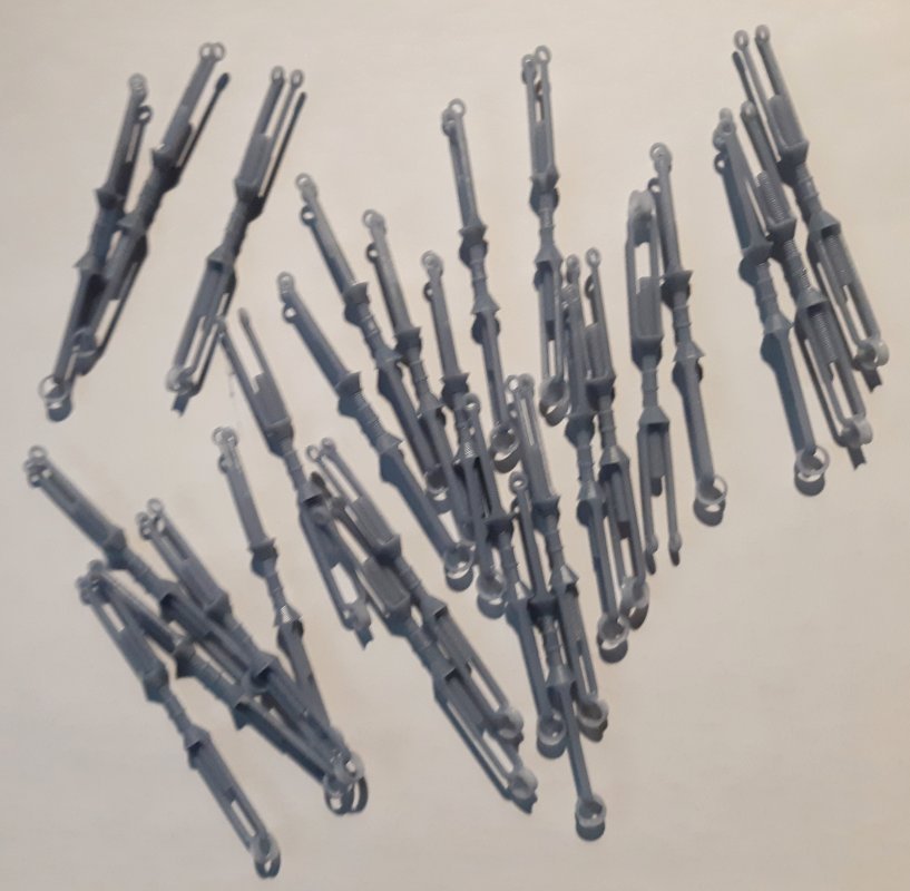
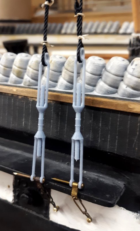
I got a new 3D printer (Elegoo Mars 3) that has more print volume (larger prints), more resolution (better detail), and actually cost less than my original printer did. First thing, I printed a test batch of "draft" screws as above. They printed perfectly, though the model needs some adjustment; the eyes at the bottom needed to be smaller, and the thimble at the top needed to be bigger around, per the photo of the originals. I also had them print standing almost straight-up, meaning more layers, meaning more more time to print - it took about 5 hours to print these because of that. I attached a pair to chainplates and put them on the model to see how much tugging they would stand. They seem to be tough enough, especially once they're all connected by a sheer-pole. The 3D model's updated and I'll print it more one it's side to take less time to print. I enlarged the thimble, reduced the eyes, and thickened the screw a little. I also reshaped the arms a bit. 30 of them printed in 3 hours 20 minutes, and I temporarily put two on the model under tension to see how they hold up.

- 553 replies
-
- 8
-
-
-
- sloop of war
- constellation
- (and 3 more)
-
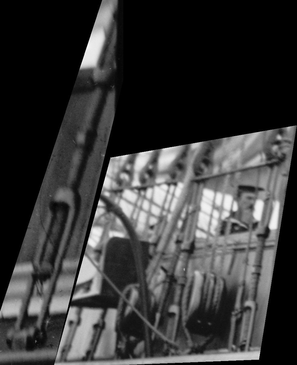
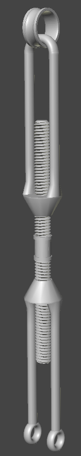
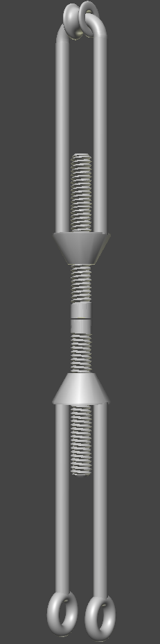
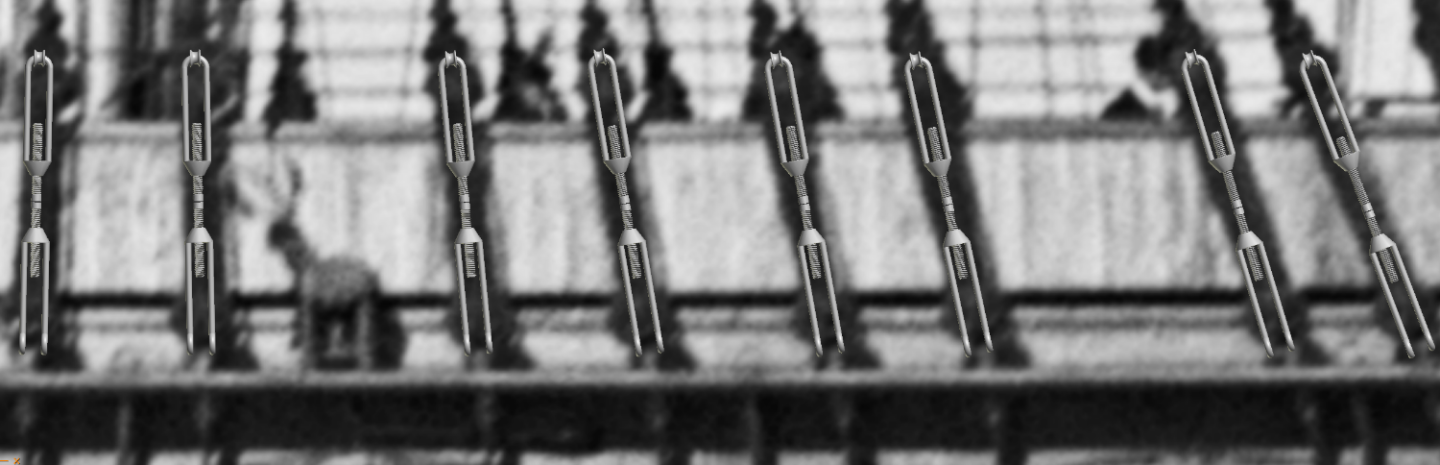
Finally got a chance to work on a draft of the Constellation's rigging-screws. It will average 2.5" (63mm) long. It won't be "functional" that is they won't be adjustable but rather one solid piece. If a test print works out, the length will be adjusted in the software to account for the different angles the shrouds take up so the tops will level with each other, basically, I'll print a set for each mast, port & starboard.

- 553 replies
-
- 3
-
-
- sloop of war
- constellation
- (and 3 more)
-
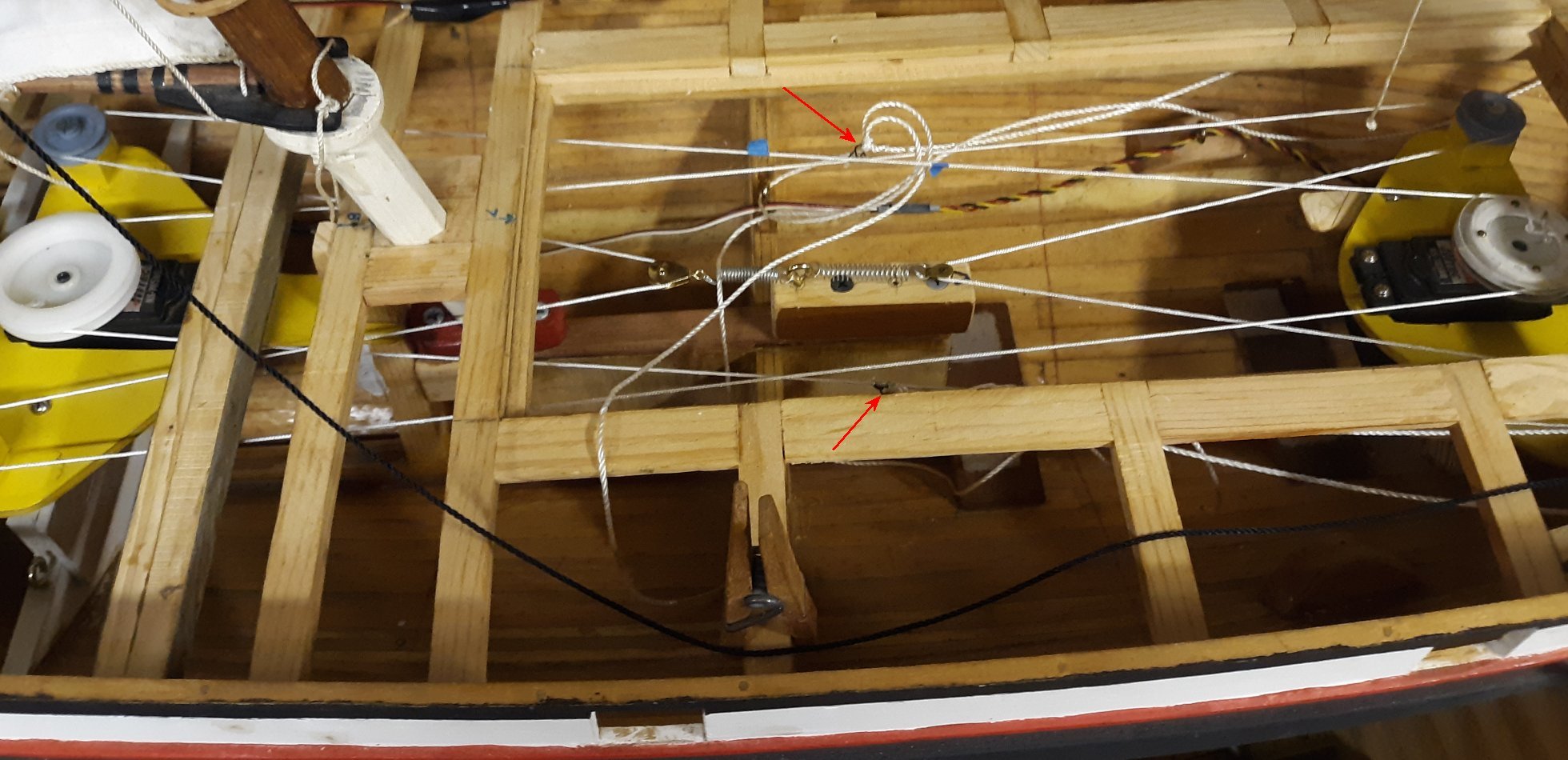
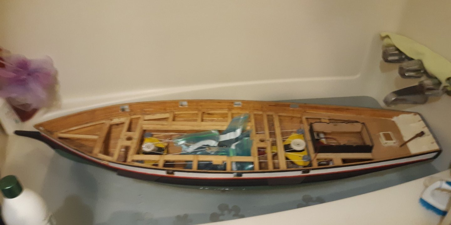
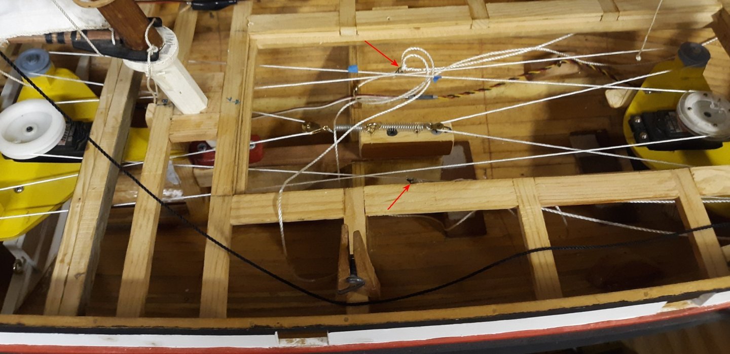
I was going to slap together a temporary trough to float the model in to determine what the weight the bulb on her fin would need to be, but I'm either up to my neck with other stuff or too worn out to motivate myself through the shop door. I finally put the model in the tub, in which she barely fit, and figured out the bulb will need to be 25 pounds (11kg) to sit about 1/2" below her painted water line. Adding the battery and some lead-shot bean-bags will trim her where I want her for sailing. I'm still up in the air on how to make the bulb; whether to melt and cast the lead, or cast the lead in epoxy. I'm leaning toward the epoxy casting, and have ordered the epoxy to do the job (and to do some other jobs like repair the pram). In either case it will be made in two halves and somewhat "wing" shaped; something like this model's, though Pride's fin is longer, wider? Meanwhile, the masts are back in and I've been playing with the sail controls again. I seized dress hook loops to the winch lines (red arrows) to attach the sheets and figure out how to keep everything neat and untangled.
- 79 replies
-
- 5
-
-
- pride of baltimore
- privateer
- (and 3 more)
-
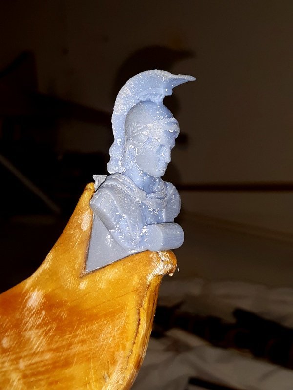
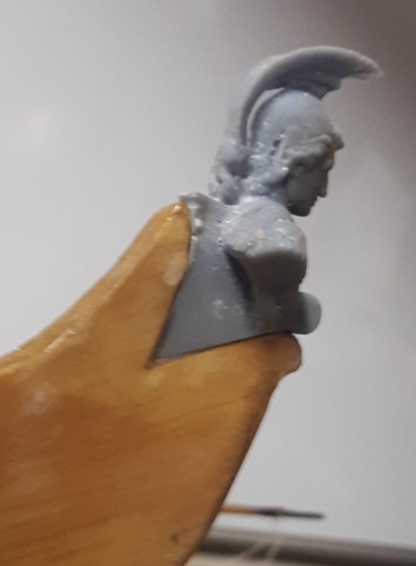
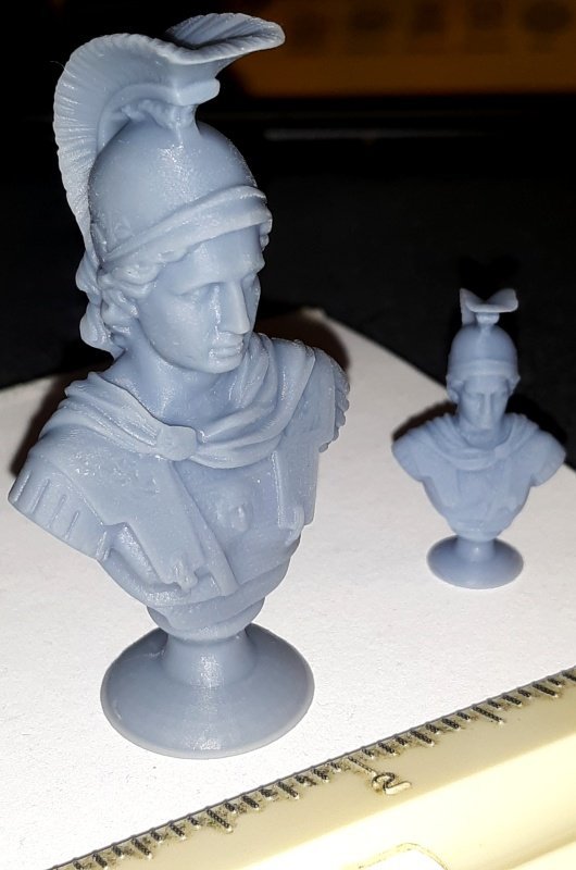
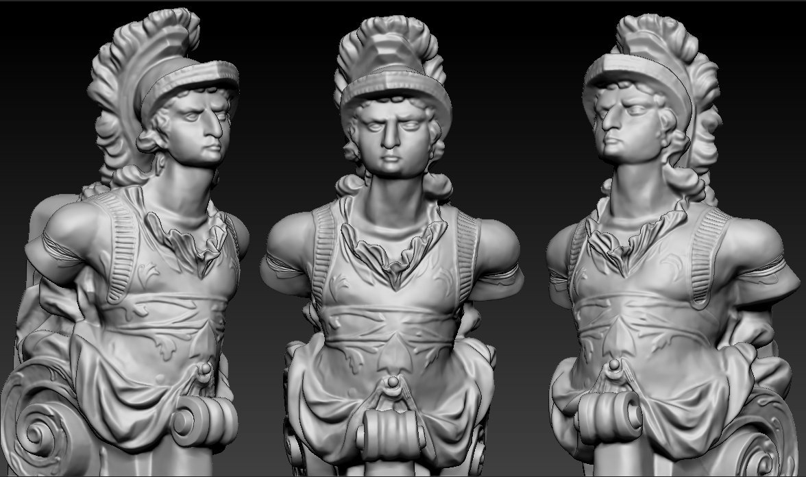
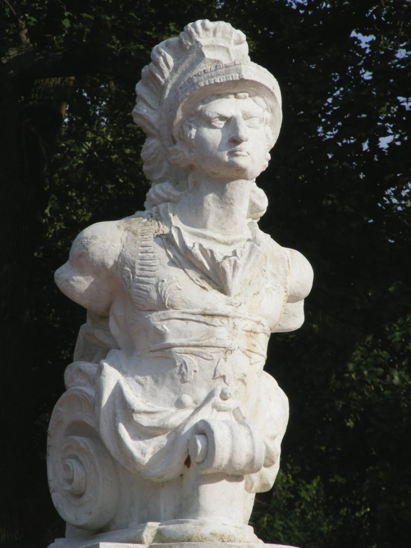
Some years ago someone scanned the Macedonian figurehead at the US Naval Academy. A reproduction has since been made so the "original" will be kept indoors, and the repop up on the pedestal outside. They somehow found me and offered to 3D print one for my model for a mere $300. Mind you, that's a for a 2 inch tall figure from a job that they were paid to scan by the US Navy, and machine printed. I wouldn't get a file to print my own, just a plastic figure I would no doubt have to alter by hand to fit the model. I declined. I haven't given much thought to the figurehead, until I got my own 3D resin printer. Now years later, I contacted these fellas about getting an STL file, but they hemmed and hawed about not owning the copyright to sell the file, and not knowing who did. I figured the Naval Academy contracted them to scan it, so they must own it if these guys say they don't. Again, I'm in no hurry on this, so I didn't dig any deeper. I check now and then to see if the file will pop up on Thingiverse or somewhere for free, just-in-case, but instead found a nice scan of a bust of Alexander the Great from some museum in Europe. The more I compared this with the Navy's figurehead, the more I wondered why theirs looked like the actor Mike Pollard. It's my opinion that the "original" figurehead was "restored" after the fight with United States and probably a few times more after that by some Yank carpenter with a low opinion of British wood carving, winding up looking like it does. Further, it's alleged the figurehead was mounted on the new frigate built to replace the captured ship, though I've never been able to find anything but a fiddle-head in any image or document. I suppose the original figurehead was much nicer, and respectful of the subject than what we see in Annapolis today, so I'm going with the bust I found online for my model of the frigate. To test this plan, I altered the 3D file to scale it to size, remove it's pedestal, and make the wedge that fits into the notch on the head knee of the ship. The print didn't turn out so good, but it served it's purpose. Once I manage to make the trail-boards, scroll-work, and other details it has to inter-link with, I'll print a better quality version. This is to be a working, sailing, model, and with all that handling, somethings like this is bound to be damaged or lost at some point. The great thing about 3D printing some parts is I can easily replace it if damaged or lost for nearly free - unlike a one-time print for $300, and would have to make a mold from to have any chance at a replacement.

- 97 replies
-
- 5
-
-
- macedonian
- frigate
- (and 2 more)
-
Johann Thank you so much for this thread and sharing your workmanship, talent, and eye for detail with us in your beautiful photography. It makes me very happy when I get a notification in my email that there's another post in this thread with new beautiful images of beautiful details to see.
-
Except I would be concerned that the stropp mit brassenblock could slip out over the sheet sheave when the yard is braced hard over. Notice it's inside the lift block in the drawing.
-
I produce wargames of Civil War battles, and that's had me a bit side tracked as well the last 6 or 7 months as I learned how to put them into software so people can play them online. http://uhlangames.us/
- 553 replies
-
- 1
-
-
- sloop of war
- constellation
- (and 3 more)
-
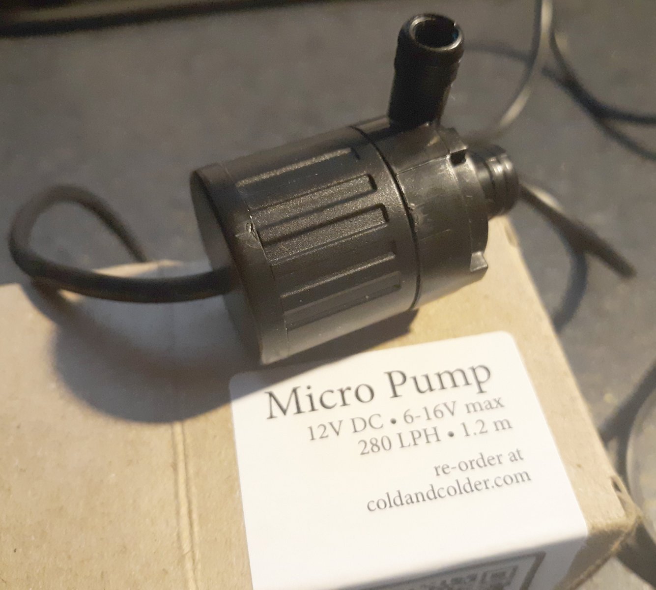
Not a lot going on in my shops for months now, at least, not for me; but I did get some equipment for Pride... The real Pride of Baltimore was a wet boat. It wasn't unusual for her decks to be awash in a seaway, and I figure the model will be no different, maybe more-so. To that end I decided to install a bilge-pump. I searched forums, Facebook, YouTube, and anywhere I could think of to get some idea which pump would be best for the job, and all I really learned was while there's a great deal of information on the Internet, a great deal of that is useless. I finally settled on the little impeller pump pictured, which should fit nicely deep in the model's bilges and pump out any excess. I think I'll also use the electronics set-up in the next pic provided by Dan Lewandowski over on the RCGroups forums a few years back.


- 79 replies
-
- 2
-
-
- pride of baltimore
- privateer
- (and 3 more)
-
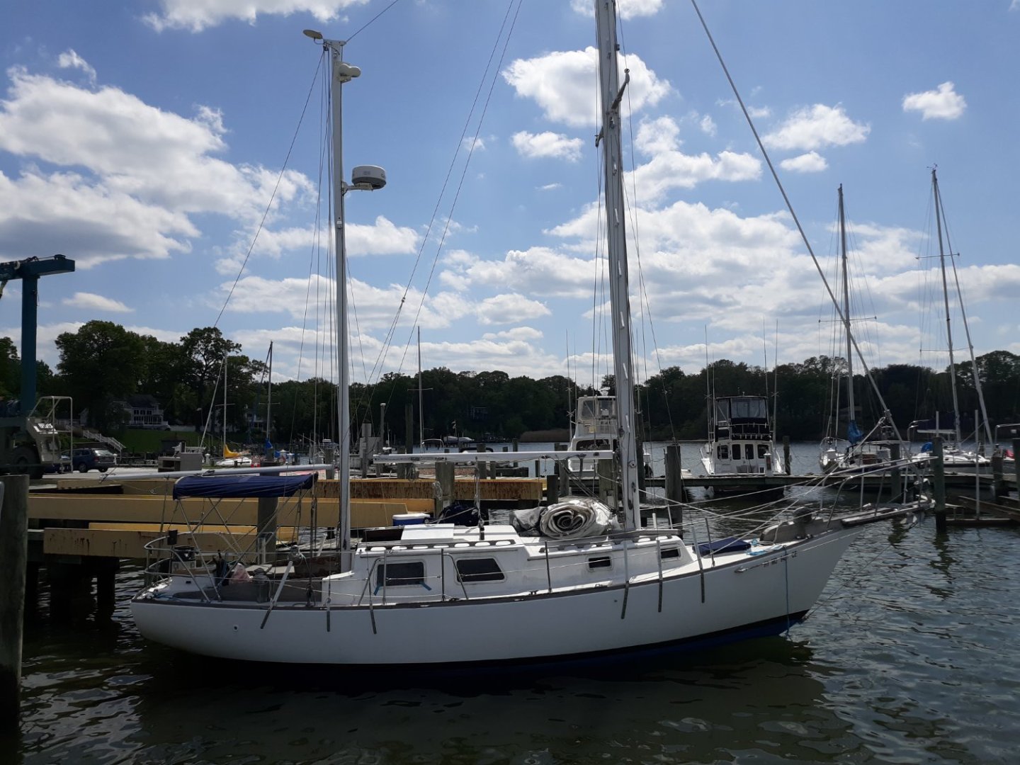
I've been very busy and haven't done much of anything to any of my models. I managed to do a lot for a lot of other people, and not much for myself (hobby wise). I am officially retired since Frebruary, but don't be fooled into thinking that means you'll have more time for yourself, it seems it means just the opposite. Anyway, a friend got a Mariner 31ketch named Ashlinka, that needed some work, and I've been helping with that. We're about to replace the bowsprit with a new made one, and after that, what's left to do is pretty much cosmetic. I've still been searching for left-handed taps and dies, or even steel screw and nuts, to make the rigging-screws mentioned a while back, with no luck; so I've decided to make them "non-functional" and maybe even 3D print them. If that works out, I can get to some serious rigging. The ketch above is normally kept at a private dock on a creek just off the Chesapeake Bay near Baltimore, which is a great place to take Constellation and Pride of Baltimore out sailing.
- 553 replies
-
- 4
-
-
- sloop of war
- constellation
- (and 3 more)
-
The binnacle is placed forward of the wheel so the fellows standing at the wheel can see it. He/they stand aft of the wheel, beside the drum, and look over the wheel, down onto the binnacle. I did find the title "armed privateer" a little odd, as it implies the existence of "unarmed privateers" The Grecian is a very nice subject for a model, not only as a Baltimore Clipper schooner, but for that humpty-dumpty rail.
- 80 replies
-
- 5
-
-
- Grecian
- Vanguard Models
- (and 3 more)
-
The jackstays on Constitution are iron, I doubt anyone served iron fittings.
-
Crows-feet faded out of style around 1800 or so. The tops were structured differently so they didn't require them any more. Quarter-boat davits were also coming into vogue around that time. Basic hinged straight posts at first, and getting more curved, or "davit" shaped" by the end of the first decade. By 1805 I doubt any of Nelson's ships had crows feet, and most had quarter-boat davits. Do you have access to the "Masting & Rigging of English Ships of War 1625-1860" It's an expensive book, but it's an invaluable source of information.
-
How Realistic Can One Make Sails?
JerryTodd replied to Julie Mo's topic in Masting, rigging and sails
The thing that ruins model sails for me is the insistence that seams be stitched, because at the usual model scales, the stitching amounts to being cable as big as a man's arm and just looks cartoonish. When you look at photos of sails, what you see and interpret as "seams" are shadows - not stitches.