

AON
-
Posts
2,574 -
Joined
-
Last visited
Content Type
Profiles
Forums
Gallery
Events
Everything posted by AON
-
 My official last post for 2023! The last pieces to make were the sliding foot assemblies that allow the tiller rope to pass through the deck on both sides of the rope barrel while keeping water from passing through to the deck below. I envisioned making these two assemblies in pieces but after completing a scaled drawing I realised it would be much too small for my limited talent. I made a base plate to represent the quarter round trim work, and carved a single block to make the lower housing and the sliding shoe pieces. As these pieces on my model are fixed my rudder will not turn. I used a #66 drill to make the 2" diameter rope hole through it and dabbed some metallic copper paint around the holes to represent the copper trim work. Both assemblies are identical. When mounted, one is rotated 180°. As the ship's real wheel was rotated the drop of the seven wraps of rope around the hub or barrel would shift forward and aft. The real Tee shaped shoe would slide in the fixed housing Tee slots to accommodate the shift as the rope passes through a slotted hole the deck. Next I decided it was also time to consider adding the five sets of fixed blocks to the frames and I needed to research and draw these at my build scale. First I needed to understand what ropes passed through them so I would know their sizes and be able to determine the sheave diameters and other dimensions associated with them. They were identified as: 1. The main yard braces (4-1/2" circumference). This is a double sheave at the stern quarter on the poop deck level, just above the planksheer. The forward end of these sheaves tilts upwards between 6° and 10°. I split the difference and drew mine at 8°. This seems to be a filler block of wood between timbers and behind a face plate or plank. I will not be installing this one so soon as there is no cutting into the framing timbers required and they are located quite high in the build. 2. The main sheets (7-1/2" circumference).This is a single sheave at station 22 across from the mizzen mast at the upper deck level. The forward end of this sheave tilts upwards 8°. This is a filler block fit into a rectangular opening from the inboard side of the ship. The inside face of the block has ears or tabs at both sides that rest against and are bolted to the timbers. David Antscherl had an excellent sketch in both his book series: The Fully Framed Model and also in the NRJ Spring 2012 issue 57-1, Shop Notes (pg 45). 3. The foresail sheets (7" circumference). This is a single sheave at station (1) forward of the main mast mast at the upper deck level. The forward end of this sheave tilts upwards 8°. This block is similar to item 2 above. 4. The mainsail tacks (9-1/2" circumference). This is a single sheave at station G-forward, across from the belfry but on the upper deck level. The aft end of this sheave tilts upwards 8°. This block is similar to both items 2 and 3 above. 5. The cat fall snatch blocks (5-1/2" circumference). This is a single sheave located between the planksheer and fife rail, above the cat tail at the forecastle deck level at station Y. This sheave is level to the planksheer and deck. I will likely not be installing this one so soon for the same reasons listed for not doing the main yard brace fixed blocks (item 1 above). I used Steels' rigging tables found in Volume 1 of The Elements and Practice of Rigging and Seamanship to determine the line sizes and both Rees' and Steels' block sizing calculations to determine the sheave diameters and thickness. I listed these earlier in my build. So, my list of items to do next grows.
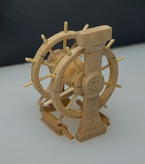
-
I've spent the last two days researching what lines went through the chesstrees on the ship's hull. You've last group of photos showed me. Thank you!
- 364 replies
-
- 1
-

-
- bellerophon
- victory models
- (and 2 more)
-
Thank you! That looks like it was made for just that purpose. How could you get so lucky?!?
-
That looks really good. Could you please post a closer view of one.
-
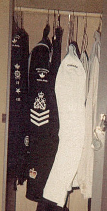
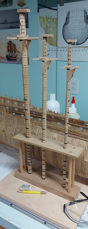
...and the pedestals are done. I left a wee bit extra material at the foot and more again at the head so it can be adjusted to fit the space when the time comes. All is stored away at the moment. As I might not post again until the new year I would like to thank all those that have been following, visiting occasionally, and offering encouragement. Wishing all a very Merry Christmas and a most enjoyable New Years!
-
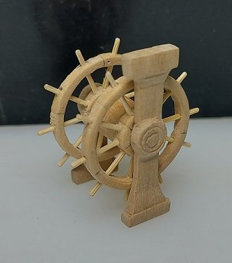
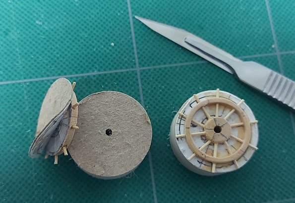
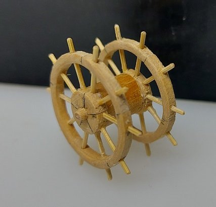
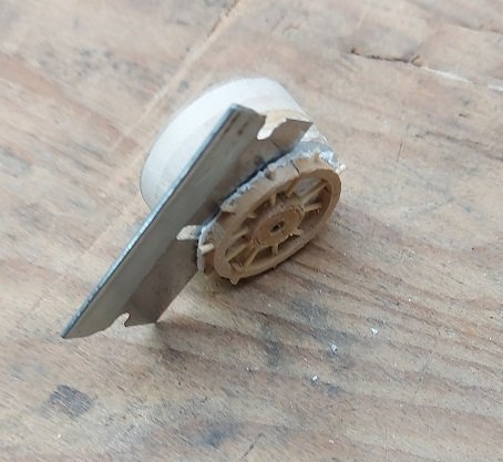
Third try was the charm - first photo peeling it apart - second photo dry fitted to axle - third photo glued up Presently working on my second attempt at the pedestals
-
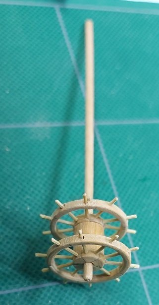
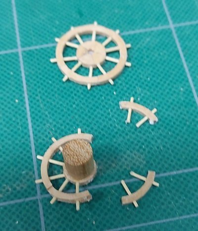
Third set almost completed. Bamboo spokes dry fitted (not glued in yet). Below them is the dowel for the axle it will spin on. Below that is the left over spoke material. I will complete these tomorrow and possibly the pedestals... then see what it all looks like from a distance.
-
Also started the pedestals for the wheel assembly. See how she looks and may toss it when done and try again. The more you do the better you hope to get at it.
-
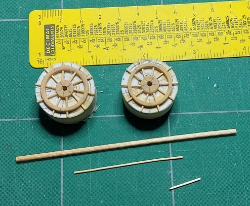
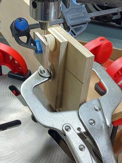
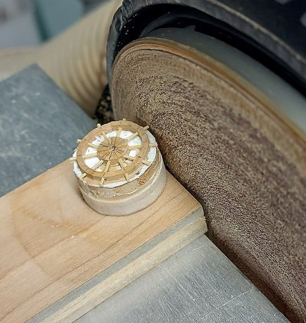
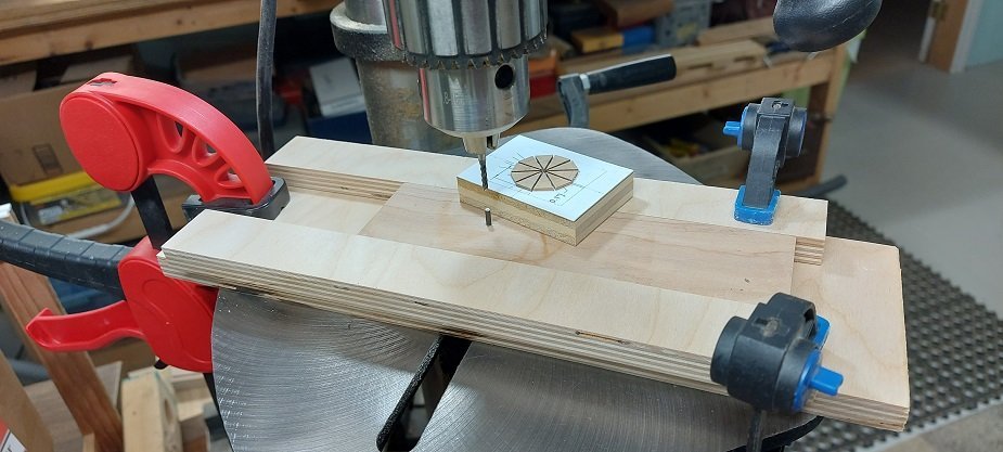
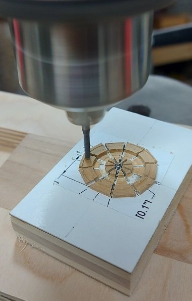
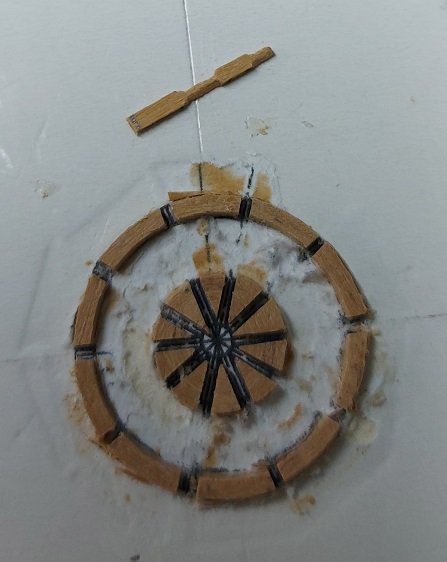
Chucked out my second set of ship's wheels. Due to my reduced scale of 1:64 the thickness would be 0.06". After my first attempt I decided this was a bit too thin for my talents. I increased it to 0.09". My spokes are 0.03" diameter. I tried to turn and shape these chucked into my Dremel and using files but it is just too tiny for me. I decided to follow the KISS principal and used bamboo sized through a draw plate. I built a rotary device so I could drill the holes to slide the spokes through the outer ring and into the inner/central hub. The tiny drill bit went a wee bit askew and the spokes did not pass through to the hub evenly spaced on the inside. Looked great on the outside. I had made my spokes a little longer than required. I mounted my rotary device on my sander and sanded the spokes down to the correct extension length outboard of the outer ring... spinning it from spoke to spoke. I was gluing the rope barrel to the second wheel when the outer ring glued joint broke at one spot. Tried to fix this and dropped it. Broke into a few more parts. I decided this was a sign to toss it and do it again. Sanded a new bunch of wedges to 0.08" instead of 0.09. A tiny change but a wee bit closer to 0.06". Lets see if the third time is the charm with everything else I learnt.
-
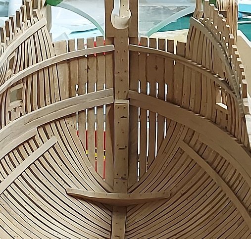
Made and fitted the lowest breasthook to the stempost/bow. Started with fitting a cardboard template. Traced that onto my blank and cut it on the scroll saw. Fitted again then sanded the bevel. Dry fitted in photo below.
-
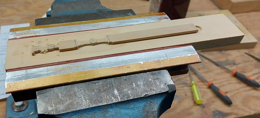
All three lower masts are assembled less their woolding ropes. I don't know why but the mizzen was a beast to complete. They are presently stored in their stand in a box safely out of my shop. I decided to try to make a ship's wheel. Three attempts so far. All failed, but I learnt quite a bit. Refined my setup. I have a sliding top in a fixed base. My template is rubber cement glued to a thicker card that is rubber cemented to a rotating table (block of wood on a metal pin). I bevelled all the under edges of the rotating top and waxed the moving bits. The wood was PVA glued to the template. The rotating top was centred under the cutter and all was clamped in position. The sliding top was moved so the cutter was located properly, then lowered to touch, the top was rotated slowly and the cutter was lowered to remove a thin slice, then repeated. This worked well the last time. It was the wheel spokes the did me in this time. I didn't like them at all. I am rethinking that step.
-
Darn good start. Mine took multiple starts, stops, starts, scrap, repeat. It isn`t museum grade but I`m happy-ish with it. Seeing what you`ve done so far with your carvings has me wishing you might make me a new figurehead. But we will wait till you`ve done before it comes to that.
-
I'll make a note of that. Thanks
-
Lord knows they had lots of tar.
-
I don't think the canvas back in the day was painted. I could be wrong. I plan to use light khaki coloured paper, like the kind used for packing by Amazon. Dry fit and trim. Glue on one surface with white PVA so it dries clear and wrap it around with the seam facing aft. If you like add pencil dots to simulate nail heads the next day, after everything is completely dry. Should look gorgeous. If not, dabs of water will help soften the glue to remove it.
-
Started my third lower mizzen mast yesterday after having scrapped the first two. They will be used for something later... possibly a yard? I don't know why this mast is giving me trouble. As the diameter of this one is too small for my lathe support I have shaped it following David Antscherl's description in Volume IV pages 15-18 of The Fully Framed Model. Getting the initial tapered shape wasn't where I screwed up. It was the flat for the cheeks. I managed to get them correct yesterday. Going to work on the cheeks and trees this afternoon. I have conflicting information on this lower mast with regards to having or not having a front fish. Only one reference wants it to have the front fish. For it's size it is a made mast but without a spindle, and it will have no front fish. Once again I simplified this one by shaping one 3/8" thick square piece, knocking the four corners off and sanding round and slightly tapered. Due to the size I think I will simplify the cap tenon by offsetting a straight square. A photo will be posted when done.
-
This photo is from early yesterday with woolding hoops and metal hoops installed. All bolts have since been installed in the mast and the trees are assembled and installed. Today I finish installing the bolts and leather gasket on the mast cap. Then I move on to the Mizzen lower mast.
-
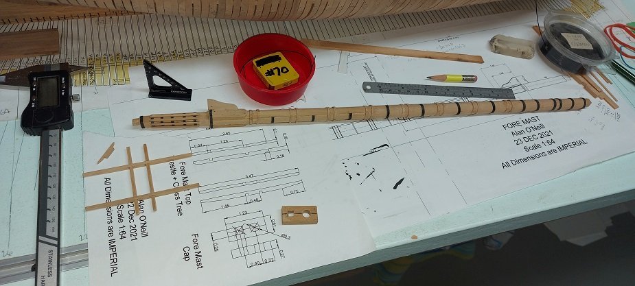
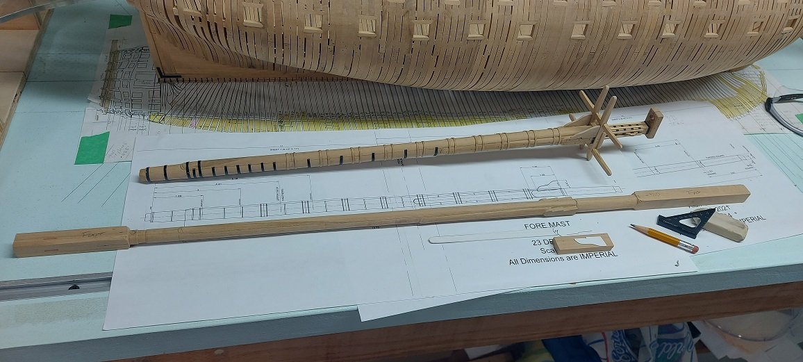
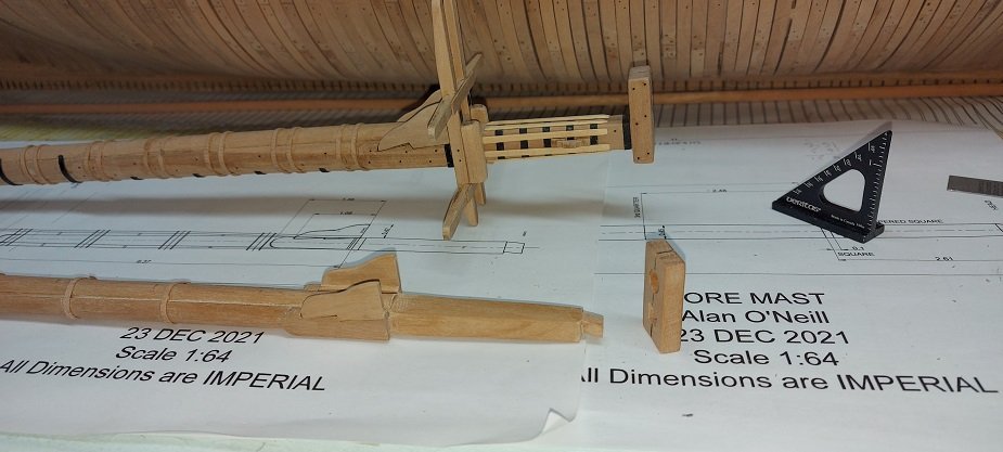
I started my second lower mast, intending it to be the mizzen but my steady only goes down to 1/2" diameter so I turned the foremast instead. I may have mentioned it is a made mast and rather then go to all the trouble I did with the lower made main mast, I decided to simplify this one. The centre is one piece instead of two. The front fish is an add on reaching down to almost the foot as it should for the time period. The side cheeks are added pieces as are the bibs. I made the mast cap and talked myself out of simplifying the angled square mast head tenon that fits into the cap. I thought of making it a straight square piece as no one will see it but me... but then I cheated on everything else. So in the first photo below you see my completed lower made main mast in the back ground. The lower foremast is in the fore ground with the front fish and side cheeks added. I hadn't removed the square stock extensions at the foot and head yet. The stock for the bibs, two pieces rubber cemented together, has the card template on it, ready to mark off and cut two at once. The next photo below shows the mast cap and the angled square mast head tenon that fits into it. The bibs are attached and upper woolding hoops have been installed. Later this week I will install the lower woolding hoops. This were made from Costello wood shavings as was done on the main mast. That is all for now.
-
Thanks. The steady is from Lee Valley Tools. It is quite solid with three wheels (one below and two above) and took a couple tries to figure out it was a simple scissors adjustment. Now moving it about and resetting it is quick and easy.
-
In this instance for the length and diameter of the part, three times.
-
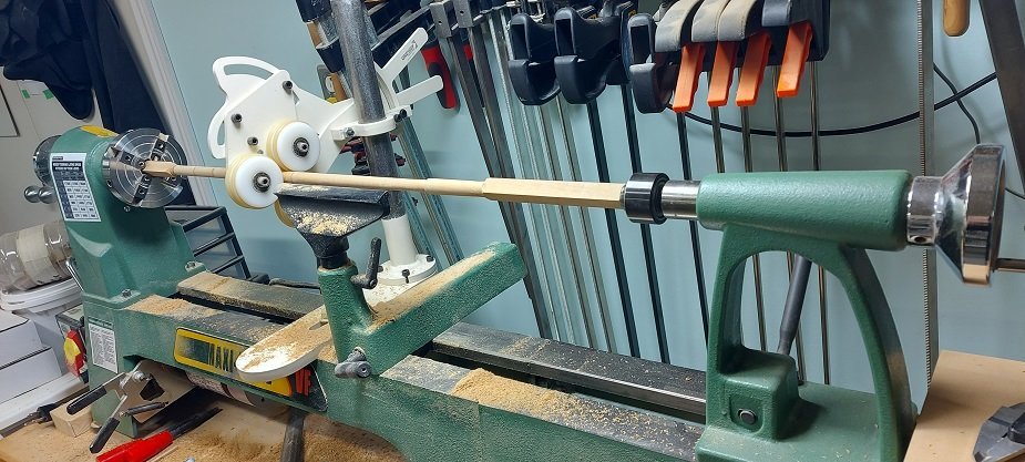
I had a busy September; getting things ready for fall and winter, and my son's wedding. I reworked the one carving (of the two) I had done for my kayak model for scale after having attended the NRG modelling realistic water workshop. I think this link will take you there to see the before and after of it: I have installed all the deck clamps I care to, including the orlop deck, and am presently turning my lower mizzen mast. As it is not a made mast it will be a bit easier. The shot below includes the "steady" Druxey asked about quite some time ago. I did a rough major diameter turn. Marked off the upper and lower quarters and presently have the top tapered. Going to work on the lower half Tuesday. Expecting company tomorrow (Canadian Thanksgiving Day). Once I have this and the lower foremast made I will install the three mast steps and then the deck beams.
-
Welcome aboard. You'll not find a better forum or helpful group of people than here at the MSW. I sent you a PM (private message).
-
Prior to mid 1800's port was referred to as larboard.
- 479 replies
-
- 2
-
-
- vanguard models
- alert
- (and 1 more)
-
I think she's water tight now!
-
Yup, sailors have been using both common whipping and sailmaker's whipping for centuries. Two quite different whipping methods. The former is quick and can slip off the end of a wet line, the latter is long lasting, so much so that it was used on the end of reef lines, two sailmaker's whippings in series. When the end of the rope wore down past the first whipping of the two in series due to it slapping against the sail the second took over until the sailmaker could take the sail down and change them all out again.
- 479 replies
-
- 3
-
-
- vanguard models
- alert
- (and 1 more)

