


AON
-
Posts
2,878 -
Joined
-
Last visited
Content Type
Profiles
Forums
Gallery
Events
Posts posted by AON
-
-
-
-
Final updates.
My third bowsprit and first jib boom.
-
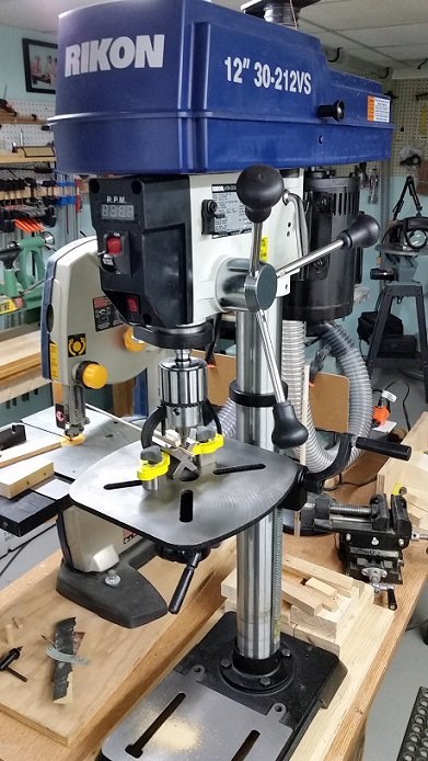
Last weekend I went to Lee Valley Tools to pick up some clamps for the dust collection hoses. They had this drill press that caught my eye.
I went over and grabbed the chuck and gave it a wiggle. The damn thing didn't move! After talking to the floor guy I brought it home.
See my cheap Canadian Tire drill press wandered all over the place. The store clerk at Art's Tools (where I normally shop) told me you cannot get a decent drill press that doesn't wander anymore for a reasonable price. Only industrial grade ($$$$) have that.
Well my new drill press does it. As a bonus it handles small number drills. The chuck sizes reads 0.8 to 16 mm (0.03 to 0.63 inch). Well I have had a #76 drill bit (0.02 inch or 0.53 mm) in it and no wiggle!
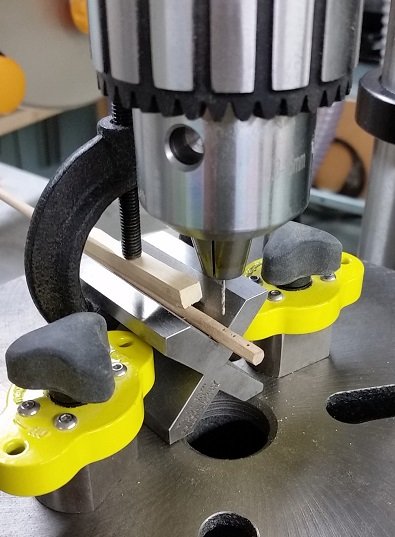
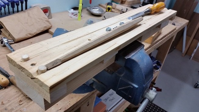
Below is the heel of my Jib boom being drilled.
- paulsutcliffe, Canute, mtaylor and 6 others
-
 9
9
-
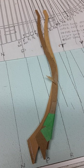
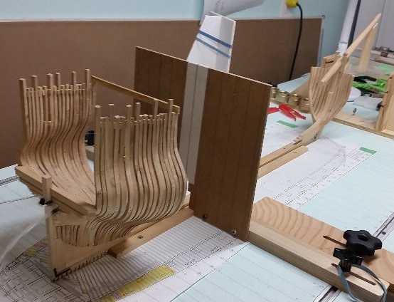
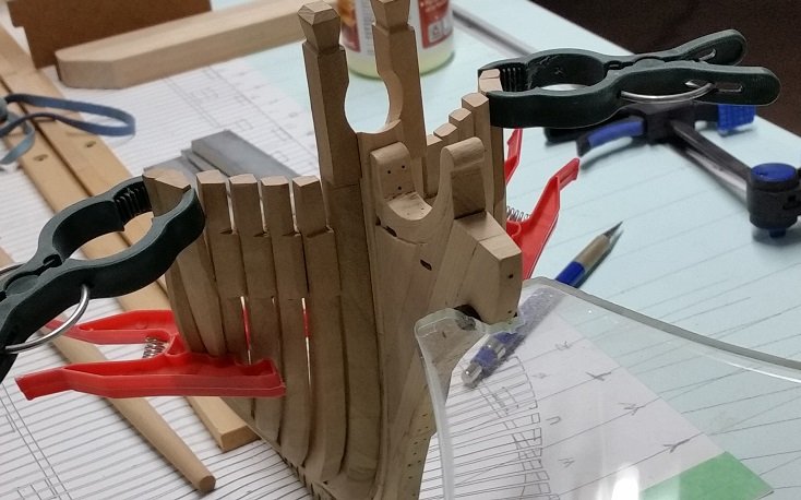
Also I was having a problem with my forward cant frame installation.
I had to remove everything I hand done forward of the hawse pieces. As I wasn't happy with how this was going (dragging my butt on this) the amount of work required was minimal.
The frames installed well to the forward deadwood but protruded far beyond the plan laid out below it on the table.
After considerable head scratching I made a cardboard template of the frame, cut it in two pieces and overlapping the pieces to fit the plan properly I taped them together. This revealed how much they were too long. I then had to figure out why!
Went back to my 3D model and after some time discovered I had not allowed enough opening between the frames for the deadwood.
So I am presently sanding the frames shorter and reinstalling them.
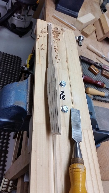
In the photo below you can see the template and the mark on the frame indicating what needs to be removed.
- BANYAN, GrandpaPhil, Canute and 5 others
-
8
-
Having been busy with a number of things I think it is time for an update.
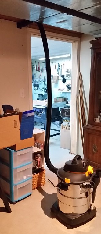
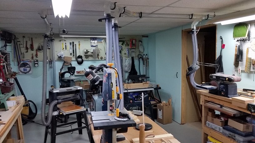
First: an addition to my shop. I've added a dust collection system. The new more powerful vacuum is outside the shop to reduce the noise level inside (I can slide the barn style door closed).
The hoses drop to a number of work stations and it picks up more than 90% of the mess I make!
I just have to remember to turn it on and open the proper valve!
-
Good morning Mark,
I had a quick review and find it to be bit difficult to read the fractions in the table of image 033 but I think it reads that the Fore-Top-Mast-Stay is 8-1/2 inch circumference ( = 2.7 inch diameter) and the Preventer Stay is 6-1/2 inch circumference ( = 2.07 inch diameter).
I see I made an error. The Top Mast Stay is Half the size of the lower stay which makes it 8.33 inch circumference or 2.65 inch diameter).
The topmast preventer stay is 3/4 of this which is the 6.25 inch circumference or 1.988 or 2 inch diameter.
Thank you.
- Canute, paulsutcliffe and mtaylor
-
3
-
Thank you for the link Mark
I'd not been aware of these tables before.
Very interesting. I will check how my other lines compare later... back down to the shop now!
- paulsutcliffe, mtaylor and Canute
-
3
-
While I move ahead with my forward cant frames and the tree nailing of my aft cant frames to the deadwood, I want to complete my bowsprit. As I had made a number of rookie errors I thought I'd best get both my sketching and math down clearly on paper. I've made two bowsprits to date. The first was a quickly turned cigar shape on the lathe at proper dimensions to simply see the fit in the bollard clearance hole and determine my satisfaction with the diameter (posted earlier). The second was properly shaped on an Ed Tosti style board as he'd shown on his Young American build. This last one is not quite right so I will do it again. Practise makes perfect... or nearly so!
To start with I must say I snagged a copy of an excel document entitled Masts and Rigging from somewhere. I believe it was this forum. I checked the properties and the author was Danny Vadas. I've found it to be a very helpful tool to cross check with. As I cannot see the formulae controlling the results in the cells I need to verify the numbers as best I can. The following explains the process. I am new to this so it also serves as my reference for later on as I will do more of this. I also snagged a copy of another excel document entitled Steels Dimensions by Y. Miroshnikov which is equally as useful.
I must say that I found The Fully Framed Model Vol. IV by David Antscherl to have been very helpful because of the photos, plans and descriptions. The same can be said for Rigging Period Ship Models by Lennarth Petersson. They helped me understand what I was looking at or searching for.
The following detailed explanation is quite long. I hope you do not mind, but I find the process fascinating.
BOWSPRIT with CAPS, BEES and BEE BLOCKS
As mentioned earlier I used REES's Naval Architecture (1819-1820), page 106, plate VIII for the dimensions, however he does not give much information regarding the Bee's and the Cap. I had looked at The Anatomy of Nelson's Ships (figure 116, page 185) but something wasn't quite right between this and some Vanguard kit builds I've been following. I needed to look deeper.
Key dates: HMS Bellerophon was ordered in 1782, launched in 1786 and completed in 1787. This immediately suggests Rees might be a poor choice due to its date of 1819-20.
I went to The Masting and Rigging of English Ships of War 1625-1860 by James Lee.
All the information required is in Section 1. Mr. Lee agrees with Mr. Rees with regards to the ratio of the tapers of the bowsprit, but length and diameter differ in Appendix I ( Length = 0.6 x the length of the main mast = 104.25 x 0.6 = = 62.55 feet versus 64 feet; diameter = 62.55/3 x 1.555 = 32.3 inches versus 36 inches). Appendix II of Lee's reads HMS Valiant 74 gun 3rd rate Bowsprit was 36" diameter x 69'-5" long.
Due to the scale of my build (1:64) a difference of 3.7 inches (at scale = 0.06") diameter is not at all noticeable, and 1.45 feet (at scale = 0.27") difference in length is arguable. As REES shows details I will follow his plate VIII as best I can.
Mr. Lee suggests that looking down at the Bees they were somewhat scalloped fore and aft for the time period of my build.
The Bees were 2-1/4 times the diameter of the bowsprit at this location (2.25 x 20 = 45 inches long); their breadth would be 2/3rds the diameter (2/3 x 20 = 13.3 inches wide); their thickness inside was 1/4 the diameter (1/4 x 20 = 5 inches thick at the bowsprit) and tapered to 4/5ths the thickness to the outside (4/5 x 5 = 4" thick outboard). The outboard edge tilted upwards by the thickness of the inner edge plus 1 inch. This would be 6 inches. This is all different than what was shown in The Anatomy of Nelson's Ships.
I will be following Mr. Lee for the Bee's and Bee Blocks.
Below the Bees are the Bee Blocks. They were 7/9 times the length of the Bees (45 x 7/9 = 35 inches long). They were half the width (13.3 / 2 = 6.65" wide) and 2 inches per foot of length in depth ( [35 / 12] x 2 = 5.83 inches deep).
There were two holes in each Bee at one for each of the the foretop stay and the foretop preventer stay and one spare per side. These holes were elongated slightly fore and aft to better receive the stays as they passed through the Bees and Blocks. There were no sheaves at this time.
What size hole do I need in the Bee for the Stay to pass through?
If I know the size of the rope I can determine the hole size needed to clear.
I went back to The Masting and Rigging of English Ships of War 1625-1860.
In Appendix I it explains that the sizes of fore topmast stay and the fore topmast preventer stay are calculated to be a proportion of other considerations....
The topmast stay is 1/2 the size of the lower stay.
The lower stay is 1/2 the diameter of the lower mast.
The fore topmast preventer stay was 3/4 the size of the topmast stay.
The foremast was the same proportions as the main mast.
The main mast diameter from 1773 to 1794 was 9/10 inch per 3 feet of length.
How long was it?
In my time period the main mast length was 2.23 times the ships beam.
The ships beam per the contract was to be 46 feet 9 inches (561 inches).
561 x 2.23 = 1251.03 inches (104.25 feet).
The main mast diameter would be 104.25/3 = 34.75 x 9/10 = 31.3 inches diameter.
The foremast would have been the same diameter.
Now things start to not make sense to this novice.
If the lower stay (rope) is half the diameter of the lower mast it would be 15.65 inches diameter!
I think he meant size of rope which was the circumference not the diameter!
The diameter is the circumference divided by Pi (3.1416).
15.65/3.1416 = 5.3" diameter rope.
The top mast stay is half this 5.3 x 1/2 = 2.65 inch diameter (or 8.33 inch rope by circumference = 2.65 inch diameter)
The topmast preventer stay is three quarters this or 2.65 x 3/4 = 1.98 or simply 2 inch diameter.
I will make the holes 3" diameter (at 1:64 scale is 0.05" diameter = #55 drill bit).
Since I'm all warmed up I may as well carry on with the Jib Boom details and get it over with.
JIB BOOM
I took the dimensions for my Jib Boom directly from REES's Plate VIII. The major diameter is 11" and the overall length is 51'-0". Only the heel end is octagonal in shape for a distance of 4'-4". The length differs from what is described in The Masting and Rigging of English Ships of War 1625-1860. Mr. Lee directs the length of the hex shape at the heel to be 3.5 times the diameter (3.5 x 11 = 38.5 inches). Mr. Lee also directs the length of the Jib Boom to be 0.41 x the length of the main mast (0.41 x 104.25 = 42.7 feet). This is a difference of 8.3 feet (1.5" at 1:64 scale). The diameter is to be 7/8 inch per 3 feet of length or 12.5 inches.
Mr. Lee also gives some drawing details for the Heel Lashing Hole and Heel Rope Sheave. The slot in the Jib Boom for the Heel Lashing Rope Sleeve (sheave) is horizontal and the length of the slot is 1-1/16 x the diameter of the Jib Boom (1.0625 x 11 = 11.7 inches). The slot is located a distance of 1.5 times the diameter from the heel of the Jib Boom (1.5 x 11 = 16.5 inches whereas Mr. Rees locates this at 2 feet). The Heel Lashing Hole runs horizontally and is halfway between the Jib Boom heel and the slot for the sheave (8.25 inches).
There is another sheave located at the head of the Jib Boom for the Jib Outhauler. This sheave runs up and down (vertically). Mr. Lee directs it to be located "a few inches abaft the rigging stop". For my time period the rigging stop was tapered back to a shoulder.
Mr. Rees shows the horizontal heel sheave slot to be 18" long x 4 or 5" wide. The outhaul couldn't possibly be the same size as the head of the jib boom is so much smaller in diameter than the heel (7.3" versus 11"). In my novice opinion there seems not enough "meat" left either side in the boom to support it. To double check this I need to know the size of the Heel Lashing and Jib Outhauler ropes which will determine the sheave sizes.
Mr. Lee directs that the Heel Lashing is the same size as the Bowsprit Shroud Lanyard which were the same size as the Gammoning which were 0.44 of the Forestay. The Lower Stays are 1/2 the diameter of the lower mast. The lower mast was the same proportions as the main mast... 9/10ths inch per 3 feet of length of the fore mast, which was 0.93 x the length of the main mast which I'd already determined to be 104.25 feet.
104.25 x 0.93 / 3 x 9/10 x 0.5 x 0.44 = 6.4 inches circumference / 3.1416 = 2 inches diameter rope.
From Steels I find the sheave diameter is 5x the thickness of the sheave but in Lee's it is 4x; the sheave thickness is 1/10th more than the rope diameter; the breadth of the sheave hole is 1/16 inch greater than the sheave thickness; the length of the sheave hole is the sheave diameter plus one rope diameter in Steels whereas in Lee's it is 1-1/3 x the sheave diameter.
A sheave for a 2 inch diameter rope would be 2.1 inches thick x 10.5 (Steels) or 8.4" (Lee's) inches diameter. The sheave slot would be 2.163 inches x 12.5 or 11 inches.
For the Jib Heel Lashing on my drawing I find a 10.5 inch diameter sheave does not suit my 9.5" across flats hex shaped heel of the jib boom. I made my Heel Lashing Sheave 8.4" diameter and the hole 2.2" x 11".
Search as I might I cannot seem to identify the rope size ratio for the Jib Outhauler. The Mast and Rigging spread sheet (which has proven to be reasonably accurate up to now) suggests the Spritsail Yard Halliard and Running Lifts and the Fore Trisail Outhauler are all 1" diameter. As these are all in the same general area it seems reasonable for the Jib Sail to be similar.
The sheave for a 1" diameter rope would be 1.1 inches thick x 5.5 or 4.4 inches diameter. The hole would be 1.163 inches wide x 6.5 or 5.7 inches long. Again the differences are those between Messrs. Lee and Rees.
I will use the 5.5 inch diameter sheave and the 1.1 inch wide x 6.5 inch long slot for the Jib Outhauler.
This fits nicely in my drawing. PDF attached!
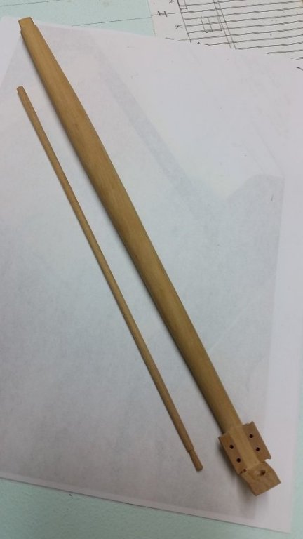
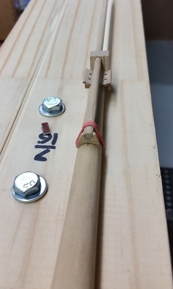
Also a couple pictures from my second Bowsprit.
****
This exercise took a number hours over just as many days. I needed to walk away and shake my head clear a few times, review a number of books and re-read passages many times. This is the kind of stuff that cranks me up and gets me jumping for more!
Yes I really enjoyed it that much.

- tlevine, Canute, KARAVOKIRIS and 10 others
-
13
-
-
Also, I made a quick bowsprit at about 37+ inches diameter (Ree's says it is 36" diameter) to see how it would look.
I am not happy with the gap and so will make it a little larger.
No one will be taking a caliper to it!
Then I researched the finished shape of the cap end of the bowsprit to accept the BEES and made notes.
I'll be making a good bowsprit soon enough to have a change of pace... after all they say a change is as good as a raise!
- Mike Y, oneslim, KARAVOKIRIS and 9 others
-
12
-
Hope everyone is having a great St. Patrick's Day!

I completed the installation of the hawse pieces moments ago.
Also completed the installation of the chocks at the head of the aft cant frames.
Time to start on the forward cant frames... not today though.. because my name is Uá Niáll and it's St.Patrick's Day!
-
-
Okay... I admit I have never cast anything for models. Industrially we used sand. Yes it was a special casting resin but it had no "give". It was solid.
What if you built two boxes. One as a skin for the mould. The other twice as large. Put a couple inches of sand (clean dry beach sand) on the floor of the second. Put your mould in the first box then put the first box centered in the second and on top of the bed of sand. Then pack sand all around the first but inside the second. These could be reused over and over again plus any spillage is on the sand.
Just a thought.
-
Pat
I appreciate your suggestions.
There is always the plan B that I spoke to my wife about at lunch... make the bowsprit a hair larger in diameter.
I will make a test bowsprit to see what it looks like with and without the leather layer.
I have coloured paper to simulate the leather for the test.
Thank you... I learnt something from you today.
-
More of those moments then I care to admit to!
My back is back to normal, thank you for asking. I hope you are back on your feet again.
Only people with this infliction understand how debilitating, aggravating and painful it really is.
Back to this leather capping on the head of the stem post and apron.
Would this have been tarred?
In my searching the only thing I can find was two references where they say the gammoning was covered in leather and tarred to protect it from the water and chaffing.
-
-
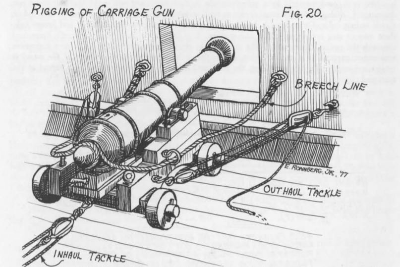
sorry to flog that dead horse ... but I just stumbled upon this
Fair American 1780
18th Century War Brig
Pg 24 figure 20
by Eric A R Ronndeag Jr.
Not certain what keeps it from falling off in rough seas or the heat of battle.
- mtaylor, paulsutcliffe and daHeld73
-
3
-
-
Steven
I thought long and hard on how to respond to your especially kind post.
Thank you! 😊
But as Wayne and Garth said to Alice Cooper... I (feel) am not worthy.
Druxey and Pat
Regarding the leather puddening strip on the head of the stem post. If either of you have a reference such as a picture I'd feel better about how I install it.
I confess I haven't looked yet but will be searching myself today... but first I have an appointment at city hall.
Alan
-
-
I failed to report an error I had made... but caught before damage was done.
While measuring the bowsprit from the plate in Ree's I failed to notice the section views directly above with dimensions! See post #817 above.
These identified the bowsprit to be 36" diameter not the 3'-5" as I had measured with my dividers against the provided scale.
The diameter of my clearance hole is ever so slightly oversized (0.60" versus 0.563").
-
Thank you... but in retrospect, I should have probably just followed Kenny's video. Short of the rotating bollards it is what I ended up doing.
- paulsutcliffe, mtaylor and Canute
-
3
-

HMS Bellerophon 1786 by AON – scale 1:64 – 74-gun 3rd Rate Man of War - Arrogant-Class
in - Build logs for subjects built 1751 - 1800
Posted
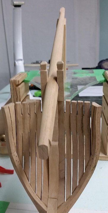
While I am still working on the forward cant frames I went ahead and made the Jack Staff for the Bowsprit Cap.
Full disclosure... I had to make it three times.
From Steels Rigging Tables I find the Jack Staff of the 74 Gun ship was 4-1/2" diameter x 18 feet tall.
From The Anatomy of Nelsons Ship's I find they were tapered (smaller at the top) with a Cap or Truck.
Visiting one of our club members on Wednesday I discovered the cap or truck had two small sheaves in it, one to port and one to starboard, one was a spare. The halyard had to be secured somehow so he figures they must have been something like a cleat near the bottom facing aft.
Looking at TFFM Vol IV I see the cleat on the Jack Shaft.
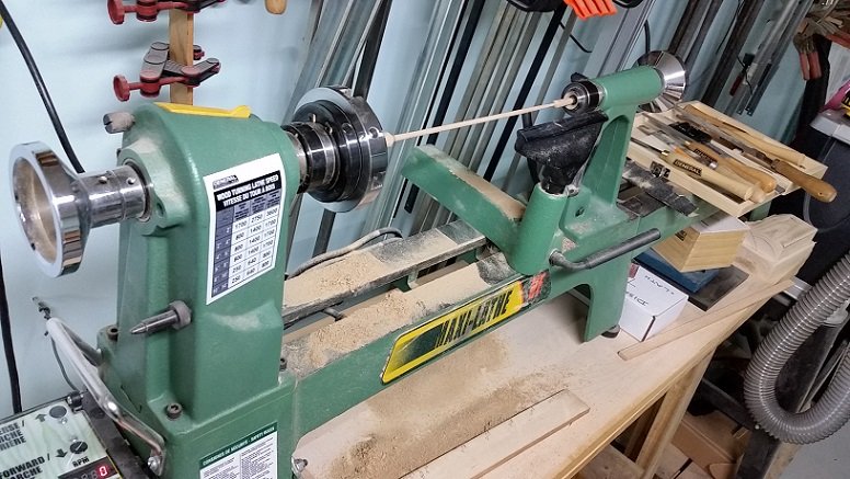
So My Jack Shaft is 4-1/2" diameter (0.07 inch) at the base or heel and 3-1/2" diameter (0.05 inch) at the head or top with an 7-1/2" diameter (0.12 inch) cap or truck. I used 1/8" diameter dowelling, secured it in my drill press chuck and carefully sanded it down to the tapered shape.
When I had the shaft shaped proper I used a tiny saw blade to shape the truck to blend into it.
I will not be cutting in the tiny sheaves as they are just too small.
I have yet to make the cleat.
The Flag (the jack or small version of the full size flag) will be 7'-6" hoist x 15'-0" fly as The Anatomy of Nelson's ships described them as 10 breadths (or 9 inches x 10 = 90 inches or 7'-6") and the size was a ratio 1:2. The Fully Framed Model, Vol IV reads they were sometimes 2:3 or 11:18 with one surviving Jack from Trafalgar measuring 7'-4" x 11'-7". As mine is dated prior to 1801 (when they added Ireland to the Union) there will be one saltire missing from what we recognize today.
Following are pics of my Jack Staff, a union Flag dated prior to 1801 and a scrap from Bellerophon's ensign at Trafalgar. The last shows closeup the open weave of the material. Also one very short video of how I shaped the staff.
I am going to make the Union Jack for this staff next.
shaping jack staff.wlmp