


allanyed
-
Posts
8,149 -
Joined
-
Last visited
Content Type
Profiles
Forums
Gallery
Events
Everything posted by allanyed
-
Welcome to MSW B It would be great if you posted a little intro in the new members forum as well. What model are you building? If you start a build log you could get a lot of helpful suggestions on work arounds and thus get more sleep😀 Allan
-
 Thanks Dean Allan
 -
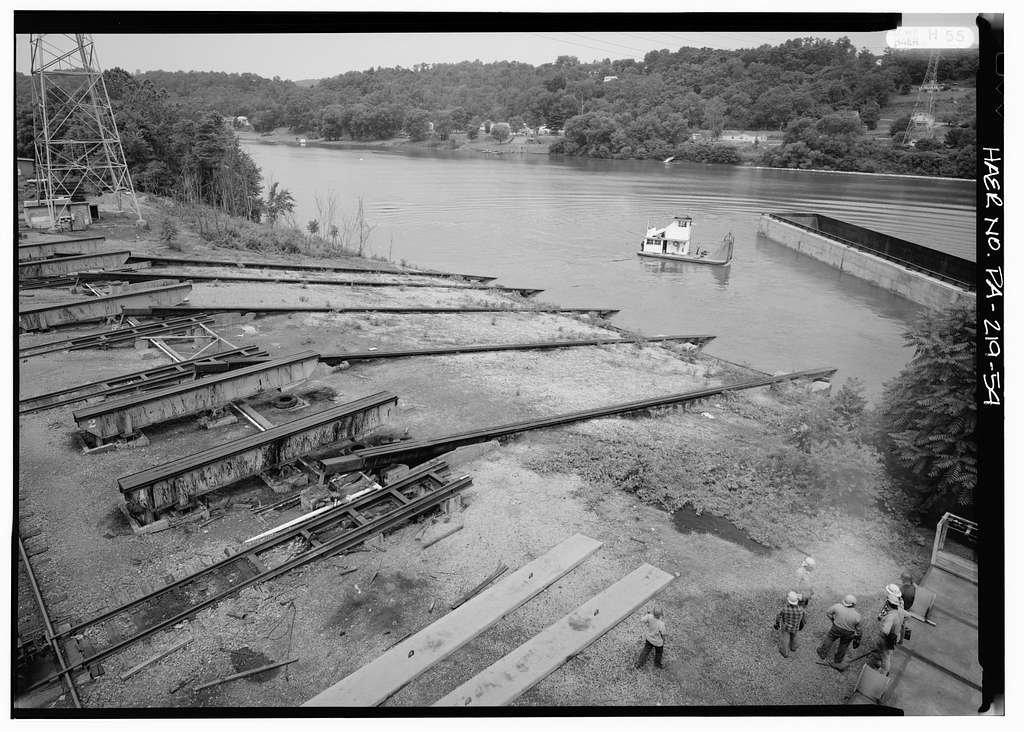
The photo below is the slipways at Hillman Barge and Boat in Brownsville, PA where we had the mishap. This photo was right after a successful launch as the barge and catch boat can be seen on the right. Googling photos of the yard like the one I found below brought back some really nice memories. Allan
-
Welcome to MSW <Canadian> Guy. I hope you enjoy your time here! Allan
-
I worked in two different barge and river boat yards in Pennsylvania and Kentucky and in both we launched everything sideways. We did have one disaster when one of the four restraining systems was not released to allow the vessel to slide down the ramp so it turned and went off the greased rails. What a mess that was. Allan
-
Google Buckler's Hard then go to images. There are a number of photos where you see the slope on the area of the old slipways into the Beaulieu and even the main road through the village slopes down to the river. Allan
-
While not a museum, the New York Yacht Club has a LOT of schooner models that are exquisite. It has been some years so things may have changed but I stopped by and told them about a model I was building and asked if I could visit even though I was not a member. They took me to the room with all the models and left me alone to sketch away. At that time, no photography was allowed, but I suspect with everyone having a cell phone that may have changed. Definitely worth a try if schooners and racing yachts are of interest. I just checked the web and found the following: The New York Yacht Club offers tours of the Model Room at the New York City club house and the exterior grounds of Harbour Court in Newport, RI are open to the public on the last Tuesday of each month, with the exception of August and December in New York, and January, August and December at Harbour Court. Allan
-
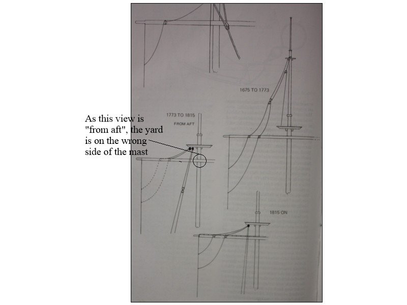
In addition to Phil's post, the leech lines were also run up the front of the sail. I looked at the drawings on page 72 of The Masting and Rigging of English Ships of War by James Lees and there is one drawing that appears to have a mistake. See below. Allan
-
I am always amazed and happy to see the exactness that you put into every part of your builds. Allan
-
Your idea of using a stiffer material is a great idea. I have used my machinist squares similar to your use of right angle acrylic plates. Looking forward to your progress. Allan
-
1848 stage coach concord artrsania Latins
allanyed replied to Paul howe's topic in New member Introductions
Welcome to Model SHIP World JF. Hopefully someone here will be able to give you some help, but this is a ship model group not a stage coach group so you may not get a ton of responses. We do have a forum here at MSW called Non-ship/categorised builds and there are stage coach builds posted there. https://modelshipworld.com/search/?q=stage coach&quick=1&type=forums_topic&nodes=73 You may want to post in the non categorised builds to get more viewers or contact the members that posted the stage coach projects. Hope someone here will be able to help you out. Allan -
HMS VICTORY 1765 by albert - 1/48
allanyed replied to albert's topic in - Build logs for subjects built 1751 - 1800
I was so tired of Victory builds, UNTIL NOW. Just tuned in and catching up. I love that it is the Victory when built in 1765 as it is rarely modeled as she looked then. Allan -
Great piece of information Dafi!!! It took me a little while but I did find this in his Elements and Practice of Rigging and Seamanship, Volume I, page 283, 1794 edition SLINGS have a long and short leg, and a large thimble seized in the bight. The long leg passes round the after-part of the mast, and reeves through the eye in the short leg; it is then brought back, and securely seized to its own part in several places. By these the yard is retained at the mast-head with a laniard, that splices in the thimbles in the slings, at the fore part of the mast and then reeves through the thimble in the strap upon the yard, and so alternately till the laniard is expended. The end then fraps round the turns, and makes fast with two half hitches. In time of action, the yards are slung with chains. Looking at Lees, he conjectures that rope slings came into use about 1773 and the use of chains in time of action appeared about the same time. He goes on to say chain was used at all times as of about 1811. Allan
-
A warm welcome to MSW Brent!! Allan
-
One of the many positive things to me about the thoroughness Chuck puts into his kits is the taper of the knee of the head both fore and aft as well as vertically. This is a pretty basic design item and something seen on virtually all British naval vessels, (and maybe merchant or nations' vessels as well), yet, for whatever reason, the majority of other kit manufacturers seem to ignore this completely. Allan
-
Welcome to MSW Chris. Looks like a nice kit that you have, There is a contemporary drawing of Ontario (16) 1780 at the RMG Collections site you might want to download as a reference. https://www.rmg.co.uk/collections/objects/rmgc-object-84516 After a quick look the kit plans seem to be very good. Thanks for sharing your build. Allan
-
I was surprised and liked very much that the tops of the bulkheads were removed so the moulded dimension of the bulwark is realistic. Was this part of the kit instructions? Hope to see more progress in your build.😀 Allan
-
Keep in mind the 1794 edition is about masting and rigging, nothing about the structure of the hull. The Sim Comfort print of Steel's Elements and Practice of Naval Architecture, if you can find one, goes for about $1000. You can find all the scantlings from the 1719-1750 Establishments, The Shipbuilders Repository 1788 and Steel's Elements and Practice of Naval Architecture in one book from Seawatch books. If the era Steel covers is your only interest The Elements and Practice of Naval Architecture, including the scantlings, are free to download https://www.google.com/books/edition/The_Elements_and_Practice_of_Naval_Archi/TWsmw-QqvmAC?hl=en&gbpv=1 Once you download it, scroll down to page 496 to get to the principal dimension folios. Keep in mind this is for British ships, but lacking better information on US ships, these should be close. This download was mentioned in a post here at MSW in 2017. Allan
-
Looking forward to your build Rick. You surely picked the number one kit maker for our hobby, bar none. One of the best things about the Syren model kits is that Chuck thoroughly researches each offering, confers with experts in ship modeling, then builds the model so he can work out any small issues before going into big production. Allan
-
Welcome to MSW Ralf, we hope you have a wonderful time here. Allan
-
Blocks: wood, card or 3D resin?
allanyed replied to georgeband's topic in Masting, rigging and sails
If you put them in a block/rock tumbler for part 6 it really helps to get a more rounded shape and easier than getting sanding by hand.. Allan -
Fantastic idea Giampiero! We are scheduled to be in in Italy the first week of September, 2025 so I will be in contact with Tiziano and you this time next year. Ciao Allan
-
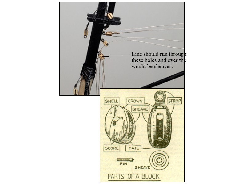
Truly a lovely build for a first go! One thing for the future or maybe you could change now --in your photos the blocks appear to be upside down. The line would go over the sheave and under the crown, not under the sheave and over the tail. The below is from another build, but shows what I mean. Allan
-
Bending hard brass.
allanyed replied to navarcus's topic in Metal Work, Soldering and Metal Fittings
Hi Navarcus Memory may not serve here, but from what I do recall from my marine engineering courses the type of engine had nothing to do with the diameter of the propellors. I sailed on steam ships as well as diesel propulsion with prop diameters up to about 19 feet. The azipods found on today's ships are upwards of 20 feet in diameter as well. There is a practical limit on the diameter no matter the type of propulsion which is possibly one of the reasons larger ships have multiple props. Allan -
Derick Better to PM email addresses than post them here unless you enjoy spam. You can edit your post and remove it then forward it to Jon via PM. Allan


