Search the Community
Showing results for tags 'Model Shipways'.
-
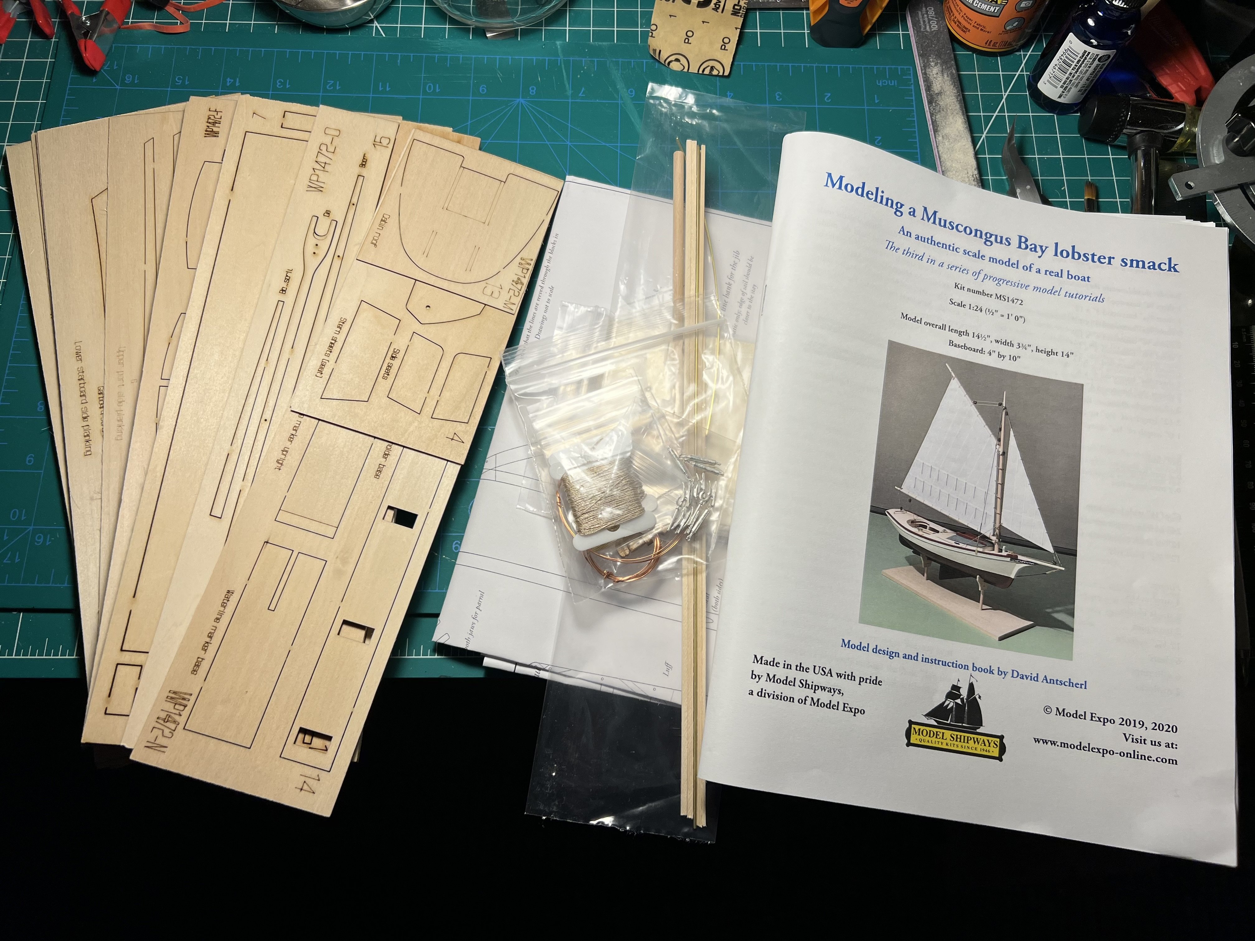
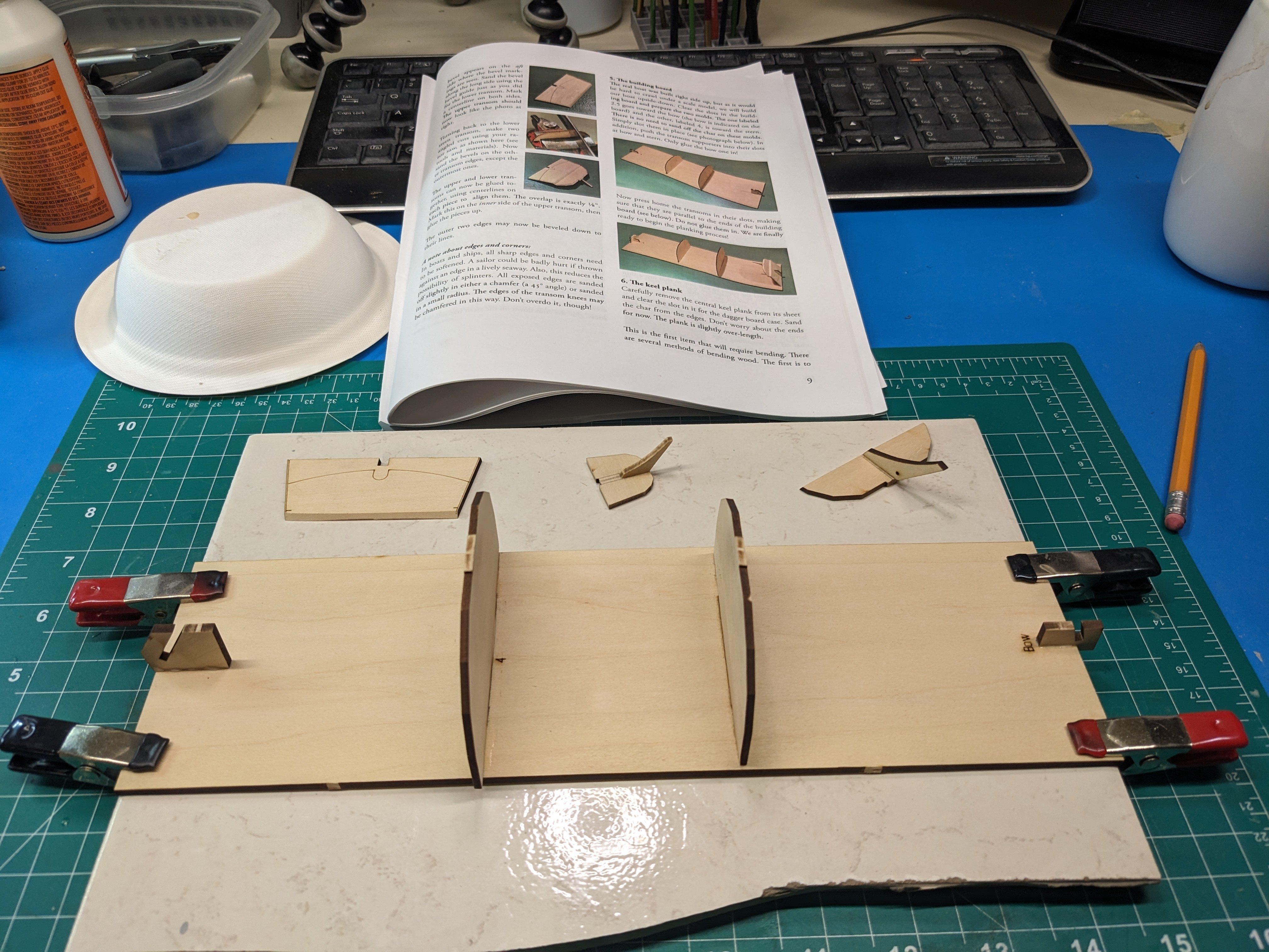
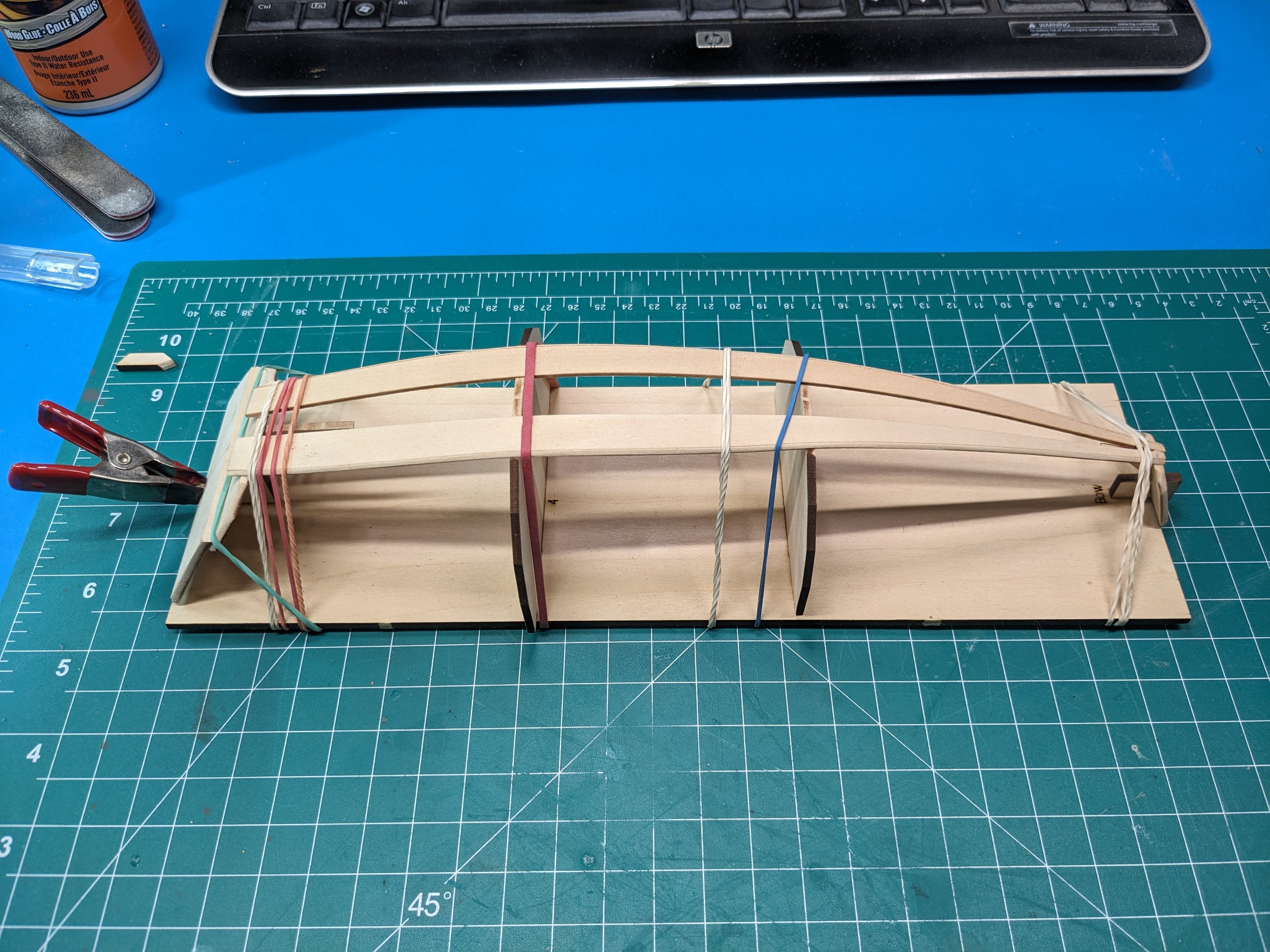
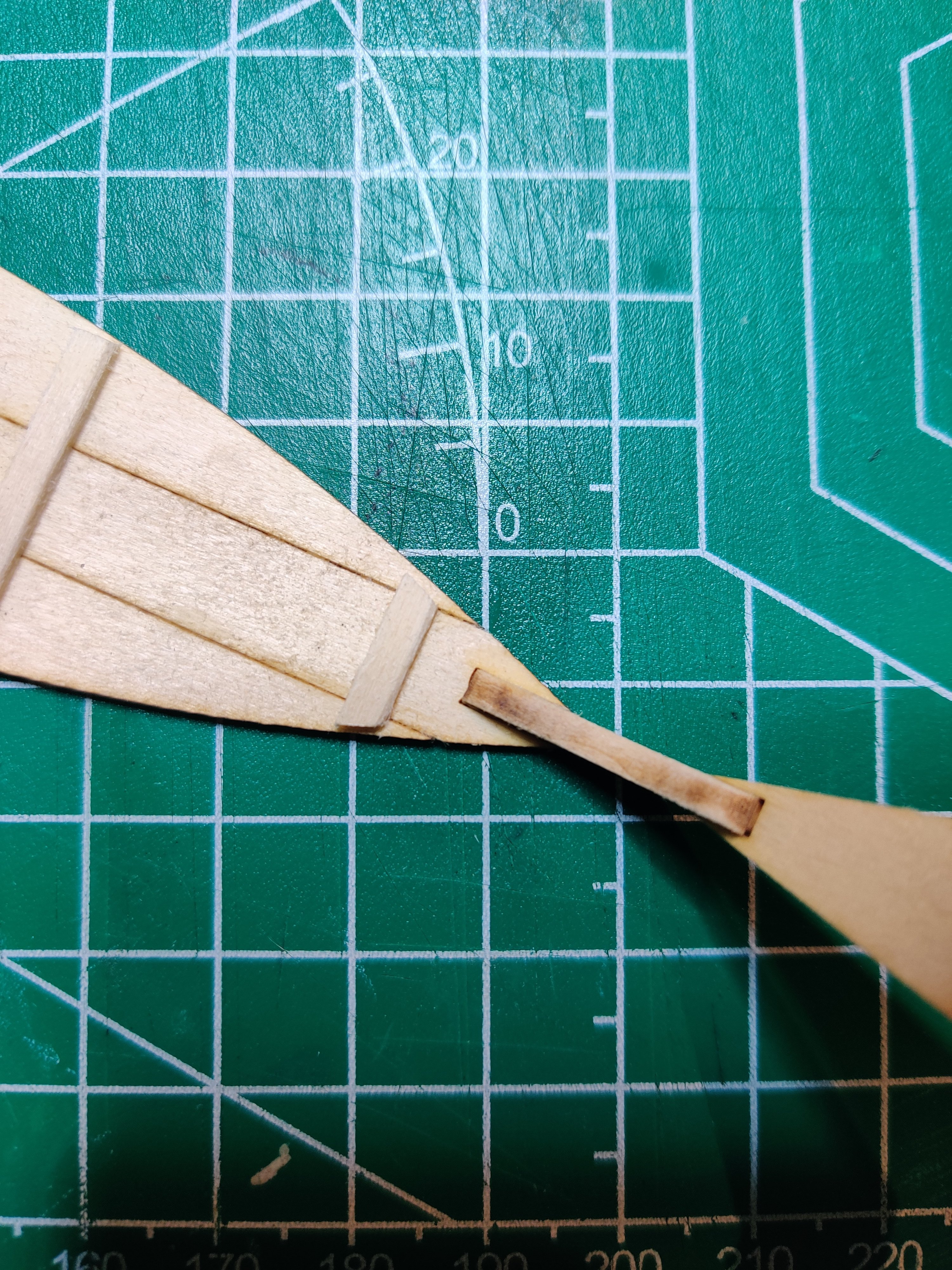
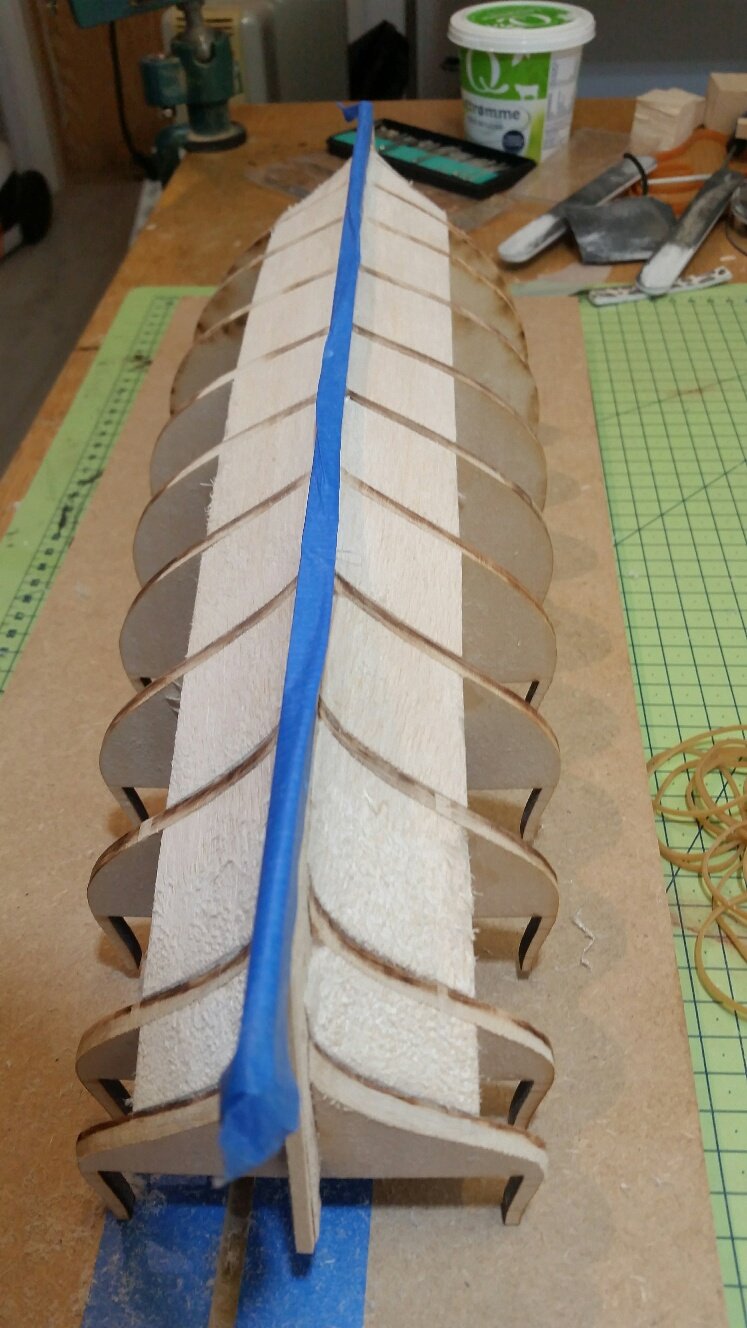
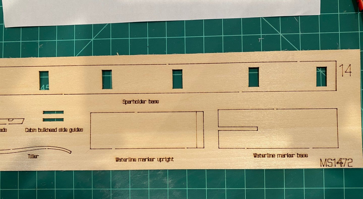
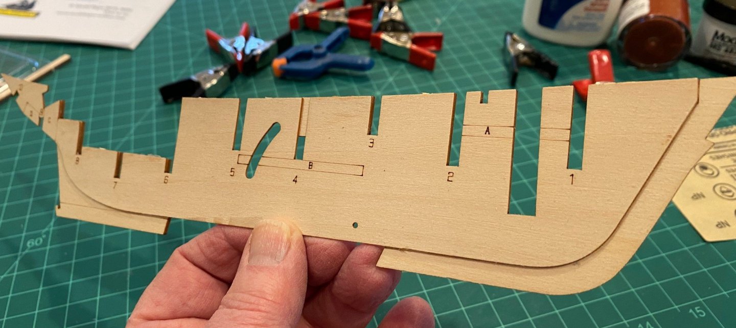
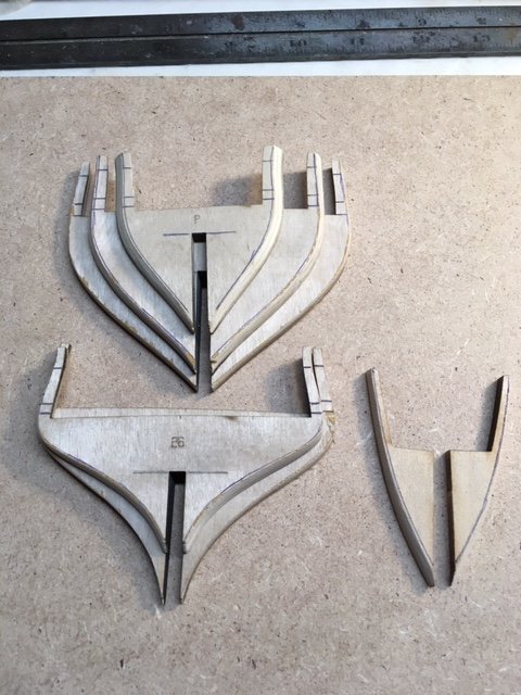
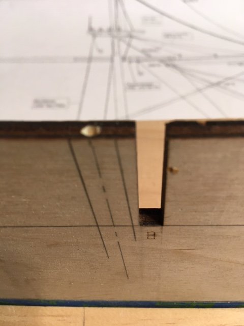
 As I was finishing up the MS 18th Century Longboat, I noticed that the “third in a series of progressive model tutorials” by David Antscherl became available. My first build was the MS ‘Lowell Grand Banks Dory’ and it was a great learning experience. Then I built the MS ‘Norwegian Sailing Pram’ which was the second model in the series, it to was a great learning tool. So now I’m going to try the Muscongus Bay Lobster Smack based on a positive experience with the first two of the tutorial series. I inventoried the contents of the box and all of the parts appear to be there, except that the two ‘Cabin Bulkhead side guides’ were missing from the sheet. It looks like they might have fell during processing the kit and bagging the laser cut sheets. I think I will be able to make the parts from the left over stock since they are simple. Also, sheet 8 was labeled sheet 7. Spine & Centerboard Instructions Step 1 says to start with the Starboard Spine piece and the three center spine pieces. It calls out sheet 1, 2, 3 but sheet 2 has the Port Spine piece which confused me for a few minutes since I wasn’t sure if I should use the Port or Starboard spine piece. Looking at both the Port and Starboard (sheet 5 not 2) spine pieces and the picture on page 4, I confirmed that I should use the Starboard spine piece on sheet 5, this way the laser markings for the future bulkhead pieces was on the outside of the spine. The red sheet call out for Step 1 of the instructions should reference Sheets 1, 3, 5. The starboard spine and center spine pieces glued up nicely, I did use clamps to hold them together while the glue set instead of a weight as the instructions suggests.

- 61 replies
-
- 6
-

-
- muscongus bay lobster smack
- Finished
- (and 1 more)
-
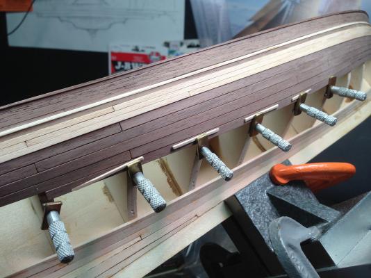
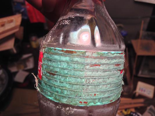
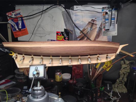
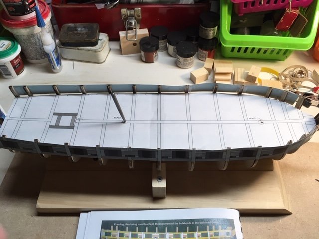
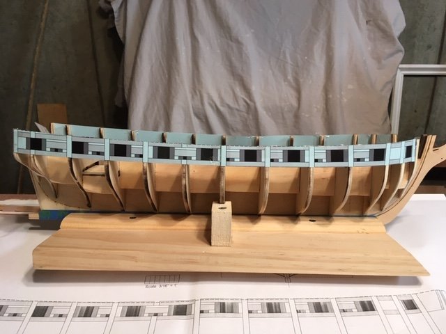
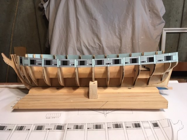
 I’ve decided to start this build log even though it might take me a long long time to complete. This is the Pride of Baltimore from MS, but I am substituting some fine woods I’ve gotten from Hobby Mill and will be adding more guns to the deck. I’d like to make a ship that could have been an 1812 privateer. As this ship is just so beautiful under sail – I intend to make sails and also experiment with coppering the hull with a green patina. I discovered early on that I made a big mistake with the hull. A few of the bulkheads were not symmetrical and I didn’t catch it until I started to plank. I almost ditched the project- anyone who knows ships or modeling would catch it, but I figured that most people wouldn’t so I’m continuing. I missed figuring out how to plank the counter properly also, but will keep it going. This is such an addictive hobby and it is so much fun to be a part of MSW. I have so much to learn from you all!


-
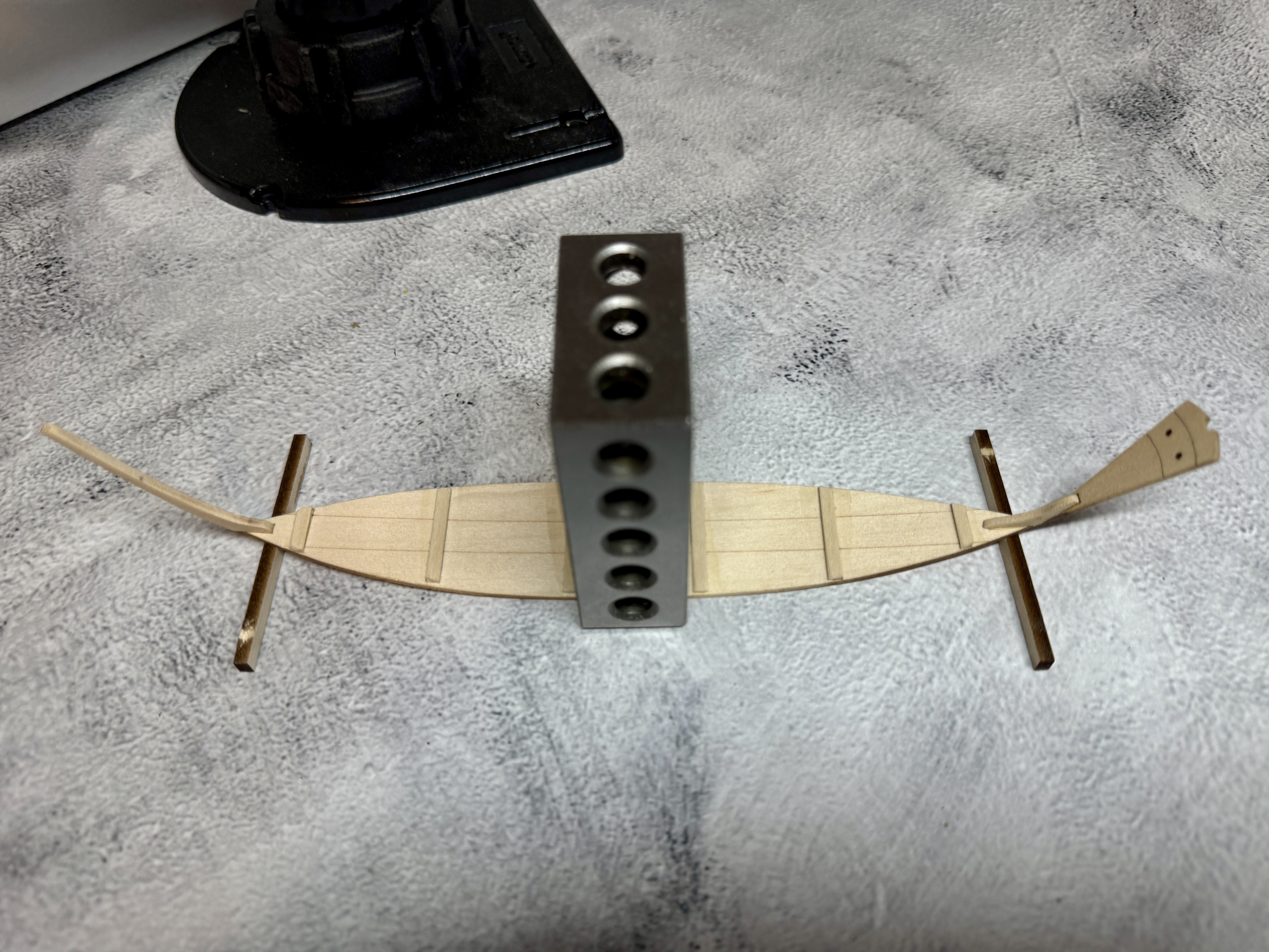
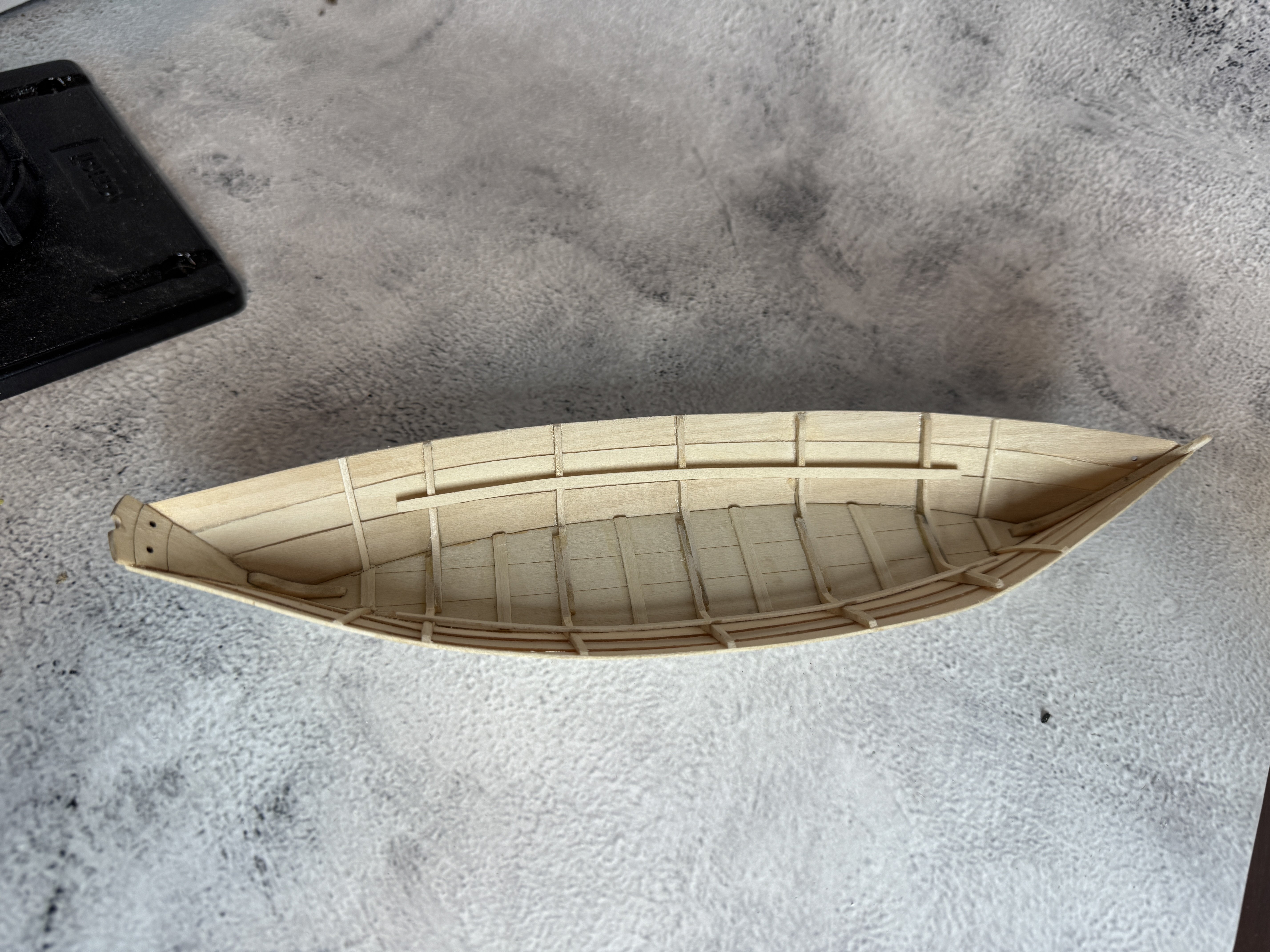
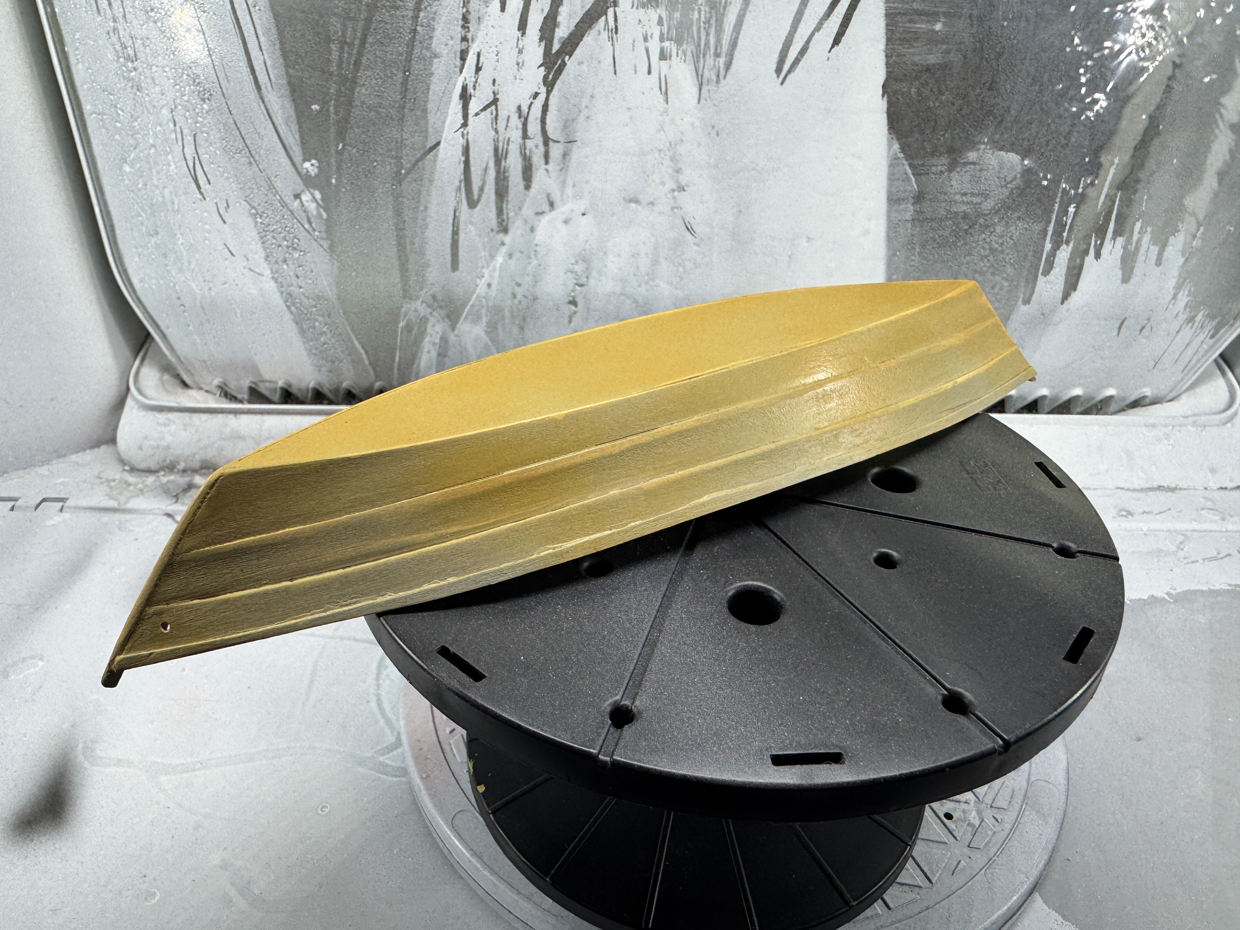
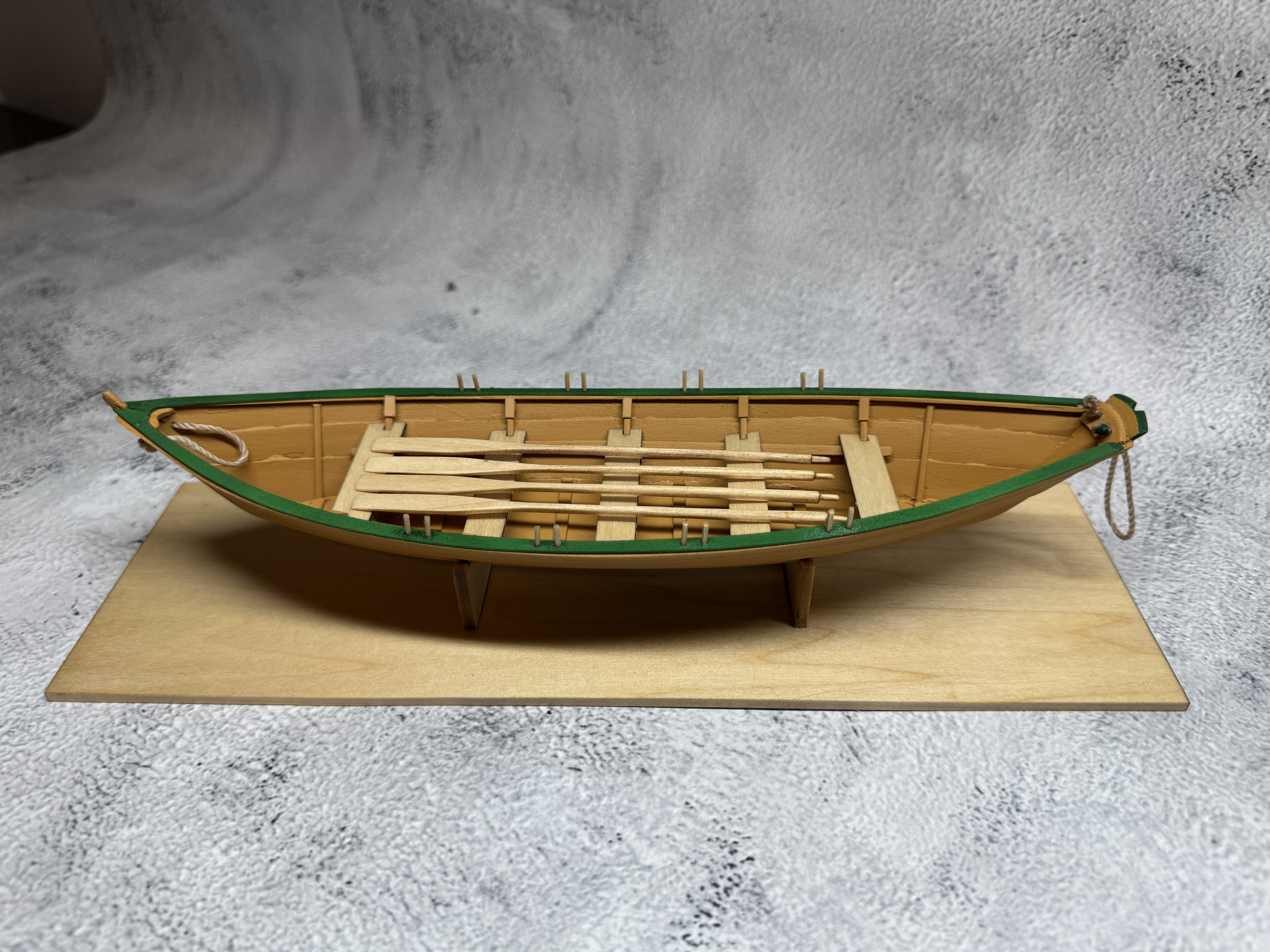
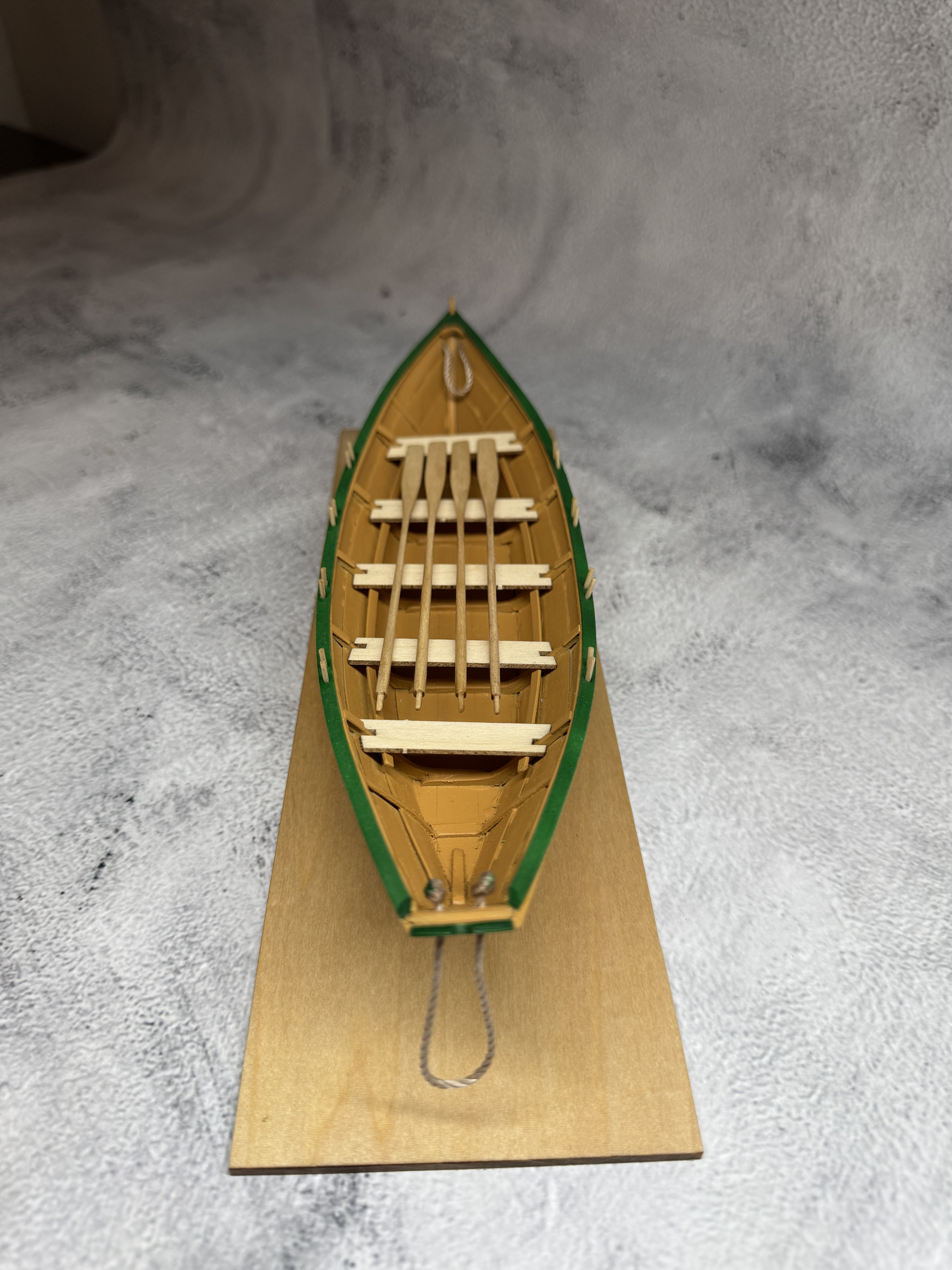
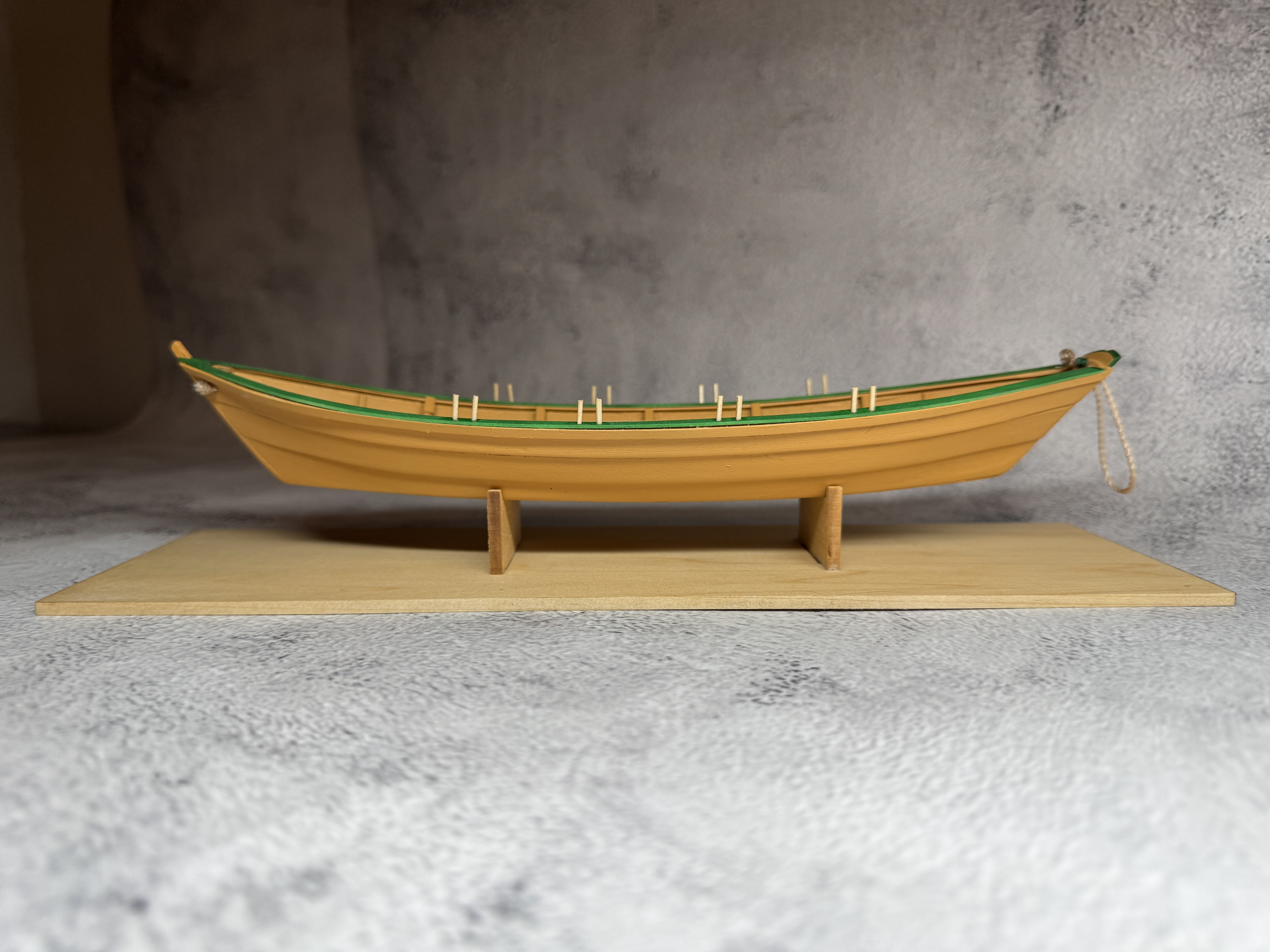
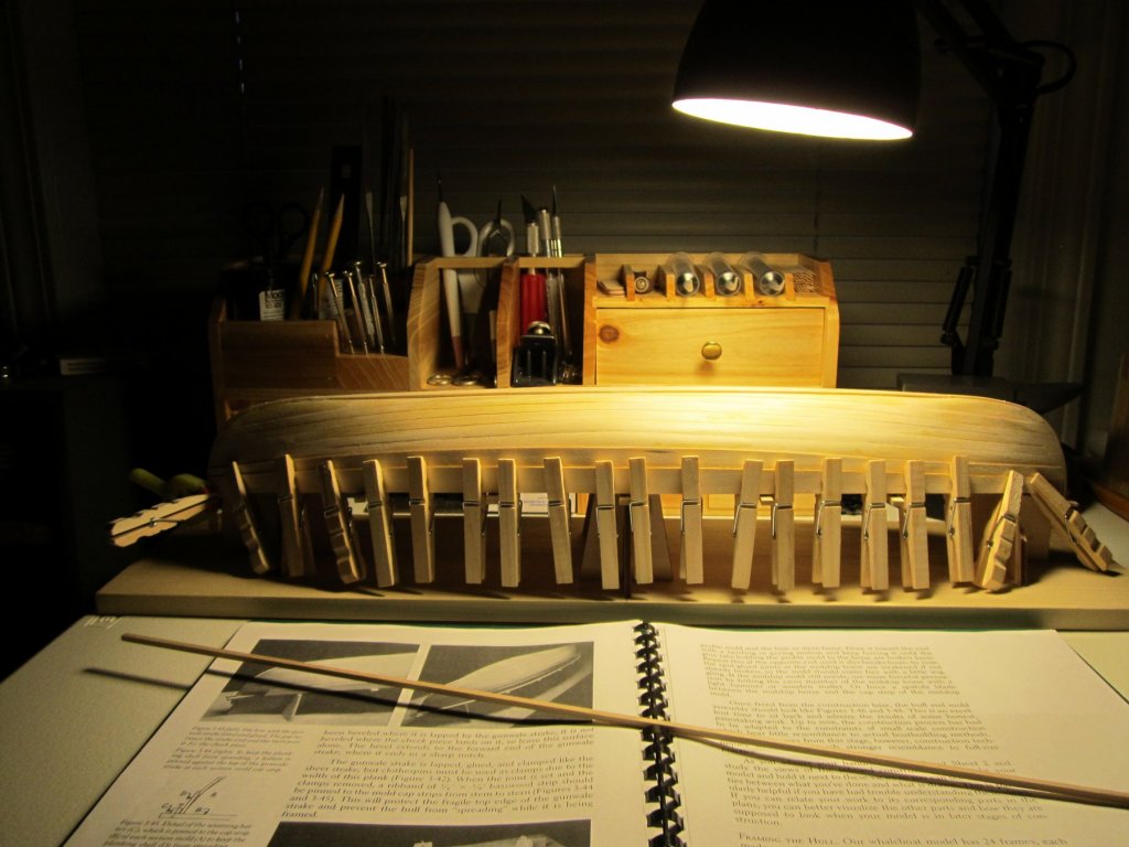
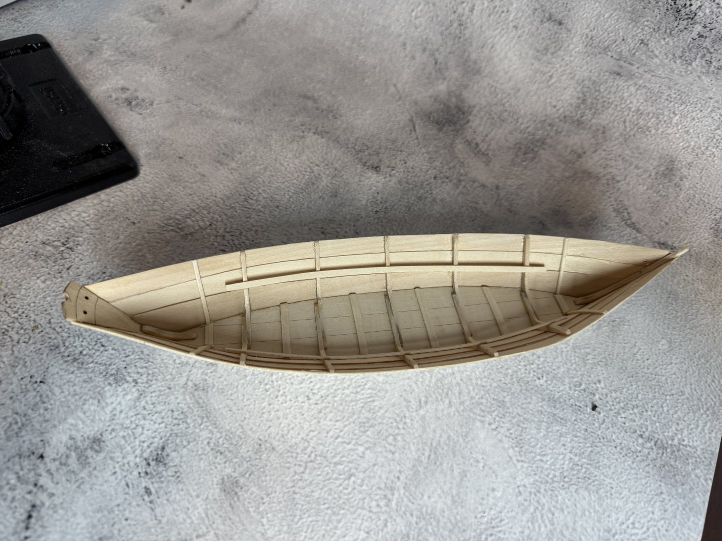
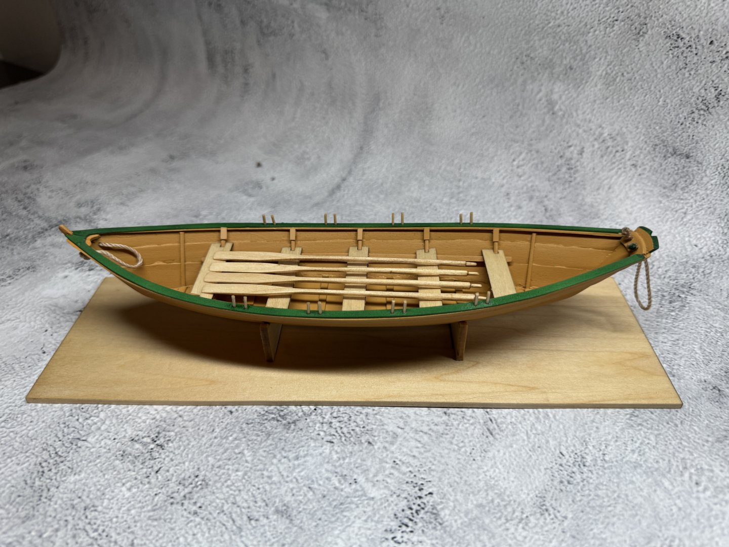
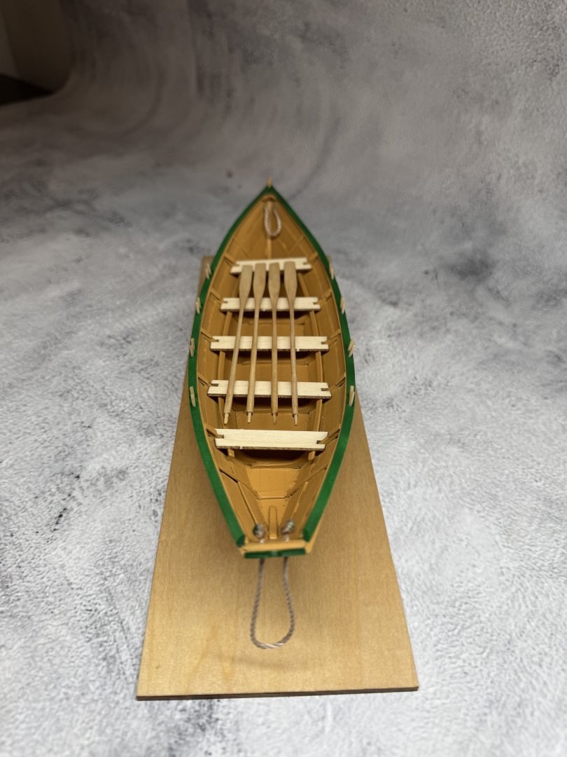
 Back on February 1st of this year, I purchased the Model Shipways New Bedford Whaleboat kit from Model Expo. I have been a modeler on and off through out my life in plastic and card stock models, and now that I am retired I wanted to give a wooden model a try. I have been working a little each day on the whaleboat and I believe I have made good progress. I am at the stage now where the basic whaleboat is together and do have a few question, so I will start posting some of my build photos and hope you all enjoy my beginners efforts!
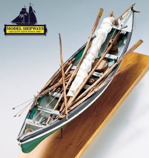
.thumb.JPG.825511f08da7b67cdaf1717be5e41268.JPG)
- 45 replies
-
- 3
-
-
- new bedford whaleboat
- model shipways
- (and 1 more)
-
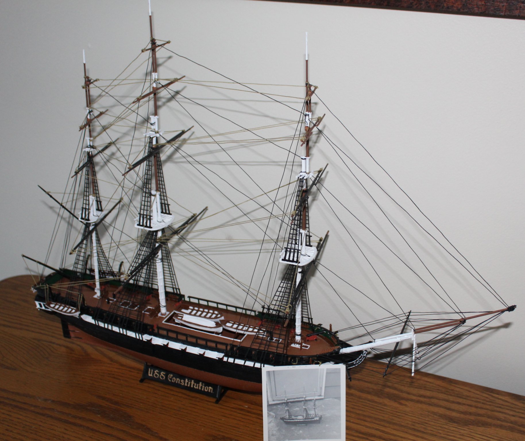
 Motivation - My interest in Constitution goes back to when I was 10 years old. My uncle bought me a 22” Revell model of Constitution – it had a record in the box that that described the highlights of Constitution’s history which I nearly wore out while my dad built the ship for me. I don’t know what ever happened to the model, but I have a photo of it completed (see below). Seeing that photo inspired me in 2020 to purchase the kit off of **bay**, and upon finishing it (see below), I began thinking in larger terms – what about a wood ship model? So here I am, 18 months later, having obtained a Model Shipways kit of Constitution, and having taken some time with the Lowell Grand Banks Dory, Norwegian Sailing Pram, and 18th Century Longboat kits to get some basic experience in wood ship modeling under my belt. I have no illusions of matching the outcomes of the model masters I’ve seen on this site, but I won’t hurry the build along. As I turn 60 next month, my thoughts turn to finishing Constitution before I’m done with this world, and who will get it after I’m gone (I love the picture of xken’s son’s family with his – I hope for similar interest from one of my sons…). Details Modeling Constitution from 1812 prior to Guerriere Battle, possibly before “The Great Chase”. - Stern fashioned after Hull, Revell, and Bluejacket models - Billet Head & Trailboards fashioned after Hull, Revell, and Bluejacket models - 30-Gun gun deck – no bow chase/bridle ports - 24-Carronade spar deck + 1 bow chaser - Ships Boats – Captain’s gig & cutters in the davits, undecided about the hatch for now. Model Examples I will follow - Isaac Hull Model (Peabody Essex Museum) - Revell 1:96 Model - Bluejacket Model - Others as depicted on Model Ship World Modeling Resources - Model Ship World builds – many - Model Ship World model techniques - various Books & Papers Resources – this list will grow as the need arises - A Most Fortunate Ship – Martin - All Sails Up and Flying – Eriksen - Anatomy of the Ship – Marquardt - Constitution Close Up – Martin - Constitution Practicum – Hunt - Rigging Period Ship Models – Petersson Plans and Misc Resources - USS Constitution Museum – Modelers Resources - US Navy - Bluejacket Models (undecided) - Historical Paintings – difficult to sort out for accuracy Photographs - A “bazillion” online images and videos One thing that is somewhat discouraging is the number of attempts at this model that have apparently been abandoned. I have no doubt that every one of you who set it aside in the end started out with much enthusiasm as I carry today. Only time will tell. I do have a life beyond modeling - wife, children, and grandchildren. Oh, and work. Therefore you won't see progress moving along at a quick pace. However, if you stick with it, so will I. Looking forward to the ride... Midshipman 3/c (Ret) Bob
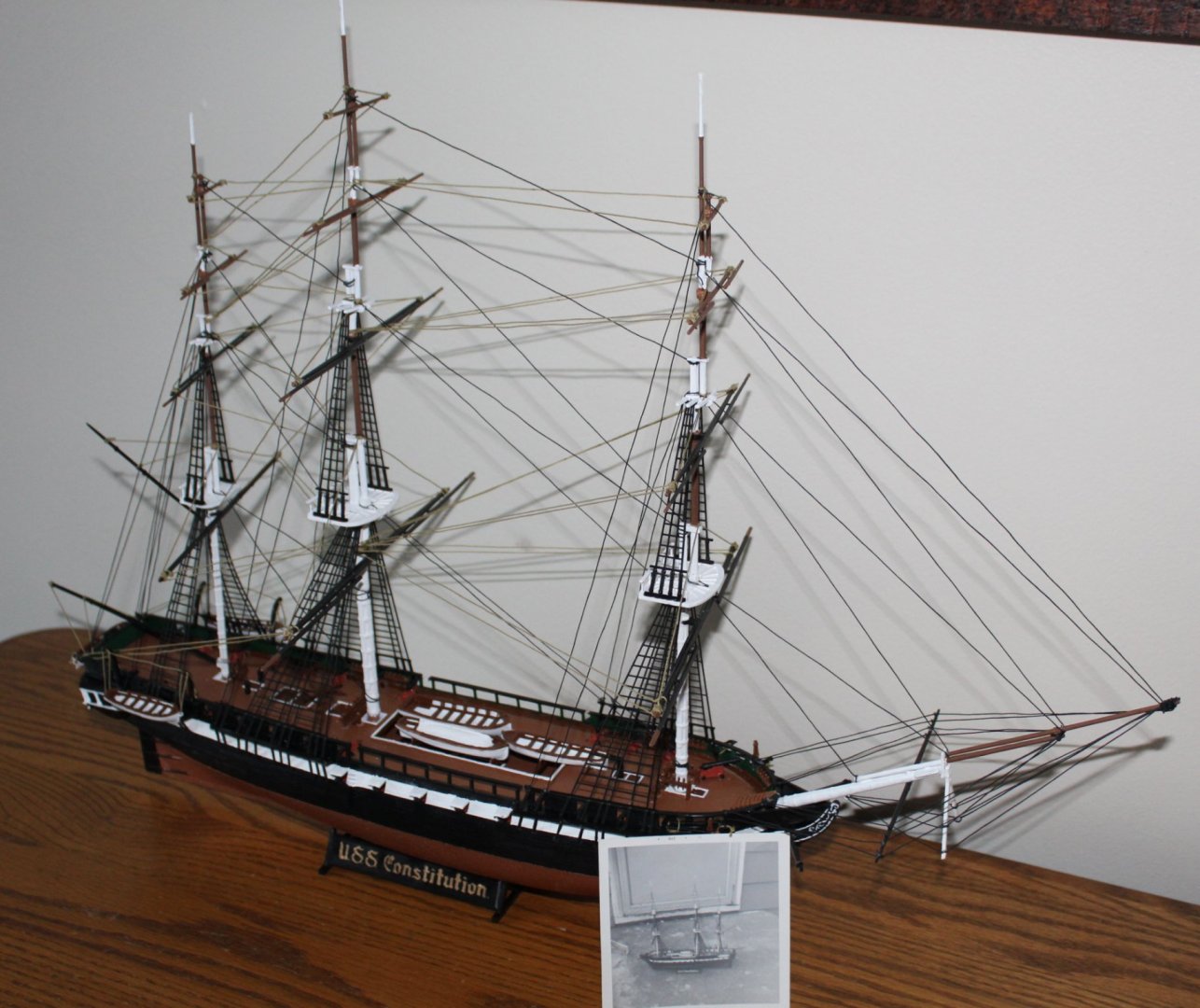
-
 Good Evening Everyone, I know most of you and hope you will continue with me on my building journey, this time, the Rattlesnake…American Privateer. After getting my feet wet with the Lady Nelson, I do plan to slow down on this one and really try to do it as perfect as my skills will allow and be as accurate as I can at the same time. I suspect this build will also fall into the “kit bash” category because there are just to many components that I am disappointed to find in the box (for instance, all the blocks are from Amati). I am in good company on this build with javajohn and OldSalt1950 building the same kit and Gregory building the kit in 1:48. The journey begins with an inventory and a wish list for replacement parts and components.
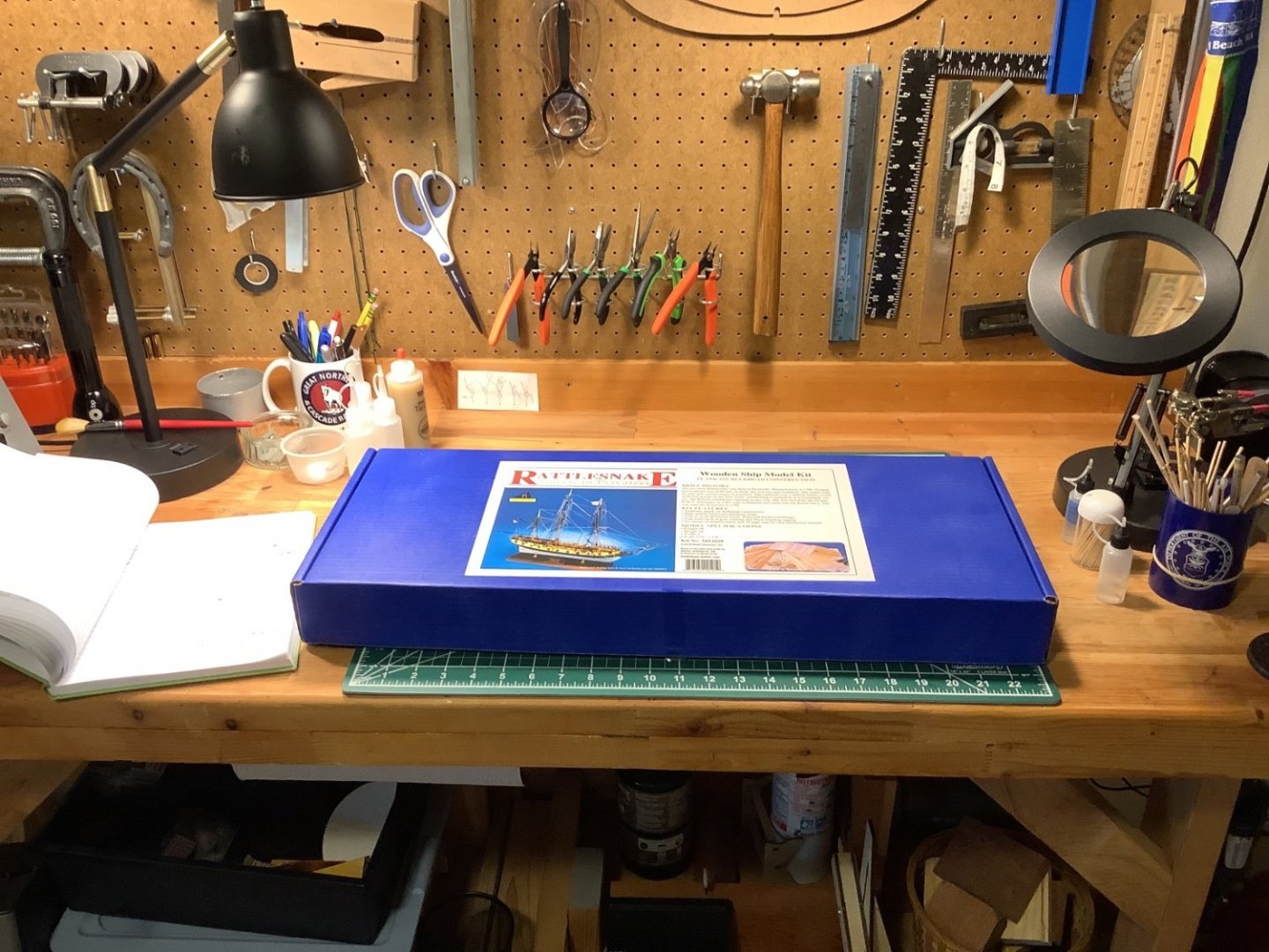
-
 I am one of the many working my way through the Model Shipways beginner's series. There were already many and excellent build logs for the banks dory and I had nothing to add to those, until it came to scratch-building the fishing gear. I doubt that anyone will want to follow me down that path, so I did not prepare a log for that build. Now it's time for the pram and I think that, this time, I will have something to contribute. If nothing else, I can offer a sailor's perspective. I'm not the only one here who can do that, but I see that some people come to the kit without experience of small, traditionally rigged boats. That can be limiting, considering the abbreviated (not too say "deficient") instructions. It will be a little while, maybe as much as a couple of weeks, before I put craft knife to basswood. However, I have started preparations, so this is probably the right time to start a log. First, I figure that it's a good idea to have a vision of where you want to end up before starting out. I may be unique but the dory meant something to me, emotionally, and was always more than a learning and building exercise -- though it was that too. In contrast, I can't feel much affection for the pram. I can and do love small, traditional boats but I love them in full-scale, for sailing. I just don't feel much interest in them as subjects for modelling. Maybe I will one day scratch-build a miniature of my own pride-and-joy (a Drascombe Longboat, if anyone cares) but I just can't get excited about recreating another man's recreational toy. So the pram kit will be learning exercise only, for me. I'm not aiming for any embellishments, just a stand-alone display model. That's a shame in a way as 1:12 is a common dollhouse scale, and those so inclined could dress up a finished pram with any number of accessories (wine bottles keeping cool under the sternsheets, perhaps?), as well as figurines of humans and their pets. That's not for me, though. Still, there's no denying that the prototype is a pretty little thing -- much prettier than the plywood pram that was my first boat, a lifetime ago. So I aim to emphasize her prettiness in a finished model. To meet its objectives, my dory needed a good thick coat in a shade still known in this part of the world as "dory buff", but it hurt to hide all the woodwork that I had sweated over under that first coat of primer! So I aim to give the pram a clear finish, which means that she has to be built without glue stains or filler (save for a little white glue and sawdust mix, if necessary). That will add to the challenge and hence to the learning experience. Or I hope so. Enough preliminaries. Next: Preparatory steps. Trevor
 -
 Well then... haven't been on in a couple of months and have found that, well, everything is toast. Sad. But not to beat the already dead horse i'm going to ask you all before reuploading pictures. Should I go back and repost what I have done, or just pick up where i left off? My gut is telling me everything up till now, as to restore some posterity. it's just a coupl of years worth of stuff, and I hope I remeber it all enough to do it justice. With that said, welcome back everybody!
- 61 replies
-
- 1
-
-
- prince de neufchatel
- model shipways
- (and 1 more)
-
 I only have photos of this build as it was completed rather quickly.


- 16 replies
-
- 12
-
-
- dory
- Model Shipways
- (and 2 more)
-
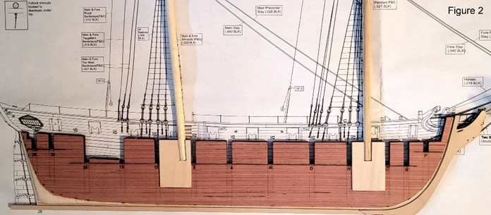
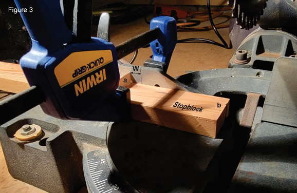
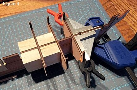
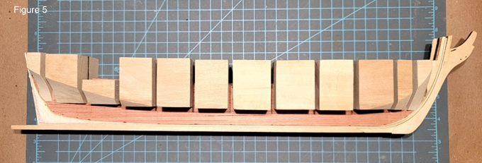
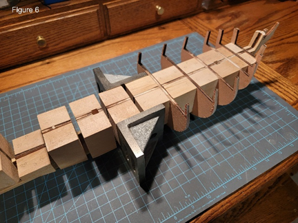
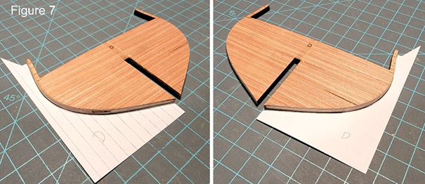
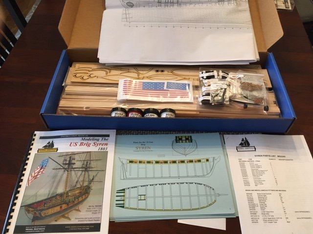
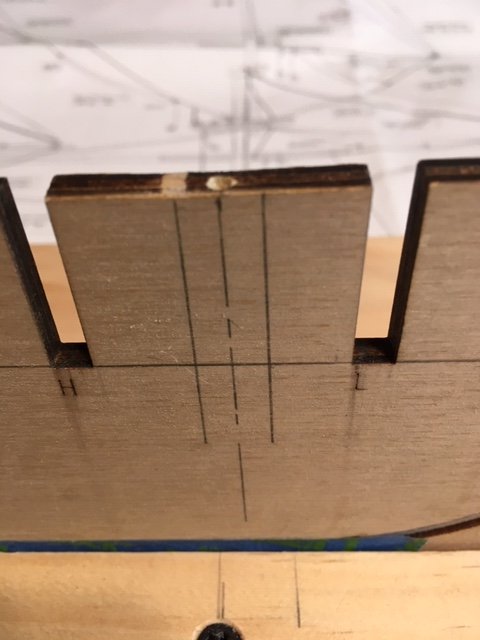
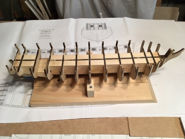
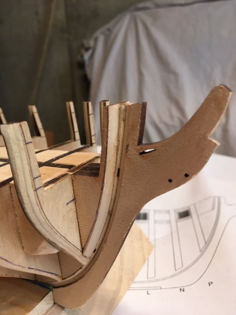
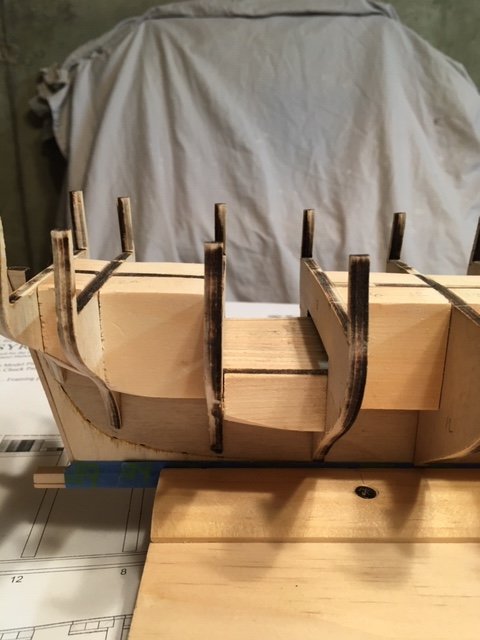
 A few years ago, I purchased four Model Shipways kits plus boxes of spare parts. Why I purchased these, I don’t know. Maybe, it was related to the “Pirate ship” I saw at a friend’s house when I was eight. It was the most fantastic ship I had ever seen. The detail was incredible. My friend said that his dad had built it. That experience started my model building era. My first attempts were simple wood boat and plane kits. This led to rubber band powered airplanes, then as I got older, gas-powered control line airplanes. Since I could not control them, it tried gliders. These were great except they seem to continue to glide out of sight. Finally, I tried radio-controlled boats (I skipped radio-controlled airplanes because they crash). The last models I built were Sterling models of the USS Missouri and the Chris Craft Corvette. That was 60 years ago. Brushing the dust off the various boxes, I decided to build the US Brig Syren (Model Shipways Syren kit MS2260). Mainly because it had the most readable/detailed instructions. Reviewing the manual, it became clear that this was not a model for a beginner. After some research, I decide to buy the Model Shipways Wooden Boat 3-Kit Kombo to see if I still had the skills to tackle building the Syren. In October (2022) I completed the last of the three kits. They looked OK to me; therefore, I decided to give it a go. During my research phase, I ran across this website, and decided to join. Reviewing the build logs, I found over 50 that had, or were, building the Syren model. Skimming through these logs I became aware of many issues associated with building this model and a significant amount of knowledge available on the site to deal with these issues. The question I had was whether to start my own build log, or just read those that were already posted. Without answering this question, I started building the Syren in November (2022). I kept waffling on the question until recently when I saw three new Syren Build Logs posted. Why not a fourth? So, here I am. Started the build on November 19, 2022 by reviewing the contents and verifying that the kit was complete, and that all parts were in good usable condition. I plan to follow the instruction manual included in the kit (Modeling the US Brig Syren 1803 prepared by Chuck Passaro); plus, comments from the Build Logs on the Model Ship World web site. Completed steps to date: 1. The bulkhead former was lightly sanded using 150 grit sandpaper. Only the loose laser char was removed. I read that removing the char does not necessarily improve the glue bond. This was tested by gluing two scrap charred edges together using Elmer’s Carpenter Glue. After the glue had set over 24 hours, I separated the two pieces. The fracture surfaces were nonhomogeneous, meaning parts of one piece were still attached to the second piece, which indicates a strong bond. 2. Contoured the 3/32” x 1/16” basswood strip to the bulkhead former and glued in place using Elmer’s Carpenter Glue. Also, glued the stern 3/32” x 1/16” basswood strip and the 3/16” x 3/16” basswood strip keel. 3. Used French Curves to draw the beard line on the port side using the burn through marks for alignment. Carved the rabbet from the port and starboard bearding lines as described in the manual. Sanded as best as I could. 4. Before starting on the bulkheads, the bulkhead frame was modified by adding slots for the masts. Several build logs described doing this by transferring the orientation of the masts to the bulkhead former using the provide plans. An analysis of seven builds that predrilled mast holes found a significant variation in the placement of the mast slots in the bulkhead former. The distance of the center of the mast from the bottom stern edge of the #8 bulkhead slot ranged from 3/16” to 3/8” with an average of 5/16”. One possible cause for the differences may be that the plans are scaled slightly smaller than the actual model. Because the builds had good results, it seems that any offset between 3/16” to 3/8” of the mast slots should work. Mast angles were determined using Syren Sheet 4 – Inboard plan, Figure 1. Decided to use a distance of 9/32”. As done by others, I used 1/16” basswood to box the slots, Figure 2. 5. Removed all the bulkheads and tested them in their slots. All were relatively loose. Decided to use spacer blocks rather than shims to stabilize the bulkheads and to make sure the bulkheads are aligned at right angle to the bulkhead former. The filler blocks were made from 1” x 2” basswood. Because I wanted to test the symmetry of the bulkheads (suggested by Frank Mastini; Ship Modeling Simplified) after fairing, the bulkheads were not glued in place while making the filler blocks. Prior to cutting the filler blocks, the distances between the different bulkhead slots were measured several times using a caliper. Within 0.01”, several bulkheads were separated by similar distances: L→N, N→P, 24→26: 9/16” (0.55”) D→H, H→L, 4→8, 8→12, 12→16, 16→20, 20→24: 1 5/16” (1.30”) X→D, 4→X: 1 ½” (1.50”) To cut filler blocks of similar widths, a stop block was added to my 10” miter saw (Figure 3). The width of the block (W) was set by measuring from the black vertical line on the miter saw fence to the vertical stop (a) on the stop block. When “a” is aligned with the vertical black line, the edge “e” is at the saw blade. Before cutting any fillers, the horizontal and vertical cuts of the miter saw were verified to be right angles. Filler blocks were cut slightly oversize, then sanded to fit using an inexpensive disc sander (purchased at Menards). For each of the three filler block widths, a first pair of blocks was cut and tested between the two appropriate bulkheads. After the width was verified, the remaining blocks of the same width were cut and sanded to fit. To align the bulkheads, I used a method similar to that shown in a figure in the builder’s log of US Brig Syren by Rafine. I ordered two 3” x 2 ½” x 2” slotted right angle plates from Amazon (cheapest I could find). Starting with bulkheads X and D, one right angle plate per bulkhead was used to align bulkheads X and D to the bulkhead former. The distance between the two bulkheads was measured at the bulkhead former and the port and starboard edges of the bulkheads to insure they were properly aligned. Two filler blocks were cut slightly oversized from the basswood. The cut edges of the blocks were sanded until they fit snuggly between the two bulkheads, then glued in place. For the remaining filler blocks, the appropriate bulkhead was aligned using both of the right-angle plates, Figure 4. In my hurry to finish the filler blocks, I neglected to do preliminary shaping of the filler blocks that extended beyond the bow and stern bulkheads. A Dremel tool with a double cut tungsten carbide burr was used to do the bulk reduction. Final contours were achieved by sanding using sandpaper grids of 60, 100, and 150, Figure 5. 6. The bulkheads were not glued in place; therefore, they could be removed as desired during the fairing. When in place, the bulkheads were very stable and did not move significantly during the fairing. To simplify the process, bulkheads X through P were faired together, Figure 6, followed by 4 through 26, then D through 8. By doing the fairing in sections, it was easy to hold the bulkhead former during the sanding. It also helped avoid breaking the thin extensions. Unless you drop it, which I did, resulting on one broken extension. This was glued back in place, and reenforced with basswood. I also learned not to sand the bulkheads using a bow to stern motion as this removed some of the wood from the bulkhead; especially in the extensions, Figure 6. 7. At the completion of the fairing, the contours of each bulkhead were compared to the contours shown on Syren plans. Templates were made by transferring the contours to 4”x 6” index cards using graphite paper and a metal stylus. A sharp #11 Xacto blade was used to cut the card along the transcribed line. Comparisons to the templated were easy to do because the bulkheads could be removed from the bulkhead former and laid on a flat surface, Figure 7. Where a bulkhead contour differed significantly from the template, filler pieces were added, then faired to shape. This method helped to maintain the symmetry of the fairing. This is where I am today. My next steps will be to glue the bulkheads and test the fairing as described in the manual. I added figures using cut and paste method rather than uploading. When uploading, the size of the images was in the megabytes. I didn't think that kind of resolution was necessary for these image.
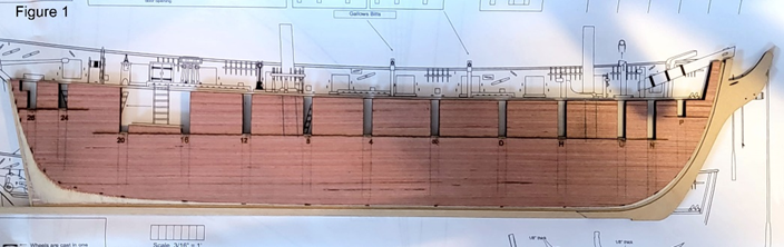
-
Another build where I have enjoyed the building more than the logging.


-
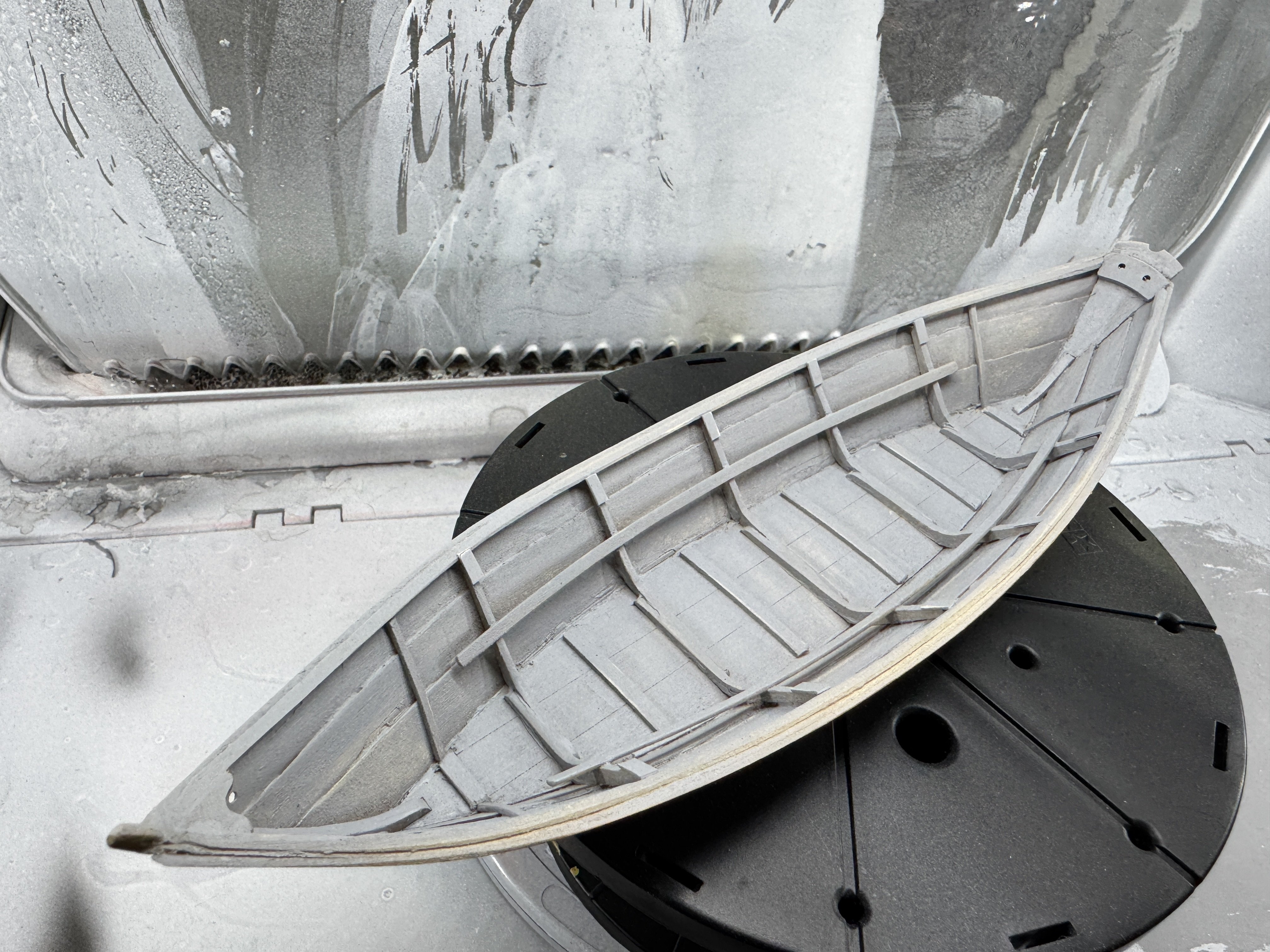
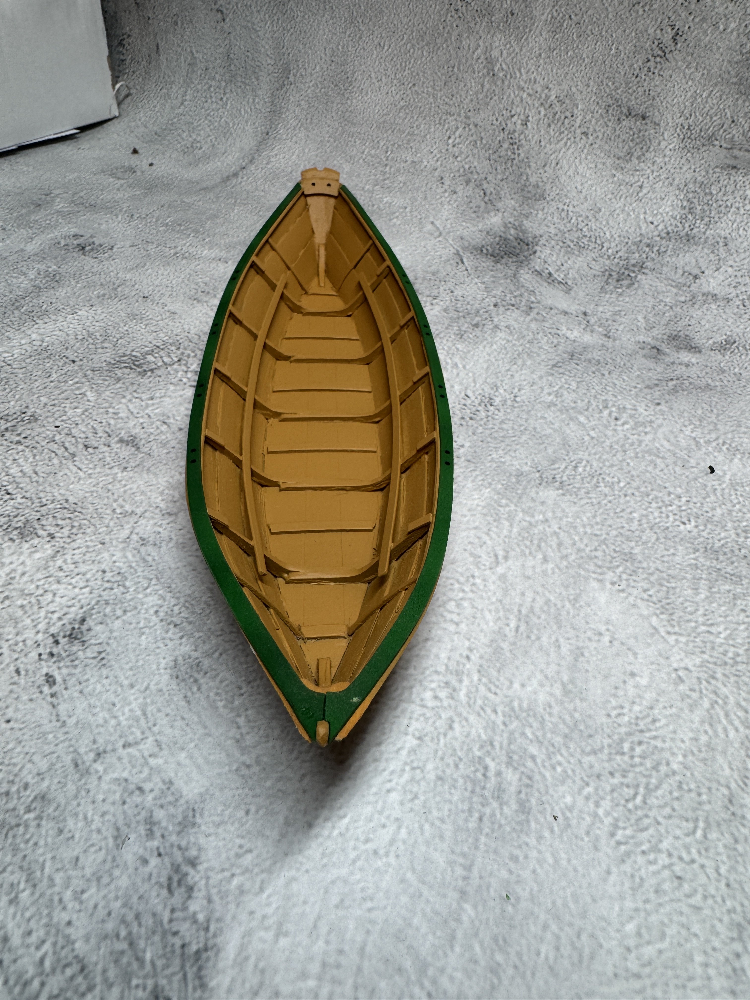
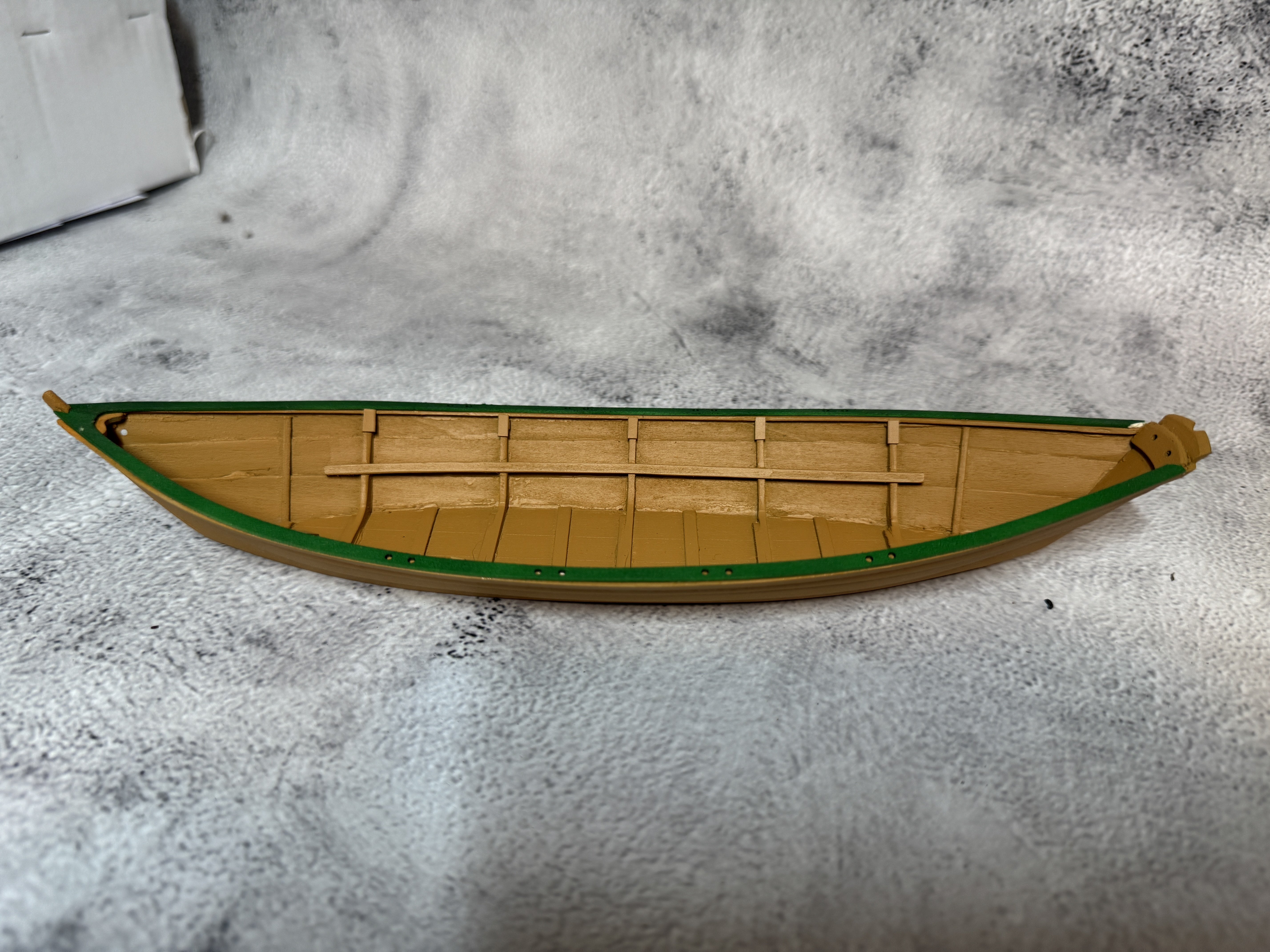
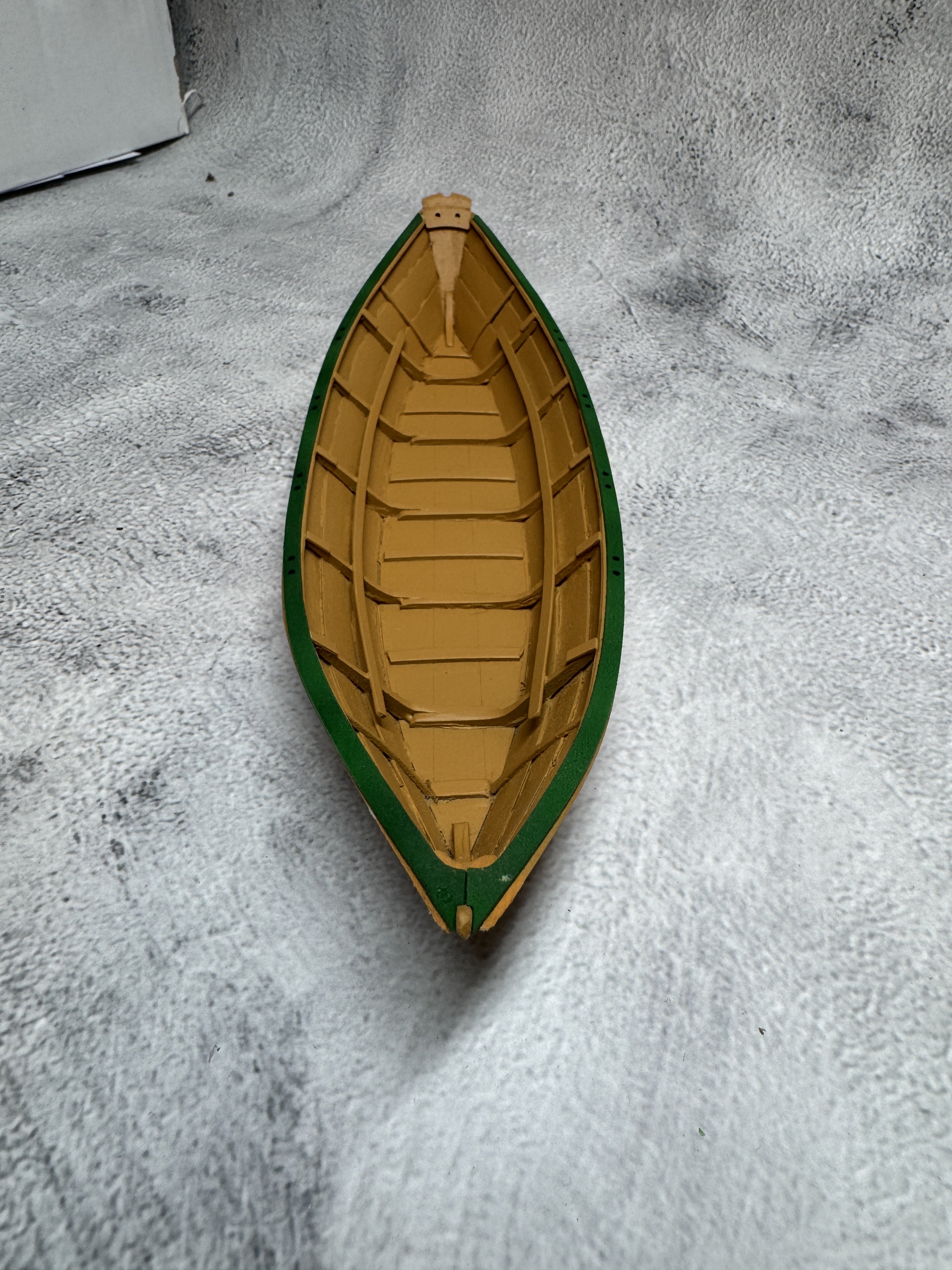
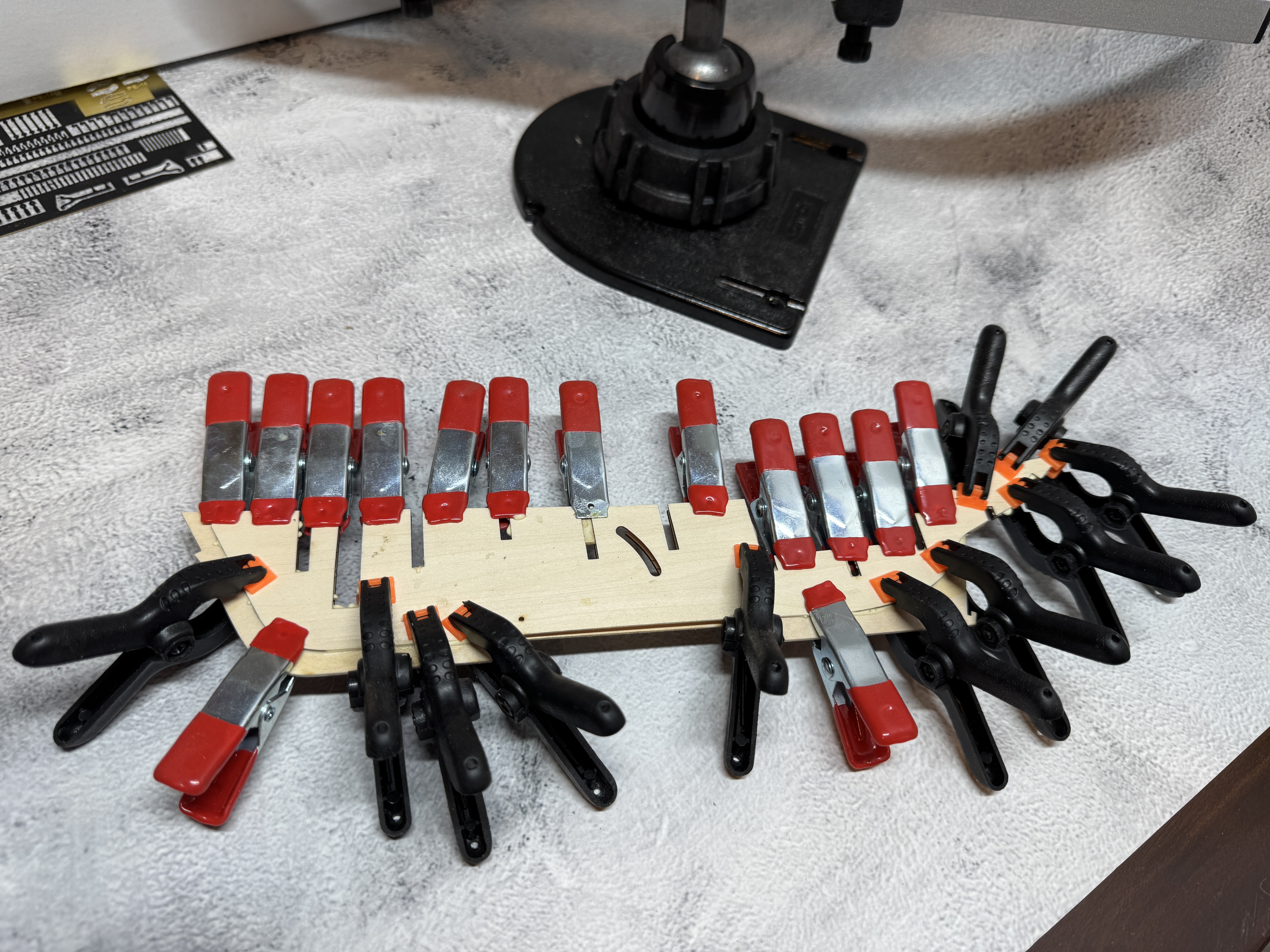
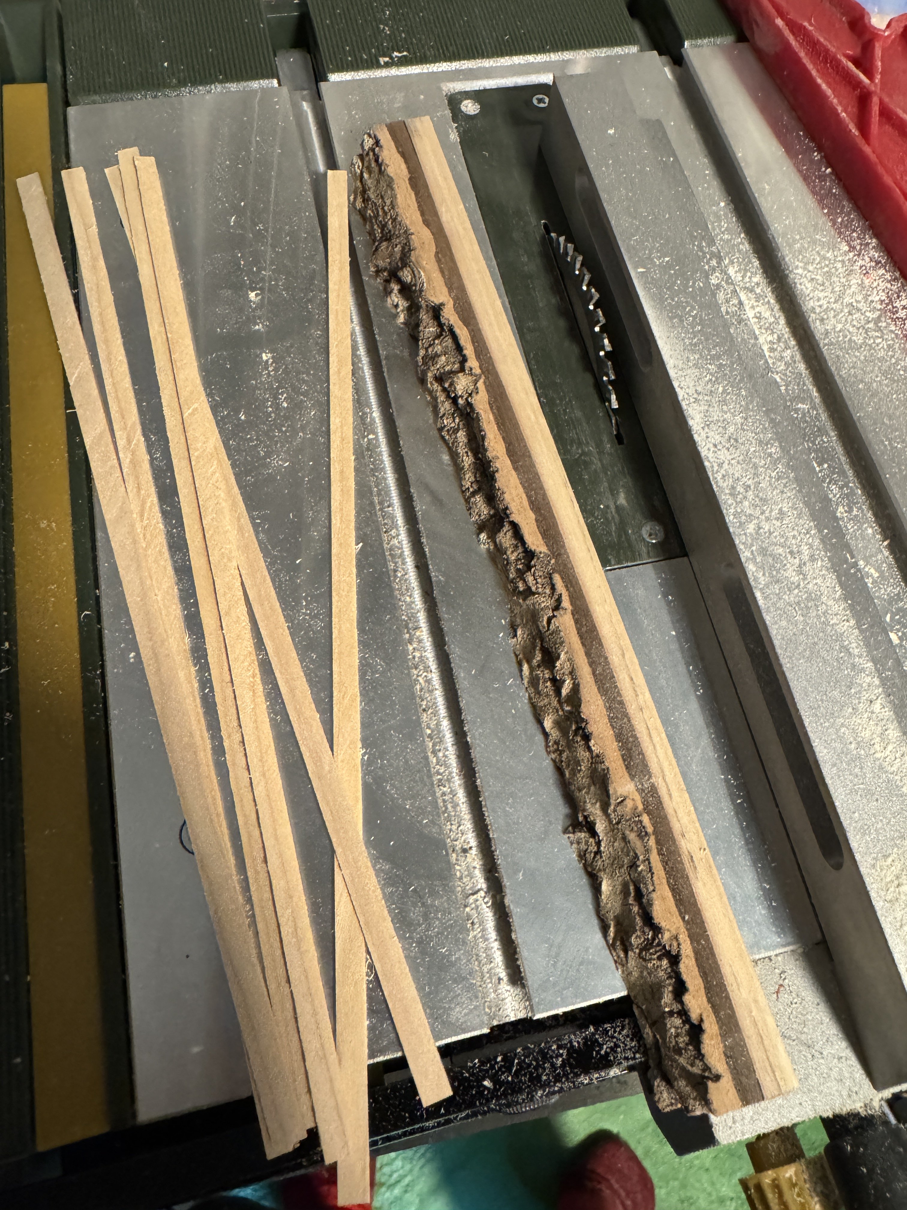
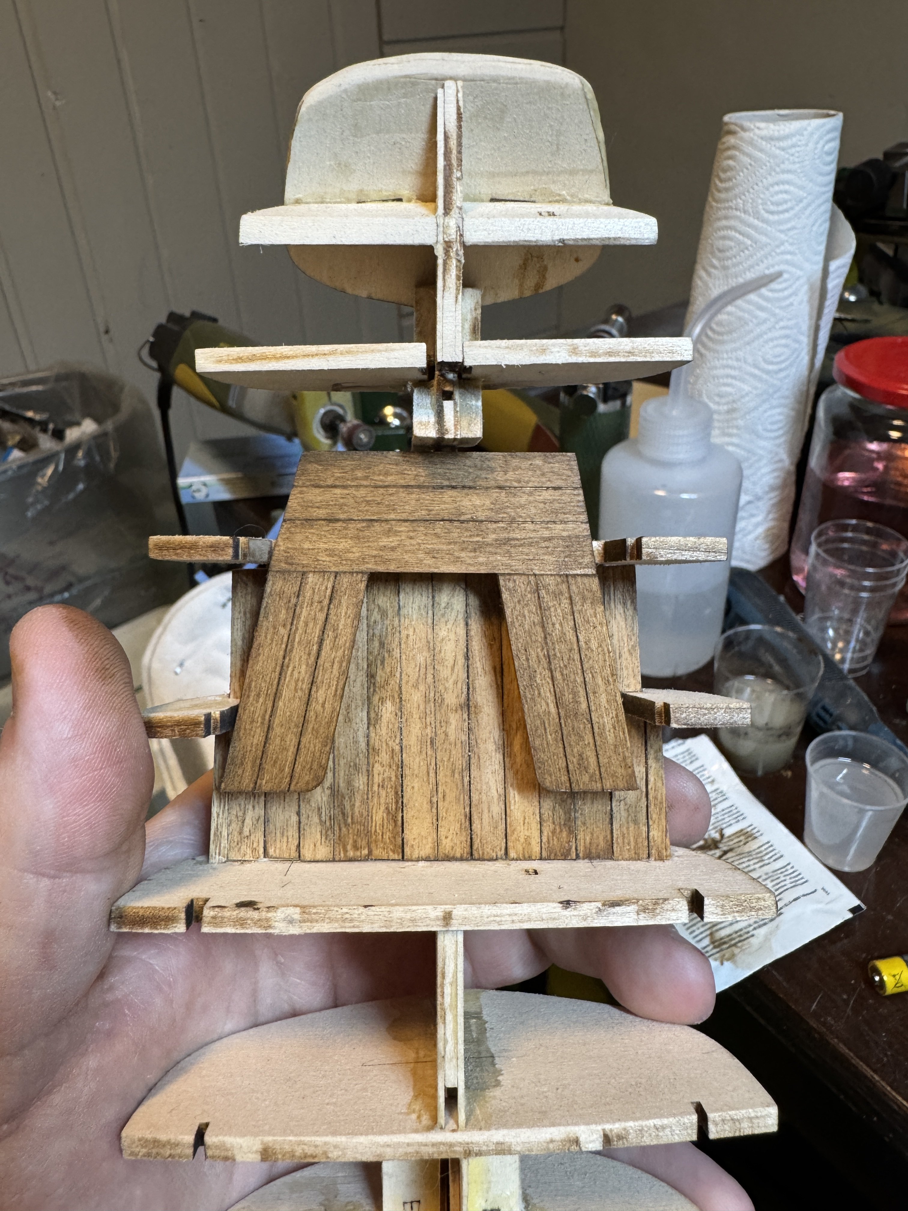
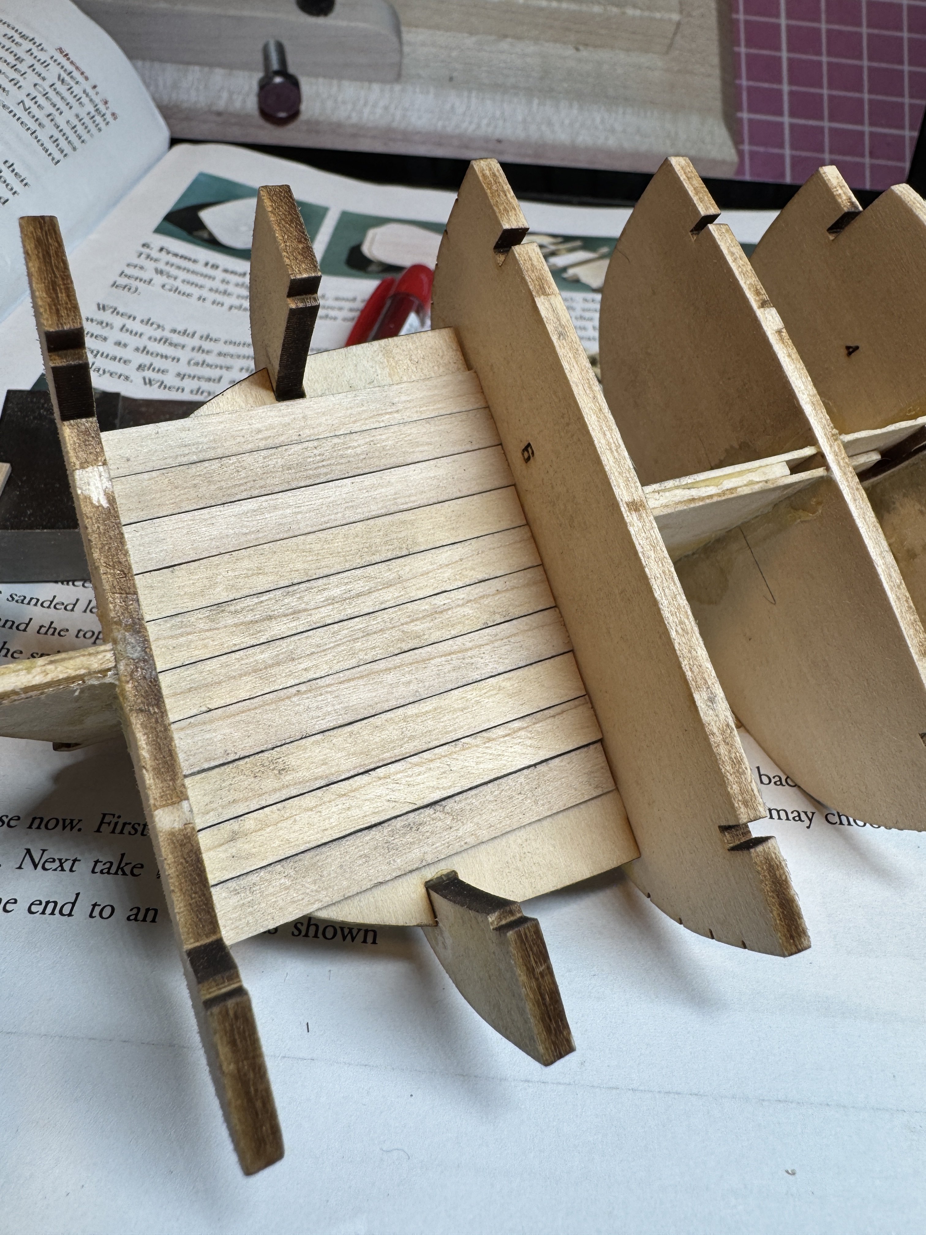
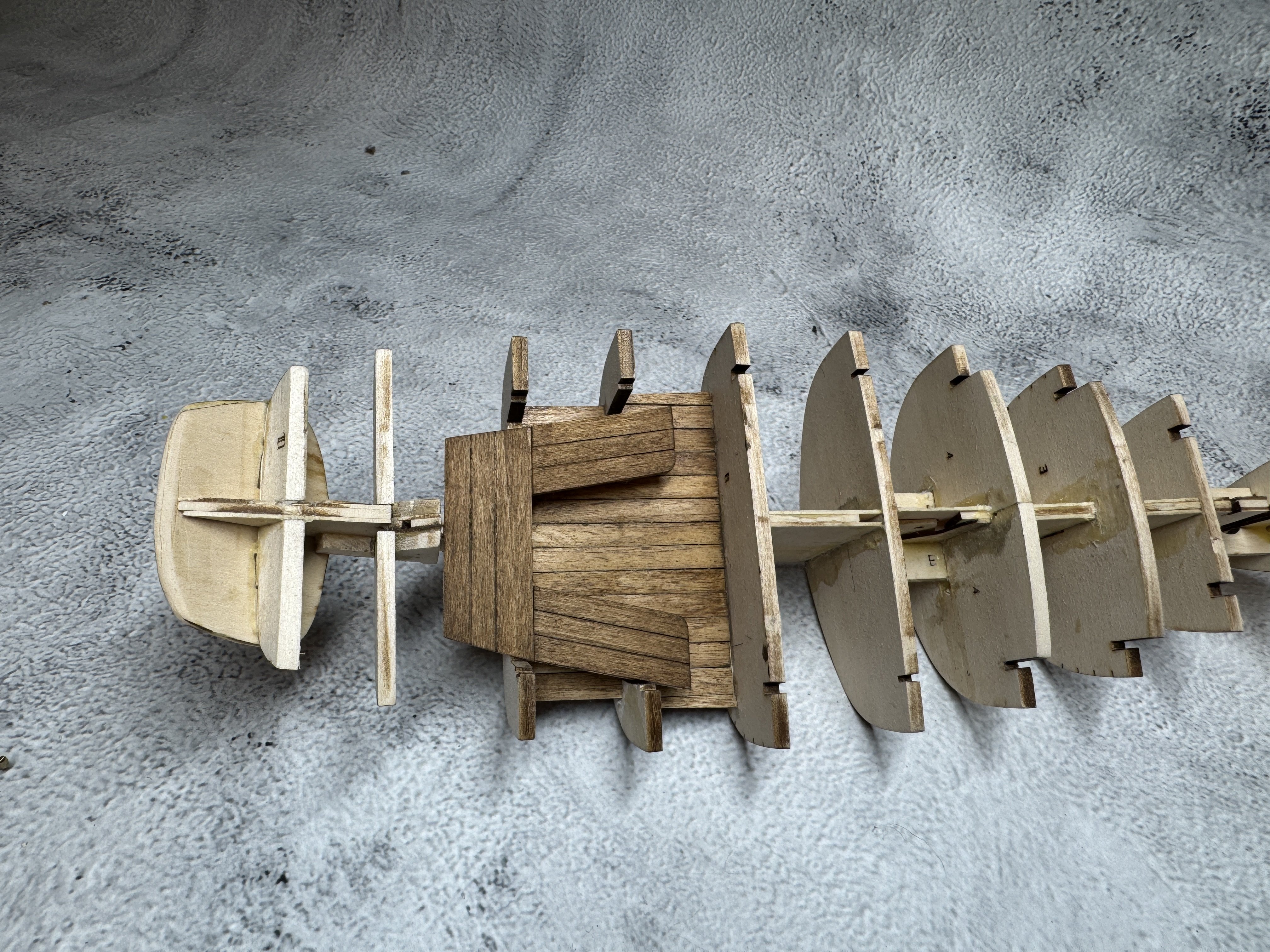
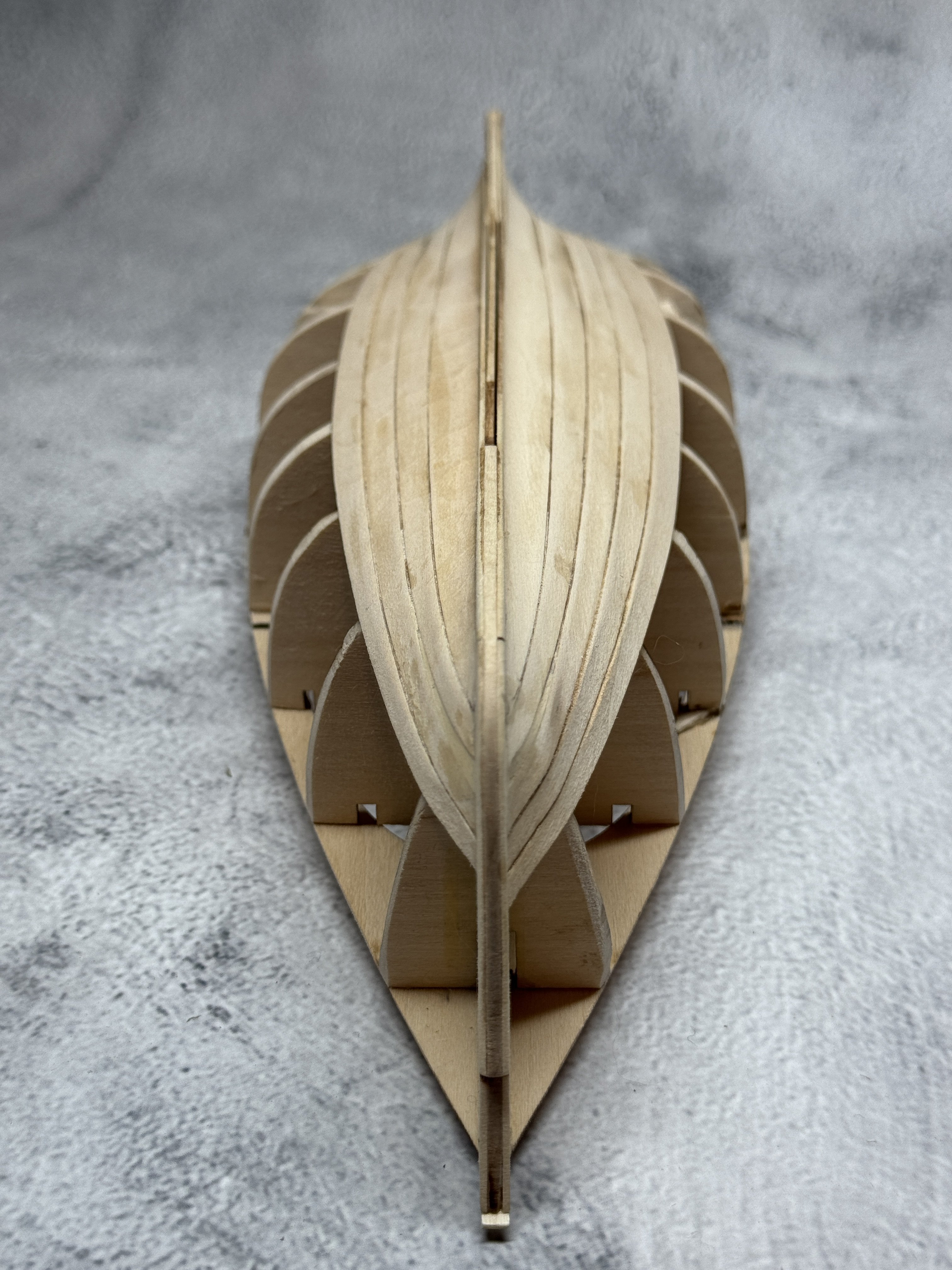
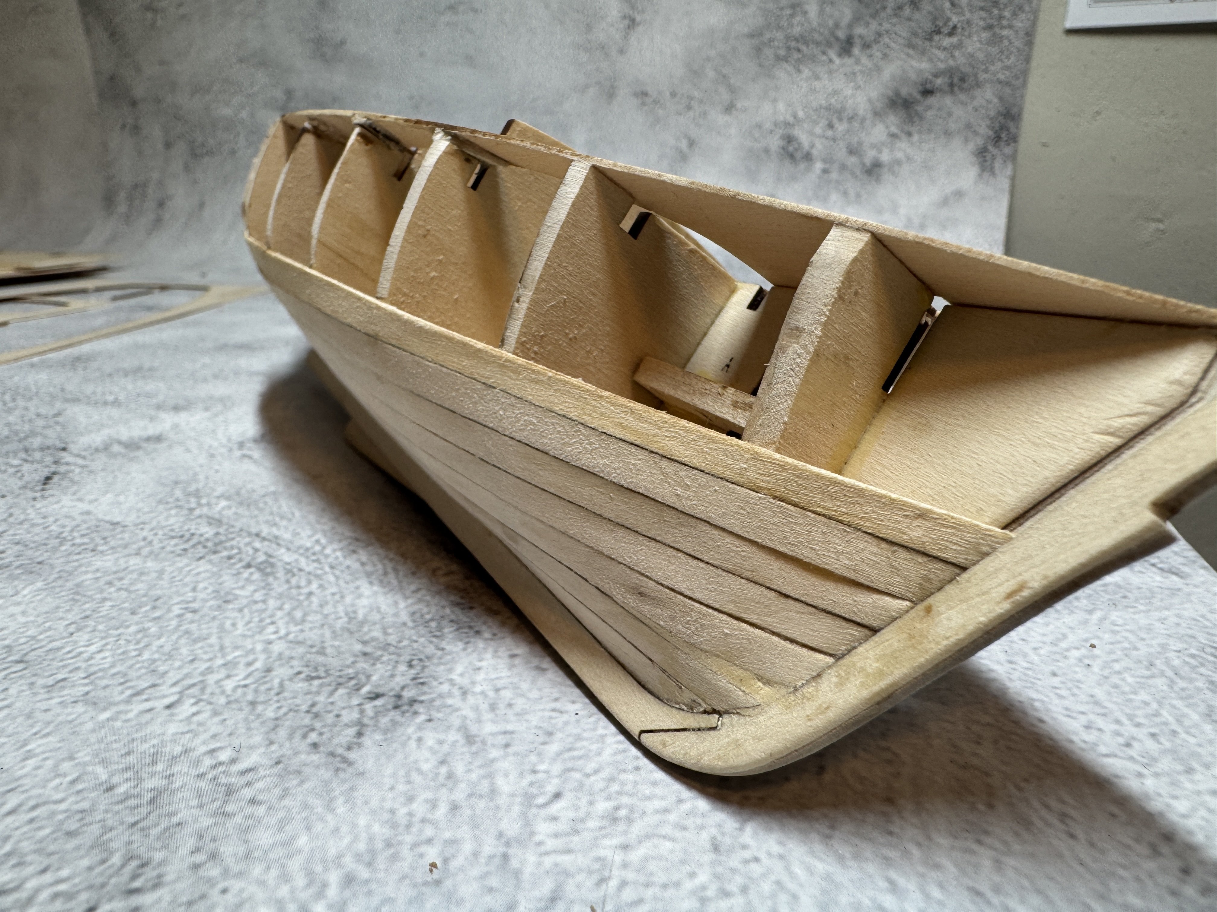
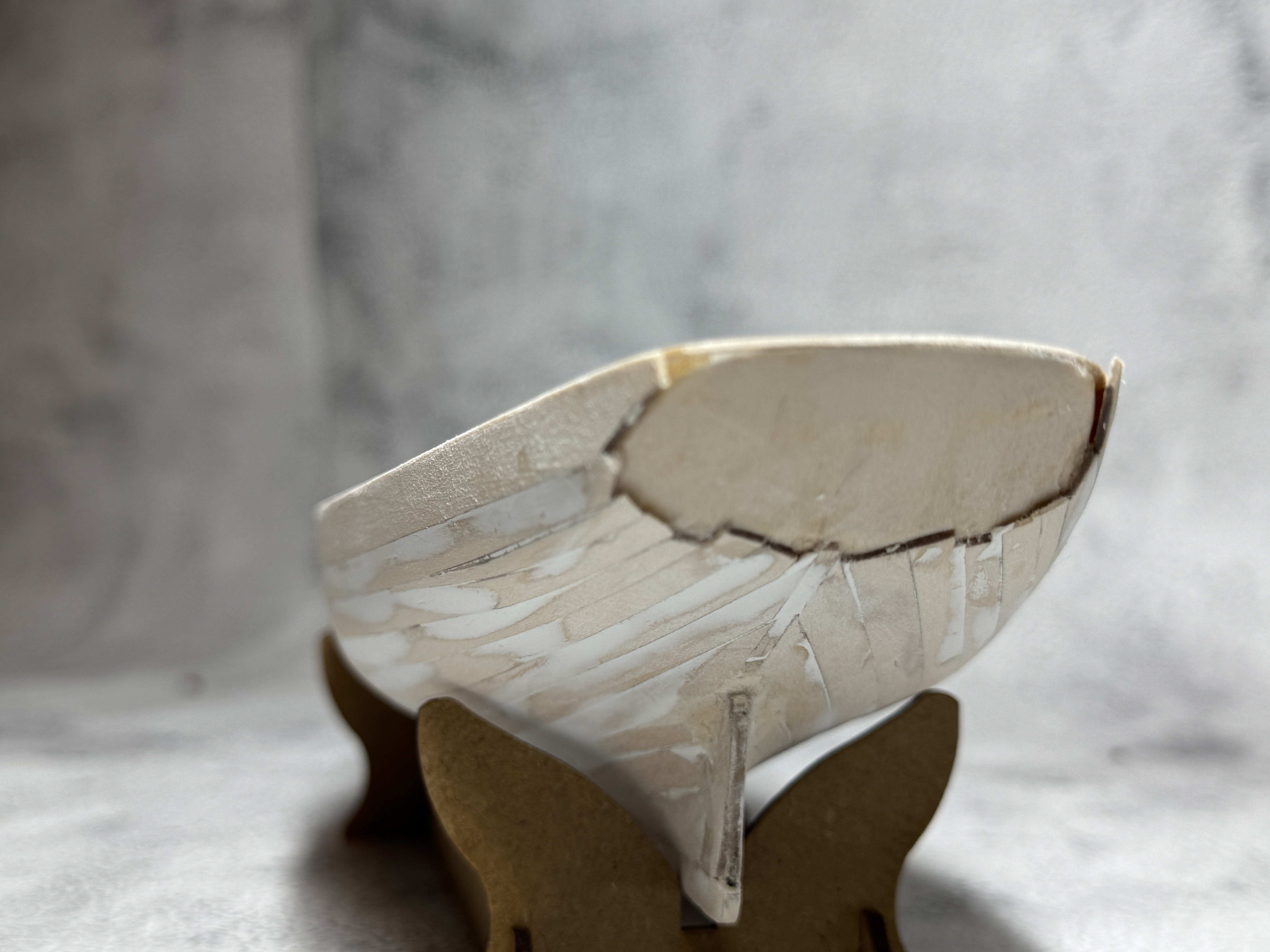
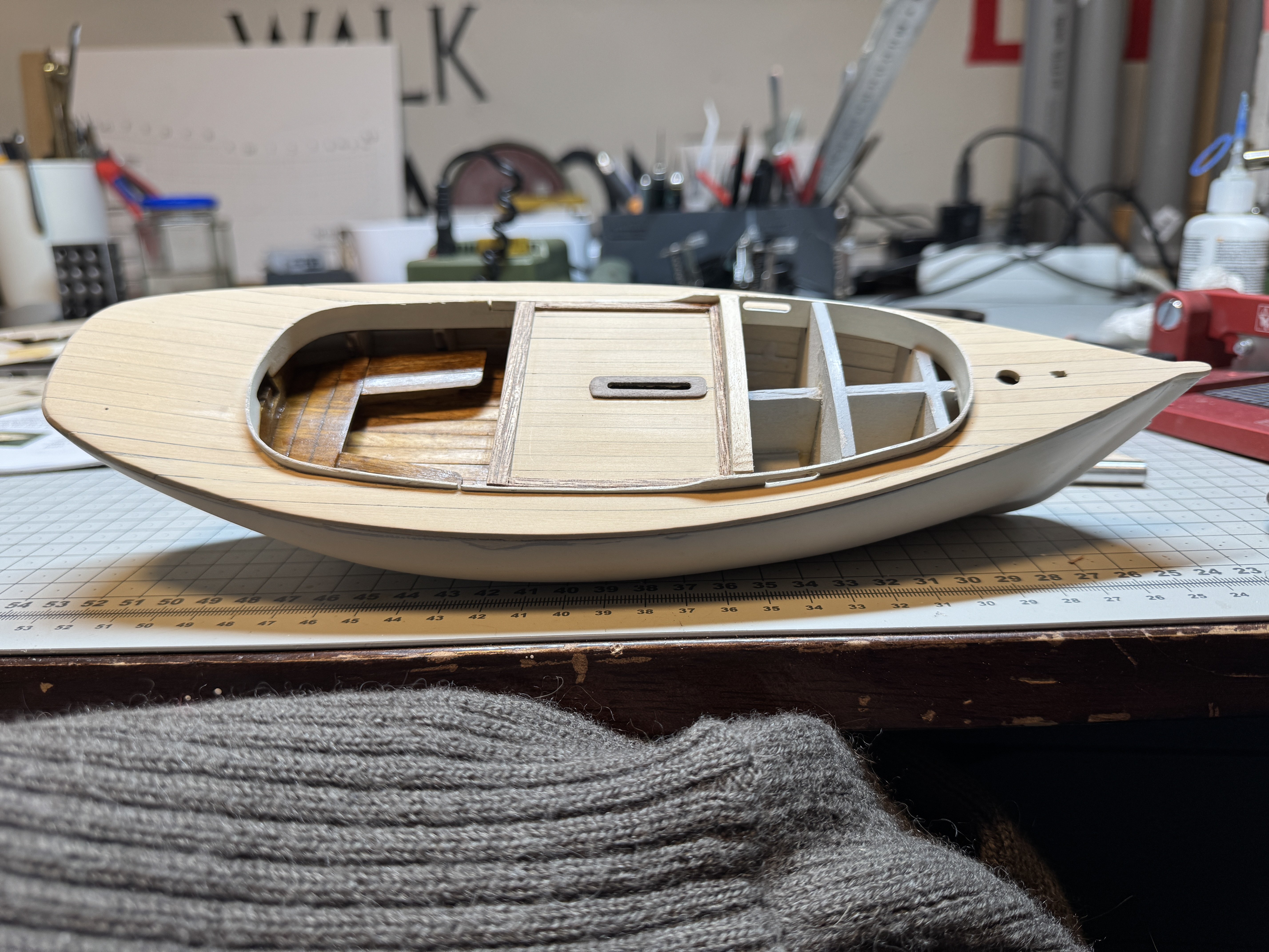
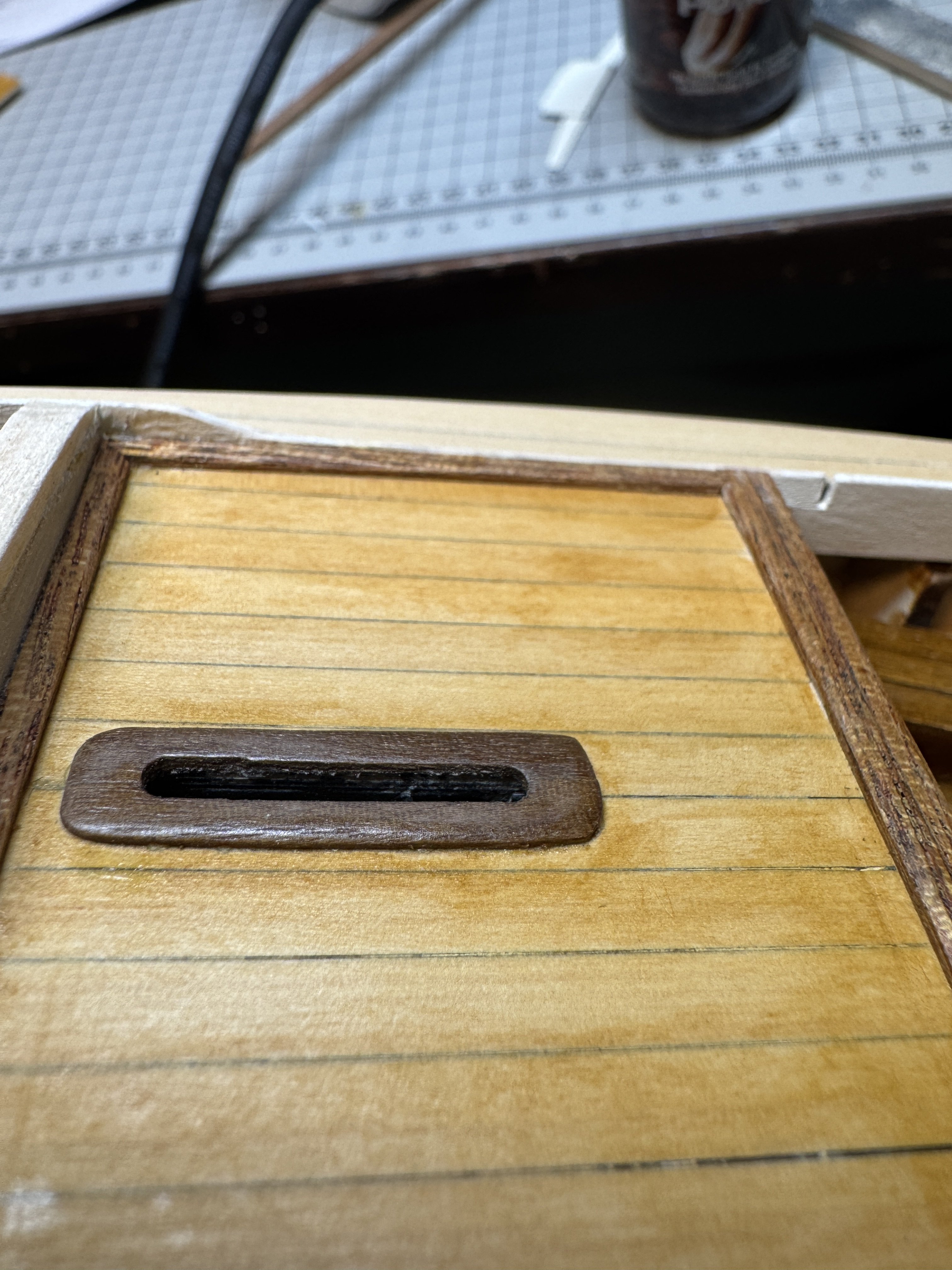
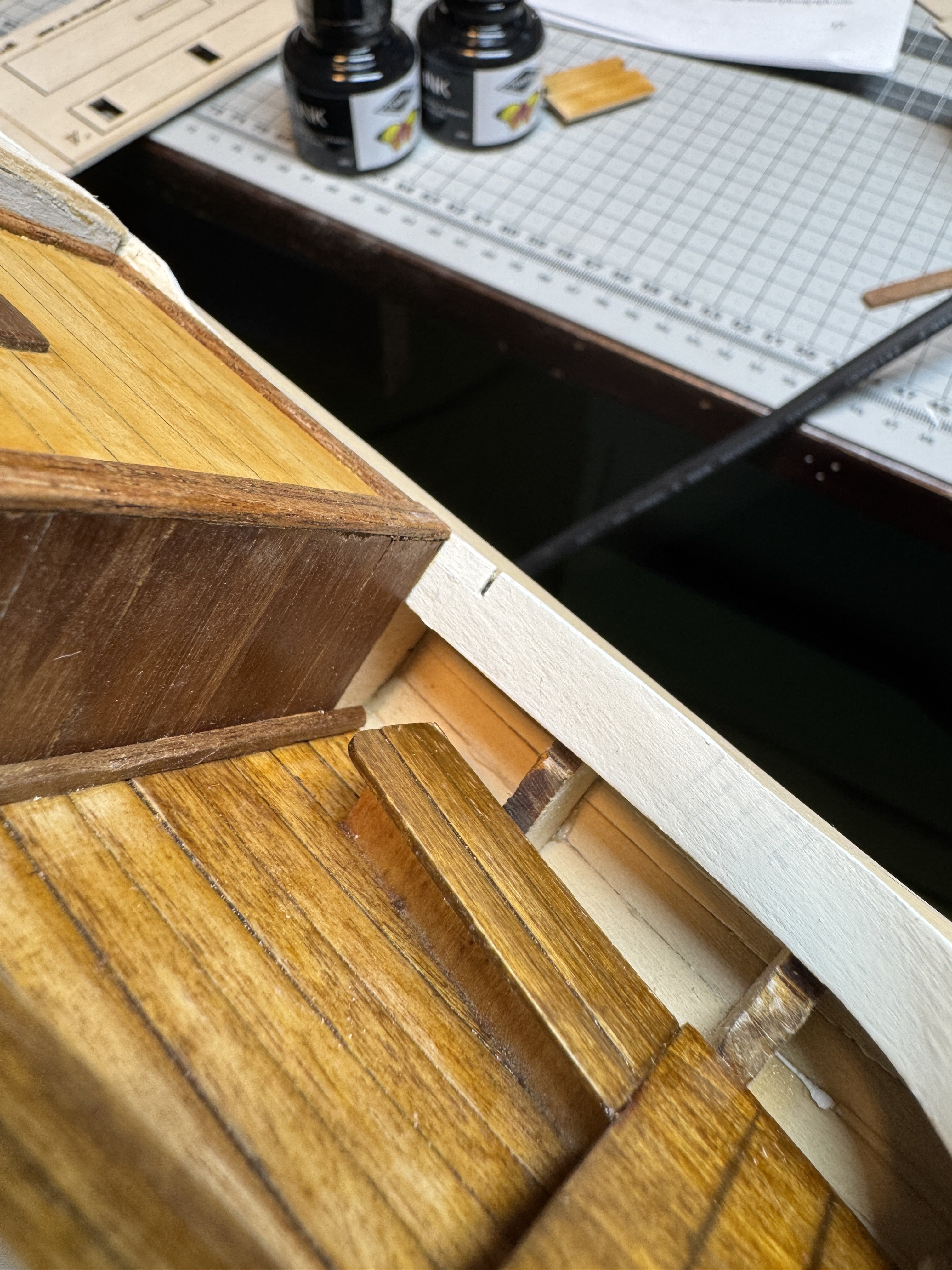
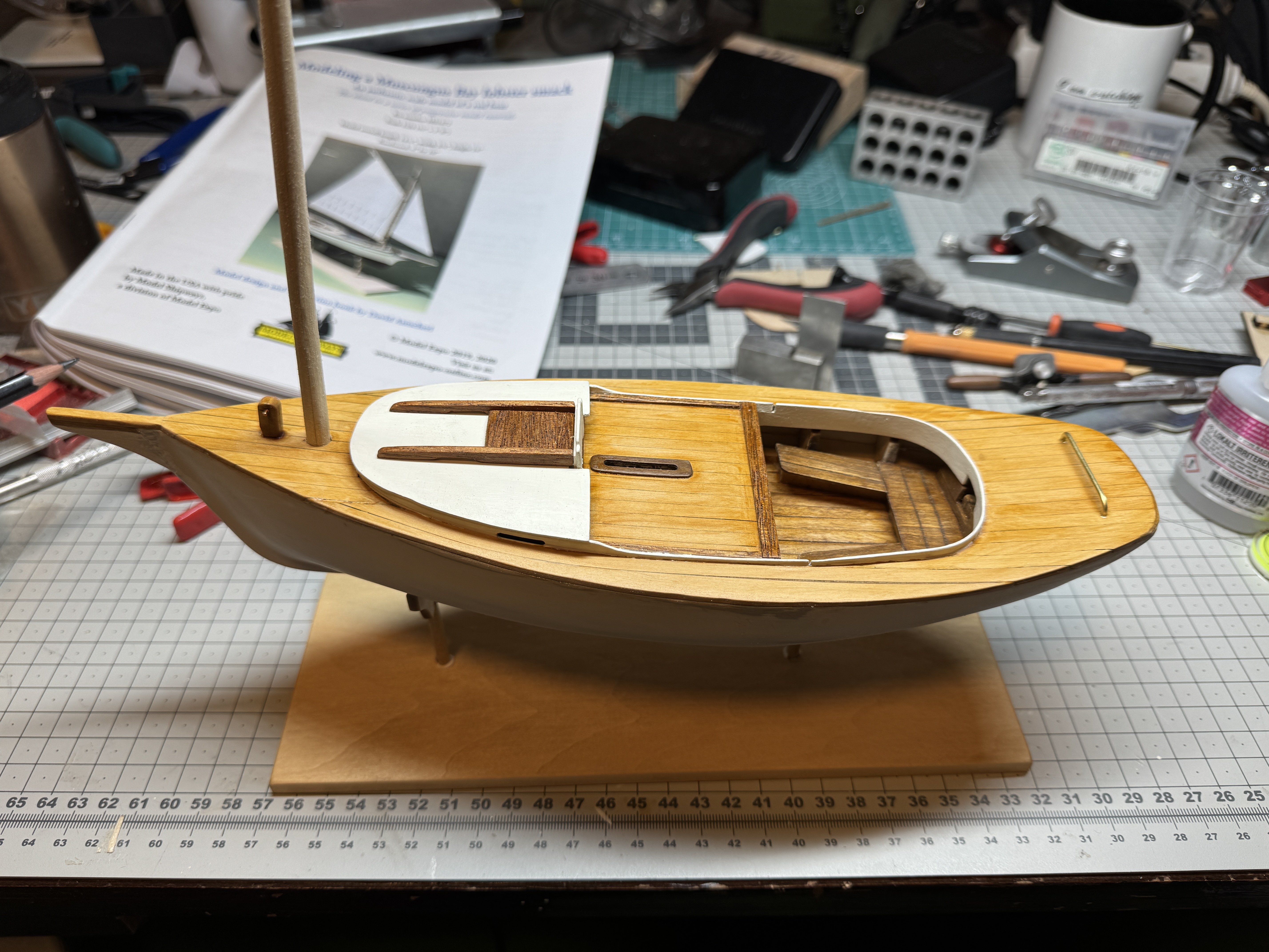
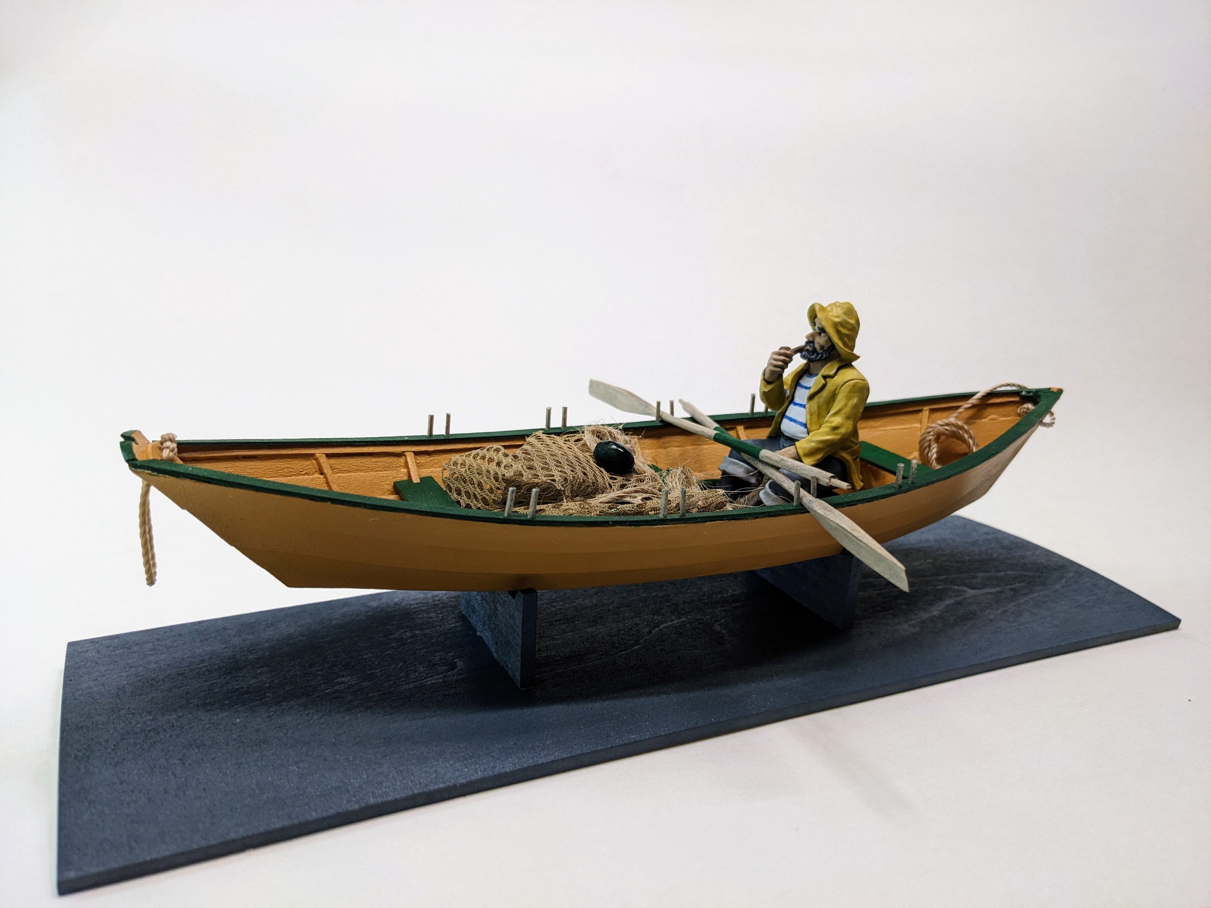
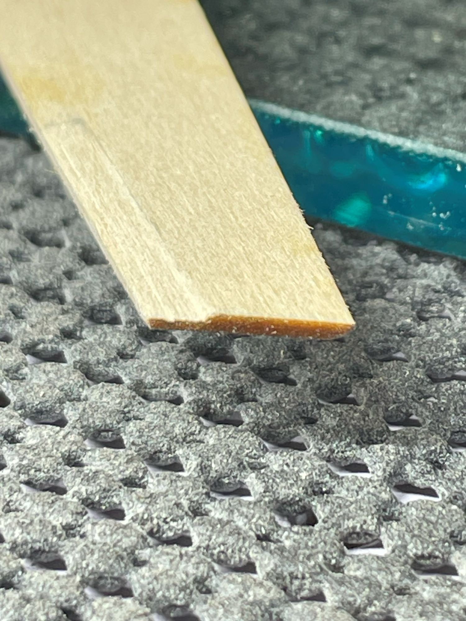
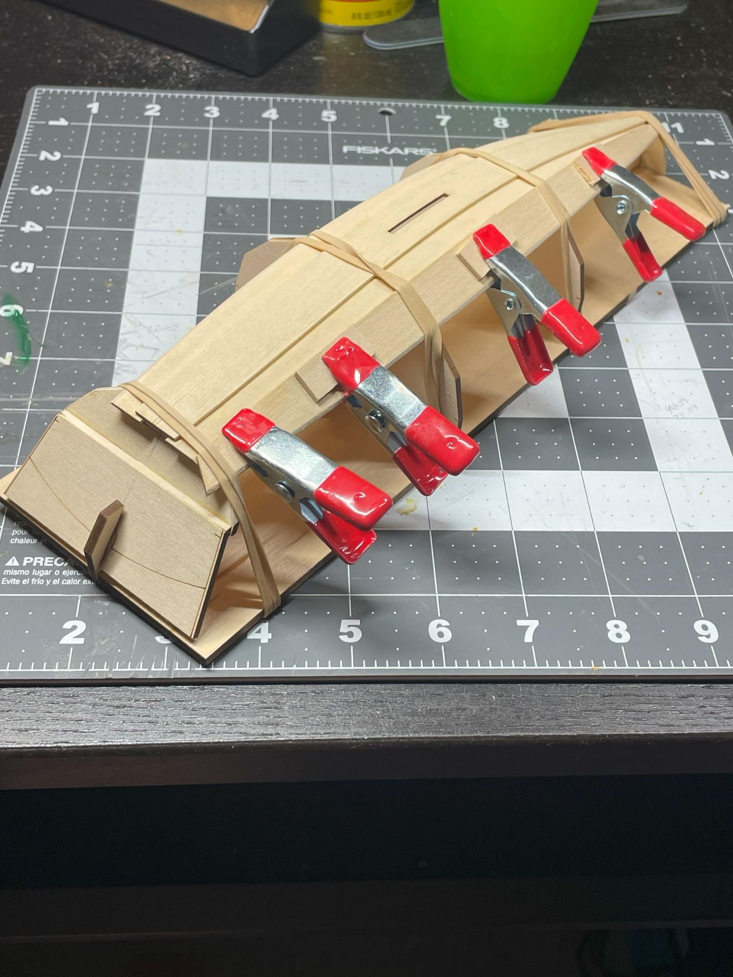
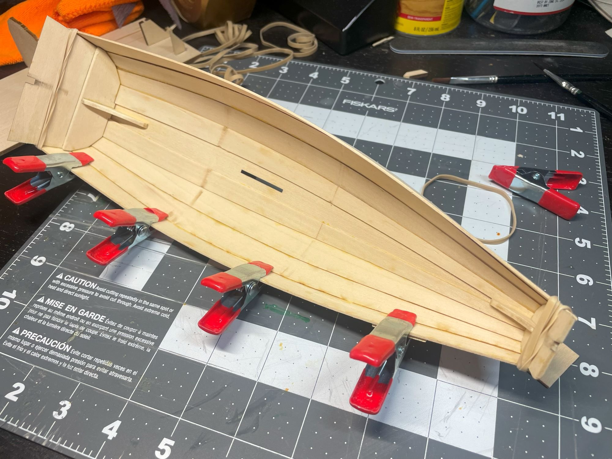
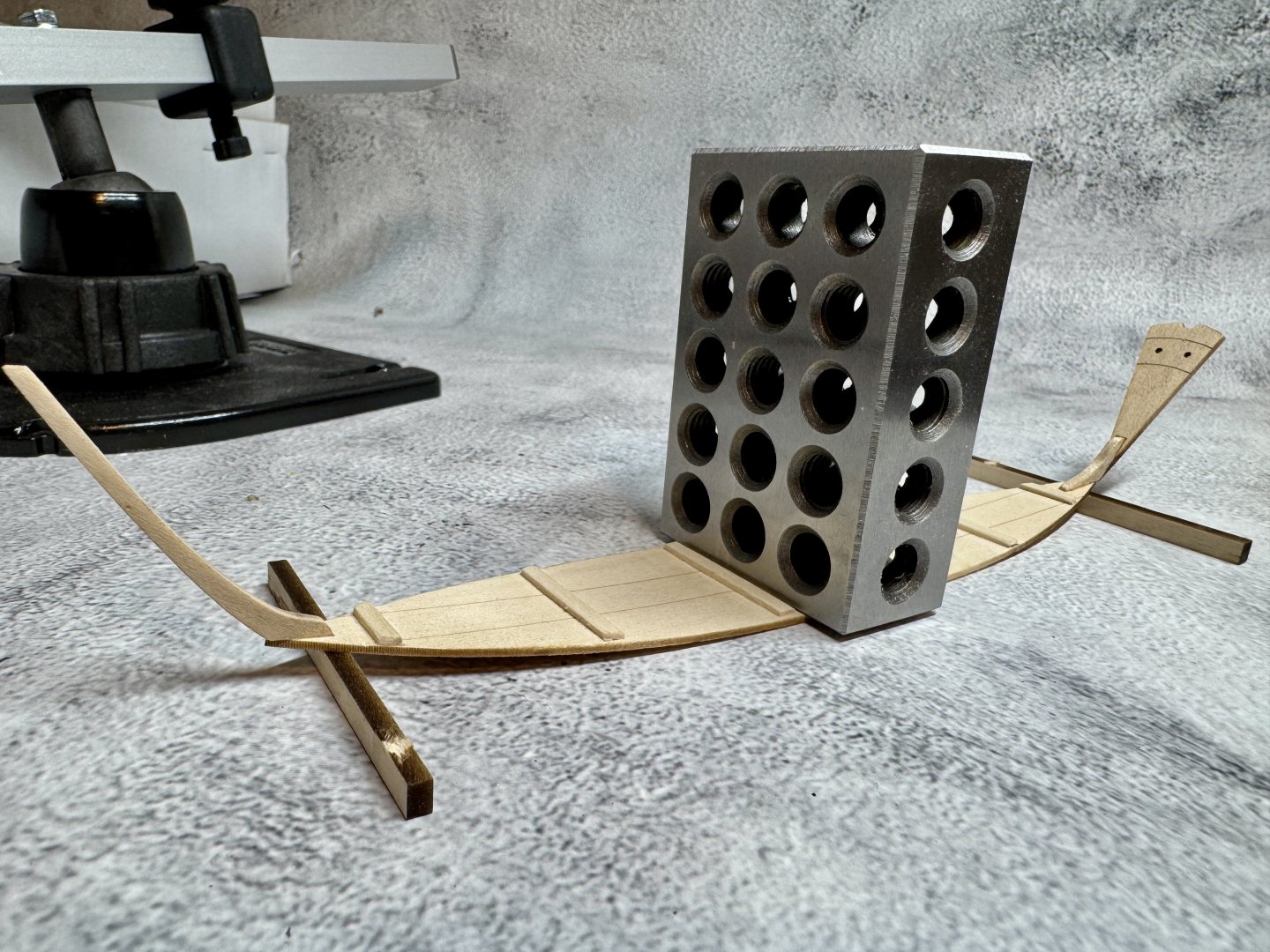
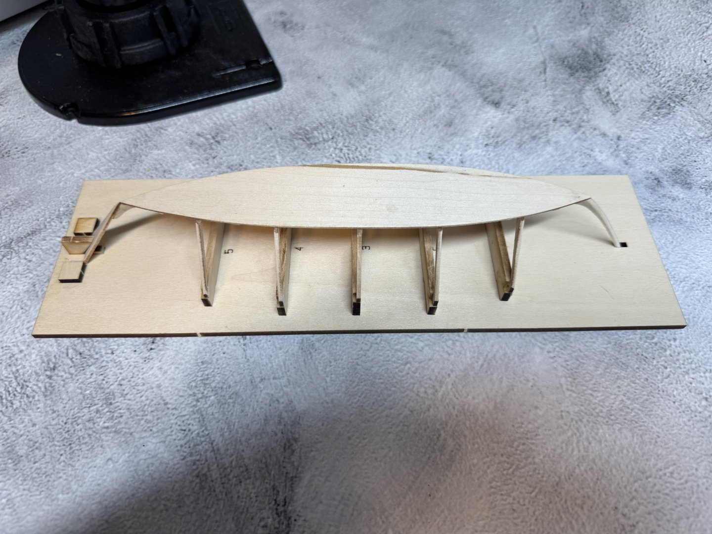
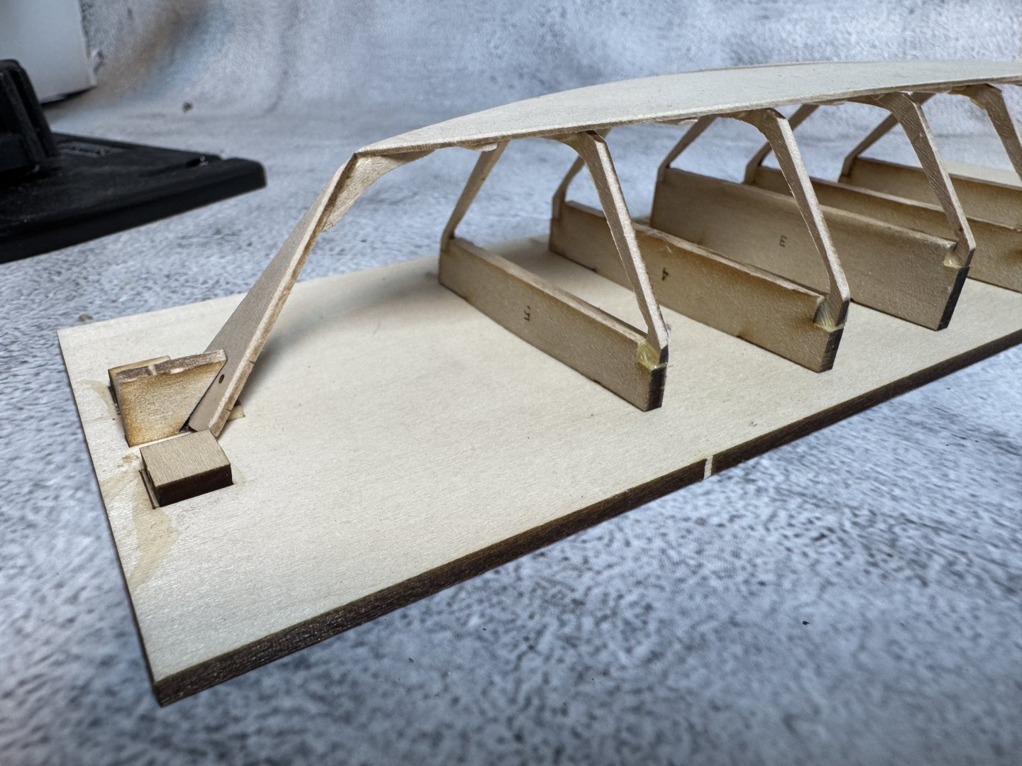
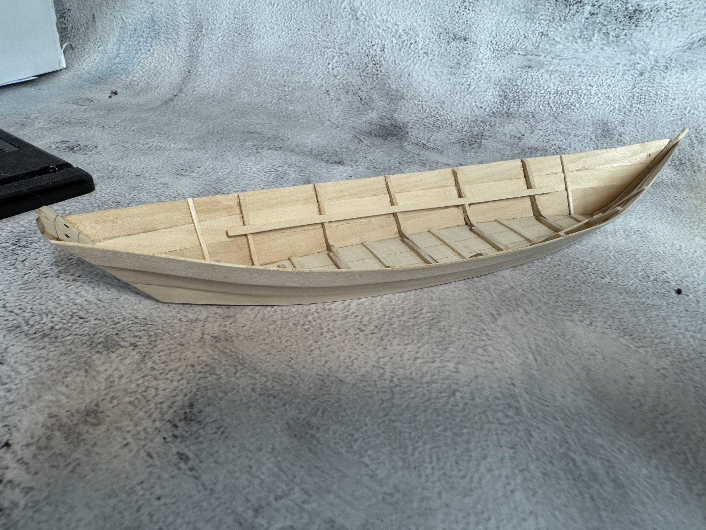
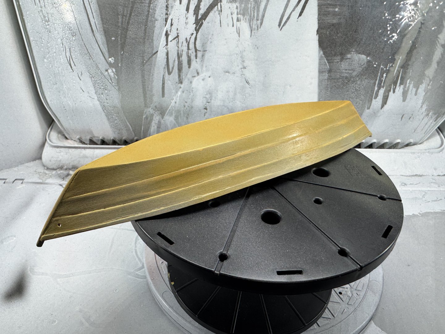
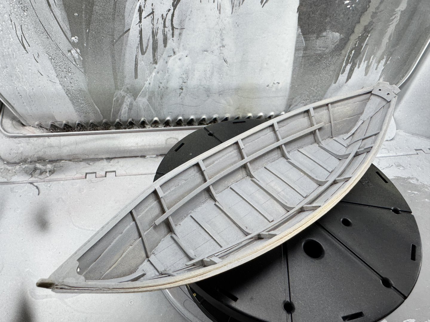
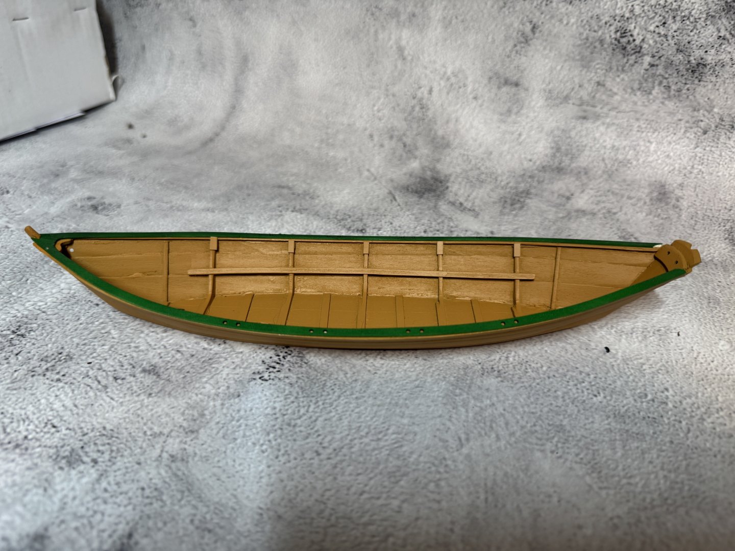
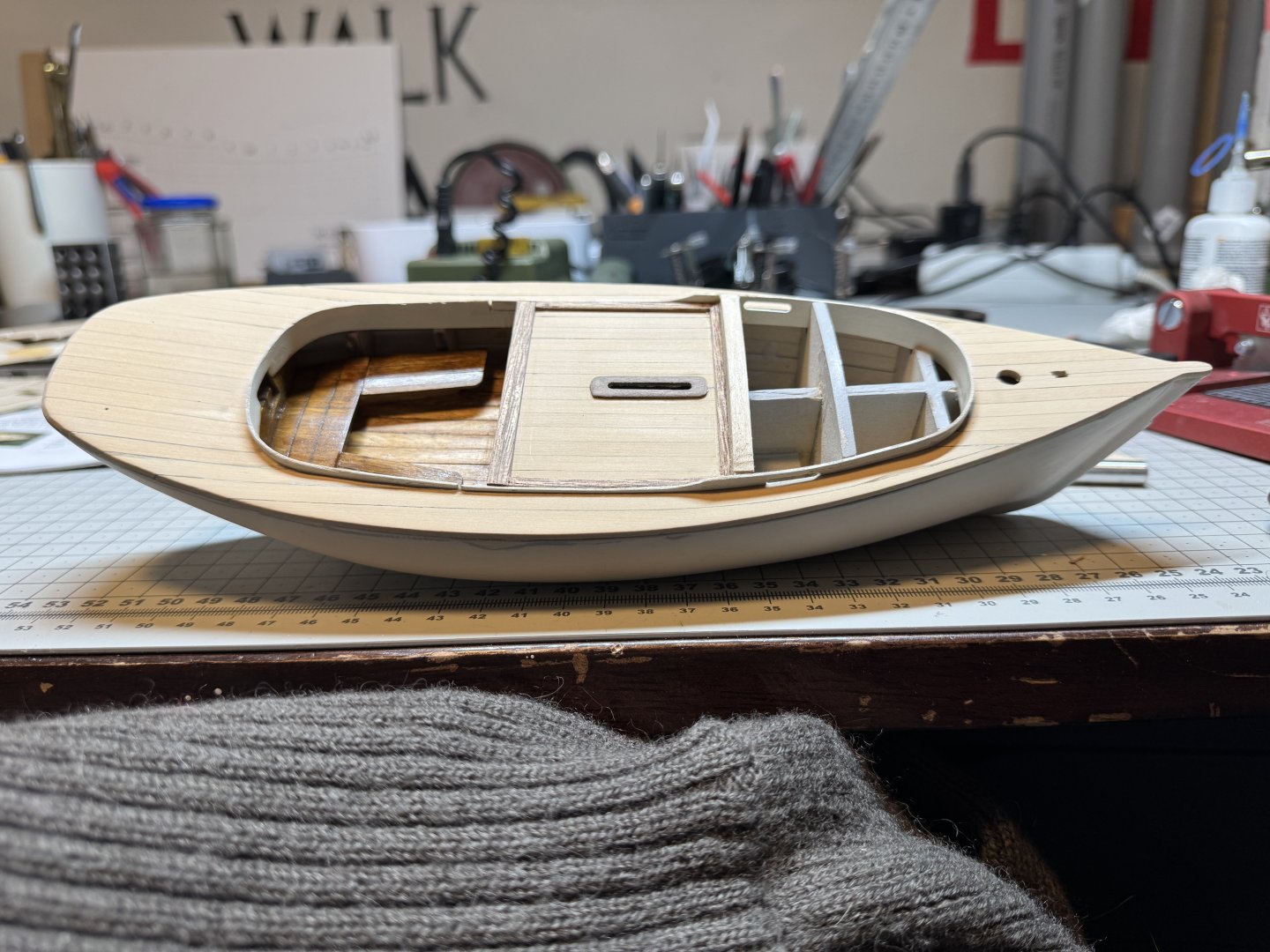
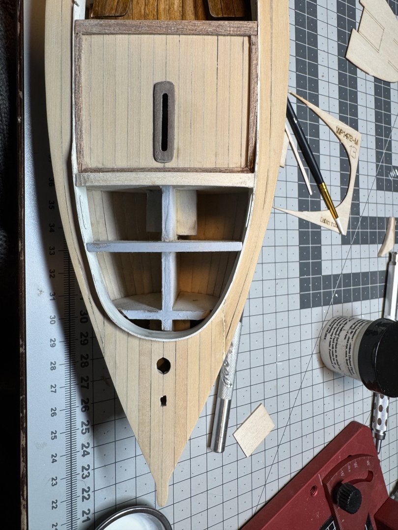
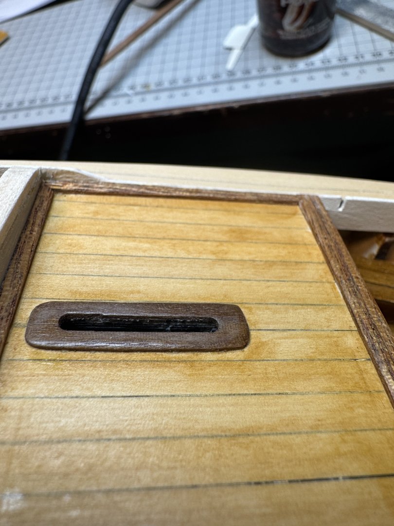
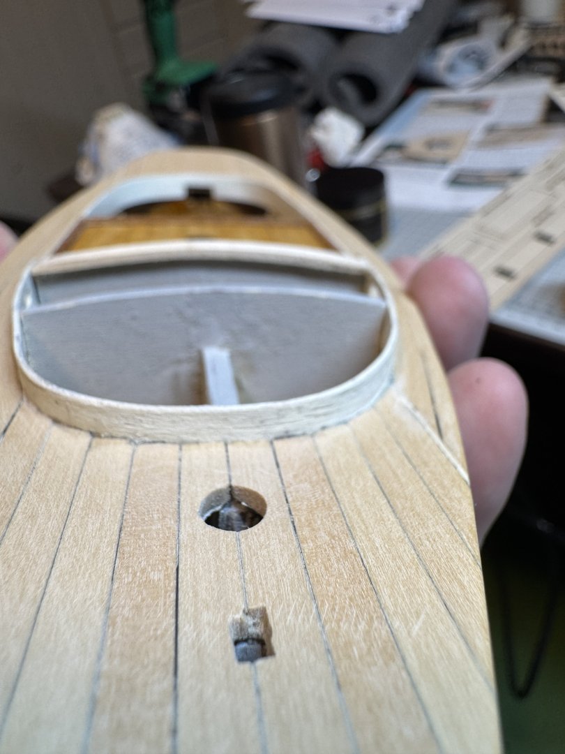
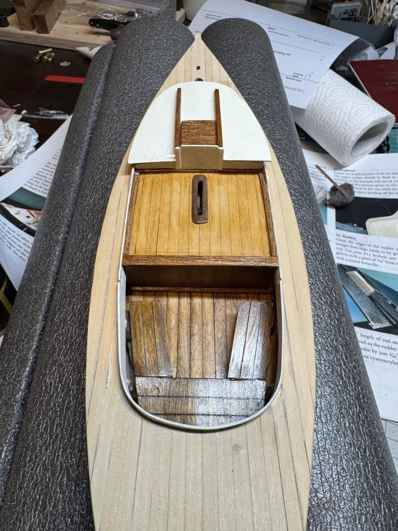
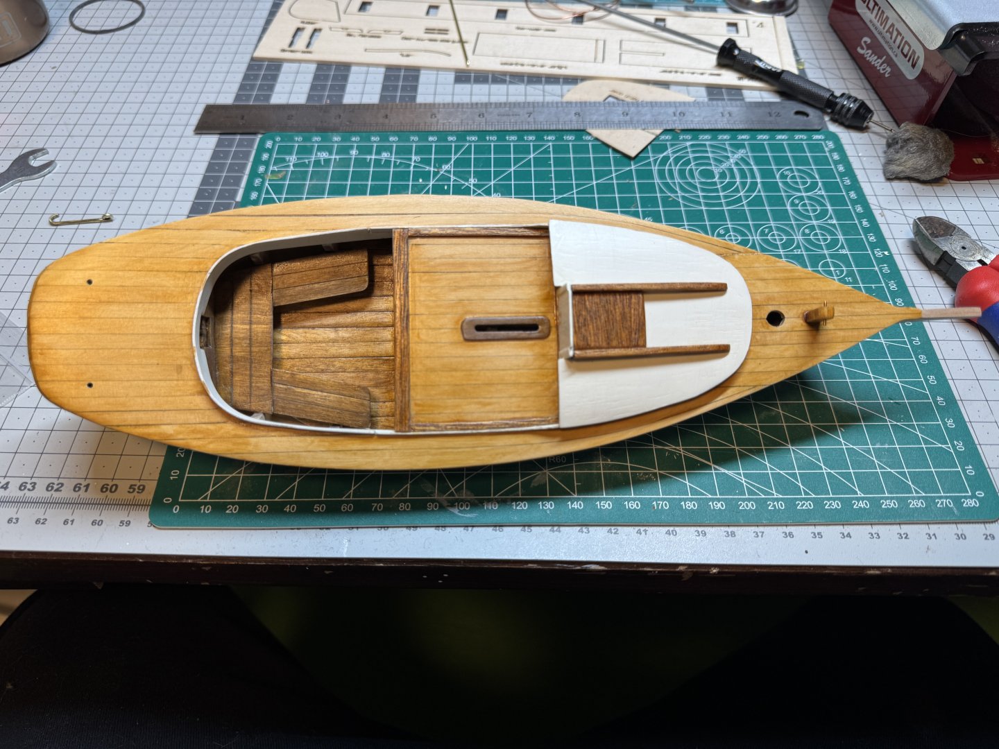
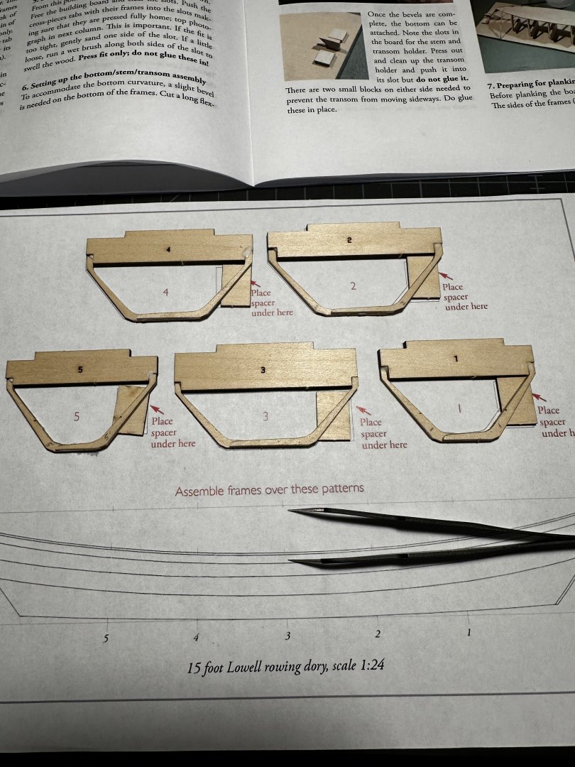
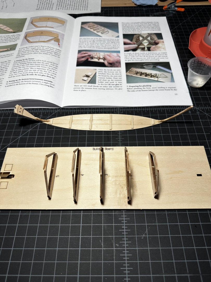
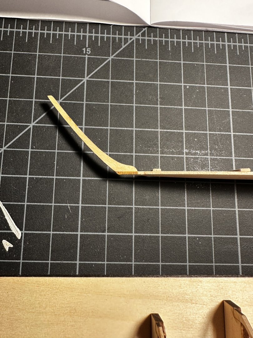
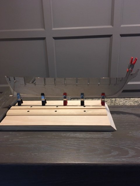
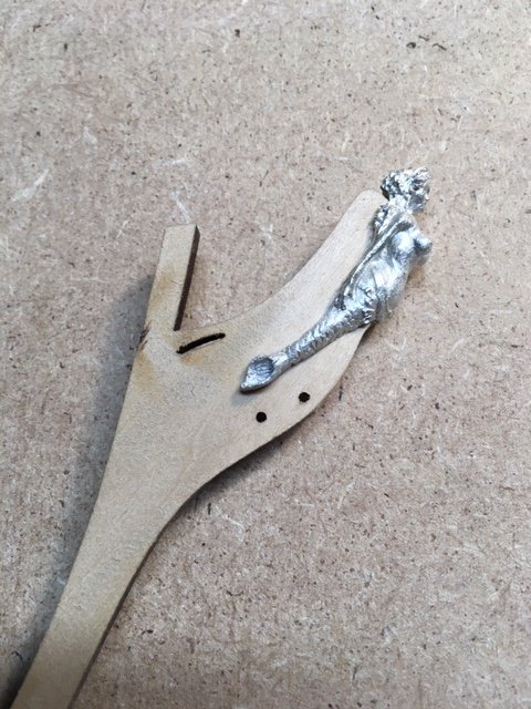
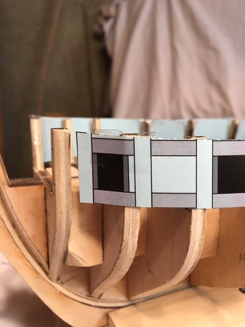
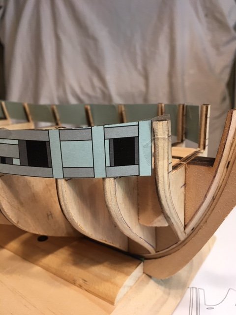
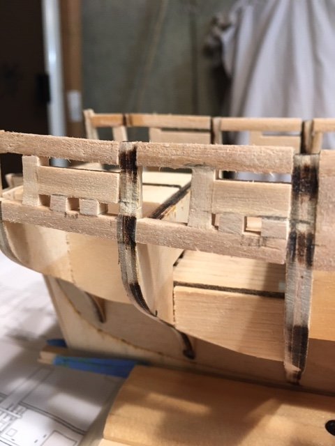
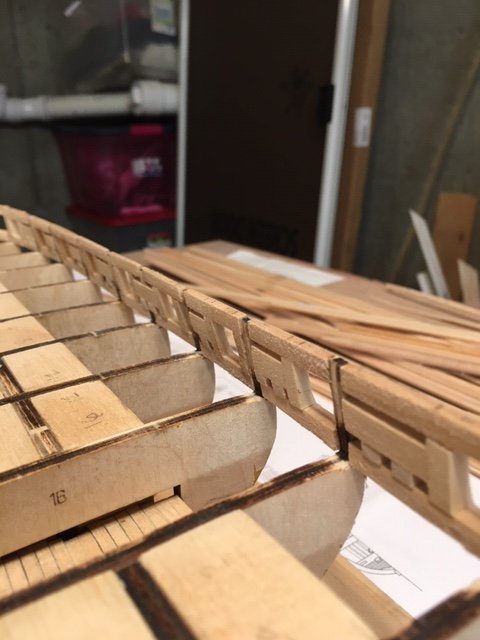
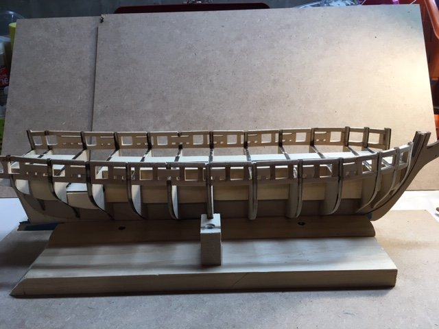
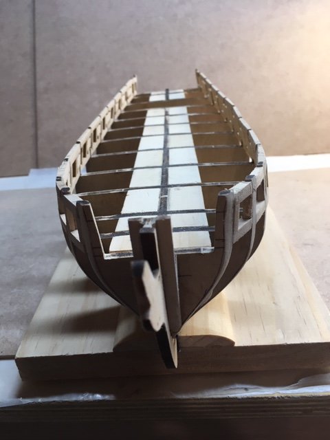
 To make progress on my Pram and Sherbourne, I needed a small miter box (to cut copper tube for the Pram, to cut masts for the Sherbourne). It came in but it turned out the narrow saw I had would not work with the miter box, so I had to order another saw. While I ordered the saw on Amazon and have Amazon Prime, it'll be another week or so before the saw arrives. While waiting, I decided to start on the Lobster Smack, the third kit in the Model Shipwright Series. Some notes and heads up on this one: - I chose to keep the centerboard glued into place. A challenge of doing so is that the centerboard then becomes an easy thing to crack or break (it’s terribly thin basswood) and it gets in the way of banding and clamping pieces after gluing. I think there’s may a 50% chance it survives the build. It might end up being in what appears to be its raised position by its absence. - This model has lots of thin basswood. That makes it easier to shape pieces (and some pieces have to be shaped quite a bit). But it also means it's pretty easy to sand through the planks when finishing the hull (I did not do that because I learned from my half hull build when I did it). - Like other Shipwright Series models, do not assume any “to scale” drawings are actually to scale (I don’t know if other Model Shipways models have the same problem). I had to zoom to around 103% to get something close, at least when I had a point of reference. It’s frustrating for the price they charge these models that they don’t have better quality control. Drawings to scale should be to scale. - I was completing the Pram and Smack before completing the Sherbourne because I wanted to get some practice on rigging before doing it on the Sherbourne. It's not necessarily that the Sherbourne is more challenging (in some way it's less challenging because the instructions and plans are so complete), but because I'd rather make a mistake on the Pram or Smack than the Sherbourne. One bit of frustration with the Smack (and Pram) compared to the Sherbourne is that the rigging instructions for the Smack are incomplete at best. I ended up having to turn to the instructions on the Pram to figure out how to rig the sails (they end up using a similar technique which is explained more completely for the Pram - so if you're just building the Smack, open up the instructions online on the Model Expo site for the Pram when you get to the rigging section). Unlike the Sherbourne, there are no rigging plans for the Smack. There is a sheet, but it's more to know how to shape the sails and part out the masts. There's maybe one drawing of a bit of the rigging (really more about passing line through some blocks), but that's it. When reading the instructions, I've learned that you need to keep track of the name of a particular line that might be tied off somewhere and named in one paragraph and then the description of where it goes might be explained several paragraphs later, just using the name of the line. Just follow the name of the line through the instructions to follow where the lines is supposed to go. I'm sure this is obvious for people with lots of experience working on boats or building models, but it's a little frustration when this is supposed to be an "instructional" model kit to have the instructions so confusing. I suppose compared to many model kits (not including Vanguard's) these are more complete than some models, so in a way if you can't get past these fairly complete incomplete instructions, maybe you won't do well on a non-instructional model kit with few instructions at all. I've seen some kits that seem to only have a bundle of material and a set of plans to follow. - One thing to make note of is that the metal - I think it's called Britannia metal (which replaced lead in old models I believe) - is pretty soft and kind of lousy. The rigging line supplied with the kit and the holes in some of the metal parts the rigging needs to go through are not quite lined up with each other (the line is way thicker than the hole). As a result, I had to bore out some holes a bit to even hope to get the line through a part. Well that then structurally weakened the metal (way more so than I would have thought given how much thickness remained). And just when tightening a piece of rigging (just a tiny bit so it didn't sag) the metal failed. Be careful. - For future builders: This kit does offer opportunities for kit bashing since some of the details are pretty basic (e.g., doors and hatches that are just square pieces of basswood with no detail at all). I thought for a second about trying to mimic some builds, but I bought the Shipwright Series just for some extra practice and I have other models in the queue I want to get to. Here’s one build that’s really nice with lots of added details someone might try to emulate: https://modelshipworld.com/topic/37380-muscongus-bay-lobster-smack-by-desertanimal-finished-model-shipways-124-moderately-bashed
- 58 replies
-
- 2
-
-
- muscongus bay lobster smack
- Model Shipways
- (and 2 more)
-
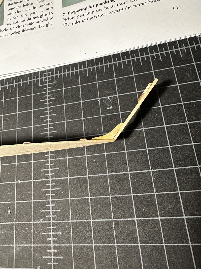
 Hello! This is my very first build of a model ship and I'm pretty happy I decided to go with the Dory first! The instructions seem to be pretty detailed but it's certainly different than what I expected... It is definitely making me learn ship part names which will be great in the long run. This is my progress after the first day... I kind of went out of order from the book and just glued most things together that could be glued so I wasn't waiting a long time between steps. A couple of the things I'm not sure about when putting together... Is the Stern Cleat supposed to be the same shape as the Transom? Or is it supposed to stick out and be used for something else (like planking)? pictured below. When attaching the Stern Knee and Stem to the bottom of the boat, it has laser etchings for where they are supposed to be glued, but it stuck way out in front/behind the bottom... I put them centered on the boat and pushed them in so that the outer edge lines up with the bottom of the boat. I appreciate any information/suggestions/help anyone has to offer me!
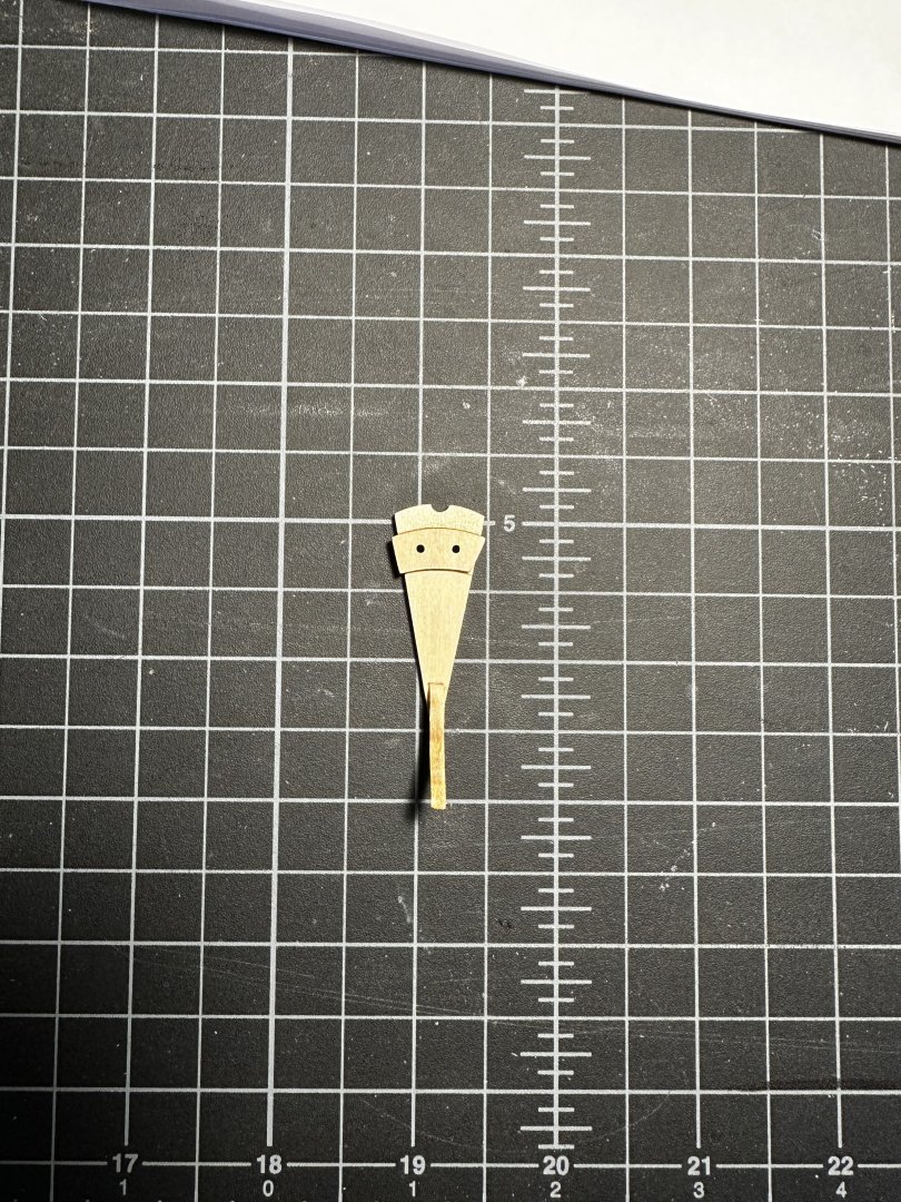
-
 This Bounty launch started as a group of friends and family members building kits at the same time. I had taken pictures along the way and thought it was worth documenting as a build log.
 -
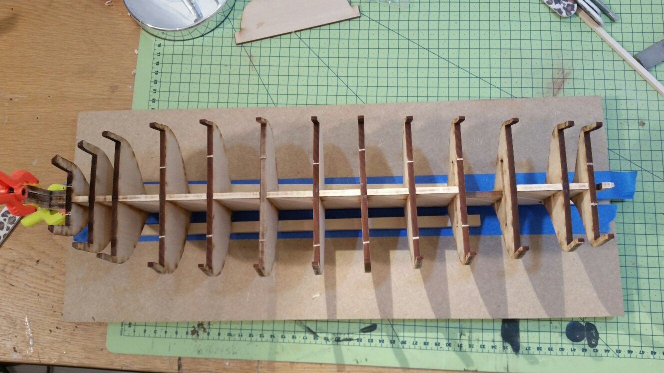
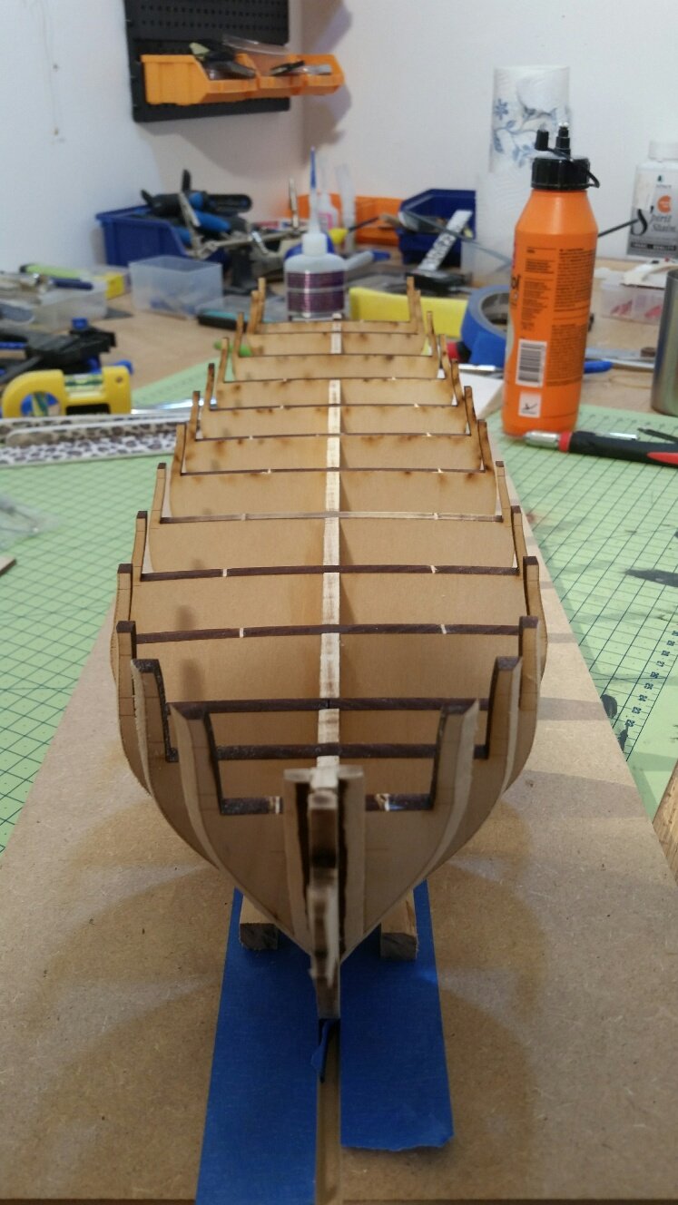
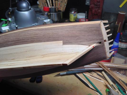
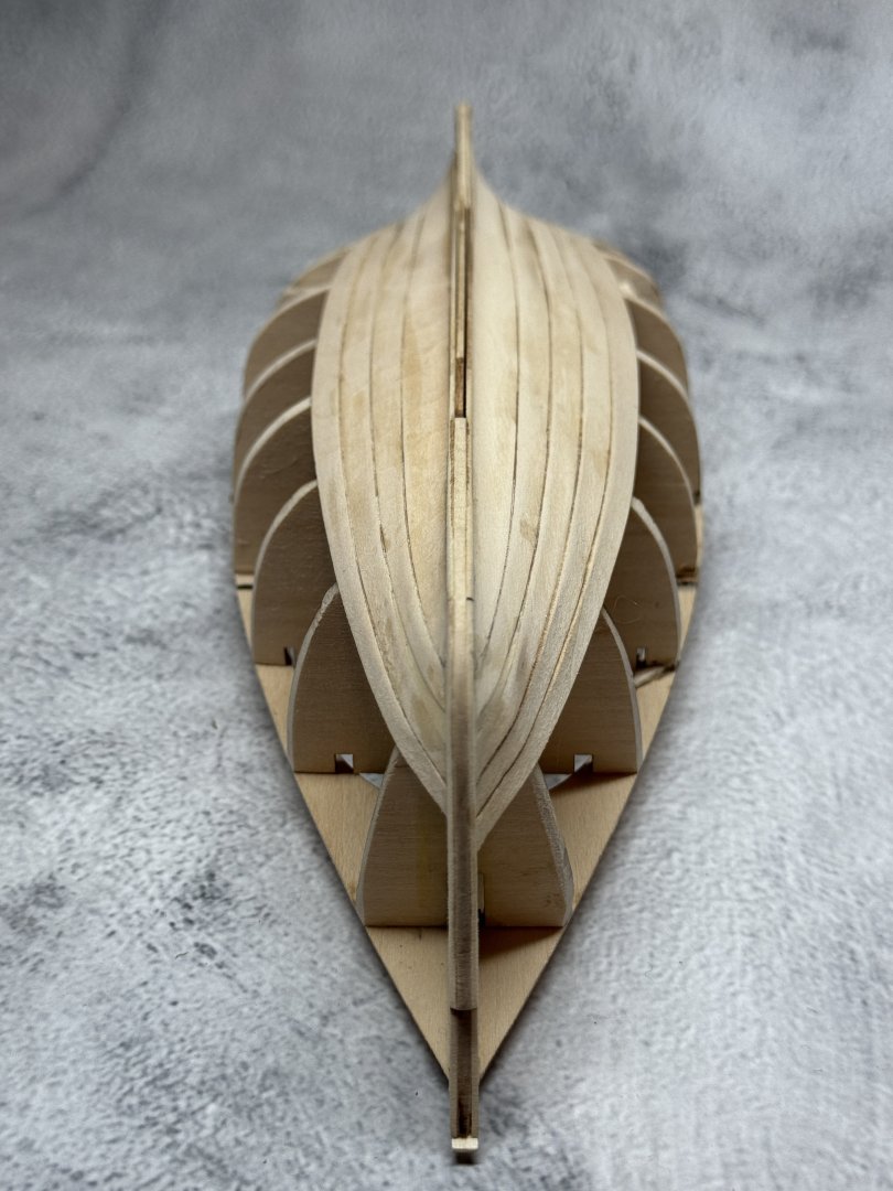
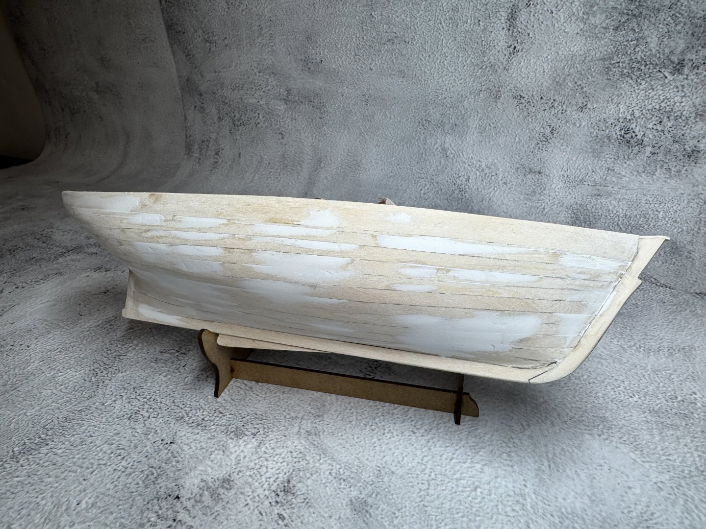
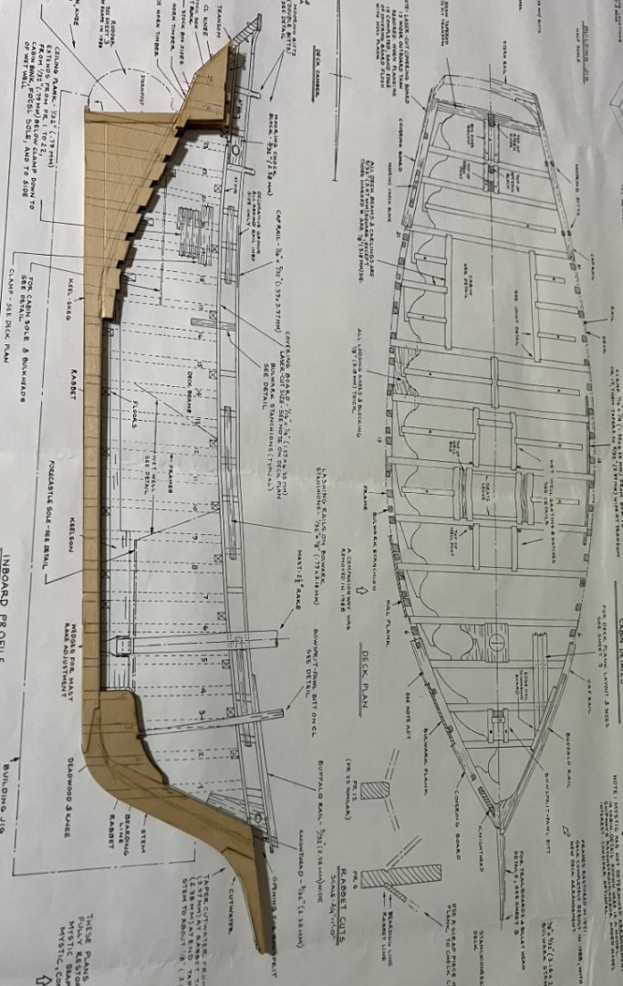
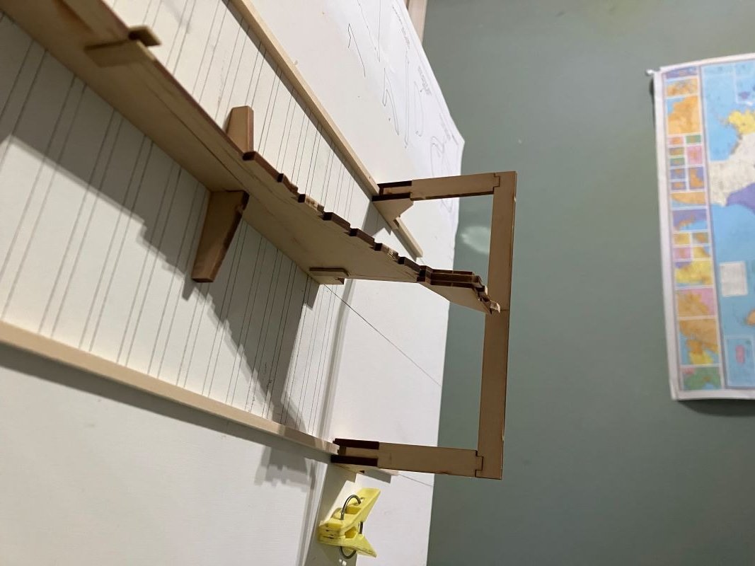
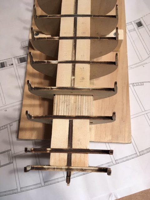
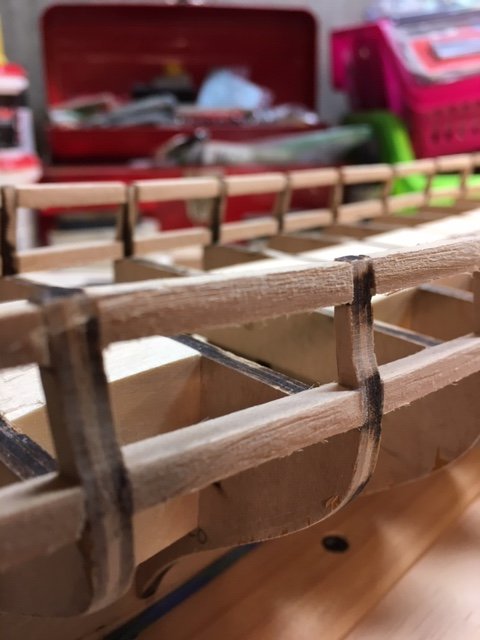
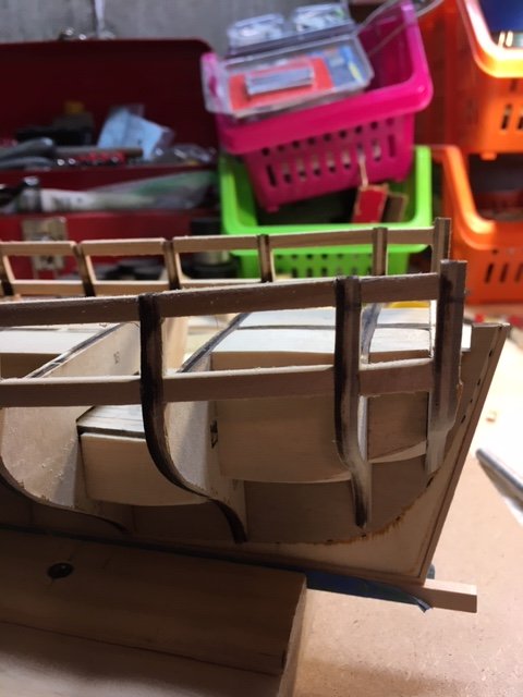
 I received this kit as a Christmas gift from my brother in 2007. That is not a typo; 2007. I wanted to finish the Rattlesnake, then I started my Coastal Pirate and all kinds of life stuff has gone by. I'm finally to the point where I'm comfortable doing this build. Thank goodness it's been patient. The instruction book mentions that a few years of her long life was spent as a yacht - that's what I'm going for. The fish well will be converted to cabin space for this build. This is my first plank-on-frame model and I really like the building jig included in the kit. I built a local skiff years ago with no jig or anything and it's shaped something like a banana. Basic start of the keel assembly: The pencil marks will be erased/sanded. The building jig: As per the instructions, the frame locations were lifted from the plans and transferred through the keel to the jig and board. It took a little while to put everything together, but time well spent up front will result in a more precise build with fewer problems. The board is a piece of straight, square, pre-primed and sealed 1 X 12. I drew the center line and marked the location for the keel support and each frame along the line. Before I glued the keel support, I used a T square and marked each frame. I built the frame clamp bar fixture and marked the lines for the strip runners on the board. I made sure it moved smoothly but stayed firm along the whole route, then nailed it down. All of this is outlined in the instruction manual - which has to be read and reread over and over. Now that everything is set in place, it all lines up just right; it's level, plumb and square. Next, I will cut the bevels in the frames. Comments Welcome, especially from other Berrys - Kenneth
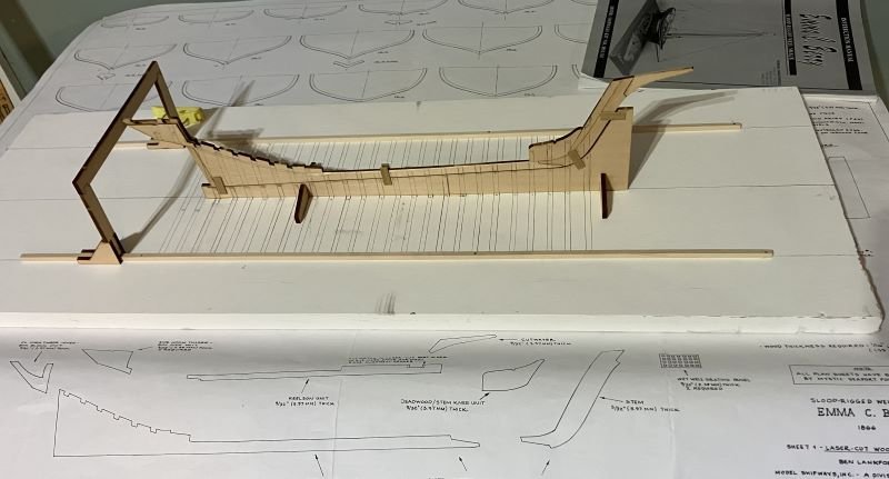
-
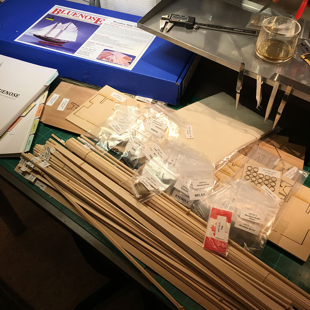
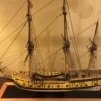 I recently completed the Fair American, which is my second build. It followed my first build– a solid hull Model Shipways Rattlesnake-that I completed 45 years ago. Looking back on the years, I had no prior ship model experience prior to the Rattlesnake. I had seen some ship models in a hobby shop, and I decided to try my hand at the Rattlesnake. IMO, the build turned out good. The 45-year hiatus was due to raising a family and making a career in civil engineering. Then, came retirement and an opportunity to try my hand at ship building again. I’m glad that I did. The experience was so gratifying that I decided to embark on a third build – the US Brig Syren. I ordered the ship from ModelExpo shortly before it temporarily closed its operations due to the Coronavirus outbreak. While awaiting delivery, I studied Chuck Passaro’s fine instructions on-line at the ModelExpo website. As I progressed through the instructions, I compared them to some Syren build logs on the Nautical Research Guild site – it helps to read other build logs and to learn from their experiences. From what I have read, I suspect this build is going to be very challenging. It’s going to test my resolve. Anyway, this is the first post on my Syren build. It starts with the obligatory photo of the ship model box. I checked the parts list against the contents and found everything to be in order. I labeled the size of the various bundled wood strips for quick reference. The numbered and lettered bulkheads (BH) were tested in their proper slots in the bulkhead former (BF). They fit nicely – no sanding necessary. The BHs will be beveled later. I soaked the 3/32” x 1/16” rabbet strip in water for about 20 minutes and then attached it to the BF, held in place with rubber bands and clips as per the instructions. After it dried, I permanently glued it to the BF, taking care to be sure that it is centered. I also glued a rabbet strip to the stern. I let the rabbet dry overnight. While the glue was drying on the rabbet, I began beveling the BHs, both outboard (first) and inboard (second). I decided to complete all the beveling before returning to the rabbet. Returning to the rabbet, I traced the laser cut bearding line and perforated holes to establish the bearding line and then carved the taper from the bearding line towards the rabbet edge. I tapered the bearding line toward the keel with a chisel and sandpaper. I completed one side when I discovered that I used the wrong size rabbet strip – Duh. So, I removed it. I decided to taper the bearding line on the opposite side of the BF before replacing the rabbet with the correct size strip. This worked out well, and it made me wonder why the tapering of the bearding line couldn’t be done before fitting the rabbet strip. For me, it was easier. You just need to taper each side evenly so as to leave a wide even plane on the bottom of the BF to glue the rabbet strip. With the taper from the bearding line to the rabbet complete, I repeated the process of installing the rabbet. I let the rabbet strip dry overnight. I turned my attention to the stem knee. I tapered the stem knee to fit the figurehead. I filed the figure to lessen the amount of taper and for her fit better. I took care not to taper the stem knee beyond the bob stay holes. I laid the BF, the stem knee, and the 3/16” x 3/16” basswood strip for the keel flat on the work bench and checked that the rabbet depth was about the same on both sides of the stem and the keel strip. I had to sand the rabbet one side to deepen the depth of the rabbet. The keel strip was fine. I glued the stem knee, secured it with clamps, and let it dry sufficiently before gluing the keel strip. While waiting for the glue to dry, I tapered the two laser cut bow fillers. I attached the false keel with blue masking tape to protect the keel. At this point, I decided to drill some pilot holes (1/8") in the BF for the masts as some other builders had done. I superimposed the BF onto the plan sheet and marked the angle of the masts on the BF using a straight edge aligned with the center line of the masts. Inserted the BHs into their respective slots, making sure that the scribed sides of each lettered BH face towards the bow and that all sides of each numbered BH face the stern. I faired the BF as per the instructions, checking the fair with a 1/8” x 1/16” planking strip. Rather than glue all the BHs permanently and then cut and glue the filler blocks, I glued each BH and cut and glued the filler blocks as I went along. I started with BHs P, N, and L, jumped to BH 26 and 24, and then completed the process from BH D through BH24. The filler blocks were cut from 1” x 2” pine stock left over from a home improvements project. With BHs and filler blocks in-place permanently, I did more fairing, outboard and inboard. Cut 1/16” x 1/8” basswood strips for the platform between BHs 16 and 20. Ran a pencil across the edge of each plank to simulate the caulking between them, and each one in-place. Opted not to add tree nails since they won’t be visible. The planks will be cleaned up and stained with MinWax Golden Oak later. Moving on to Chapter 3, I taped the framing template to the bulkheads. As can be seen in the photos, the BHs align closely with the template, except for the bow. This did not surprise me because I had read in other build logs that the templates are way off – they don’t align with BHs P and N. To check the squaring of the BHs, I cut out the overhead view template and placed it on the deck. The BHs align closely with the overhead view template. Also, as a check on my mast pilot holes, I superimposed the overhead view template on the plan sheet an marked the locations of the masts – the pilot holes are spot on. As I interpret the template, the bottom of the template represents the bottom of the 3/16” wide gun port frame. The top of the bottom yellow line would be the gun port sill. I pinned a batten at the bottom of the template on the starboard and port side of the hull. I removed the template to find that the batten doesn’t completely align with the bottom reference line etched onto each bulkhead. Considering that they aren’t that far off, and that the instructions say the bulkheads may not be sitting in their respective slots at precisely the same level, I decided to use the batten as a guide. I marked each bulkhead edge with a pencil along the top of the batten and removed the batten. The batten also serves to check the fairing. The fairing looks good as the run is fairly (no pun intended) smooth with no humps or dips. Based on the plans, the gun port sills are 3/16” above the top of the BHs (1/16” for the plank. 1/16” for the waterway, and 1/16” for the swivel bracket). So, rather than use the batten, I opted to use a 3/16” strip as a guide in locating the gun port sills. I placed the 3/16” strip on the top of the BH as a guide to align the top of the gun port frames. I think this approach should pretty much assure that the gun ports will be probably aligned with the carronades – time will tell. While waiting for Amazon to ship my Dremel 8220 cordless rotary tool, I started measuring, cutting, and fitting the gun port sill frames from the ¼” x 3/16” wood strips. I used a mini miter box for cutting the strips. Starting on the port side, I glued the frames in place (from stern and bow), taking care that the top (sill) of the frame was set flush with the 3/16” guide strip. While the glue was drying, I cut and fit the starboard side gun port frames. The ¼” wide strips require a lot of sanding – I had planned to use the Dremel. To alleviate the amount of inboard sanding, I set the frames such that they protrude just beyond the BH. The consequence of this is that it increases the amount of outboard sanding. To lessen the outboard sanding, I trimmed the frames before sanding. I sanded and filed the port side gun port frames inboard and outboard - wish I had my Dremel. Then, I glued the starboard side gun port frames, allowed the glue to dry, trimmed the frames, and sanded and filed them inboard and outboard. For the placement of the gun port lintels, I used a block cut to 15/32” to position the lintels. The process for installing the gun port lintels is the same as the gun port sills. I set the 15/32” block on each gun port sill and the lintel on top of the block and glued the lintel in-place. Whence the glued dried, I sanded and filed the lintels by hand to fair them with the hull. At this point, some the lintels are a little less than 1/8”, so I want to be careful not to over sand them. Next up, the green frames. I set up the template as per the instructions and I marked the locations for each vertical green frame on the gun port sills and lintels. I measured and cut the frames from 3/16” x ¼” stock. I glued the green frames in place using the 15/32” block as a guide. As with the sill and lintel frames, I trimmed the green frames to lessen the sanding. I sanded the outboard frames to match the BH stanchion profile. Using a 1/8” wood strip as a guide, I placed it on the port sills and marked the position of the red (horizontal) frames. I measured and cut the frames from the 3/16” x 1/14” wood strips. The frames were glued in place with the 1/4” side facing outboard – no trimming required here. I held off on sanding the red frames until after the blue frames are installed. I made a 1/8” x 1/8” block to square the sweep ports. Measured, cut, and glued sweep port frames (blue) in place. I did some final outboard sanding. The hull fairing looks good. Only one glitch so far - While sanding the lintels, BH 4 broke off. I glued it back on but didn’t get it perfectly aligned. As a result, in the last photo you’ll notice the port side of the hull has a hump at BH 4. This may not be noticeable after the bulwarks is planked and the cap rail is installed. I’m satisfied with the progress, however. Next up, Chapter 4 – Stern Framing. Stay tuned.
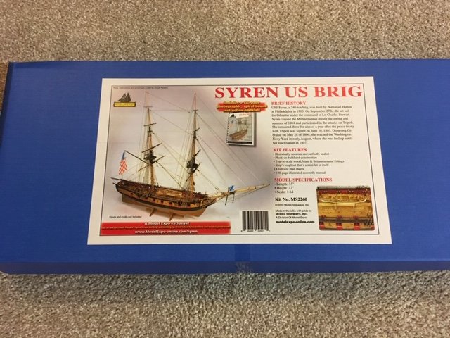
- 156 replies
-
- 8
-
-
- model shipways
- syren
- (and 1 more)
-
 I would like to introduce myself. In 1976 I was a student at a local boat building school near Fort Bragg, CA. at Abalobadiah Creek. There were four student. Two worked on a 24ft. power launch. Another student and I worked on a William Atkin 25ft. sailboat called the Gary Thomas. I was able to stay on it till we sent it to southern Cal to be sold 14 months later. After all these years my plan is to make a series of models of the Gary Thomas starting with a POB and ending with a faithful model reproduction of the one I helped build. After the Gary Thomas builds I would like to work on a longitudinal Cutaway of the Lumber Schooner Wapama. A lot of plans but I have to start somewhere so I am starting on the Norwegian Sailing Pram. I read over quite a few build logs to get an idea of the potential problems and I have found some already. I will post a few pictures tomorrow on my progress.
- 81 replies
-
- 3
-
-
- Norwegian Sailing Pram
- Model Shipways
- (and 1 more)
-
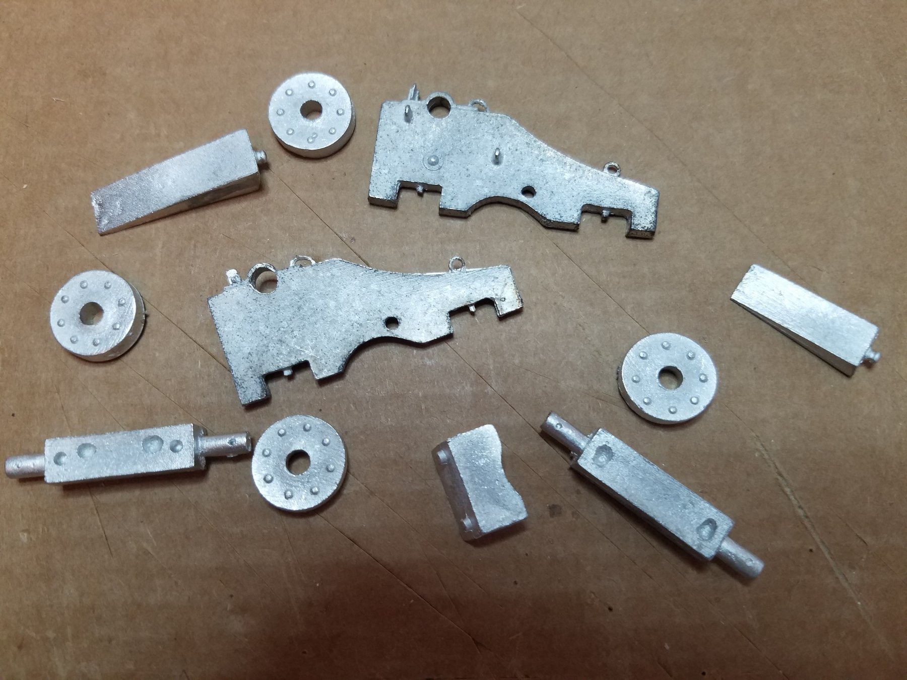
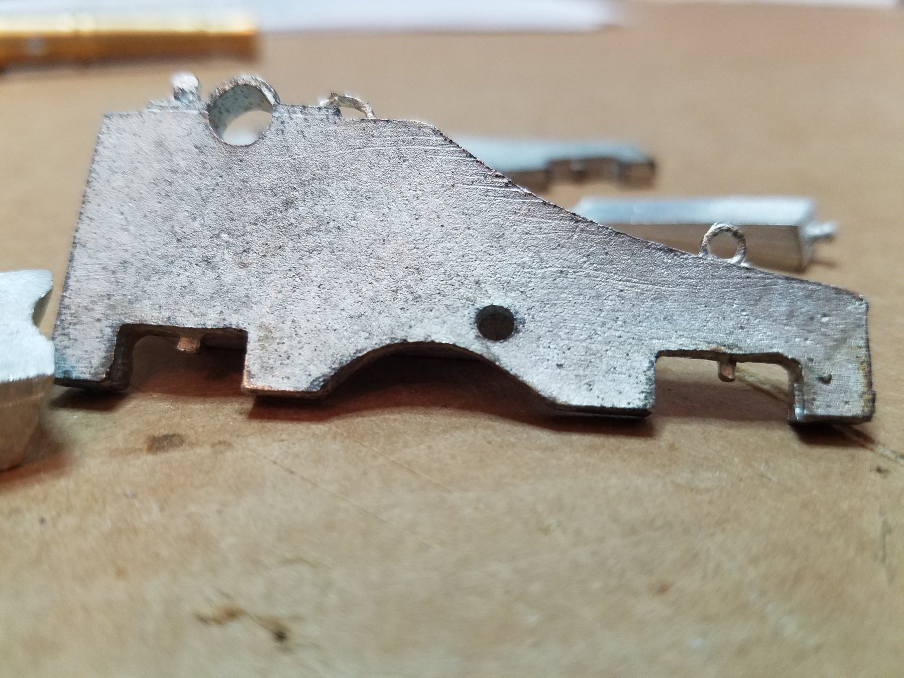
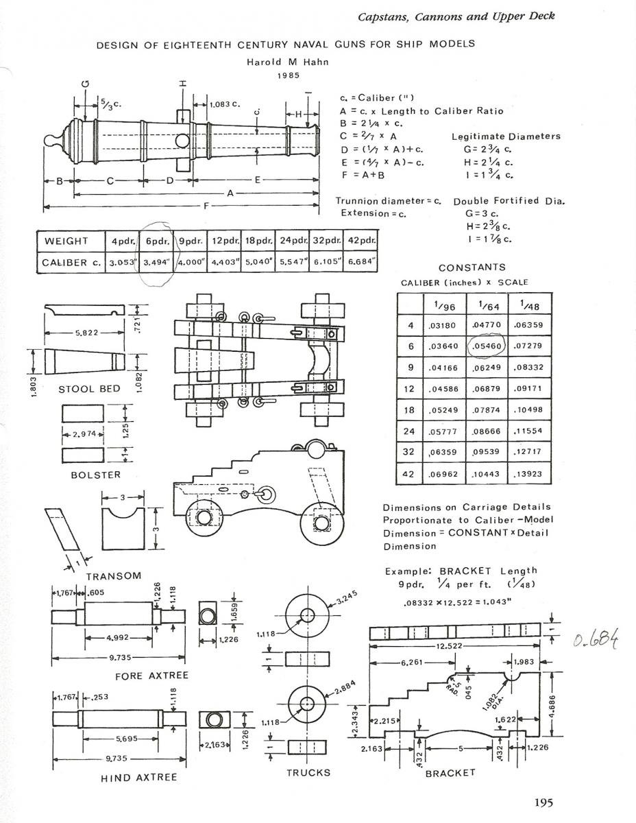
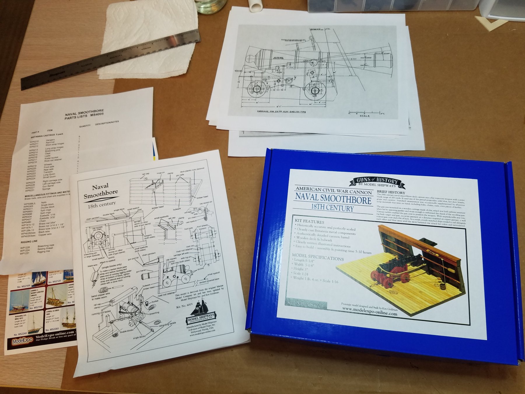
 I decided that this would be my second build instead of the bluenose. I thought this would give me a little practical deck planking opportunity as well as some scratch building/kit bashing practice as I will get into later. I purchased this kit while visiting Model Shipways a week or so ago. Where I got to see behind the scenes what goes into these kits before they go into the box so to speak. I would encourage anyone in the South Florida area to make the trip to Miami it was well worth a look. The kit itself is very complete with a nicely turned brass cannon and nice wood and cast metal fixtures, all the line, wire and chain you need is included. The instructions are not very specific written as more of a description than step by step procedure. There are enough illustrations to get the major point across though. I did not realize until opening the box that the carriage is made of cast metal and rather disappointing in my opinion. The thickness and shape of all the carriage parts is inconsistent and sloppy at best. Besides they were really made from wood weren't they. So after doing a bit of research and some quick calculations I was able to come up with what I think will make a nice replacement carriage. Using Harold Hahn's publication as a guide and after determining the real world size of the barrel as 8-1/2' and that the size of the included carriage parts most closely resembled the 12 pounder I decided that is what I would go with. So then it was just a matter of spending a couple of lunch hours reverse engineering the barrel converting the appropriate dimensions according to Mr. Hahn and drawing up a new carriage. Here is what I have so far I will finish the drawings and make a dimension set on Monday. By the way I made the 3d model in Inventor so if anyone has access to a laser cutter and wants to build one of these I would gladly trade the files for a couple of laser cut sheets. Cannon.pdf I am not sure if this will work (PDF) if not I will save it as a jpeg on Monday. in the mean time iI am off to the workbench. I will update you as work proceeds.

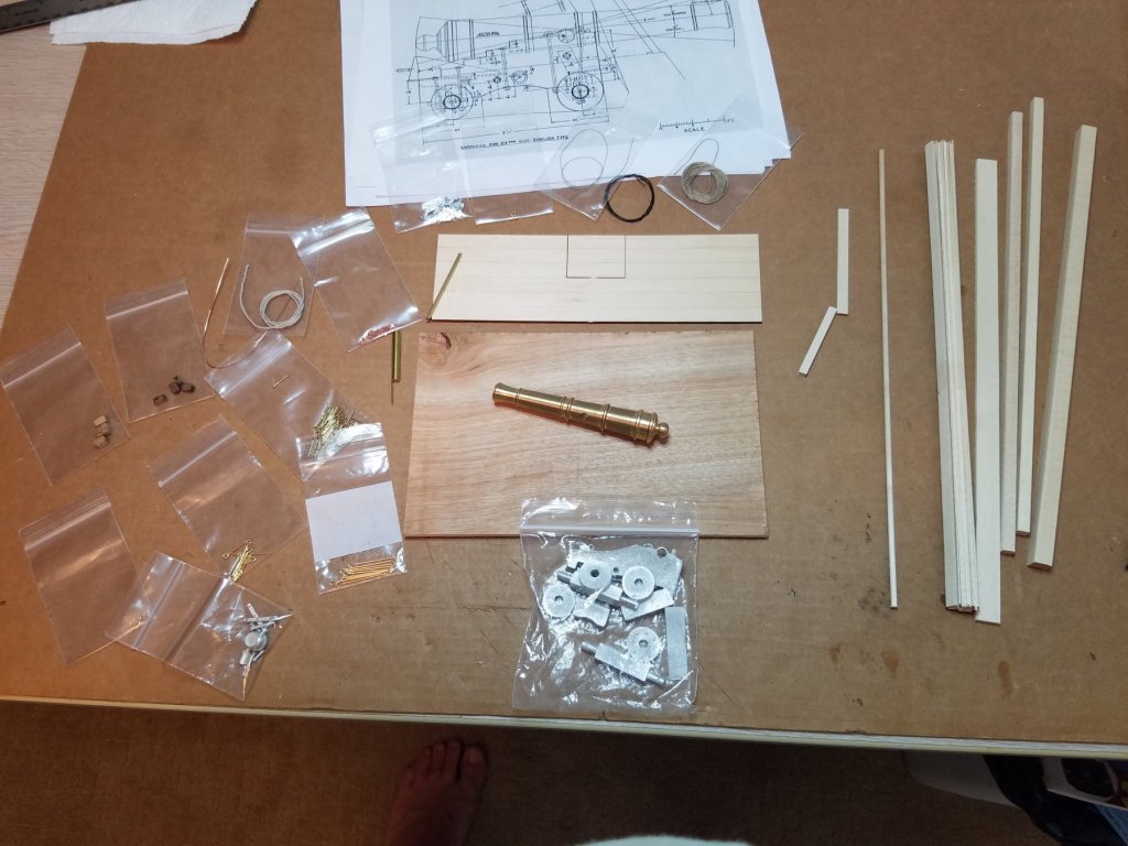
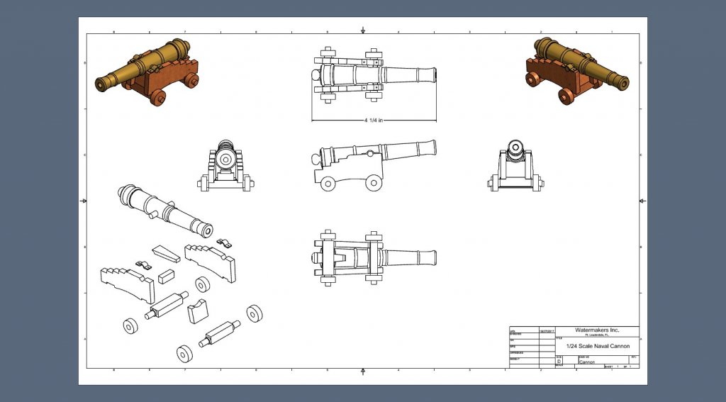
- 82 replies
-
- 9
-
-
- naval smoothbore
- model shipways
- (and 1 more)
-
 Yet another Pram build My adventure into wood ship building continues. After completing the Dory (sorry I did not find you all in time to make a build log); It was time to start the Pram (this time I will do a log haha. Early stages and just getting started. I do stream on twitch when I build so if anyone cares to check it out, you can find me over at BartBandy - Twitch
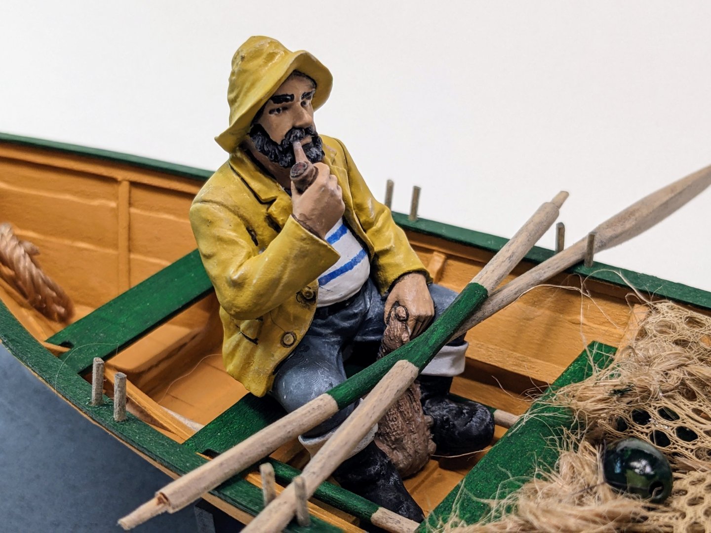


- 39 replies
-
- 8
-
-
- Norwegian Sailing Pram
- Model Shipways
- (and 1 more)
-
 Here we go on the next build the Sailing Pram. This is my second ship build. So far I am up to cleaning up the outside of the hull. I figured it was a good place to get the log started, plus I have some questions. This kit certainly has you up your game. You've got keep a close eye on many things for it to stay true. Let's start with a picture of the transom. I was a little mixed up because the knee on the aft transom reaches higher up than it does in the photos. I checked some build logs and they matched mine so I moved on. Getting everything cleaned up and ready to plank. I didn't have a lot of confidence in the the frames staying square so I added some supports. The transom mount on the base also allowed it to rotate a little so I added the other support you see in the front right of the photo. I don't have a photo of it but drilling the hole in the bow transom knee went well. I started a little smaller and slowly. It came out clean but it's just a tiny bit off center. Darn close though, I'm happy with it. Lining up the center plank. Cutting the sloping rabbet on the back of the plank for the fit at the transom. That was an exercise for sure. Tried many methods, files, sandpaper, finally resorted to more or less "shaving" off the bevel with a sharp #11 blade. And the instructions say 1/3 of the thickness of the board, Hahaha. I went a little deeper because of the overhang, no point in the end being 1/3 deep if it gets trimmed off and farther back it's not quite as deep. That's why it's a little deeper. They did improve the more I did! Somehow when sanding the bevel on the aft transom I lowered the height of the notch at the center so after the center plank was attached the transom knee was hanging in the air. I added a sliver of wood underneath neat after tracing the shape of the spare transom knee they provided. It should look ok after some cleaning up. Planking... My notes on planking. This boat planks up slowly. Getting the planks where they are supposed to go and keeping the hull flat on the forms and the transoms level with the board is a bunch to pay attention to. At least with me, once I've got something clamped up, I'm temped to start bending the other side. DON'T do it. Once you get it set and good. Leave it alone to dry, don't risk twisting it or lowering the joint on the transom etc. The Dory was different from this one as it was getting glued to the forms, so the farther you went, the stronger it got. This hull is only relying on that bevel glued to the next plank to hold together. As you move up it tries to lift off of the frames, keep checking underneath to make sure it's still seated on the forms. So take your time and be patient. Let it dry before removing rubber bands and clamps. That also brings up the point of make sure your bevels make good joints. Dry fit the planks and use a straight edge on the forms to see how well the bevel matches up and clean it up accordingly. Here's a note for anyone starting this build. After I removed the hull from the frame I noticed char on the inside. I was pretty sure I had cleaned up most of the char and then I realized it was transferred from the frames. So sand that char off also just be careful not the change the shape. It will save you the hassle of cleaning it up later. There was also some light dents from holding it on the frames that I'm taking care of with a little water. Here is the outside of the hull getting some sanding. I'm pretty happy with the spacing and true-ness of it all. The joints at the transom are not too bad. I'd love to hear opinions and constructive criticism on how to make things better. Some final questions.-- How should the edges of the planks on the bottom be handled? Should they be left square or rounded over? The instructions mention that sometimes the skeg has a protective brass cover on it. I think that could look nice. Can anyone direct me to on details on that? Thanks for any help and suggestions! Chris
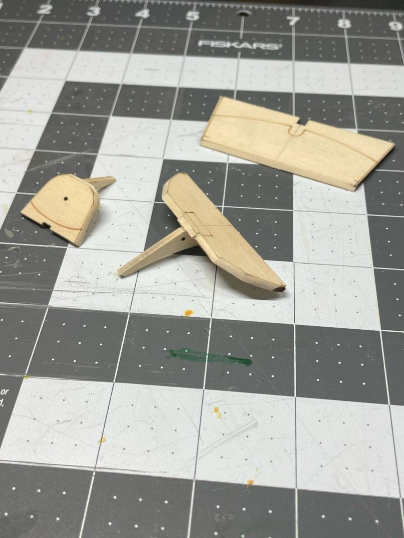
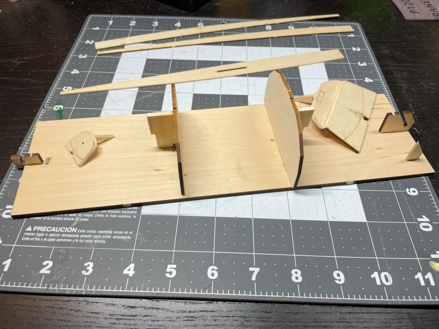


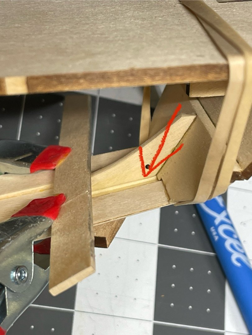

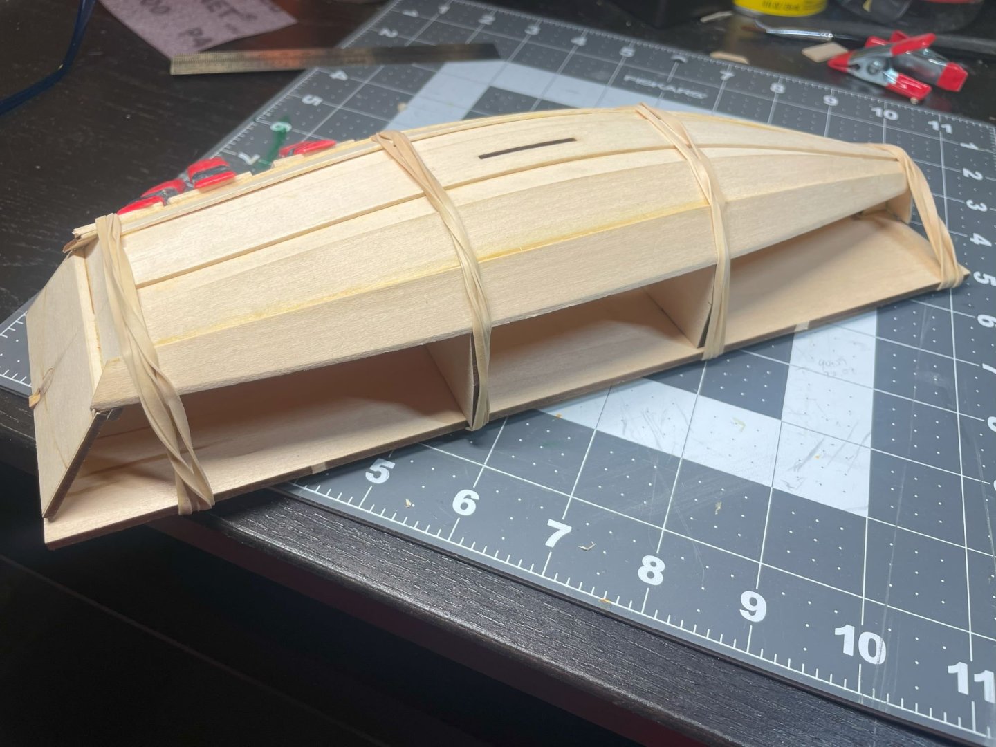

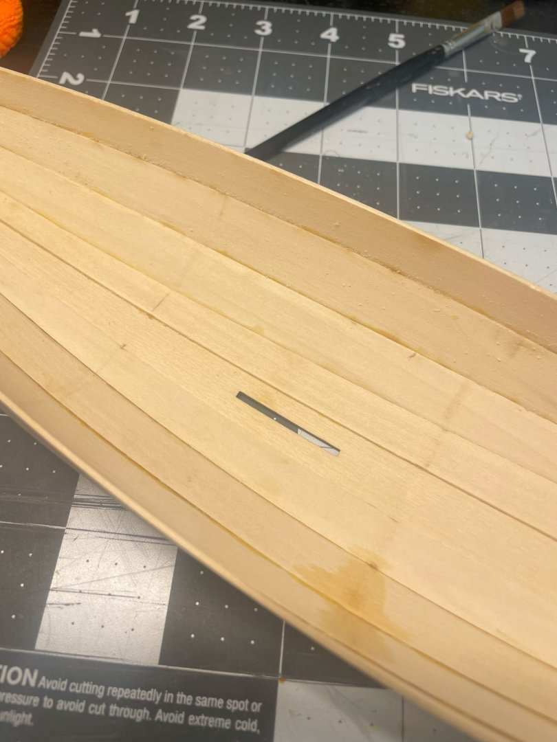
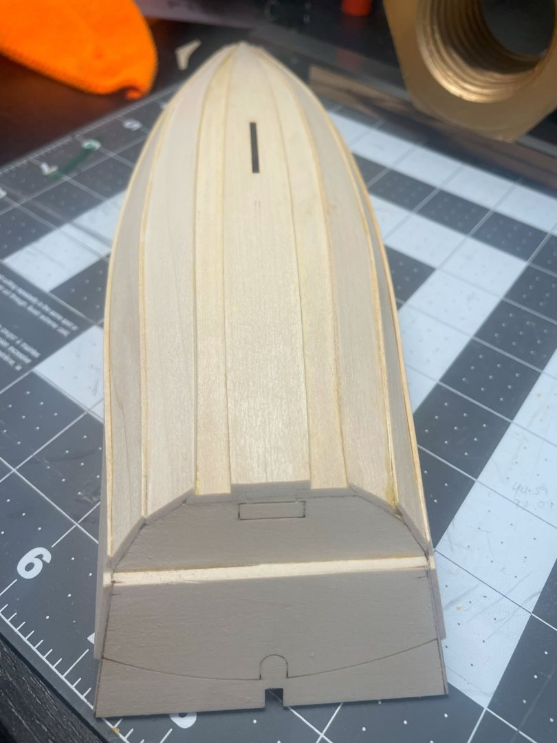
-
 Welcome to my Sultana build log. I plan for my Sultana to deviate from the kit in two significant ways. First, I will be modeling the 2001 Sultana replica, rather than the 1767 original. In addition to pictures taken by myself and others, I'll be using the book Schooner Sultana: Building a Chesapeake Legacy by Drew McMullen with photos by Lucian Niemeyer. The book covers the construction of the 2001 ship with lots of descriptions and photographs. Best of all, there is an appendix with measurements of many of the main components. The second significant deviation is this.
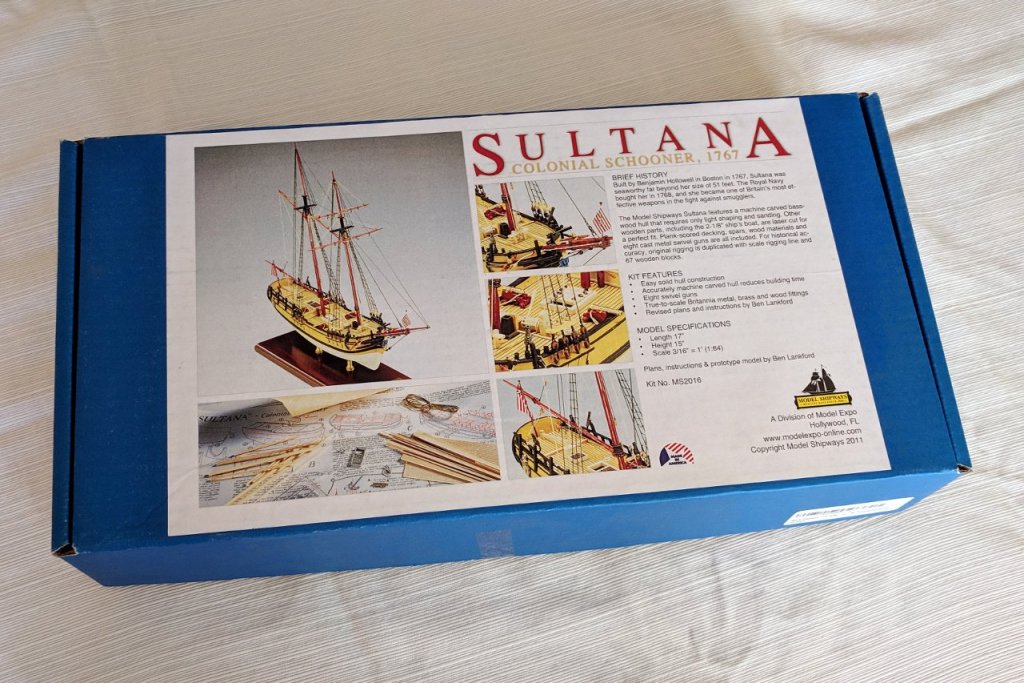

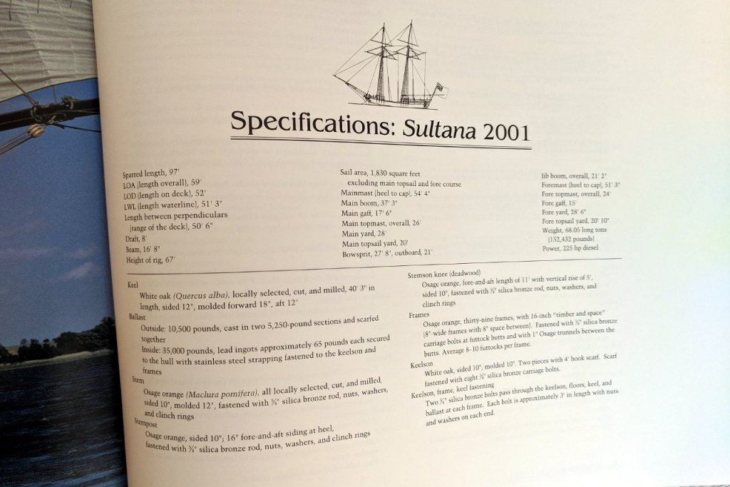
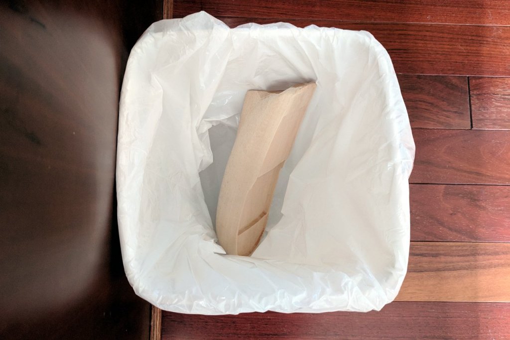
- 222 replies
-
- 5
-
-
- sultana
- model shipways
- (and 1 more)
-
Next kit on deck in the Model Shipways Series. A few notes and lessons learned: Some folks put tables of contents on their opening post that they update. I thought I'd put some notes on key points folks might look out for if they work on this model. I did that post-mortem for the NRG hull. I'll doing this as I go for the Pram. - Definitely check out several build logs as you go along. While there are detailed instructions, sometimes they are a bit confusing. And in one of the first steps, the description of what to do is opposite to what they show in the photos. I decided to follow the photo, which was what a lot of the build logs do here. And one log that chose to follow the written instructions ended up having to hack things later. - I found another place where the photos do not align with the instructions. A photo shows the wrong part attached to the lower stern transom. - The build board is not very sturdy and it’s easy to break the holders on the building board for the bow and stern transoms. Just think of them as a surface for holding rubber bands and/or clips and to help set the spacing between the bottom planks. - It’s easy to misposition pieces that will support other pieces later. For example, I had too much space between the two forward-most bottom frames so when I tried to add the mast step several steps later I had to unglue (with isopropyl alcohol) the forward-most bottom frame and reposition it back a mm or two). - Another example is the positioning of the seat frames. It's not entirely clear from the instructions where these should go. It's more following the photos than anything else, unless I missed some key to unlock. I recommend skipping ahead several steps and getting the seats. You can figure out where the seats need to go and hence where the seat frames need to go better if you do them together than trying to position the frames and them hoping that things fit. You do need to (probably) sand and shape the seats to get them to fit, even if the seat frames are positioned perfectly. But doing the seats and seat frames together will probably result in a better final product, and a bit less frustration. - Model Shipways paint is not the best. It’s a bit thick and gritty. Definitely need to thin with water. I’m using it because it came with the three-kit Shipwright combo. Also, the basswood isn’t the smoothest wood so it doesn’t matter as much as it might if the wood wants “fuzzy”. - A heads up: when you get to using the copper tubing and copper rods, the instructions don’t seem to give the right thicknesses. There are three kinds. Use the one that fits for a particular step. - The instructions say to tape the sail material to a cutting board. They do say that it needs to be a clean one, which mine was. But it was a used one. Maybe it was my particular cutting board, but because it had been used, when I taped the sail down and then brushed on watered-down glue to stiffen it, when I took the sail off the green cutting board there were some green stains on the sail. I tried to airbrush paint the sails but that didn't work. So I'm having Model Expo sent me a new sail. Next time I'm going to try to first put some Saran Wrap down on the cutting board, then tape and water-glue the sail. Hoping the Saran Wrap won't stick. If someone has other suggestions, please let me know. - One challenge is rigging the mast. I'm gathering that on this kind of boat, the mast is just in place when using it since the mast just rests in a circular slot - it's not glued or otherwise secured (if you let go, it will just tip over). A challenge is that since the mast is not secured in place, you need to hold the mast and then try to figure out how long and how tight the rigging lines (one in front, two on the side behind it) need to be and secure the rigging line and knot them off. You're running out of hands unless you have someone helping you. The quad hands (from quandhands.com) are a lifesaver (I actually got a quint hands from them). Buy it directly from them because a lot of the ones sold on amazon seem to be knockoffs (same yellow base without the quad hands logo and seemingly poor quality based on some reviews - people thought they were getting a real one).
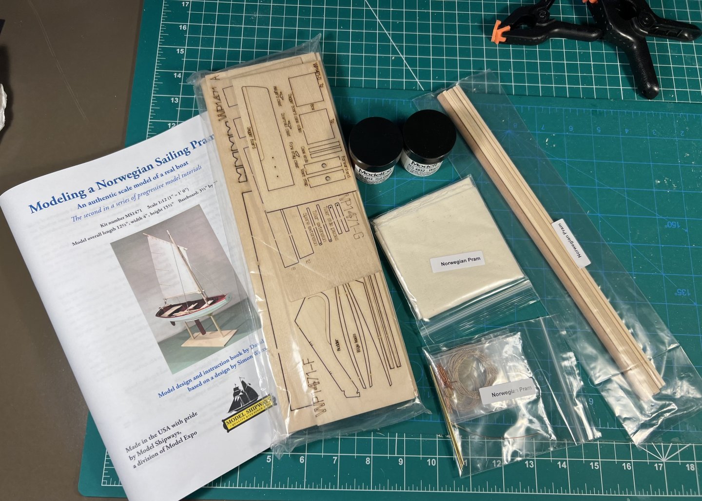
- 63 replies
-
- 6
-
-
- Norwegian Sailing Pram
- Model Shipways
- (and 2 more)
-
 Dear Friends, It's been a while since I've built my first model so I've finally decided to continue with this wonderful hobby. After some doubts on whick kit to choose I went for the Confederacy from Model Shipways. I've ordered it through Cornwall Models in the UK and the've dispatched it the same day - amazing service! Got the kit yesterday and to be honest I was slightly dissapointed with the quality of the castings (ok I knew it from this forum they are not amazing), but also some laser cut parts came off as they were not properly packed. Anyway seems that all the little pieces are intact
 -
 I've started my second build - the Bluenose. I've had this kit for about six months, but didn't even open the box until I finished my Phantom a couple weeks ago. The Phantom was my first build, to get me exposure to basic ship modeling and rigging. I chose solid hull for that one so I wouldn't have to tackle hull planking. I chose the Bluenose for my second build because it still has relatively straight-forward rigging, and the hull planking doesn't require a lot of complex work. It is also a little larger scale, which lets me focus more on detail. I spent about a week 'preparing'. I scanned in all the plans, inventoried and labeled parts, etc. For this build, I've purchased Bob Hunt's practicum, which I'll be following only partly. I got the practicum because sometimes I just want to sit and read how somebody tackled the build - even if I end up going my own way. Knowing this was going to be my next build for some time, I've been following a number of Bluenose builds here on the forum. Build logs from bhermann, darr, jrw1970, dborgens, mrjg, and popjack (among many others) have given me a ton of tips, a lot of inspiration, and a good deal of insecurity (you guys are soooo good at this....). To get started... All the parts were inventoried and labeled. This is my fourth kit from Model Expo (two Model Airways planes, second Model Shipways ship), and this is the first time the wood has come labeled. I had my caliper out ready to start measuring and sorting wood stock. Maybe I was just unlucky the first three times. Keel Assembly The three pieces of the keel were cut out and assembled. This took a few days, because it didn't go smoothly and I knew that messing this up would have repercussions. Two major problems...first, the third piece simply wasn't the right size. It wasn't an issue with the tab - the piece was physically taller (top and bottom) than part #2. So, I drew on the reference lines from the plans (since I guess reference lines are there to refer to) and used those to decide how to line things up. A little sanding, a little shimming, and I've got a keel. It came out straight, so I'm happy. The second problem with the keel was that while sanding off laser char on the top of section 2, I guess I went a little crazy. Ended up with a beveled edge where it meets part #1. I took too much off. Solution? Take more off! I leveled it out, glued on some thing wood stock, and brought everything back into alignment. So, the rabbet... Rabbet It looks days for me to get the nerve to make the first cut. I've read everything I could about cutting the rabbet, but none of it gave me much confidence. With my first POB build, something about carving away at the keel I just spent days aligning didn't make me very comfortable. Most of the stuff I've read is either discussions on what the rabbet is (which was helpful), or it was build logs that mentioned how concerned they were about cutting the rabbet, but that it wasn't much of a big deal. So I guess on the other side of this, I'll be fine... I tried the 'cut out a copy of the plans and trace the lines' method, but I wasn't happy with the result. I had little confidence that it was 100% accurate. So, I measured the distance from the deck to bearding line at each bulkhead, and transferred that to the keel. Then I measured the distance from that to the rabbet and marked that on the keel. I ended up with a series of 'dots' at each bulkhead. Then I used the cut out plans, aligned to these dots, to trace the lines. Doubled checked against the plans, and I'm good to go. Awesome! I've managed to stall cutting the rabbet for a few more days! Finally, I got up the nerve to cut. Here's how I did it (which may be totally wrong, but it worked...) Score both the rabbet line and bearding line with a #11 blade. I started between bulkheads I and J, and I did one bulkhead-space at a time. Take my chisel x-acto blade, and push it into the score on the rabbet line, matching the angle for the bottom of the plank. I cut a small (1" long) piece of plank to help with the process. This gives me a lower 'lip' on the rabbet at the right angle for the plank. Repeat this for the length of the section. Take my chisel and carve down from the bearding line to the rabbet line, where I hit the deeper cut I previously made. Big chunk of wood comes out. After I've 'roughed out' the section, drop the test plank in and slide it along the cut. It should sit at the appropriate angle against the hull, and anywhere that it doesn't seam up with the rabbet line just right gets some touch-up work. Repeat for every section, on both sides. Sand when done. Everyone was right - it isn't hard, and doesn't take that long (maybe 2 hours total spread over 2 days). Maybe there isn't much discussion on how to actually make the cut because after you've done it once, it's no big deal. I added reinforcement blocks over the joints in the keel (just seems like a good idea, and all the cool kids are doing it). Then I started dry-fitting the bulkheads. I've lightly sanded each of the bulkheads - removing just enough laser char to keep me from smudging everything any time I touch the parts. The rest of the laser char should get cleaned up when I fair the hull. Like many others, my bulkheads came as plywood. They seem stronger, but they are a little harder to work with (cut/sand). Each one has been lightly adjusted, along with the slots in the keel so they don't fit too snug. Next steps will be to install the sternpost and trim the tops of the bulkheads. I know some people chop off the tops of the bulkheads and use fake stanchions, others follow the MS instructions and trim them back so the bulkhead tops become some of the stanchions. I'm not 100% sure which way I'll go, but I figure if I trim them before they go on, I won't risk breaking anything, and if I cut them off later all I've lost is time. After all that is done, I might be ready to start gluing in bulkheads...
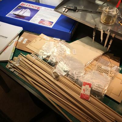
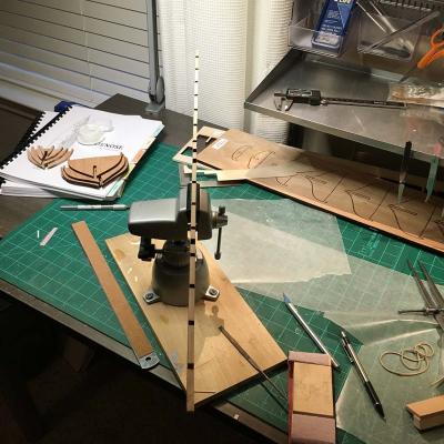
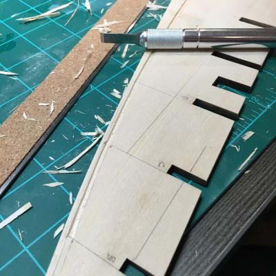
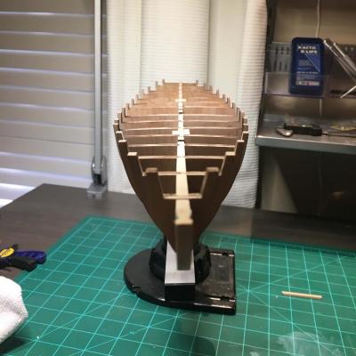
- 245 replies
-
- 10
-
-
- bluenose
- model shipways
- (and 1 more)
-
 Hello everyone, it's time for yet another build log of the Model Shipways Grand Banks Dory! This is my first ever model boat/ship, and I'm coming at this with precisely zero woodworking experience, so hopefully I am the target audience for this kit. My long-term goal is to work my way up to Vanguard Models' Speedy, so to that end I got the Model Shipways 3 kit learning set to get me on the road to a more complex ship. To any experience builders who may read this build log - I welcome any feedback at all! If you spot that I'm doing something stupid that I seem oblivious of don't feel bad about letting me know - I'm here to learn a skill that's totally new to me and any feedback (including critical feedback) would be very helpful . To start with, I took an inventory of all of the listed parts. Since this was the 3 kit set, this also came with tools and paints. All of the listed wood parts were there including an extra strip of 1/8" basswood. The tool set was missing the sandpaper and the chisel blades, but it did come with some pliers, clippers, a pair of (not very good) files, and a pin vice drill and bits, none of which were listed which was nice. It was a bit shocking feeling just how thin the plank sheets are. It's one thing to read a number like 1/32" and another entirely to feel it in your hands. I'm afraid it'll snap if I look at it wrong! Gluing the bottom together was pretty straightforward. Oddly the two side pieces didn't have a full set of laser markings and the ones that are there look like they were done by hand, but this didn't interfere with the assembly. The bottom cleats were also straightforward. Since the kit didn't come with sandpaper I had to make due with what I had lying around. The instructions suggest to use 150 and 220 grit sandpaper. I only had 120 (which seemed too course) and 220, so I stuck with 220 for everything. At first I was worried this would only be good for finishing and not for removing material, but after using it to shorten the cleats to the proper length and bevel them I wonder what you would even want the 150 for. This wood is so soft that the 220 made quick work of shortening the cleats and I found it was easy to accidentally over-bevel with even just a couple of back-and-forths. For the two cleats on the ends where the angle of the bottom's side is most extreme I figured I would try to match that angle as a way to practice beveling to an intentional angle. Attaching the stem and transom assembly was a bit trickier. It was hard to figure out a good way to make sure they were truly even with the center line of the boat. I did my best using the straight lines on my cutting mat as a guide and to my eye they look correct, but I do slightly worry that since I didn't use any kind of jig to ensure straightness, any imperceptible deviations may be magnified later in the build. With the transom assembly, though, I worry I may have already made a mistake. I lined up the stern knee with the marks on the boat's bottom just as I did with the transom, but doing so resulted in a bit of an overhang where the knee/transom stick out a bit past the point of the bottom. Looking ahead in the instructions I see that a photo shows their stern knee glued very close to the rearmost bottom cleat leaving no overhang, so I am considering breaking out the isopropyl and redoing this step. But on the other hand, a quick survey of build logs shows at least a couple that appear to have done the same thing I did with no apparent problem. Any thoughts on if it's worth trying to remove this glue and redo this? At the moment the bottom is sitting in the bender. Later today I'll start working on the frames while I decide whether or not I want to redo the transom.
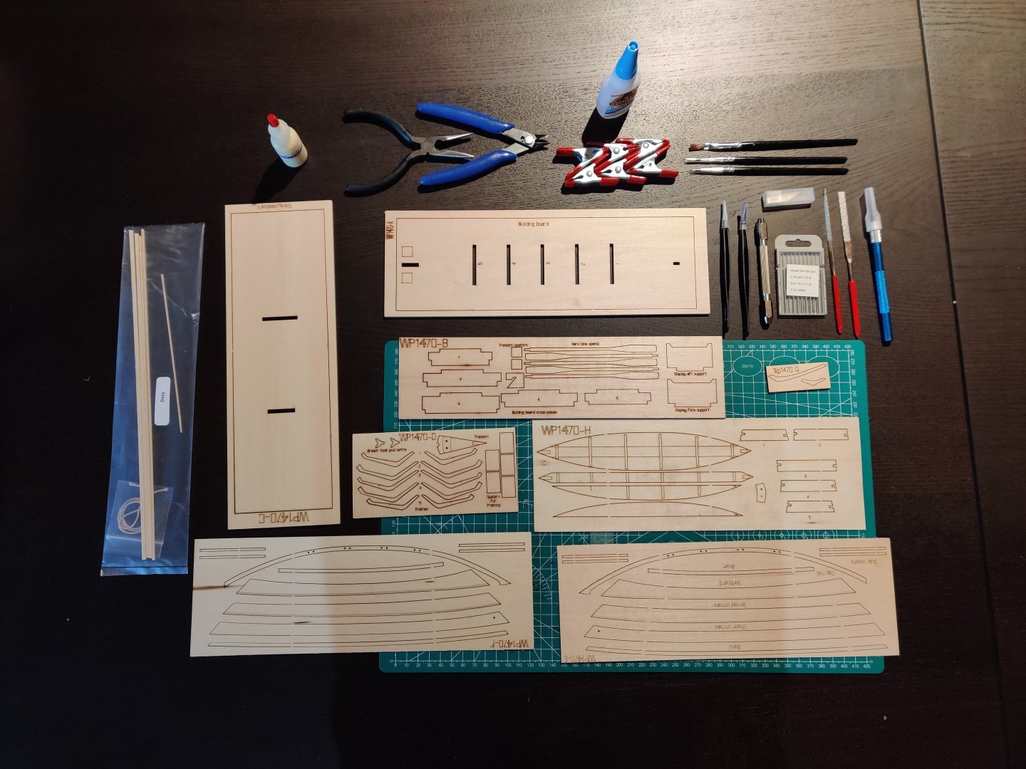
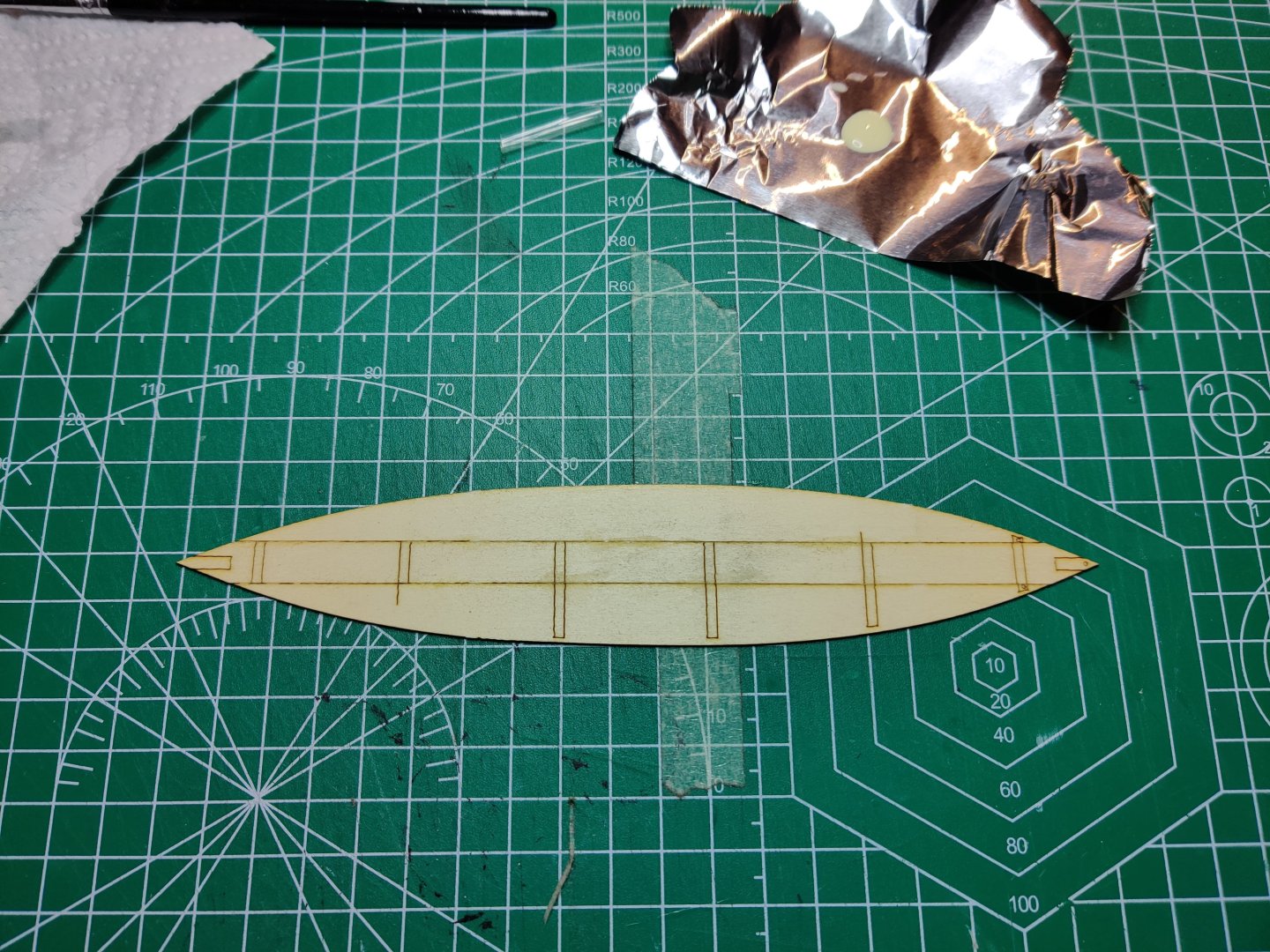
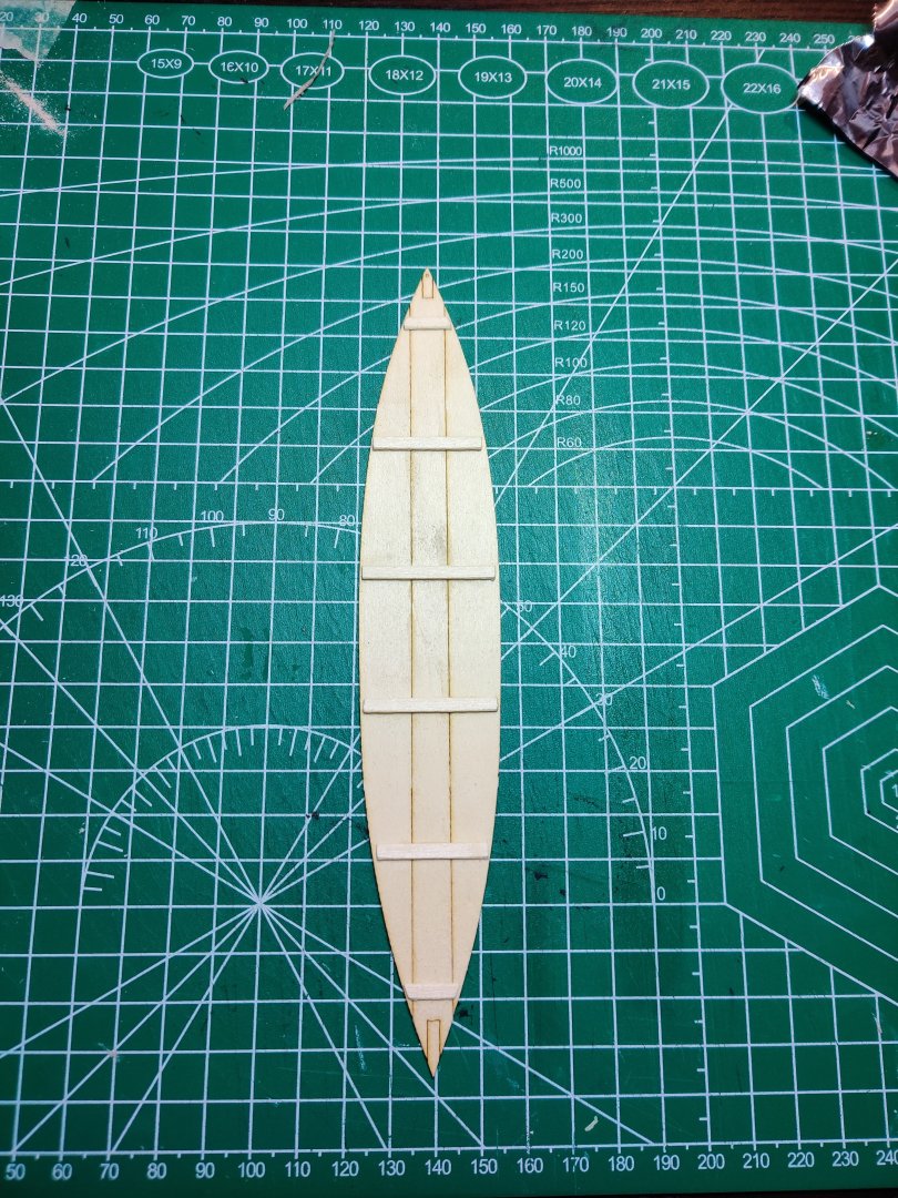

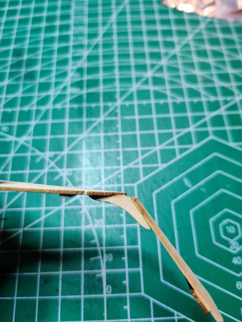
- 28 replies
-
- 6
-
-

-
- Lowell Grand Banks Dory
- Model Shipways
- (and 1 more)
-
 Started on building the brig syren, and the first photo so fare am planing to get some lights on, so its know time to plan this before I start going to fast forward


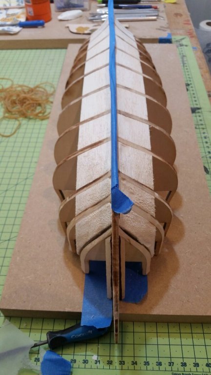
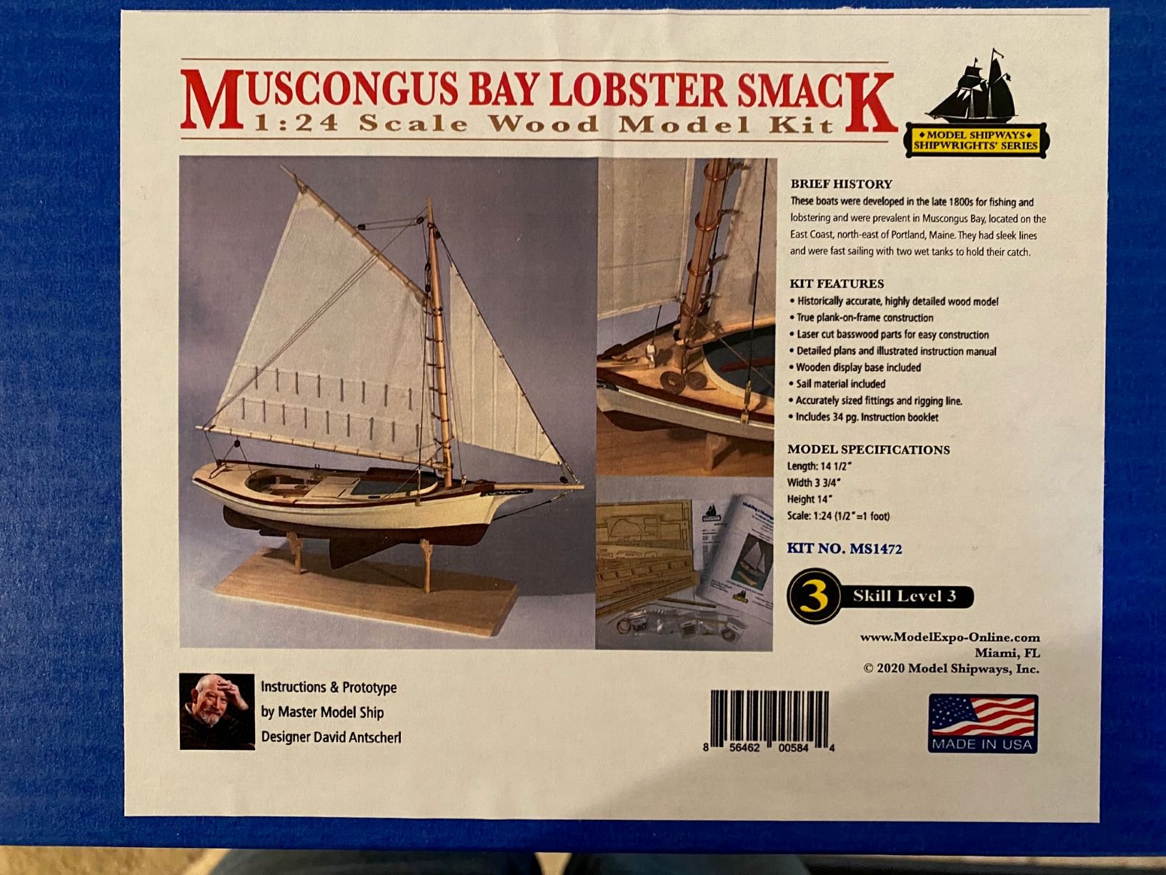


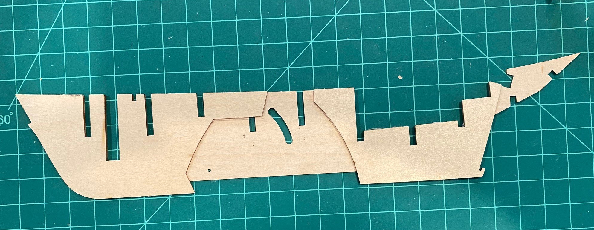
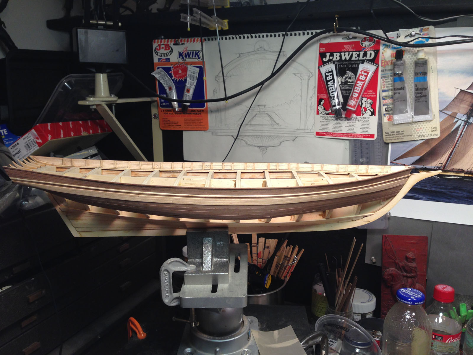
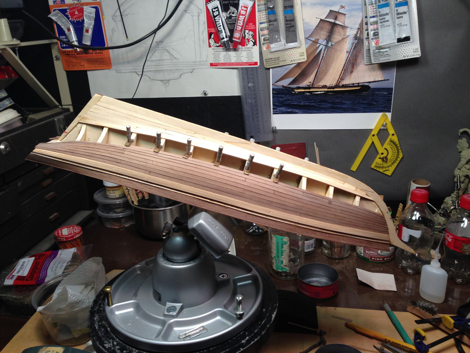
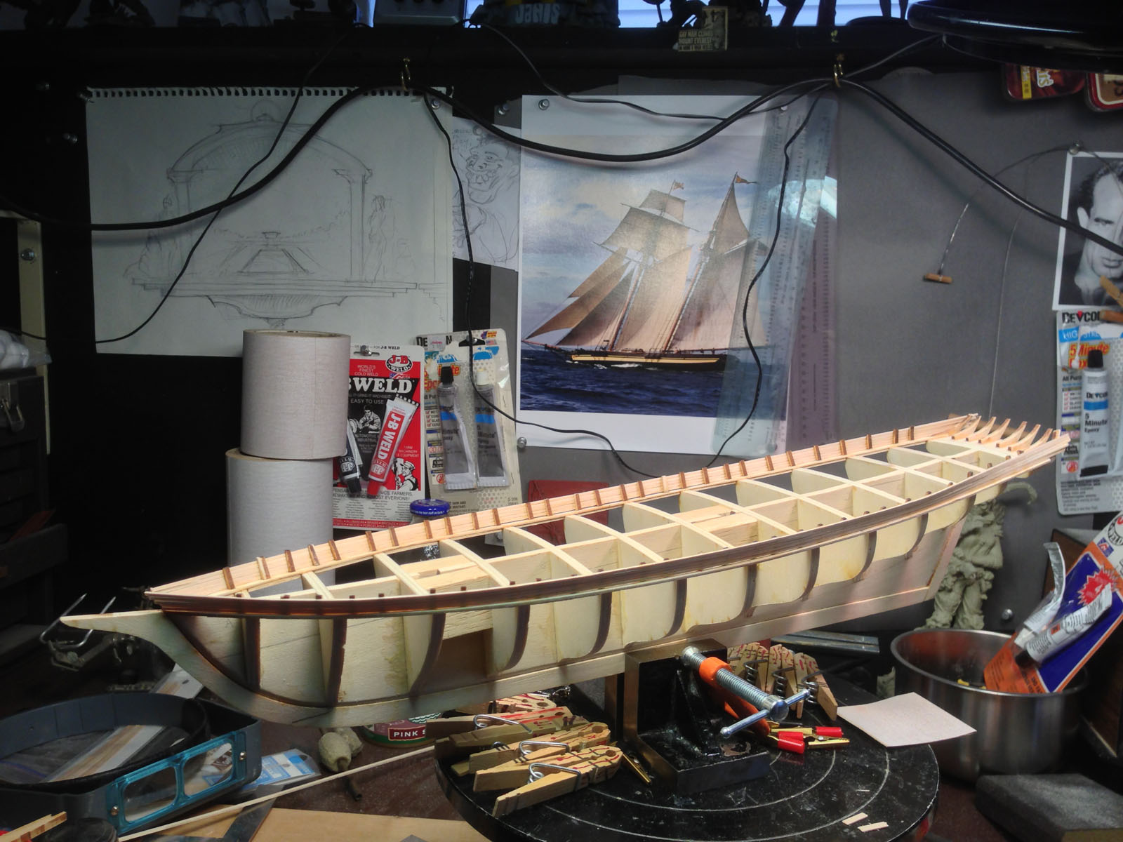
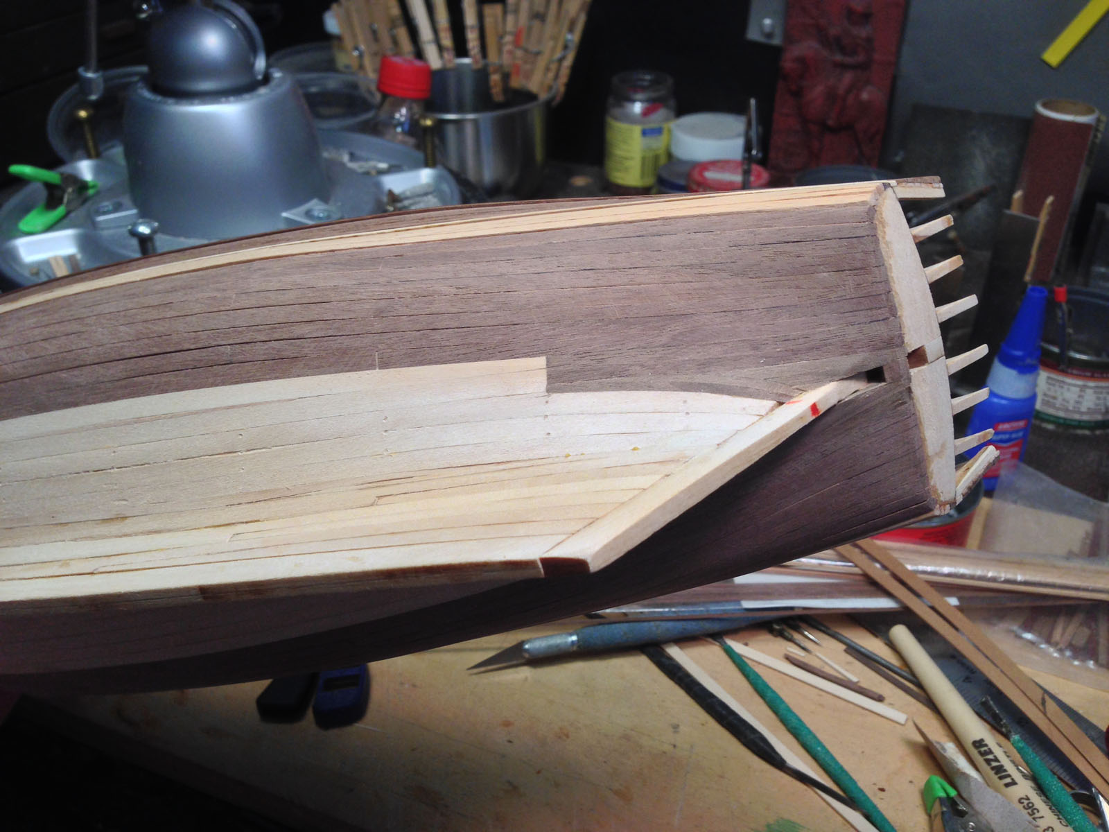
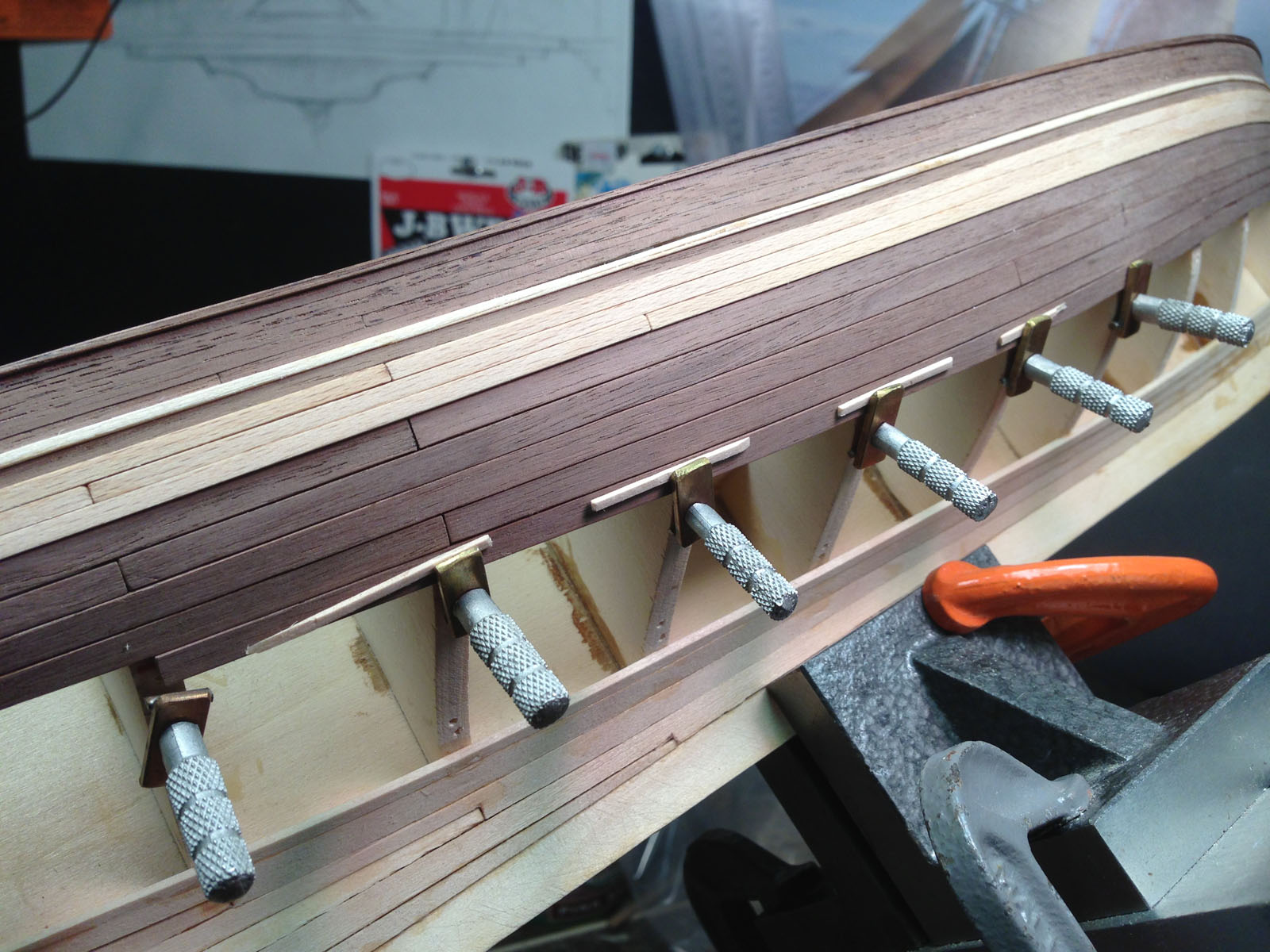


.JPG.cf70ff860dda6e3742c61b76ab5d8ecb.JPG)