Search the Community
Showing results for tags 'Half Hull'.
Found 23 results
-
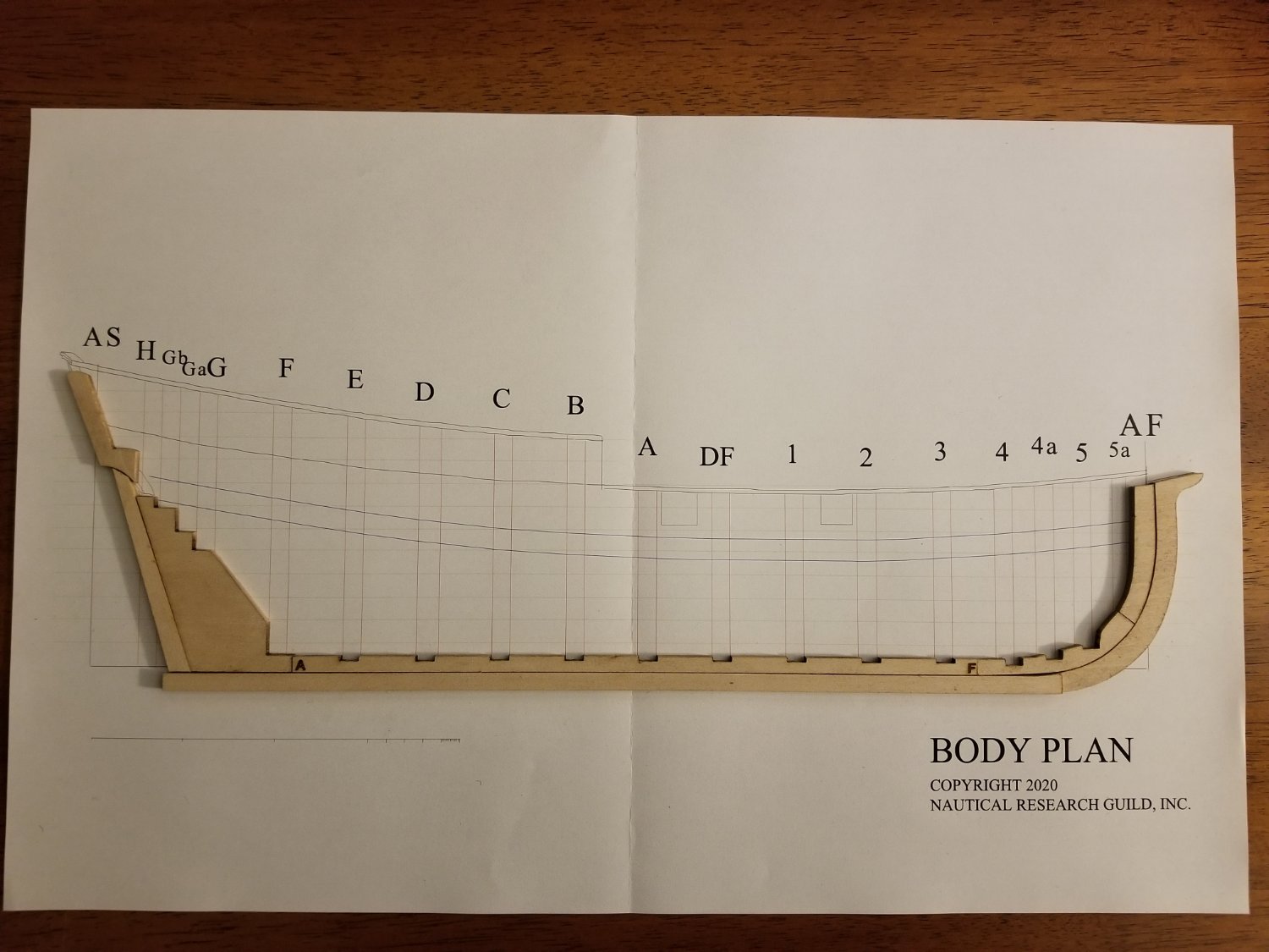
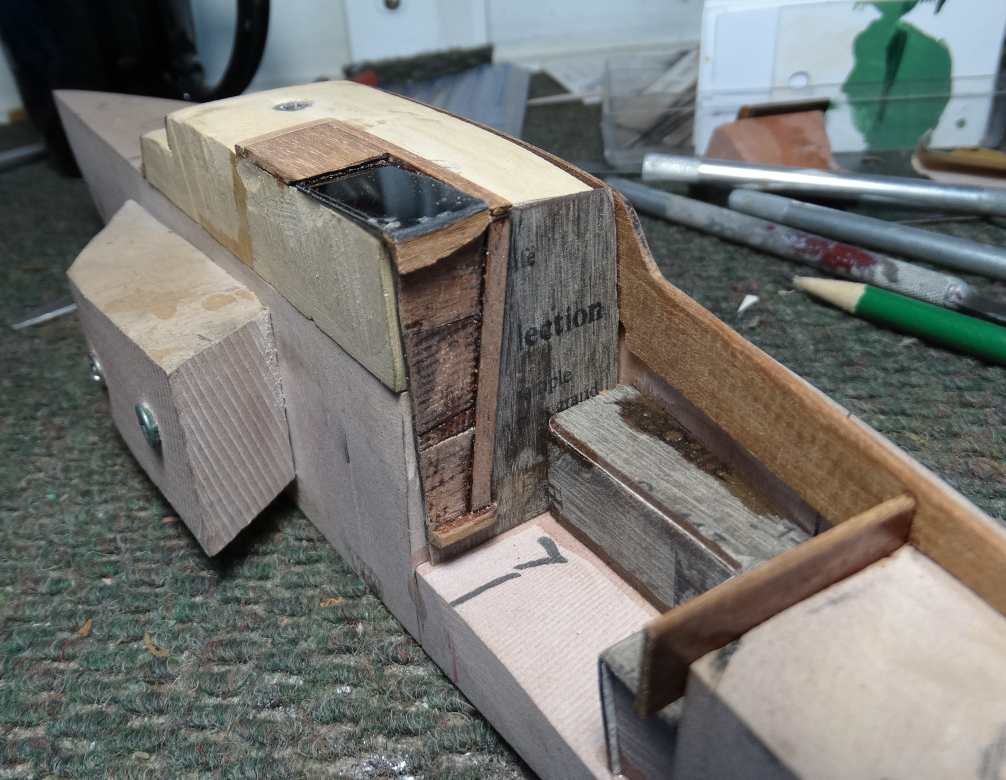
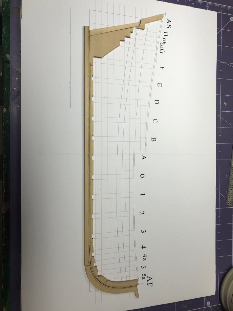
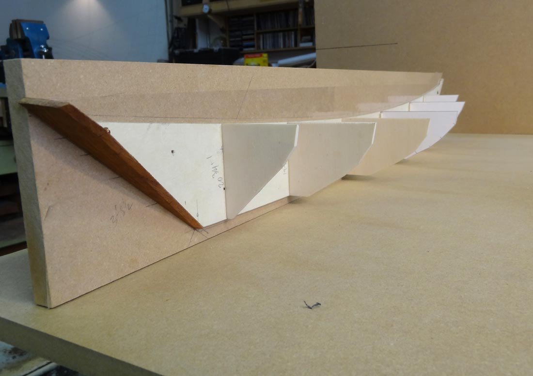
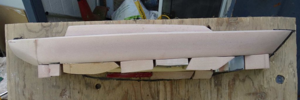
 While working on my latest model, HM Cutter Trial from Vanguard Models, I realised that it would be a good idea to have some further practice in hull preparation and planking before embarking on another full ship project. I’m hoping that this project will teach me some new techniques and help me make a better job of planking than I have previously. I am using the suggested ¼” foam-board as a base on which to build and used spraymount to glue the body plan to it. Laying out the keel, keelson stem and stern, it is clear that some trimming and fitting of the bow keelson is needed The whole kit is made in basswood making it pretty easy to cut and sand. The risk is taking off too much so slow and easy is the rule. Once the stemson is cut to length and sanded to fit the keelson lines up pretty well with the drawing. I didn’t need to fettle any of the slots for the bulkhead on the main keelson but the bow keelson required a bit of a tickle with a sanding stick. The rabbet is marked up with a pair of compasses. I measured the thickness of the sheets provided for planking which varied between 0.85 and 0.99mm. I took 0.9 as a rough mean and marked the rabbet. I used a chisel to remove the rough, then a file and finally scraped it clean with a razor blade. The keel and keelson were straightforward as a simplified 45º angle was used for the whole length. The stem is a little more difficult to do with a changing angle as the rabbet rises up the the stem pieces. However the manual provided and Toni’s log Half Hull Planking Project - Planking Downloads and Tutorials and Videos - Model Ship World™ provide plenty of useful detail and photos to help work it out Once the rabbet is cut, the keel and stem pieces can be glued up. I have used minimal glue to fix the pieces to the board to make it easier to remove the model when completed. At this stage the deadwood and stern pieces are not glued . David
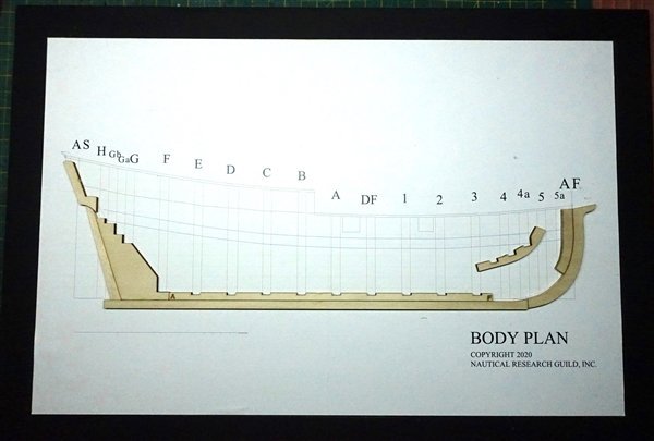
- 16 replies
-
- 7
-

-
- half hull
- Half Hull Planking Project
- (and 2 more)
-
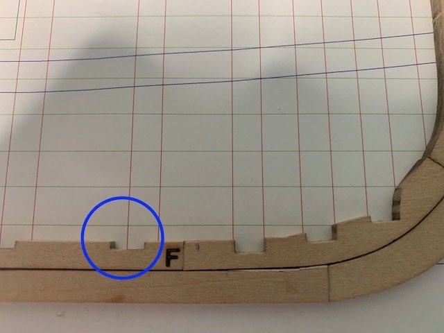
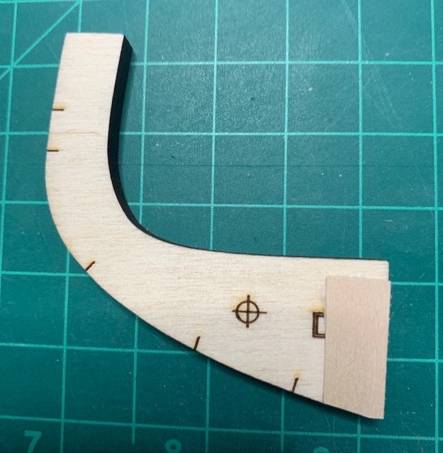
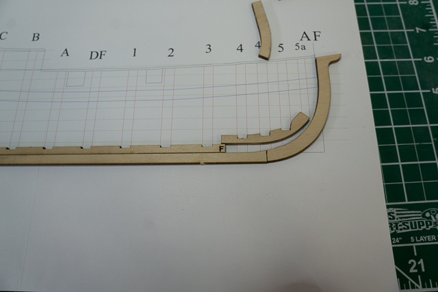
 Although I'm still working on my scratch-builds, I got started on this recently. I received the NRG Half-Hull Planking Kit as a Christmas gift. I'm looking forward to building it and learning a lot about planking a curved hull in the process. I'm also glad that the result should be relatively easy to store, display, and transport, as I don't have a ton of room. Given work, I will probably be building this pretty slowly. As can be seen, the kit is pretty straightforward in terms of components. Overall it looks like a nice kit, and the instructions are quite thorough, which I appreciate. I'm still waiting on getting a foam building board, so nothing is glued yet, but I've sanded off the laser char and removed the basswood parts of the model's backbone (keel, stem, etc). In general, the parts fit together well with minimal sanding, although I'll have to do a little more shaping where the keel rises slightly near the stem. The keelson slots fit the frames well. However, there is a slight issue with the fore keelson, and I thought I'd ask for advice before proceeding. The slots in the fore keelson don't line up with the markings for the frames on the plans. I see two main ways I could deal with this. One would be to trim the end of the fore keelson so it aligns better with the frame markings--more or less like below, although there the fore keelson is propped up above the other parts. That said, if I do this I'll be throwing off the fit of the stemson and of the fore keelson against the stem and keel, which will require a good bit of shaping to correct. The other option would be to simply leave the fore keelson as it is, and cut new frame slots into it. The frame slots will need to be extended anyway. And while this might leave some frames with less sturdy of a connection, I don't know if that would be a serious problem given that everything will be attached to the building board. Comments and suggestions are welcome! I'm looking forward to learning a lot with this kit.

- 23 replies
-
- 7
-
-
- half hull planking project
- half hull
- (and 1 more)
-
 I've decided to pause my other projects since as a result of my stroke my memory has failed in some areas. Mostly it's working but some things are gone forever like "how to plank" while other things are coming back to me. So, after much thought, I've ordered the NRG Planking Project. I've downloaded the manual and am reading through it. The kit should be here this coming weekend.
- 4 replies
-
- 14
-
-
- half hull
- half hull planking project
- (and 1 more)
-
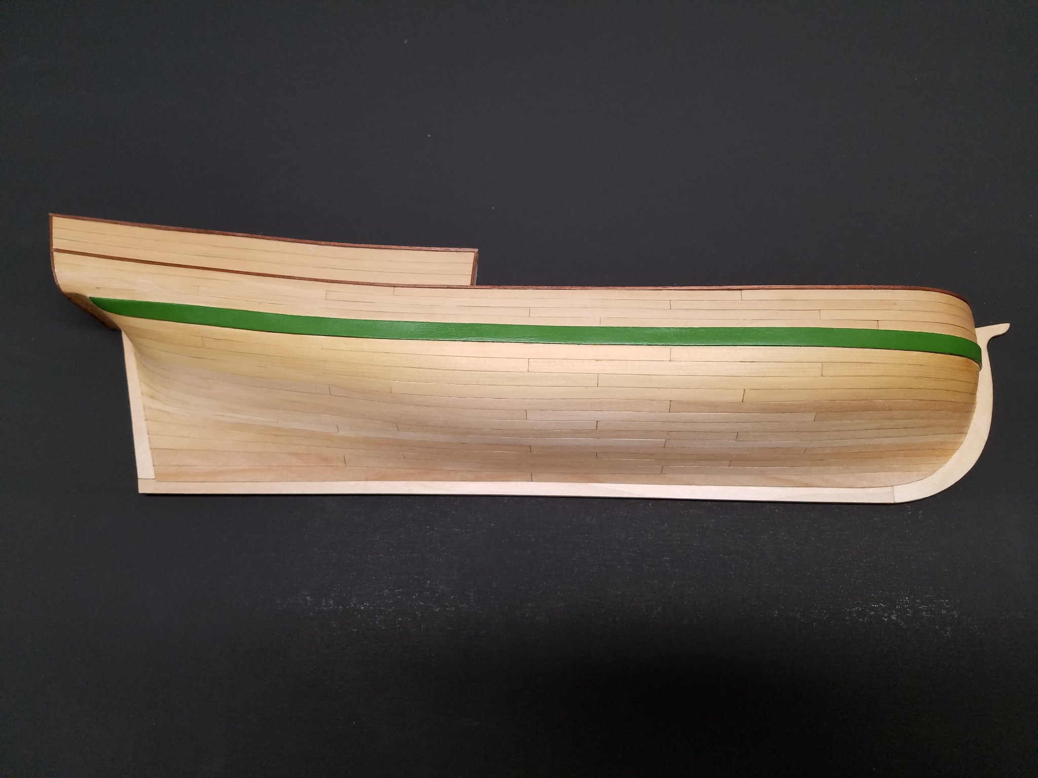
 In dire need of planking & spiling practice before tackling the next project, I was so pleased to come across NRG 18th-Century Merchantman Half-Hull Planking Kit . Actually, this project was started just after last Christmas as a present (to myself) and is now just about finished except for the mounting. I knew I would be dragging this one out because I would be experimenting with different wood, adhesives, wood bending, finishing, etc. and wanted all that to be done on one model rather than one model at a time. That being said, there would be large gaps in posting the log of a relatively small kit. Mike
-
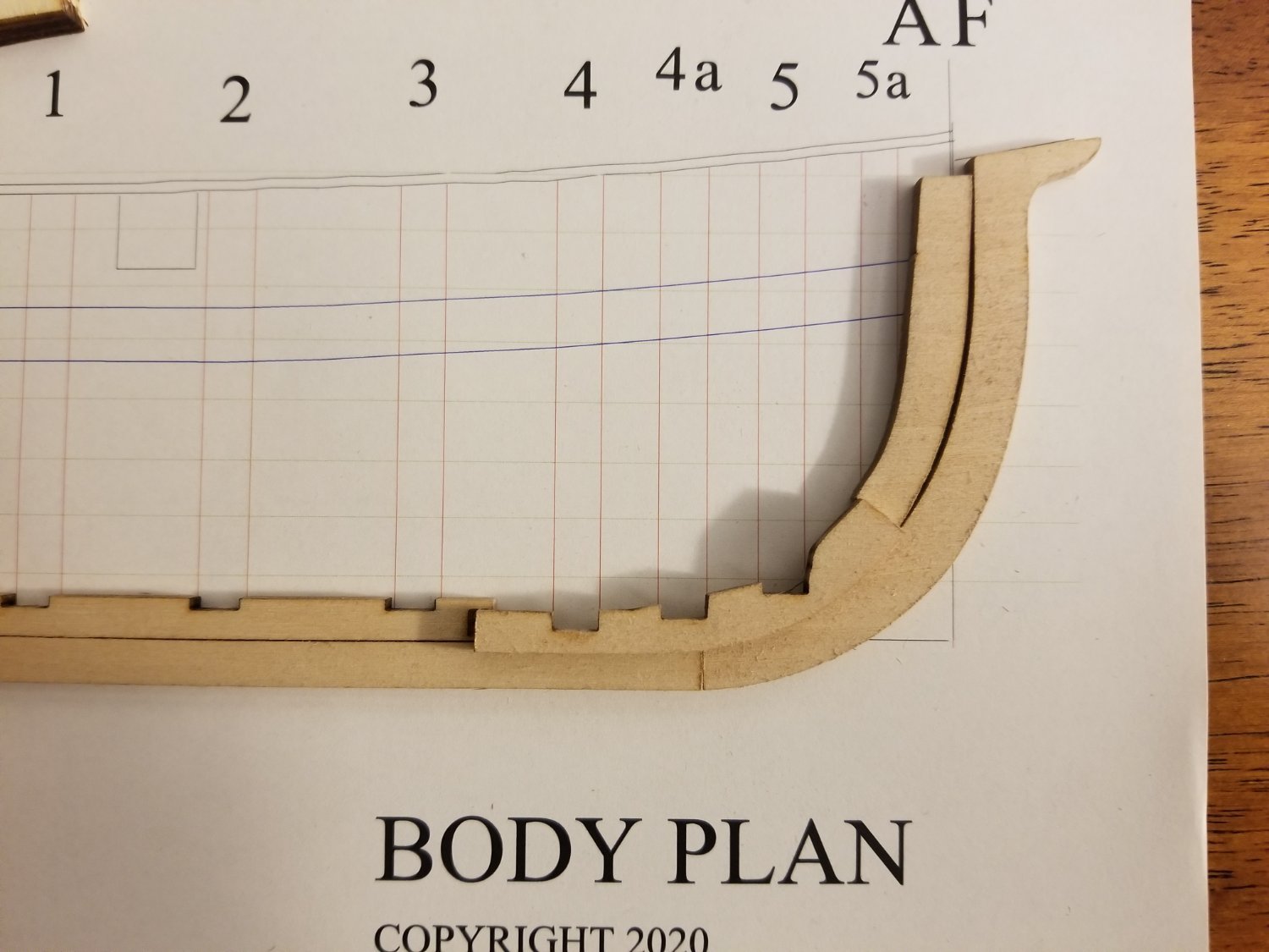
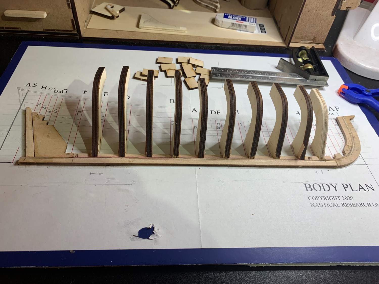
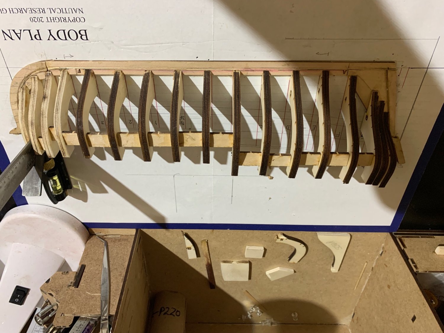
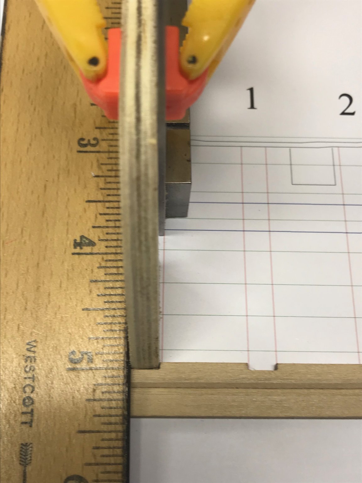
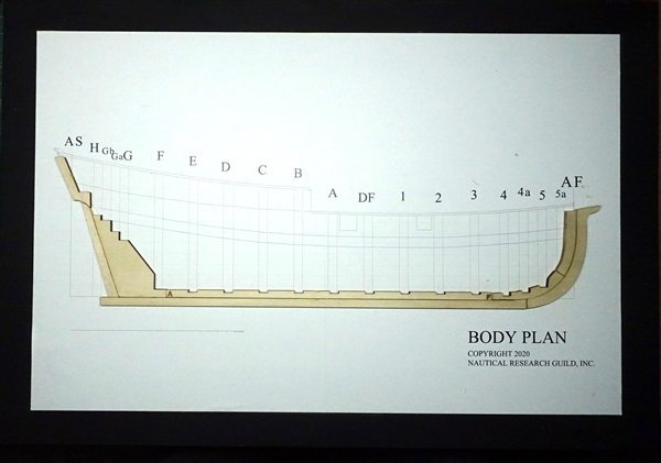
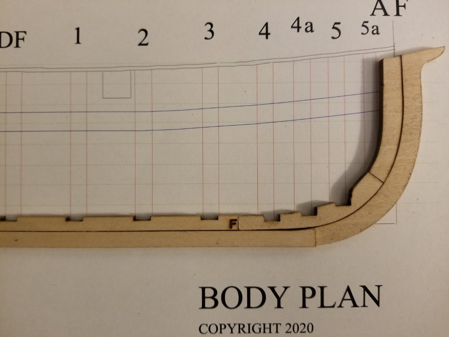
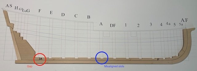
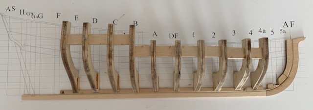
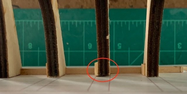
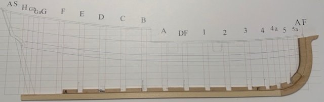
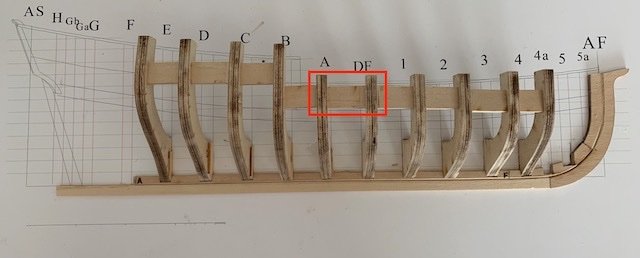
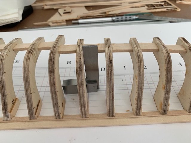
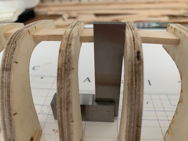
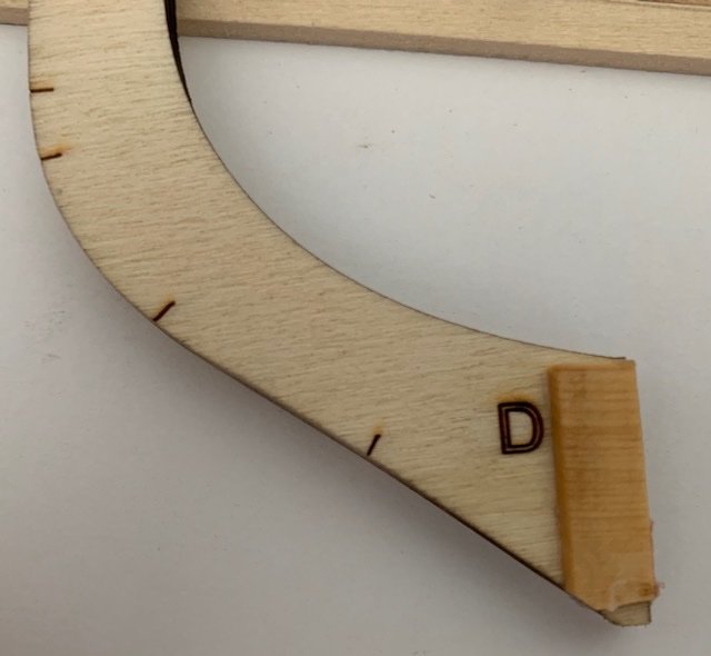
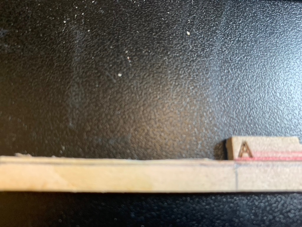
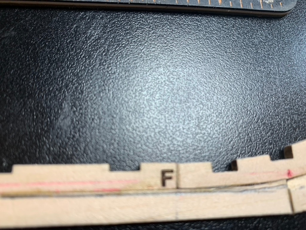
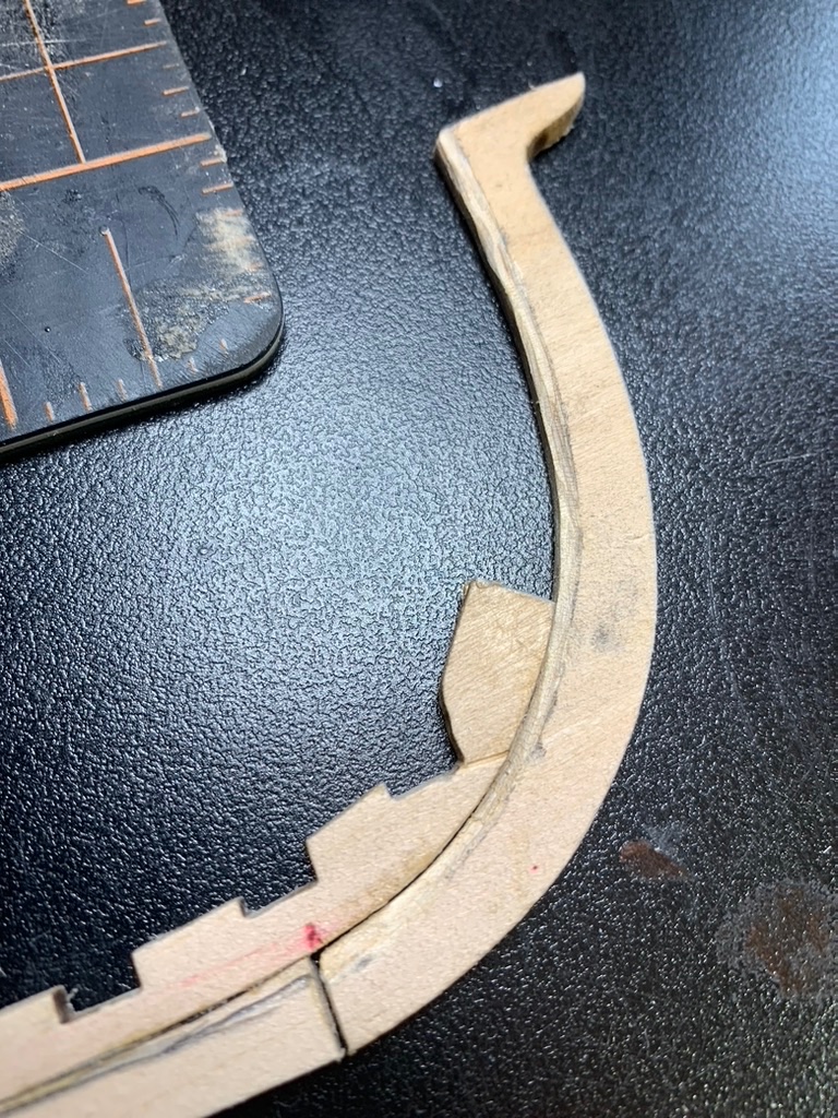
 While working on the planking for the Albatros by OcCre, I realized I needed more instruction on planking. So I joined the NRG and ordered the planking kit. Now, several months later and after finishing the Albatros, I’ve begun. Bookmarks My first step was to bookmark all the Half Hull Logs. After looking at the logs, I eliminated the ones I didn’t think were useful. (No disrespect intended.) Print and bind The next step was to print and bind Toni’s instructions. After printing the manual on my laser printer, I took the printed sheets to Office Depot. It was only a few bucks and I was surprised how fast the binding took; Literally, it took two minutes. Now I was ready to start. Unfortunately glueing the plan to the poster board turned out to be much more of an effort than it should have. First, the spray adhesive was partially clotted. I carefully cleaned out the nozzle but that didn’t help. The spray can had been lying on it’s side in a drawer for years and the adhesive came out in clumps no matter what I tried. So off to the store to get new adhesive. Next when I was attaching the plan to the board, the plan slipped off my fingers and resulted in bubbles. I emailed Mary at NRG about getting a PDF to print. Amazingly, she replied within an hour with a PDF file. As the plans are larger than my printer’s capabilities, I debated whether to print two sheets or go to the copy store. I decided that it would be less error prone to glue down a single sheet than sheets. Subsequently, I went online and uploaded the PDF to the local Office Depot. A couple of hours later, a printed copy. My second attempt to attached the plan to the poster board went perfectly. Starting putting things together When I aligned the fore keelson slots, the slots did not match up as shown in the picture below. I removed some material from the fore keelson to align the first slot. After removing the material to align the first slot, a gap was created between the keelson and the dead wood. I then added a filler piece. As you can see, a number of slots were not aligned with the plans. Whether the misalignment was a problem in the laser cuts or the printed plan made from the digital file was slightly stretched, I don’t know. Regrettably, I threw the original printed plan away. No matter the cause I decided to fix it by cutting the aft end of each slot to align with plans. Then when installing the bulkheads, I could add a filler piece. The rabbet I wanted to create the rabbet using a chisel to develop my skills. I practiced carving the rabbet on a piece of scrap wood. Thinking I had it down I proceeded to the keel itself. It didn’t go so well. Fortunately, the local art store carries basswood and for $1.08 I had two pieces of the same size, albeit without the hump. After adding the hump, I opted for sanding the rabbet. Even if I had a higher level of dexterity, I think that sanding would have been the better choice to begin with given the tiny size of the rabbet on the keel and keelson. For the stem and stemson, I used a combination of a chisel and sanding stick. Deepening the slots in the keelson I found it difficult to not damage the poster board. My only concern about this was how it might impact the frame alignment. This didn’t turn out to be a problem. Placing the bulkheads As mentioned earlier, to align with the plans nearly every slot was too wide. To compensate, I glued filler pieces to most of the frames. Frame alignment error 1 After installing each frame and starting to install the spacers, I noticed one frame wasn’t lining up with the others. On closer inspection, I had installed it at an angle. Frame alignment error 2 I was glad I was using PVA glue so I could remove the frame. I may have been a little too impatient because after removing the frame, a small and critical piece of the filler broke off. But perhaps it wasn’t my impatience, as the filler piece was flimsy wood. I replaced it with a stronger wood. Hopefully, I’ll remember to used better wood for filler pieces in the future. Most of the spacers required removing some of the material. However, between frames A and DF, and frames DF and 1, I had to add shims. With the machinist square the frames look vertical. However, when visually sighting these frames, it looks like frame A is not vertical. I think I’m going to remove frame A and redo it.
- 17 replies
-
- 11
-
-
 Hey guys, So.. due to a case of COVID I finally made a start on my half hull; it's the first time I've ever done anything like this so I feel like it's going to be a little bit rough and a steep learning curve... But we have to start somewhere right?? I came across MSW a year ago while I was looking up some techniques for making a ship in a bottle which I was whittling at the time, & then I discovered this half hull project. I decided to give it a go because it appealed to me that it's the same basic techniques you would use for spiling on a full size vessel & I'd like to learn it. Any help & tips are always welcome! I'll back date the next couple of posts to get my log up to date. Happy Monday everyone.
 -
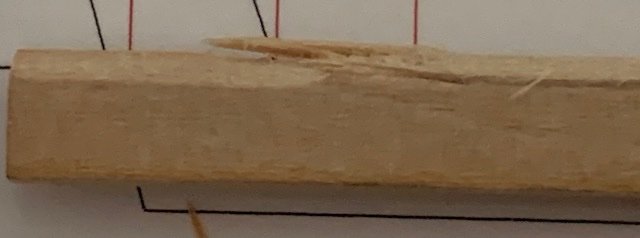
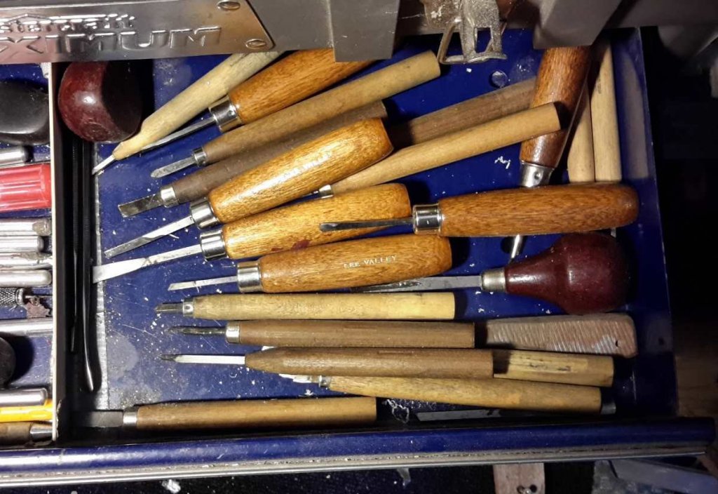
 While scouting the different build logs I came across a NRG Half Hull Planking Project by T Livine and decided that I should get this and learn the proper technique. After receiving this tutorial kit I did my usual kit inventory and all was well. The bulkheads are thicker than what is normally found in the kit and that in itself makes the fairing (shaping) of the hull easier AND it gives more surface for the planks to adhere to the bulkheads. So without further ado, I begin. Pictures will be aded at the end of this segment. Following the instructions I attached the the plan to the building board (1/4 inch foam board) purchase from our local craft store. Then I carefully removed the parts for the beginning of the build. The stem post, keel, keelson, stern post etc. and dry fit them all on the plan. The slots in the keelson for the frames were cut a little narrow which allowed for a better fit after some slight sanding. Then came the first of my worries...the rabbet. Kits usually don't have nor do they mention a thing about cutting the rabbet. I thought of trying it on my Mayflower build but not knowing enough I refrained from trying its until I learned the correct way. This kit was great at teaching the proper way to cut the rabbet. I wish I had known about this kits for my other builds. After reading and re-reading the method in the tutorial, I carefully marked the rabbet and used a small file to carve it out. I think I did a fairly good job of it. I then removed the frames from the supplied sheets and sanded off the char so the frames could be glued. Did you know that glue doesn't hold well on the areas with char from the laser cuts? I didn't! Starting with the first three frames, I had to file just a little off of one of the slots in the keelson for the frame. It took me three days to get all the frames mounted to the keelson and now I have to add the supplied spacers between frames for stability and strength. Next thing will be to mark the bearding line and remove the deadwood below and aft of it. Well stay tuned. I'll add the missing photos when I figure out why they won't post here. Until next post....build on! Dry fitting the keel, keelson and stem post. Marking the Rabbet on the Keel and Keelson After twisting my knee working outside, I finally got back to the planking tutorial. I tackled the bearding Lind, deadwood nd most of the remaining frames. I still have a few remaining frames and the transom to take care of before I start fairing the frames. This time I won't have the false deck to help me get the shape correct but this IS a tutorial right! These next photos are where I am in the build now. Somehow the last photo wants to upload upside down.
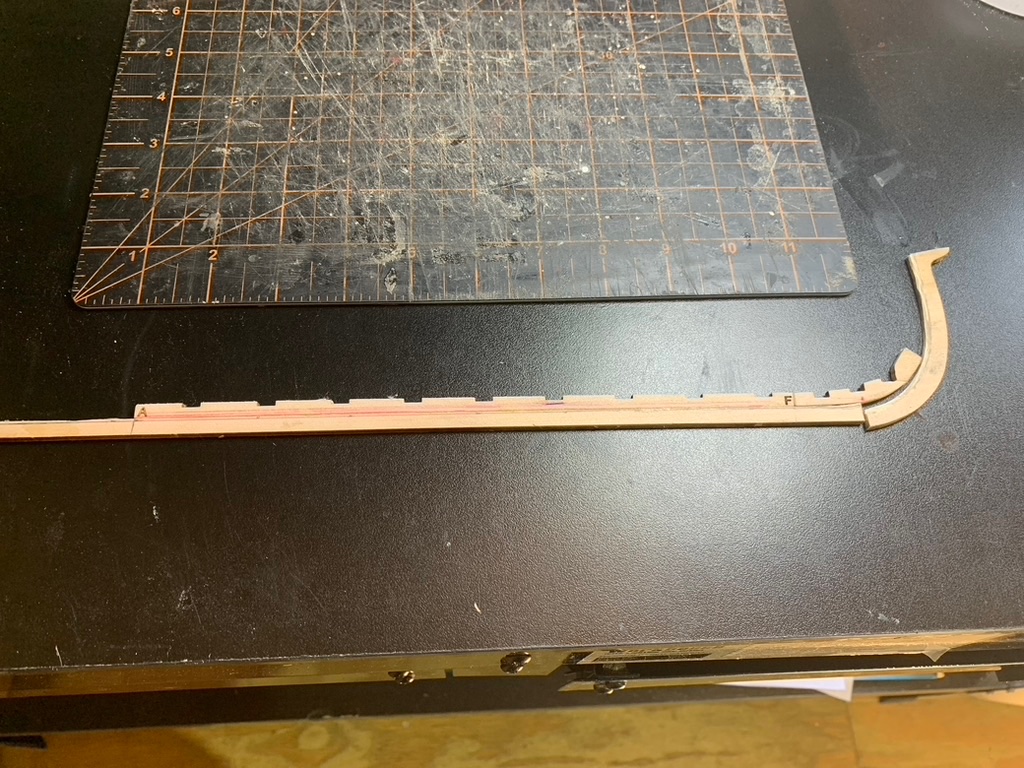


- 4 replies
-
- 7
-
-
- half hull planking project
- NRG
- (and 1 more)
-
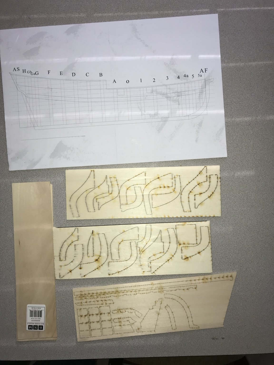
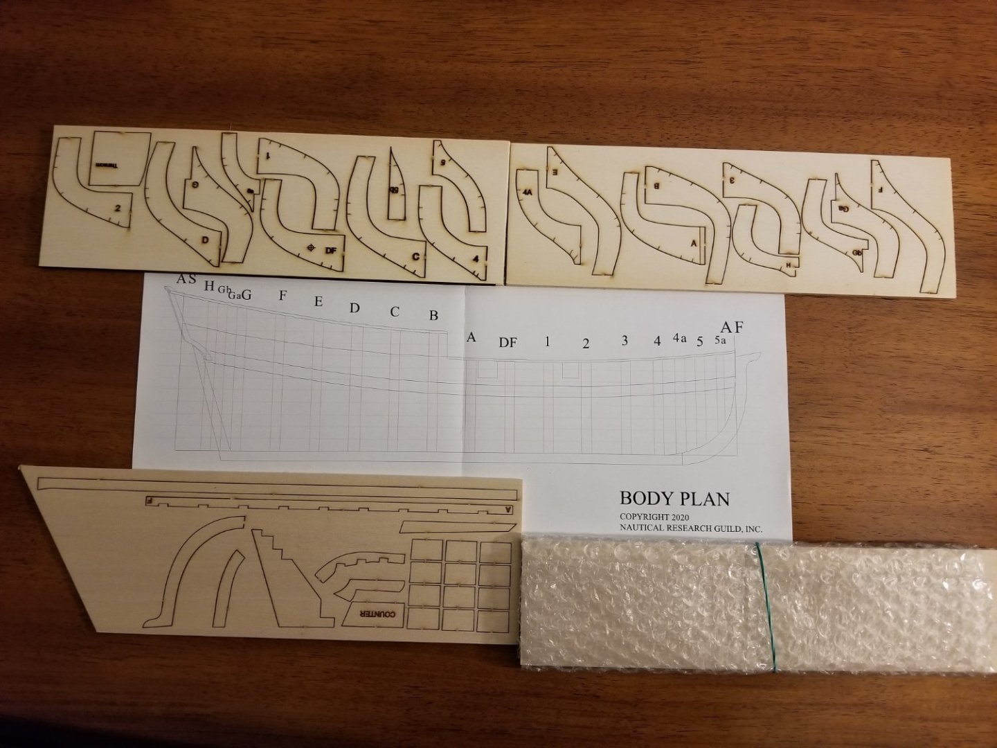
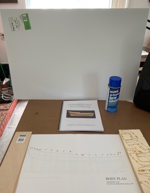
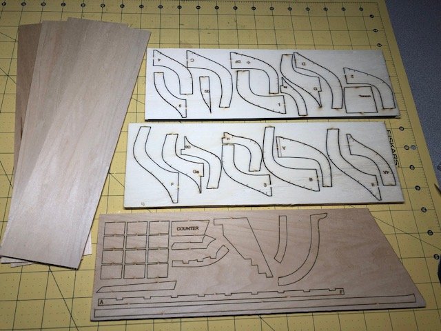
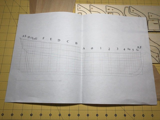
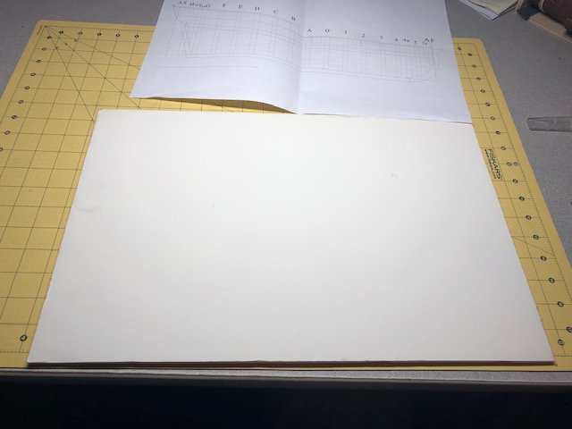
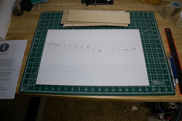
 Hi all, This is my first build log. I didn't discover this site until I was nearly finished with my first build, the HMS Terror. I am planning to post pictures of the Terror in the "Completed models" section. A quick introduction... I am new to the hobby with about one year of experience but that one year has been a lot fun and a lot of learning. I am really diving in and am very interested in making historically accurate models. My next project, AL's HMS Bounty, is one that I plan to do a lot of kit bashing and hopefully producing a historically accurate model. I am still a working guy and I find time in the evenings and the weekends to work on my projects. I also own a boat and spend a lot of time on it. I joined the NRG a few months ago and am learning from all of you! This half hull project will help me be a better, more historically accurate builder! So, here we go! I received the kit about a month ago but didn't get going on it until today! The kit came well boxed and wrapped in material to prevent damage from occurring, especially to the planking material: Inside the plastic bag are three pieces of laser-cut plywood, one with the frames, etc and one with the keel sections. Wrapped in the bubble wrap are four sheets of basswood: Also, included is the plans - a single piece of paper: The nice folks at NRG emailed the instructions to me in a separate email. I'll be following these to the letter! Or at least trying! The first thing to be done is adhere the plans to a working board. I happen to have a piece of 1/4" foam board laying around and I decided to use it for my working surface. I have a 3M spray adhesive and chose that for my glue: Once the glue was tacky enough, I laid the plans down and smoothed out ensuring there were no wrinkles or bubbles: ...and trimmed the edges of the board to match the plans: Next, I removed the keel sections and laid them out on the plans. The pieces have not been cleaned up or the char removed yet. That's it for this post! I know that there are two other build logs on the site, one from the original builder and one other. I hope that my log will show something different that will help others down the road. More to come!
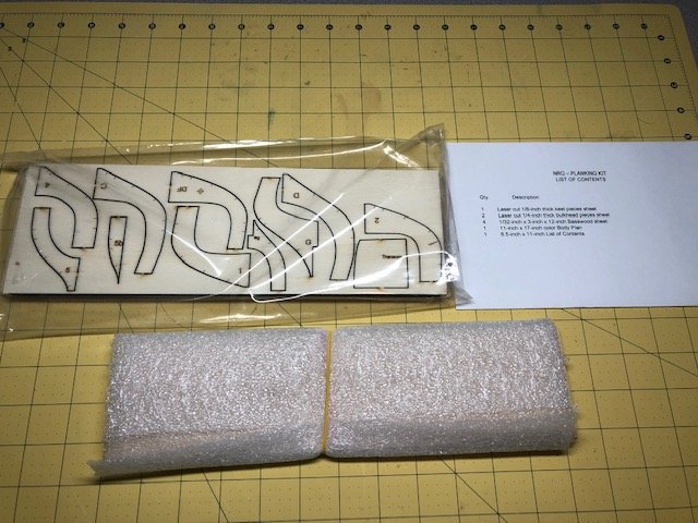
- 44 replies
-
- 7
-
-
- half hull planking project
- half hull
- (and 2 more)
-
 I ordered this kit as soon as it was released but I wanted to finish my Sharpie before diving in. Of course my father found a small boxcar kit that I was hoping to put together first, but since that kit was incomplete I plan on starting this half-hull in the meantime and learning how to plank (hopefully that will set me up well for my next full ship the Alert). So far all I have done is setup my build board: The instructions suggest using 1/4" foam board, I had a sheet of 1/8" so I cut it in half and glued it together (hopefully all my issues are this easily solved 🙂). I trimmed the board down to the plan sheet and applied tape around the edge to stop bits of foam from following me everywhere and to make certain that the plan was firmly secured to the board (I did first glue it with Elmer's craft bond spray adhesive). Currently I'm sanding the edges of the keel, keelson, stem, deadwood and stern pieces to remove the laser char.
 -
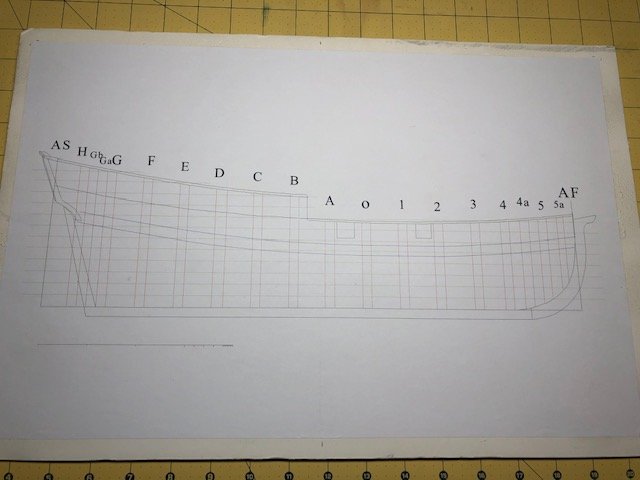
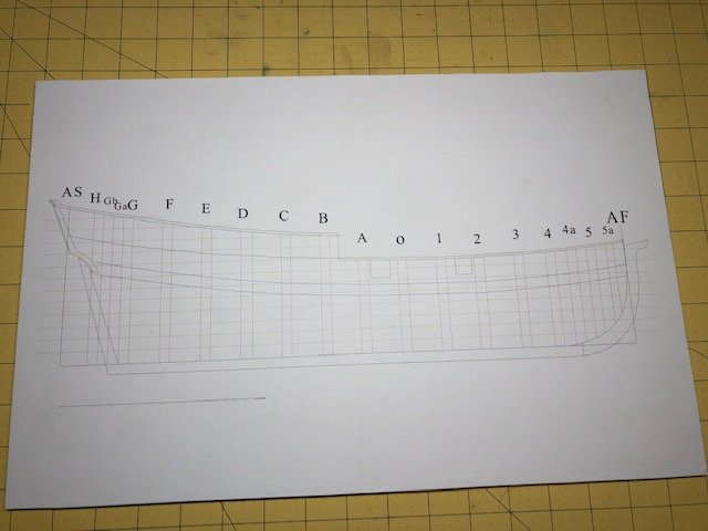
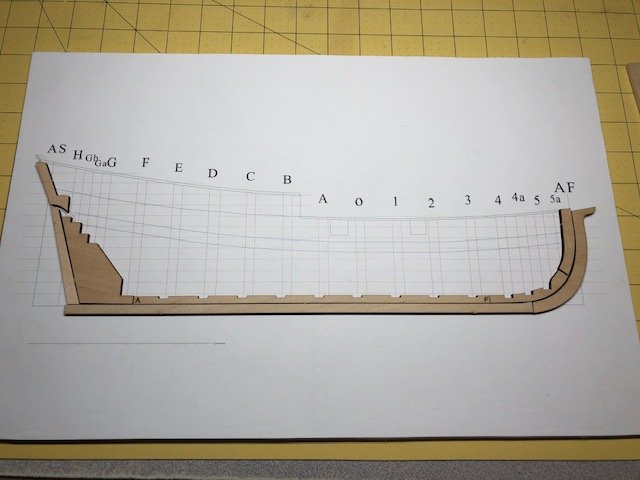
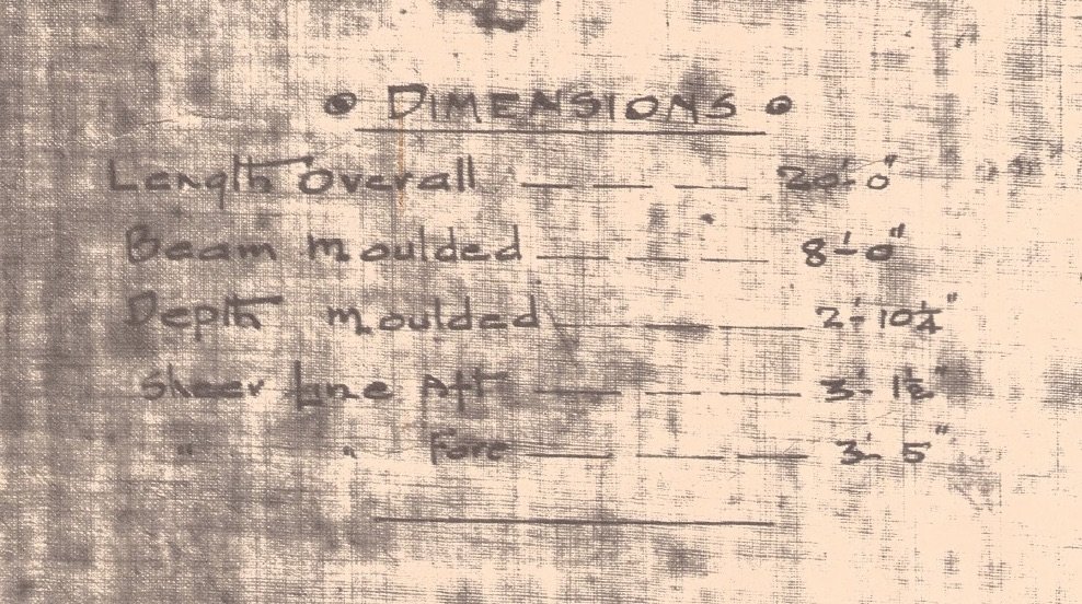
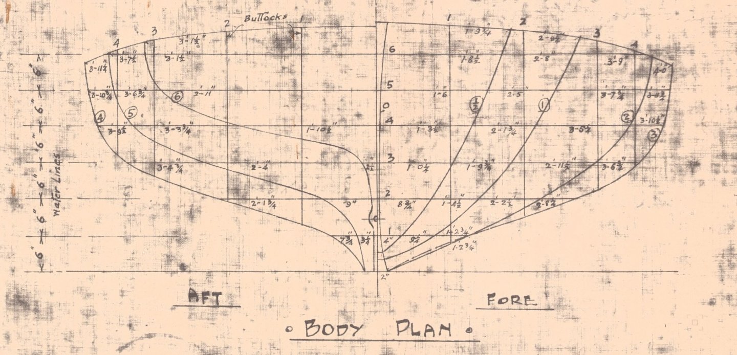
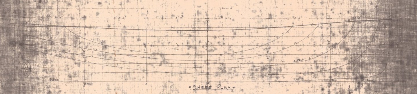
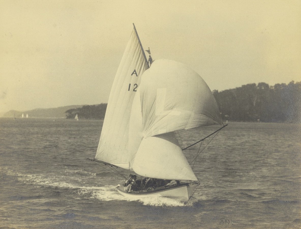
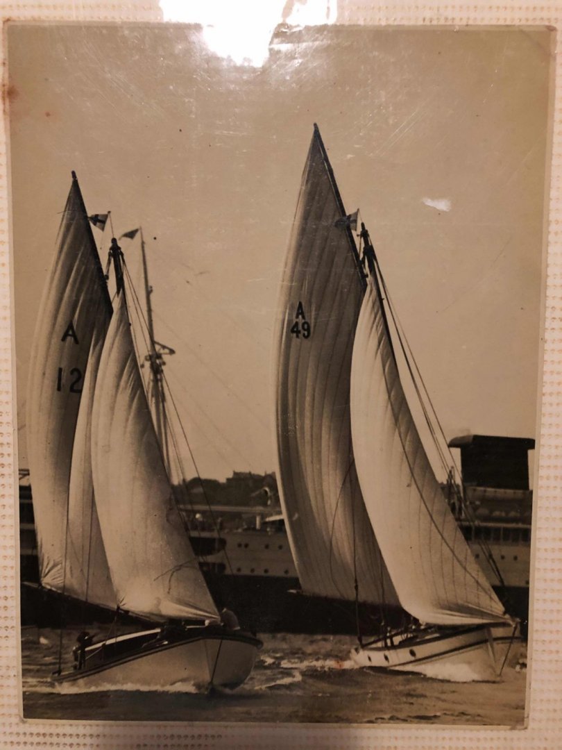
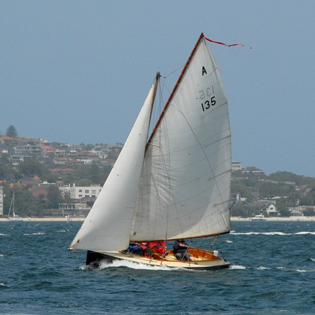
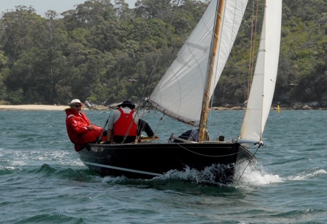
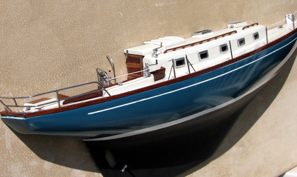
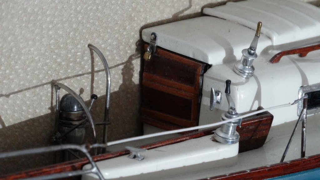
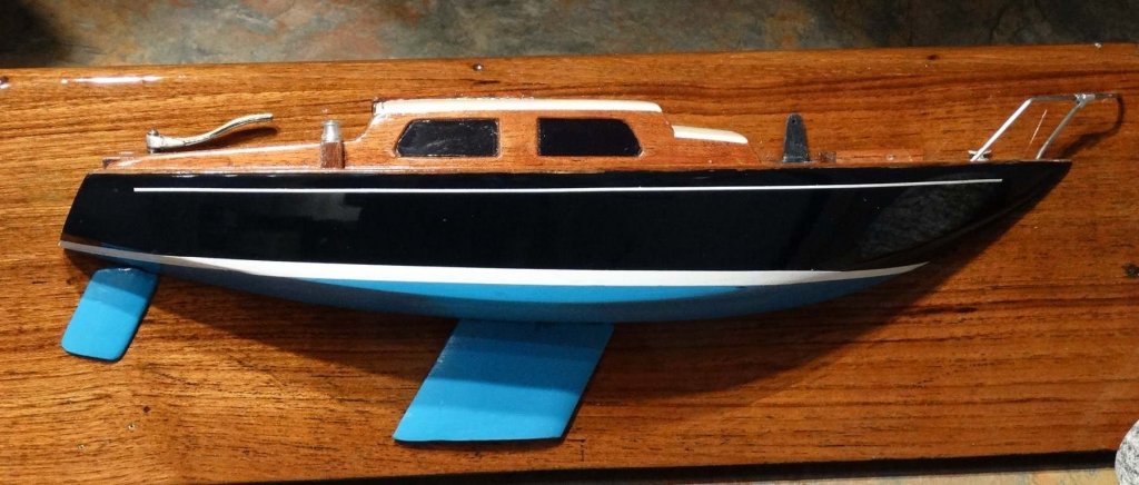
 Hi everyone This is my second venture into model boat building. The first model was an unbuilt yacht design by a Sydney amateur yacht designer; this one is a much earlier design by the same man - E.C. "Cliff" Gale. Karoo was a 20' open sailing boat with a bowsprit & gaff sloop rig. Karoo was raced & was also a family boat. Incredibly they (Cliff & Mrs Gale, plus 3 strapping young sons) used to pack her full of gear for holidays & spend a week or two aboard on Pittwater, Broken Bay & the associated waterways Cowan Creek, Coal & Candle Creek etc. I'm doing a half model of the boat, as a gift for our sailing club model wall. The Karoo was a quick boat, I know because a copy was built about 20 years ago & despite her being given a fairly conservative sailing rig she is well able to keep up or beat with larger yachts. As with the last model the drawn information is not complete, but there are some photos of the original boat. And also I have one of the sons - Bill - who at 95 or so still has an astonishing memory when it comes to yachts. The drawing would have been done from a design half model, Cliff shaped the design in a bread & butter half model, layers dowelled together, & separated them to get the drawn lines. I plan to show some details beyond just the hull: gunwale & toe rail, lower section of the mast, bowsprit, rudder & tiller, centreboard. Coincidentally, it was 90 years plus 10 days ago this drawing was done: The lines show a shallow dishy hull with clean underwater lines; the shape is beamy & shallow. A 40% beam:length ratio is wide, but beamy is (or was) quite common in Sydney: Here, cantering under spinnaker at Pittwater, in the early 30s: This is the rebuilt version, she was slightly lengthened & made finer in the bow. Interestingly the owner's one comment is that she tends to bury the bow downwind under spinnaker. I'm guessing the original didn't do that, or as much, with more buoyancy in the bow. On the left, A12, with a removable cuddy cabin for cruising.
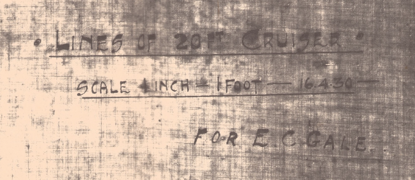

- 99 replies
-
- 11
-
-
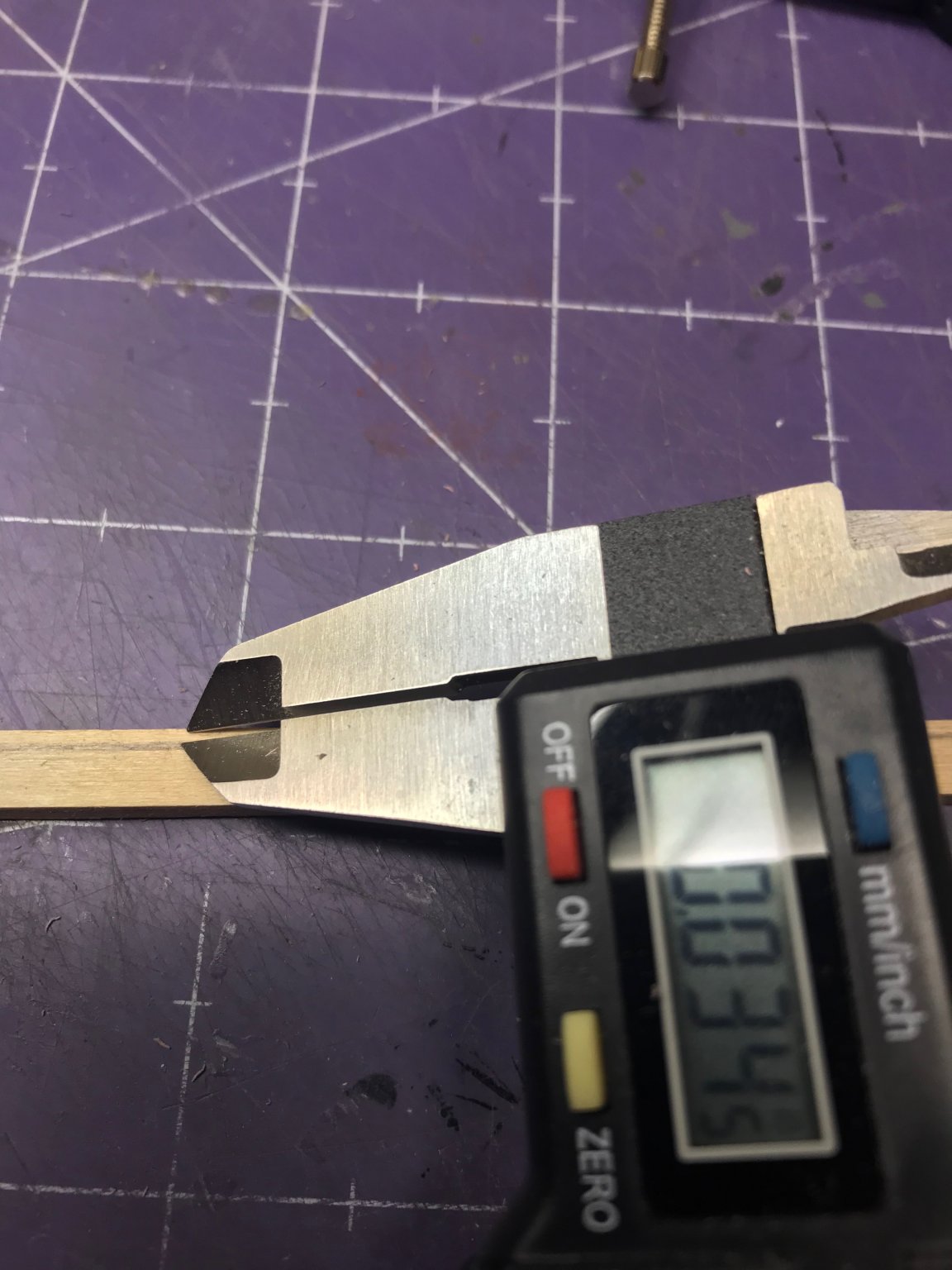
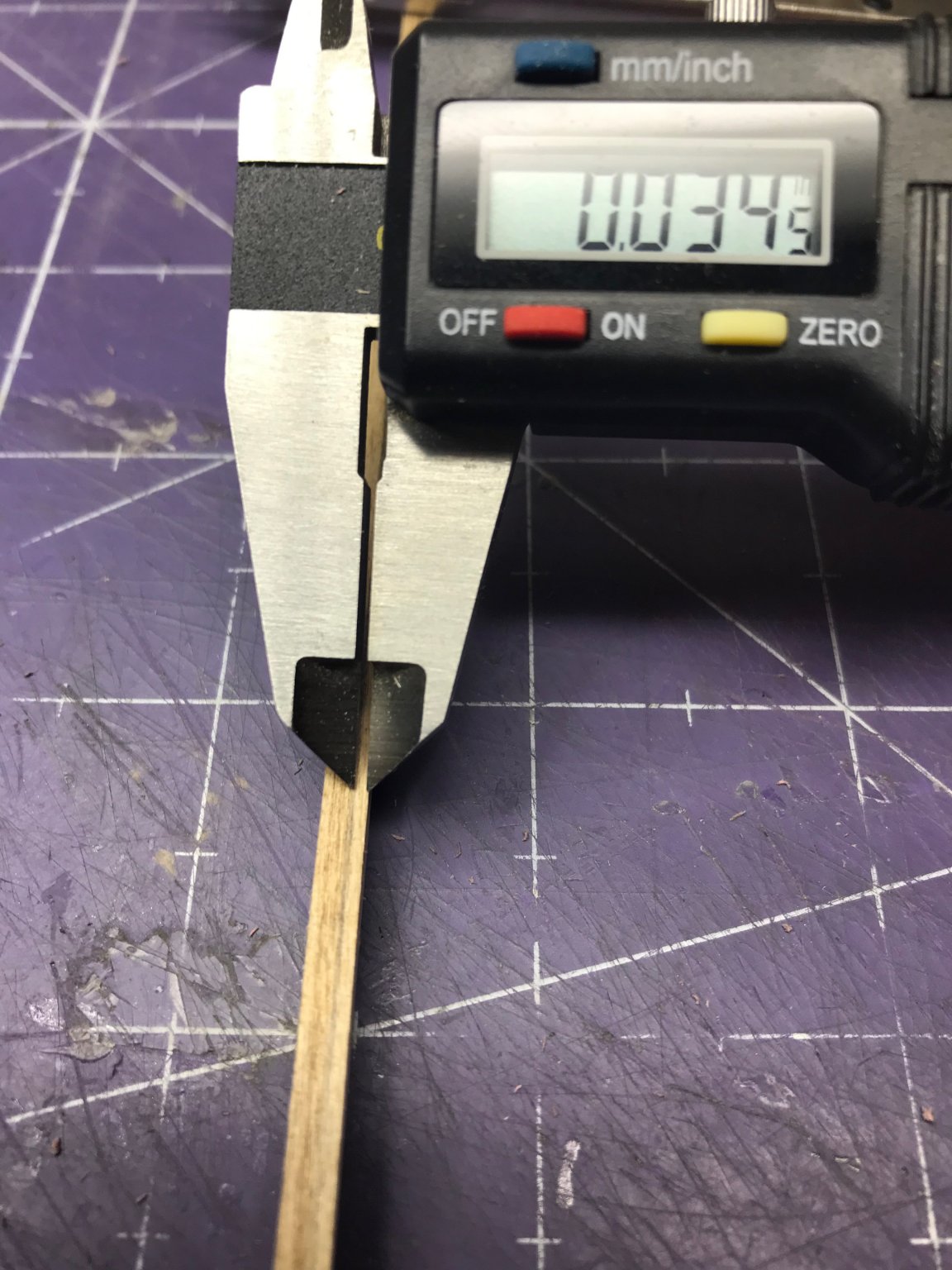
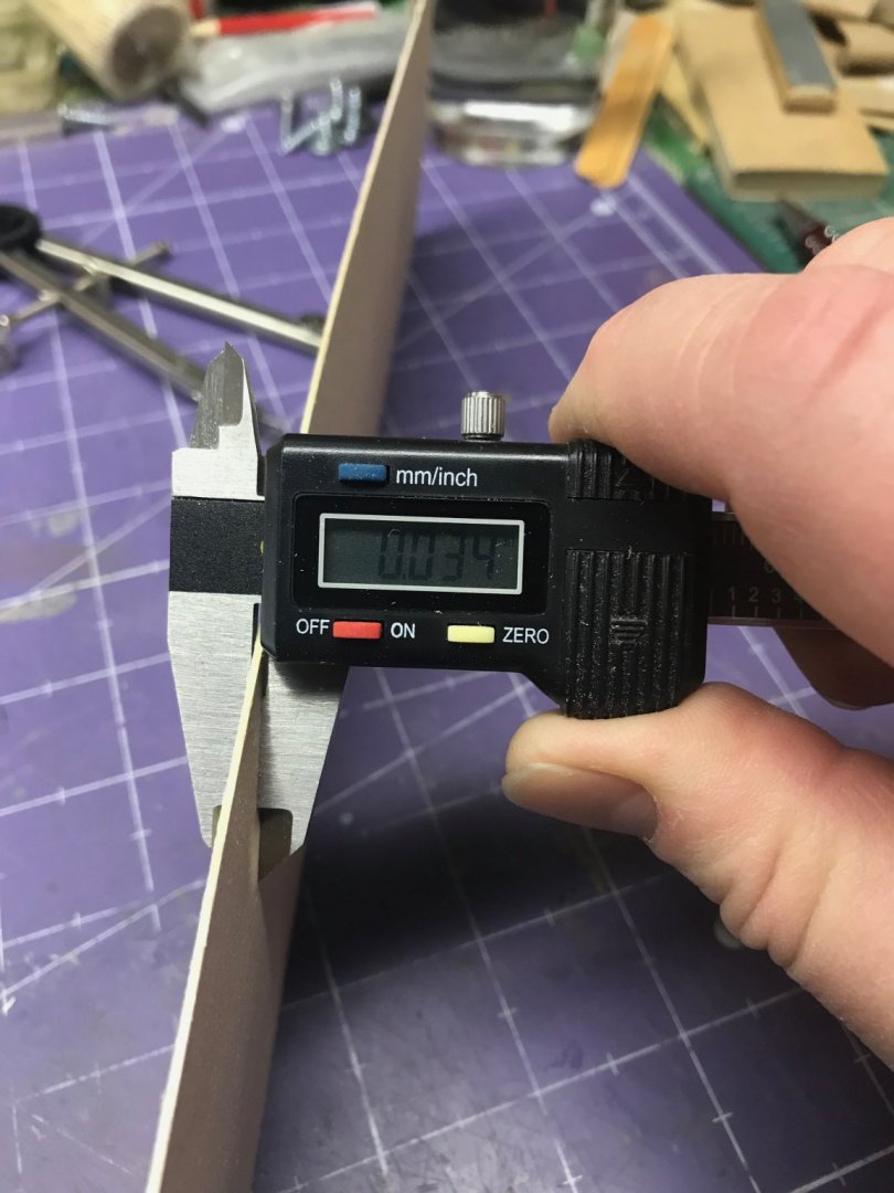
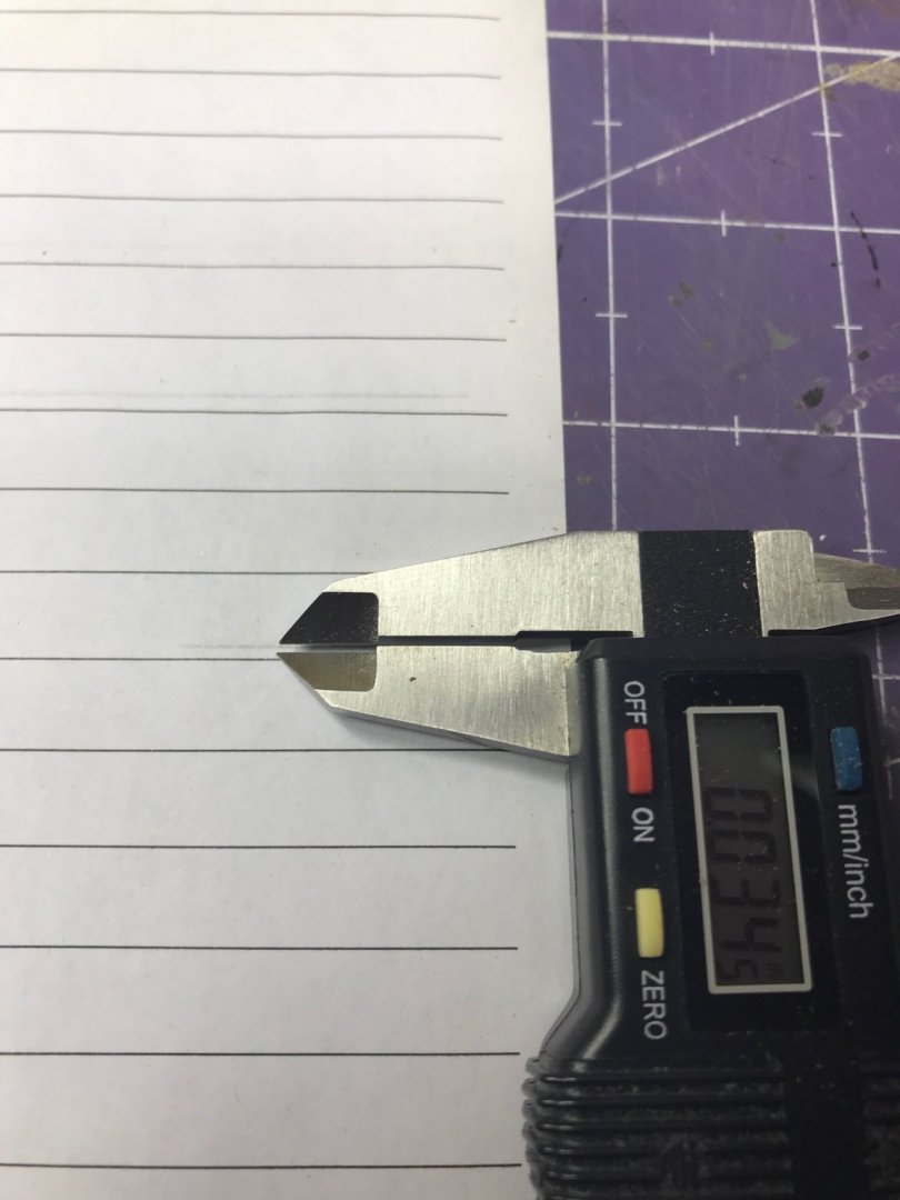
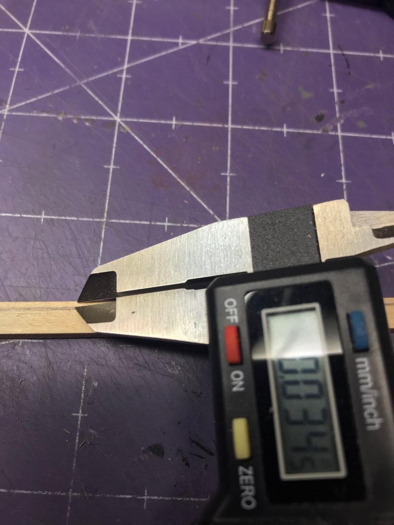
 I am the proud owner of Toni's Introduction to Planking Kit #1 and, since I've got a little time off during the holidays, I decided to get started. I started by reading the instructions. (I've heard that enough times from Kurt to know to start there and it's mentioned in Toni's instructions. It's good advice and I found, even reading through them, I made at least one error early on.) I mounted the plans to a piece of foam board, as instructed. Then I laid out the keel, keelson, stem components, deadwood and sternpost on the sheet to understand how they all fit together. Next step is to cut the rabbet. I'll confess I read this section multiple times and Toni's posts here on MSW, which are slightly different from the instruction manual I have. I'm hoping I got this part right. Toni says, "Measure the thickness of your planking. On this model I used 1/32" basswood which actually measured 0.43" thick." I had to think about that for a minute. 1/32" is 0.03125", quite a ways from 0.43". Then I measured the planking material in the kit: I think this is a combination typo and a little dyslexia. The instruction manual should say 0.034" instead of 0.43". Doesn't matter. I figured it out and understand the point. You need that measurement to transfer it to the keel components, which I did. I did a little experimentation to make sure I drew an accurate line on those components. I set my compass, drew a line on some scrap paper and then measured it with the caliper. I had to do that a few times to adjust the compass properly, but it paid off. I drew lines on both the outboard and top edges. (This is something Toni didn't say to do, but it made sense to me. It the angle is supposed to be 45°, then you need to know both sides of the right triangle to get the hypotenuse right ... right? I have just a couple of observations. First, scraping the char off the components is a necessary task, I know, but I would urge people to take their time with it. I could have used power tools to do this or gone after it with some really coarse sandpaper, but I used the back of an old X-Acto blade as a scraper. It worked great and I didn't risk damaging the components. It took a little longer than other methods, but I think it was a good call. For cutting the rabbet, again, I could have used power tools for that. I decided not to and I'm glad I did. (Toni designed this kit to be done by people without access to all that stuff, so it's not necessary.) I used the X-Acto blade again and then some sanding sticks to finish it off. That worked very well and, although it took a while, the results were better than I think I could have gotten with power tools. Small planes would have worked too. I tried to use mine, but found they were a little too aggressive and thought if I used them I might inadvertently take off more wood than I wanted to. And no project would be complete without some errors. Even though the instructions are very clear about how far aft to go with the keel rabbet -- Figure 10 shows how far to carve it -- I still carved it all the way aft. I corrected that right away by gluing in some scrap wood and returning the keel to a square profile. Best thing about a wooden ship model: there's nothing you can't fix. Here's the final product. Now on to the frames. Per the instructions, "the slots on the keelson were laser cut approximately 1/16" too shallow to help prevent breakage of the basswood keelson while making the rabbet." So I need to deepen them that 1/16" which will bring the distance between the bottom of the frame and the rabbet to about 1/16". Off to the next step! Dan
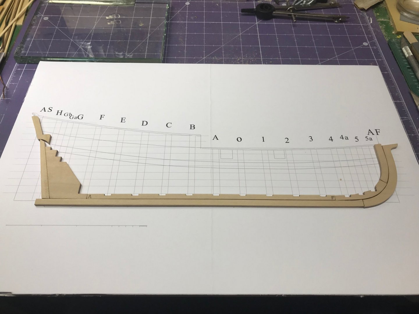


- 39 replies
-
- 10
-
-
 Taking a short break from the Harvey build until the wood I ordered arrives. I had planned to build the half hull before I started the second planking layer on the Harvey - I'd really like to do it right! Kit arrived in perfect shape, and I printed out the instruction manual. I've been reading through Toni's build log and think I'm ready to go. I mounted the plan sheet to the recommended foam board using Elmer's spray adhesive. No wrinkles Started sanding the laser char off of the pieces. It looks like I will need to trim the stemson to get it to align with the bulkhead locations. Has anyone else found that? Will keep on sanding... that's all for now.
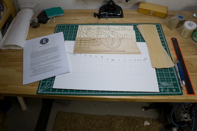
-
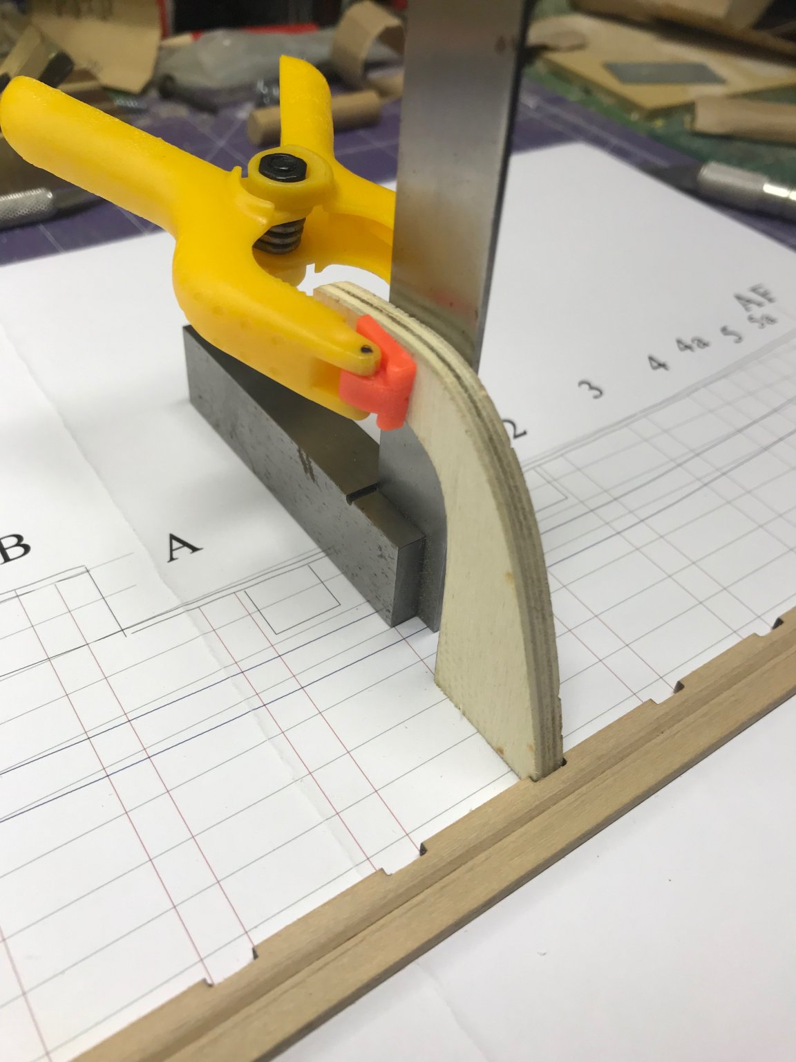
 While building my first boat kit (Chris-Craft) I had a hard time doing the planking, I discovered that a straight plank did some unexpected things at the bow of the boat. I was frustrated and knew I’d have to figure out planking. I came across the Half Hull Planking kit when searching the forum for planking information. I previewed the instructions and realized I didn’t know the terminology. The instructions identify the names of the laser cut parts but there were a number of terms in the documentation that I didn’t know. I found an illustrated glossary of ship terms (it is helpful): https://www.oxfordhandbooks.com/view/10.1093/oxfordhb/9780199336005.001.0001/oxfordhb-9780199336005-e-48 I previewed builds by tlevine, dcicero, modeler masa, and LyleK1 and I’ve been referencing those builds during my build. The kit comes with laser cut pieces to build the frame structure and planking material you cut for each plank. The instructions are a PDF file; the instructions are well written and explain concepts to understand how wooden ships are built. The kit includes an 11x17” print that shows the location of the structural parts along with other significant lines. I mounted the print on a piece of art board but I quickly discovered that I wanted to cut the size down to accommodate the use of clamps during parts of the construction.
-
 Well, I decided to invest in a side project developed by my ship club mate, Toni Levine (@tlevine). Since my last post on my Syren build log, I've made more progress in some basic techniques of manipulating the planks. Specifically, I received an old plank clamp which was the property of Steve Wheeler (we all miss you, Steve). Hopefully that will take some of the plank trimming frustration away...so far it works great on a few trial planks. In the interim - I've received the NRG tutorial kit. Like others who adopted this side project, I wasn't really sure where to put this build log, so stuck it where others have - hope that's ok. If this turns out, aside from gaining a bit more confidence, I plan to mount it as a wall hanging and make a present out of it...but have to wait and see the final result. Pics to follow... Moving on!
 -
 As a preliminary caveat to this log, please understand that the builder is a novice, and that numerous searches online for a faithful half-hull rendering of Old Ironsides have turned up few usable results. I deeply appreciate advice, and most of those who read this will probably be able to teach me something I don't know! This build log is for a half-hull rendering of the USS Constitution. I am using the AJ Fisher 1:96 plans, scaled down by 50%. The plans were purchased from the owner of the company, who gave me his permission to make a reduced copy for this purpose. I will be using a "lift" method of construction, with an appended keel, sternpost and rudder, and stem. The degree of ornamentation beyond that is still undecided. I plan to make two models of this sort - the first is a prototype and a test using Douglas Fir from Home Depot - I have given myself permission to make as many mistakes as needed in planning, build process, and execution on this first attempt. The second model is a gift for a family member who will be retiring from a lifetime of building ships for various companies, most lately the US Navy. All of us have had a "favourite uncle", and it's a delight for me to make something meaningful for mine. Our family comes from multiple generations of shipbuilders in New Brunswick, Canada, and model shipbuilding is my way of keeping that craft alive for my own children - albeit in a far humber fashion. So, with that said, on with the Log! ***Edit: It turns out the AJ Fisher plans are 1:96, so this is actually 1:192 scale. My apologies for not checking before posting! Edited the topic title as well.
- 23 replies
-
- 3
-
-
- constitution
- frigate
- (and 1 more)
-
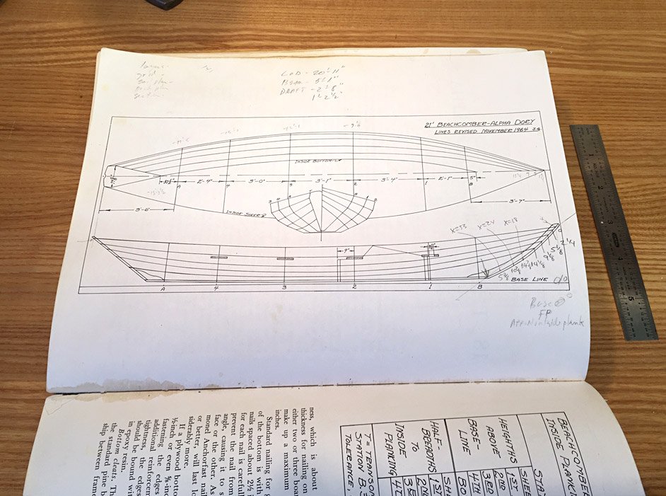
 I’d like to recreate the build log for a planked half model that I posted a few years ago on another forum (not a model forum). I’m rewriting some of the text, and copying and pasting some of the text from the previous post. Pardon me if it sometimes appears a little disjointed. I've long been fascinated with the Swampscott type dories of Boston's North Shore, and I have considered building one out at my boat club. Years ago, I drew up a portrait of the sail plan for the Beachcomber, an exceptional boat from William Chamberlain's shop in Marblehead. I'll get bogged down if I try to describe it all here, so I will refer you to an article I wrote for my club newsletter. http://jimluton.com/dorymod/beachcomberarticle.pdf Below is the cover of a nice book, with Chamberlain's beachcomber on the cover. The lines, table of offsets, and construction plans for this boat are published in John Gardner’s “The Dory Book”. The half model is set up with half molds on a flat board (1/8" poplar ply), sawn to the boat’s profile shape, that represents the hull centerline. That profile shape is then mounted to a piece of MDF to keep it flat. I used 1-1/2" = 1'-0" as a convenient scale. The model is a manageable size (the 21' boat is about 32" long), and scale planking is relatively easy to come up with. 1/2" planking translates to 1/16". For this I used a sheet of 1/32" aircraft birch, which I cut in half and vacuum bagged together to make a 1/16", six ply sheet. The molds are cut from 1/8" Italian Poplar ply. The 1" thick transom is 1/8" mahogany, etc. etc. I already had the body plan drawn to scale in the computer, so I printed out the individual sections and glued them to the 1/8" ply mold stock, then cut them out and faired them on a little belt sander table. The molds and transom are each glued to the profile board in their respective positions, corresponding to their position on the lines plan. I used cyanoacrylate for this, as for the whole project. I mounted the profile board to a piece of MDF with an "L" shaped block on the back to facilitate clamping in the vise in various positions. I I'llI I'll stop here for now, and pick this up tomorrow. Time to work on the sharpie. Thanks for looking! Cricket
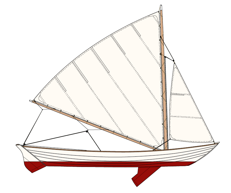

- 1 reply
-
- 3
-
-
- beachcomber
- dory
- (and 2 more)
-
 I'm joining the fun of this "learning exercise". Started: Using a foam core building board. Rabbet cut. (Without much thought I started cutting the rabbet on both sides of the keelson before I remembered that this was a half hull - oops)
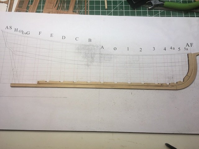
-
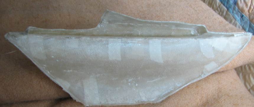
 Planking a hull is still something of a mystery to me, as I am sure it may be for some of you. In the past I successfully planked two POB hulls with the help of very detailed practicums writen by outside sources. Despite that I in no way would I say I am proficient or even confident in my abilities. Thats why I am so excited about this build. It is designed specifically as a hands on kit that will teach you step by step how to plank any hull properly not just this kit specifically. It looks like it will be very educational as well as fun. It also makes a very nice looking finished ship model. I plan to mount mine on a nice board to hang on the wall once finished. I am hopeful that once finished I will have done more then learn but will walk away with new confidence that I can take any kit or scratch built hull and do a reasonable and historically accurate job of planking. The kit comes from the Nautical Research Guild (NRG) as shown. The kit is very reasonably priced in my opinion at $65. It includes a very nice PDF building manual from NRG sent to me via email. I printed the manual at home then took it to the print store and had them cut and spiral bind the pages. This cost $3.20 and is well wort it. It keeps the manual organized and it will open and lay flat on my table as I work. It also includes a detailed tools list. Another nice thing with this kit, it doesn't require anything special in way of tools. in fact just some basic tools that anyone coming into the hobby would want to purchase or in my case already own. I have glued the plans which come with the kit to a piece of 3/16 foam board. This will serve as a building board. Thats all for now. I know it isn't a great deal to see at this point but I wanted to at least get this build log started. I am hoping that this and other logs will lead the way and help to generate some excitement for this kit.
-
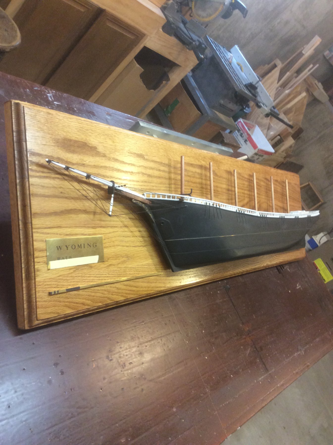
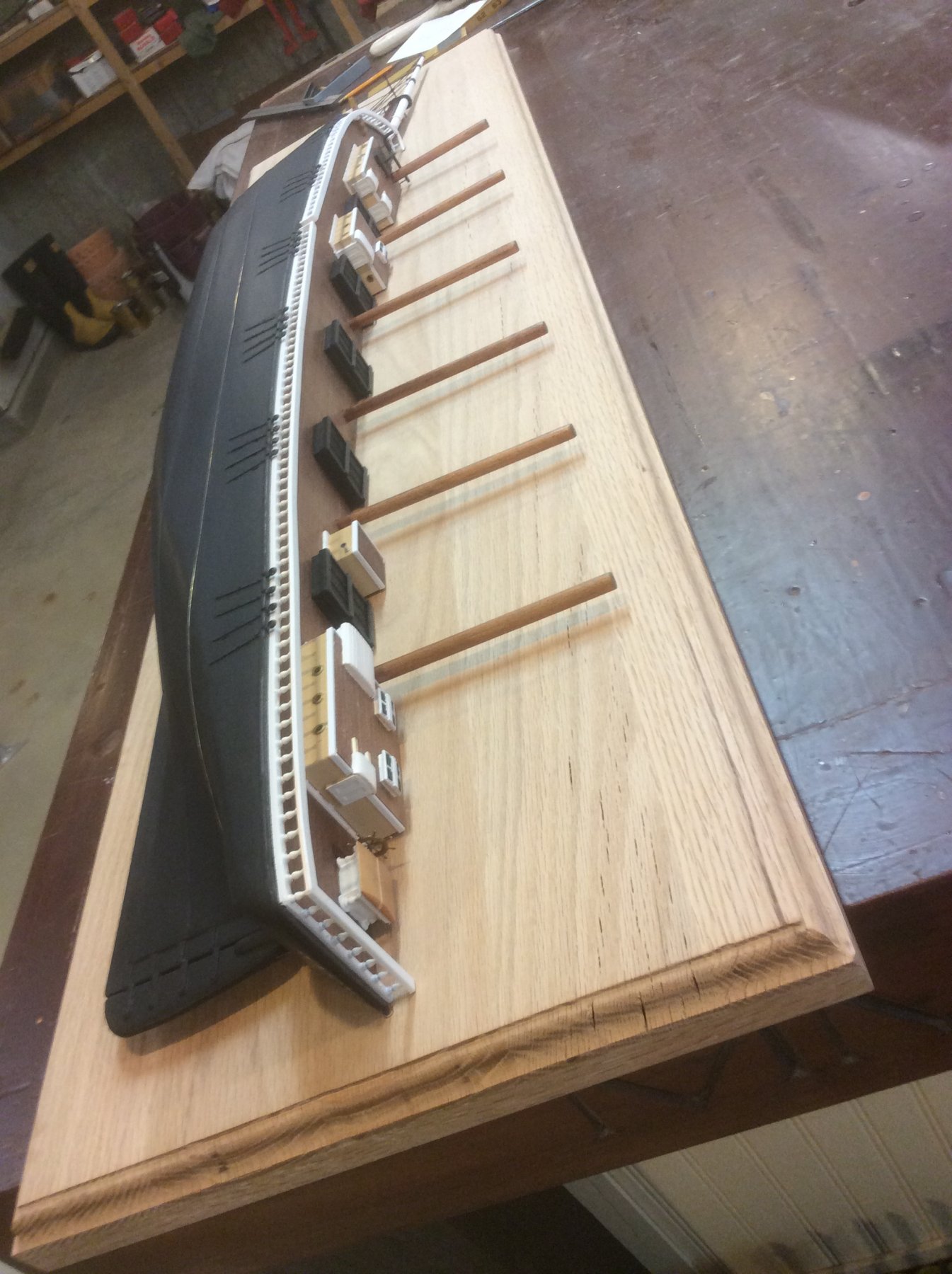
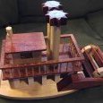
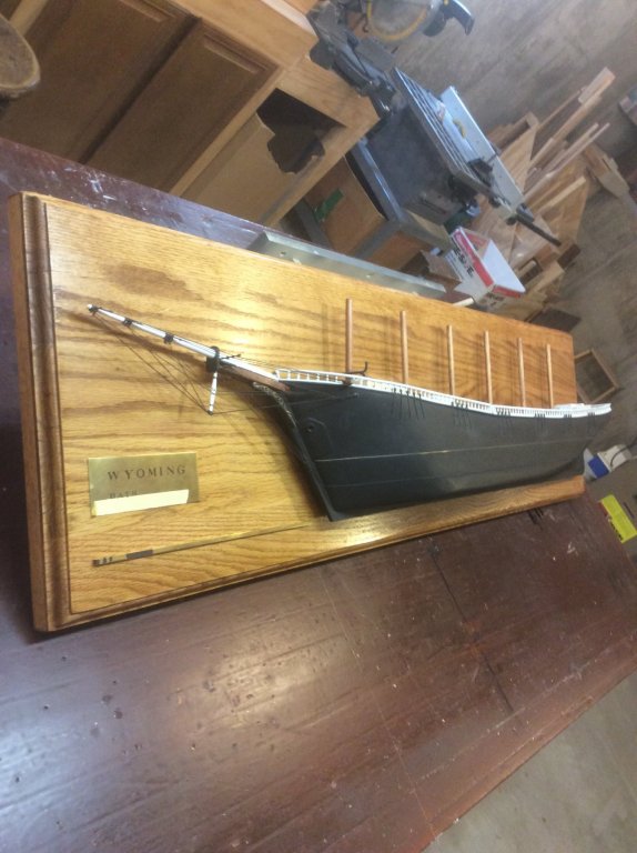
 This is my first scratch build log, and it will certainly not be up in the rarefied company of many of other members scratch build logs, but still may provide some interesting information, techniques, and entertainment. This project has its genesis in a passing remark made by an in-law. Some time ago, I scratch built a half hull model of the six masted schooner Wyoming based on drawings I obtained from the Maine Maritime Museum. I did so because I wanted to get an a better appreciation of just how big she was. I was happy with the results, but, at nearly five feet long, the Admiral had objections to where she was going to hang (the model, not the Admiral). Knowing that my son’s in-laws just completed a home addition and we’re decorating with a nautical theme, I thought, “Hey, they’ll really like this!” And, so they did. During the unveiling of my “gift”, my son’s Father-in-law mentioned that his father had been a captain in the merchant marine of the Fra Berlanga. As it happened, due to many unfortunate events in family history, the only memento he possessed of his father’s, related to his ship, was a photo similar to the one attached to this log. He said he wished he had a model, similar to the Wyoming, of Fra Berlanga. That was my que ... “I’ll make you one”. Thus begins my adventure.
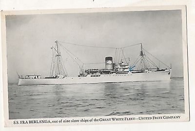

- 14 replies
-
- 6
-
-
- fra berlanga
- banana boat
- (and 2 more)
-
 Searching for a good place to start this..and since I will be building wood half models of at least 8 clipper ships..this looks like the right place. I have several builder half models of several clipper ships..ie...the Lightning and the Cutty Sark. But my problem is, in all the clipper models I build they are all roughly the same size models..but do not represent the actual comparative size to each other. To keep the scale issue from being clouded as folks view my collection..and from misconceptions being formed that this ship was the same size as that ship; I am embarking on a new project. To scratch build from carved wood a plaque that will contain some significant clipper ships through the period from 1845 to 1869. A representation of the evolution of the clipper design. As far as I am aware...there is no such collectors plaque currently available...so I am taking it upon myself to design and build one myself, for my library. This means I will draft and scale 8 clippers...that I feel represent significant design changes and establish a visual representation of scale between these clipper ships. I'm first starting with the Rainbow..of 159 ft built in 1845. The Sea Witch of 170 ft built in 1846. The Cutty Sark of 212 ft built in1869. The Flying cloud of 229 ft built in1851. The Young America of 243 ft built in 1853. The Sovereign of the Seas of 258 ft built in 1852. The James Baines of 266 ft built in1854 The Great Republic of 335 ft built in 1853 Each one of these clippers represents different designs and sizes...just what I want to demonstrate. The average clipper's size fell between 170 and 260 ft in length....so I selected vessels that fell within that norm. Not to be eclipsed by the Giant of them all the Great Republic. I will be carving each of the half hull models from soft pine and the scale selected for rooms sake will be 1": 35'. So the Rainbow will be roughly 4 1/4" long and the GR 9 1/4". All will be situated in row on a nicely detailed plaque of wood(Painted antique green) with gilded trim. Lets get started. Rob
 -
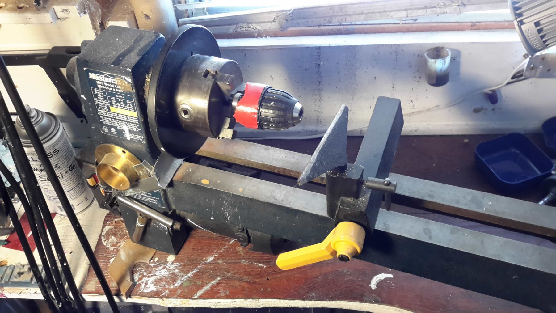
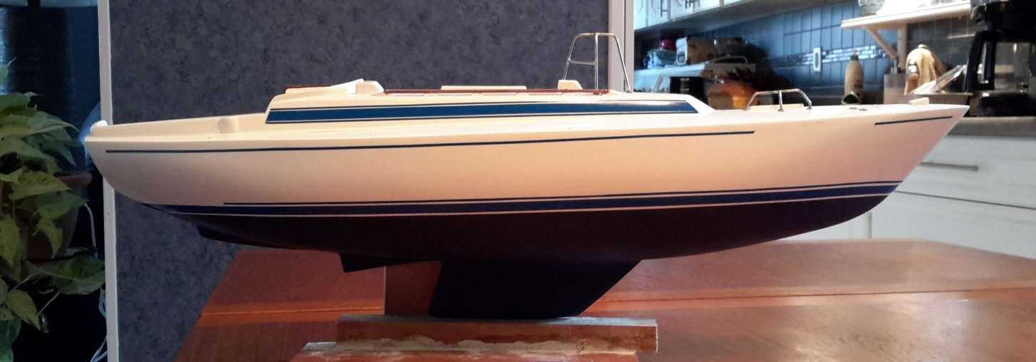
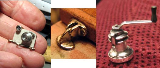
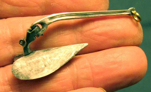
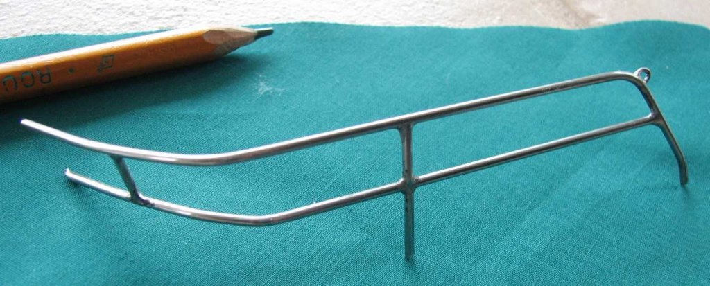
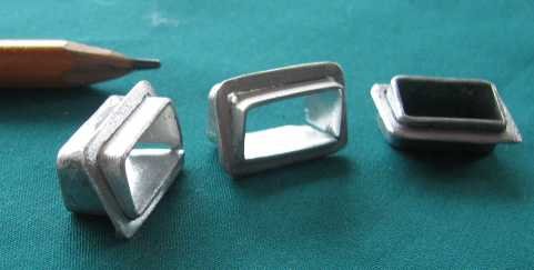
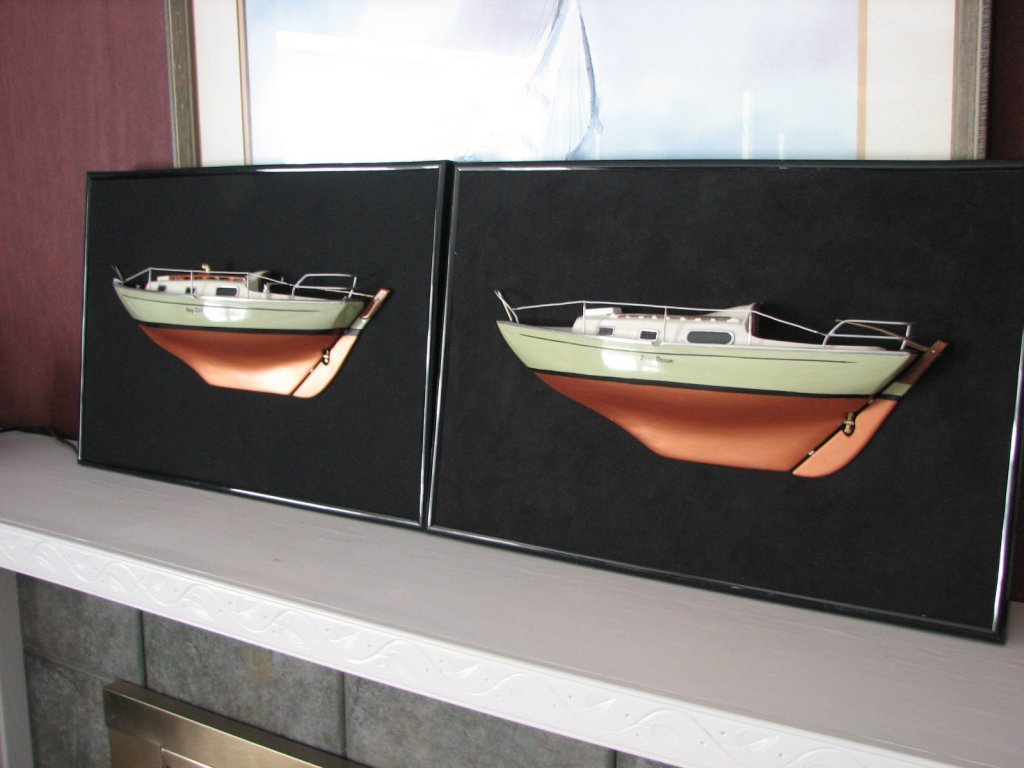
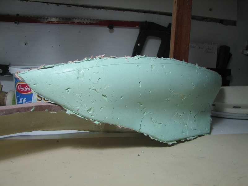
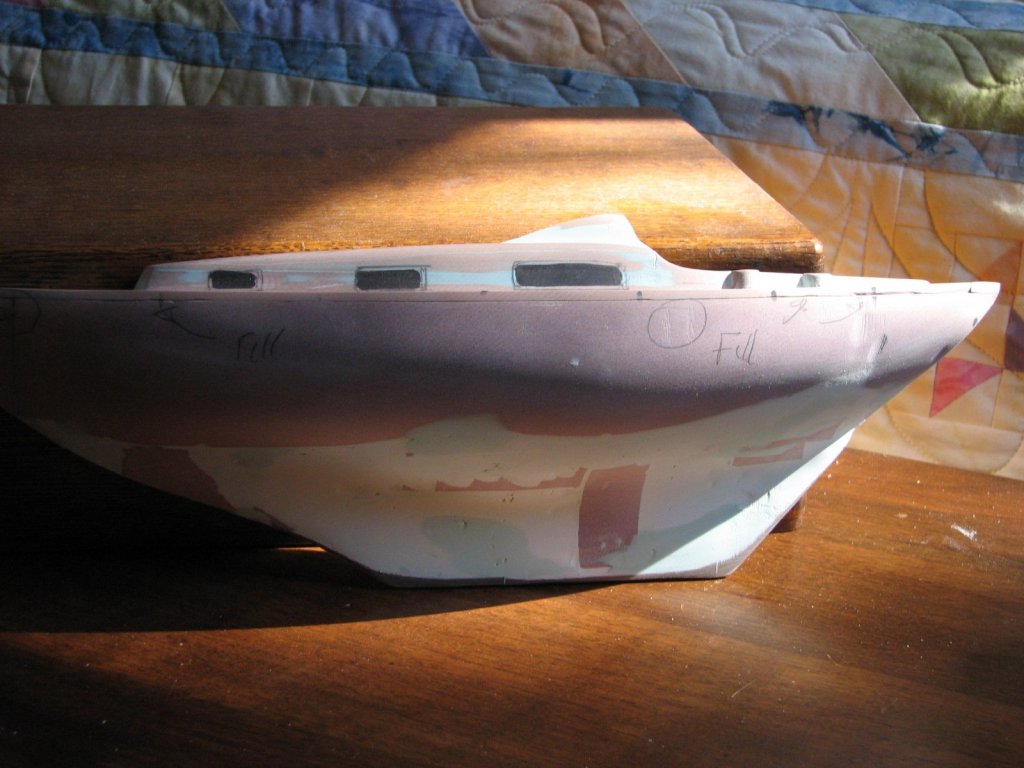
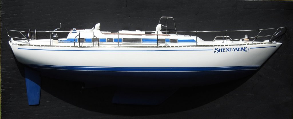
 Here are the last of my maritime models and, in keeping with my different style of building, they're all half hulls. I like this format as it can be hung on a wall so I don't have to answer that awkward question from my wife ... "And where do you intend to put THAT". Well, it's an easier discussion! First up is a model of our own boat, an Alberg 37, which we've since sold. Ever since I took up scratch building I had intended to build this once I developed enough skills to reproduce it and, more importantly, all the metalwork. The hull is carved out of a block of Renshape and is at a 3/4" scale. Here are a few of the details I scratch built from salvaged metals. I've had some questions asked earlier about tools so I'll digress here for a moment. My "lathe" at the time was a hobbyist wood lathe with a 3 jaw chuck, a tool rest and I used cheap Chinese carving chisels which I would grind to custom shapes as needed. In the picture above I've got a chuck that I salvaged from a hand drill mounted into the 3 jaw chuck. This is my preferred setup when making tiny pieces as it gets your fingers away from the deadly, hard, spinning 3 jaws. Even though I now have a "proper" metal lathe I miss the flexibility offered by hand held tools. Anyone considering a metal lathe might want to keep in mind that all the turned metal pieces you can see e.g.steering binnacles and winches, were made by a hand held tool and are considerably more difficult (for me) to make with a metal lathe. OK ... moving on. Next up is up is our previous boat ... a Thunderbird 26. These are plywood hulls built to a Canadian design. On the real boat I removed the cabin and cockpit when I bought it and built a totally new cabin so if anyone thinks it doesn't look like a T-Bird ... that's why. I made this simple, smaller model (13") for one of our sons who was very fond of the boat as a child. Carved from Renshape. Cockpit details mostly fabricated using Arborite/Formica samples. My wife can be very indecisive when we go to a hardware store to pick out a colour for the new kitchen so the salesman is always happy to load us up with lots of samples! These are great for flat surfaces because of their perfect flatness, square and strong. CONTESSA 26's ... Two of them. Our friends who owned it had split up and they both wanted one. Both are 12" (maybe 13") models. The original is shaped as usual from Renshape I made a fiberglass mould from the first hull to save same time. then used auto-body repair paste (Bondo) to make the duplicate. Both friends are happy with their souvenir ... but still apart. BENETEAU 51 IDYLLE This yacht was owned by friends who have it in the charter business in the Caribbean. The real one ... The hull was fashioned from Renshape (mostly) and generous applications of fiberglass paste and Bondo ... needs must. My stash was getting very low so I was cobbling together all the biggest bits to create the mass I needed. She wasn't a pretty baby. But with generous dollops of Bondo and my power sanders I soon had a suitable shape ... It is "close" to 1/2":1' scale but definitely built to scale. I'll just put in couple of shots of the build ... I won't bore you with all the fabrication that was required but if anyone wants to see how pieces were made ... let me know. LOTS of pictures available. Thanks for looking in ... Frank


- 29 replies
-
- 19
-
-
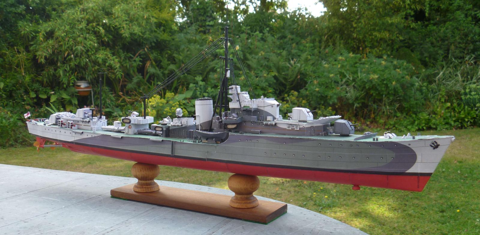
 Hi, and introduction. I was on MSW I until it sank without trace; I had several hundred posts including my build-log for HMS Cruizer. I was busted to OS and no posts when MSW II started up! I had completed Billings' Marie-Jeanne, a scratch-built Clyde puffer, and I posted my build-log for HMS Cruizer (which overrlapped with cancer, two operations and chemotherapy which slowed me down somewhat) and the free card yacht Viacosa. Since MSW I crashed I've done HMS Saumarez and the trawler Consul Pust in card (fun but frustrating, although no posts. I probably won't do a card model again. I've just given up on a card DH Mosquito - the compound curves don't work well with card). The First Lord of my Admiralty is somewhat less than encouraging, as we have a small-ish home. - comments such as "Where do you think THAT'S going to go?" gave me a hint. So the next model is half-width, will be mounted on a plank of some sort and hung on a wall - clever, eh? no space needed on top of bookcaes etc, all I need to do is get rid of that old Picasso hanging in the lounge. I've chosen as base HMS Ballahoo. It looks interesting and importantly it's a true schooner rig with no yards, so it should be safer/easier to build as a half-hull. It's going to be the port side, using the provided keel, and so the new centreline will be about 1.5mm to the starboard of centre (as the keel is 3mm ) - that'll allow me to set masts and booms with perhaps the starboard side of the dowelling sanded down to sit flat on the mounting board. I'm going to bash it a bit - I'm going to build her as a rigged half-hull commercial schooner, so there will be some departures from the base model: 1) no gunports. I'll do a continuous planked bulwark, with an entry-way probably marked out on the planking. 2) a larger, cargo, hatch between the masts. 3) the masts and yards will be full height, and rigged for centreline and port side only. I may have to smooth the masts to 3/4 width? Still to be assessed. 4) It will be finished in bare timber, varnished, possibly with a narrow black strip for the waterline but no other painting, so almost an Admiralty model! Not sure of the colour of the mounting board yet. 5) concerns about the anchor for later - the set provided seems too large, and no capstan or windlass seems unrealistic. More research needed! I've made a start by cutting the bulkheads and false deck 1.5mm to the starboard of centre - that way they'll line up with the 3mm "keel" backbone (which was gently curved to starboard, and has needed some persuasion to become straight). The bulkheads and deck and keel are glued and drying now, and I've made a solid block to mount the build on while I work on it. And of course, being a cheapskate, later I get the chance of a second model (starboard side) for free!!!! I'll try to post pictures: apologies if they don't appear, it's a while since I posted.
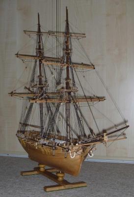
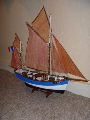

- 28 replies
-
- 6
-
-
- ballahoo
- caldercraft
- (and 2 more)
-
 Greetings, This will be the build log of the Schooner Atlantic (Half Hull). Some background history: The Atlantic was built in 1903 by Townsend and Downey shipyard, and designed by William Gardner, for Wilson Marshall. The three-masted schooner was skippered by Charlie Barr and it set the record for fastest transatlantic passage by a monohull in the 1905 Kaiser's Cup race. The record remained unbroken for nearly 100 years. Trans-Atlantic sailing record: In 1905, Kaiser Wilhelm II of Germany proposed a race across the North Atlantic and put forward a solid gold cup to be presented to the winner. Eleven boats including the Kaiser's yacht Hamburg and the schooner Atlantic skippered by Charlie Barr took part. The competitors encountered strong winds and gales which ensured a fast passage time and all eleven boats finished the race. Atlantic won, breaking the existing record with a time of 12 days, 4 hours, 1 minute and 19 seconds. The record stood for 75 years until broken by Eric Tabarly sailing the trimaran Paul Ricard. However Atlantic's monohull record stood for nearly 100 years until was broken in 1997 by the yacht Nicorette completing the crossing in 11 days 13 hours 22 minutes. Passing of a legend: Atlantic deteriorated and sank at the dock in Norfolk, Virginia. In 1982, the wreckage was removed for the installation of a floating dry dock at Metro Machine Shipyard. Tim