
James H
-
Posts
5,536 -
Joined
-
Last visited
Content Type
Profiles
Forums
Gallery
Events
Everything posted by James H
-
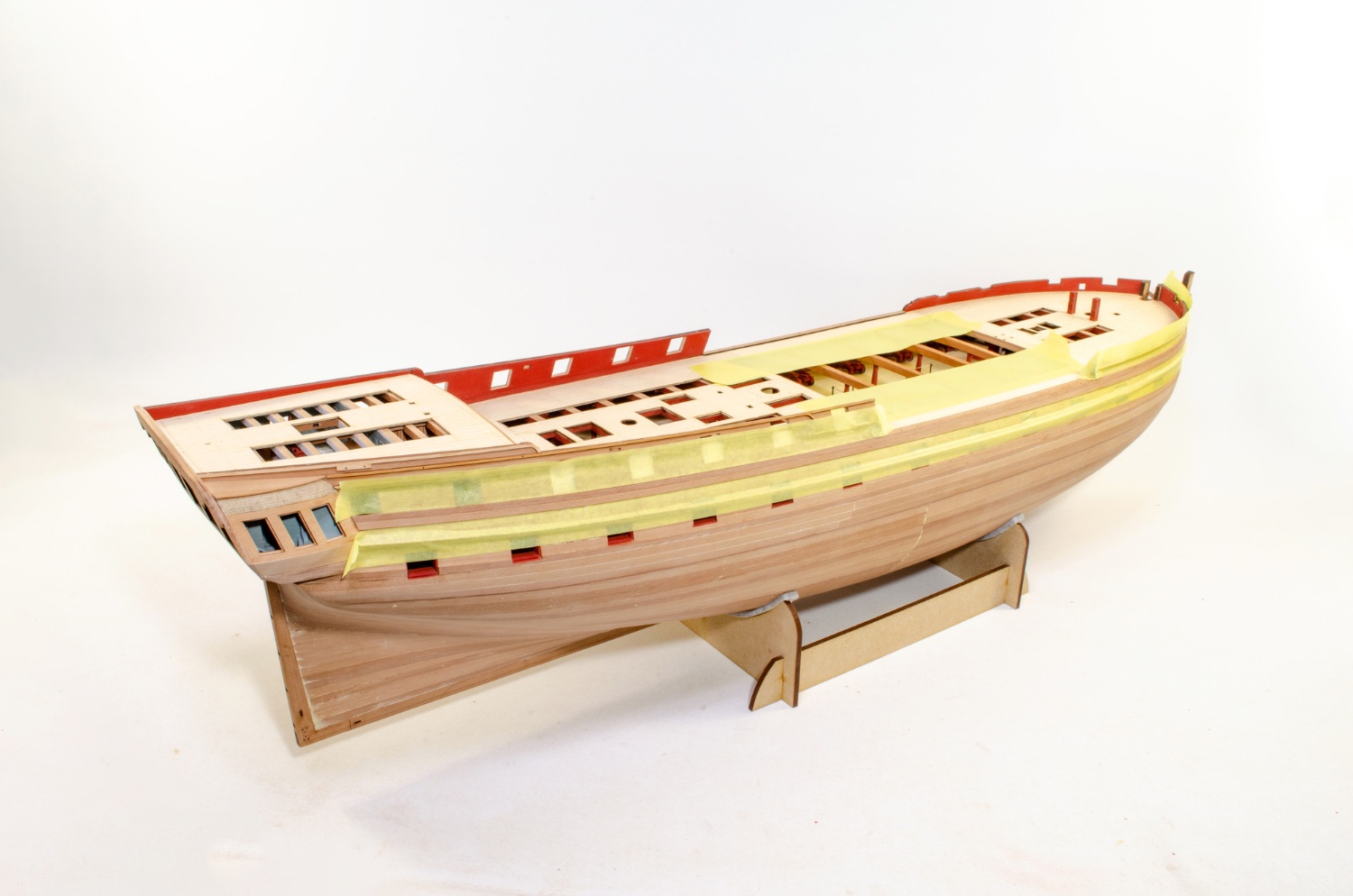
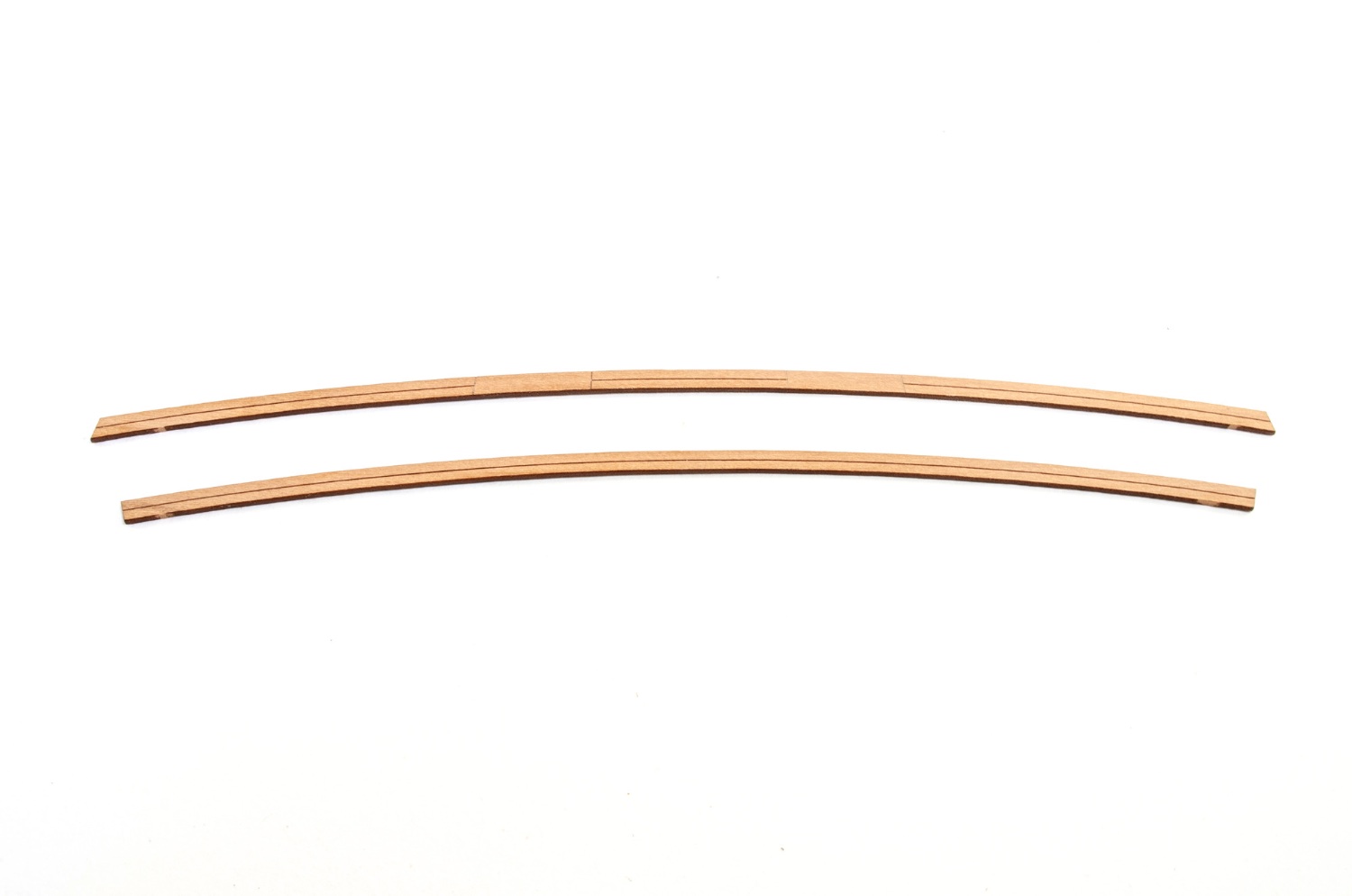
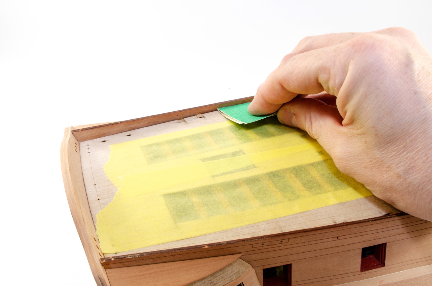
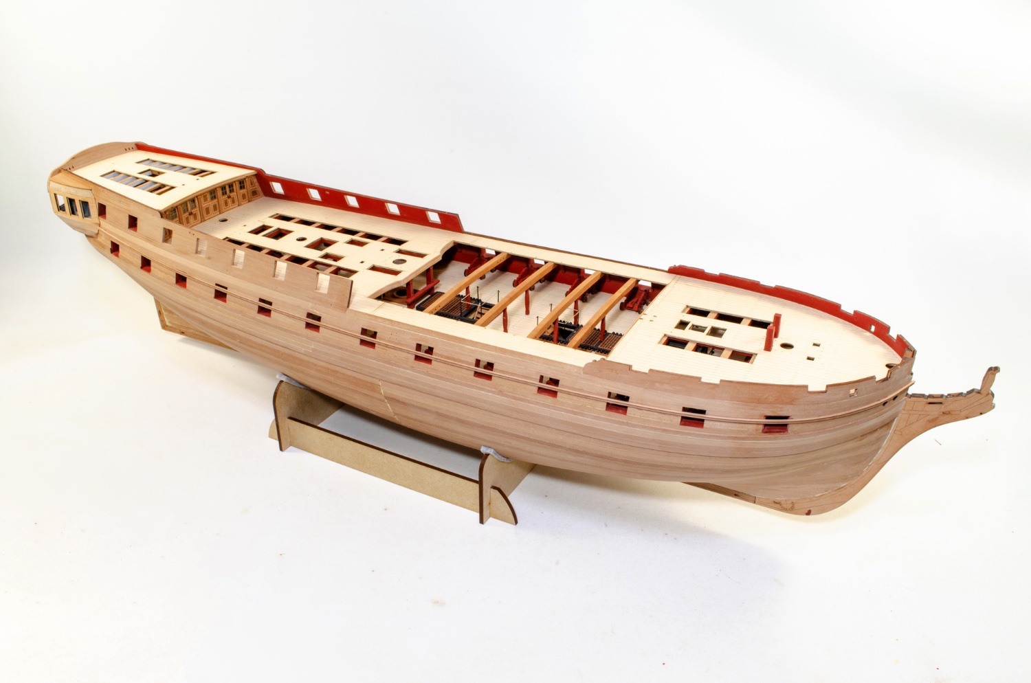
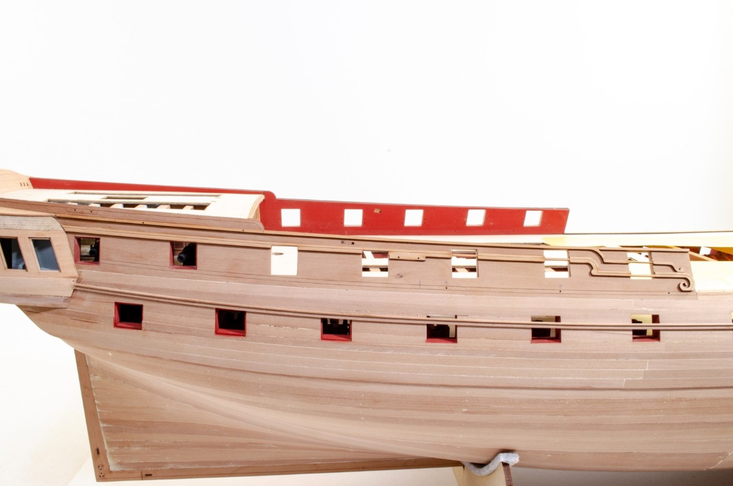
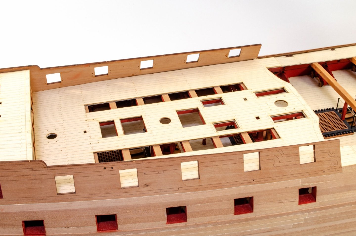
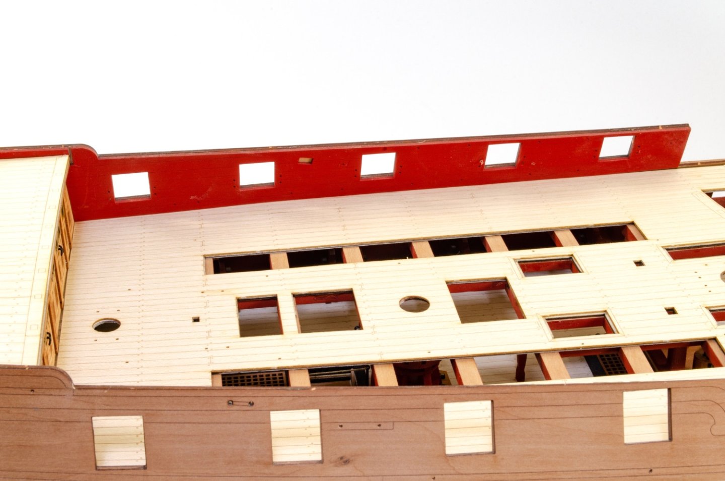
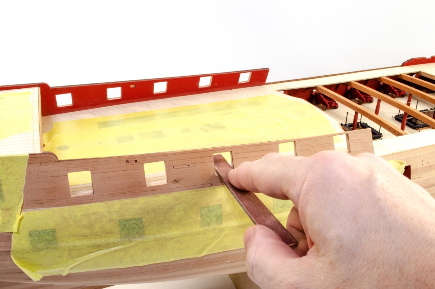
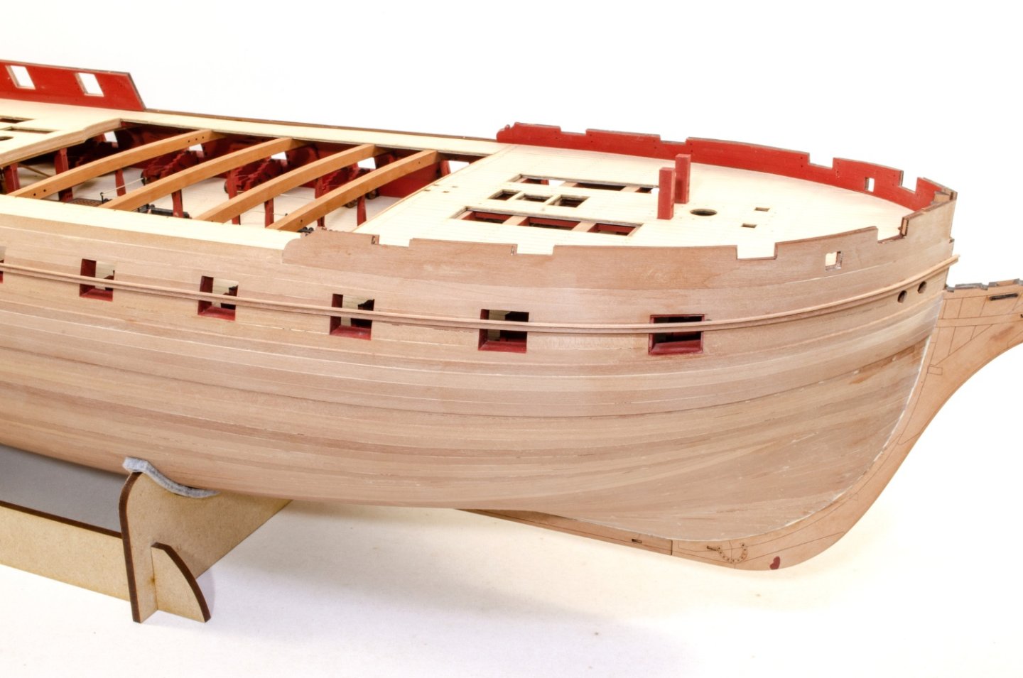
 ....continued. Now, those laser cut rails. These are now glued into the engraved positions on the outer bulwarks. Some extra parts are added to these to create a 3D relief. What we believe is the remainder of the original second wale from her 64-gun days, is now fitted. The position of this is crucial. Here you see the area around it masked off and the wale sanded. The timber which is obstructing the gun port is now carefully snipped away and sanded flush with the gun port edges. More gunwale position levelling, and the parts finally glued into place. The gun port positions on the forecastle gunwale are also prepared. Now it's the turn of adding rails to the stern of this beast. These are all laser cut and engraved. All you need to do is to make sure you fit them all in alignment. At this point, I glue in the second set of foremast bitts. And here is Indy so far. I have actually done more than this in preparing other assemblies, such as binnacle, ship's wheel, catheads etc. At this point, it's not long off adding some colour to this hull.
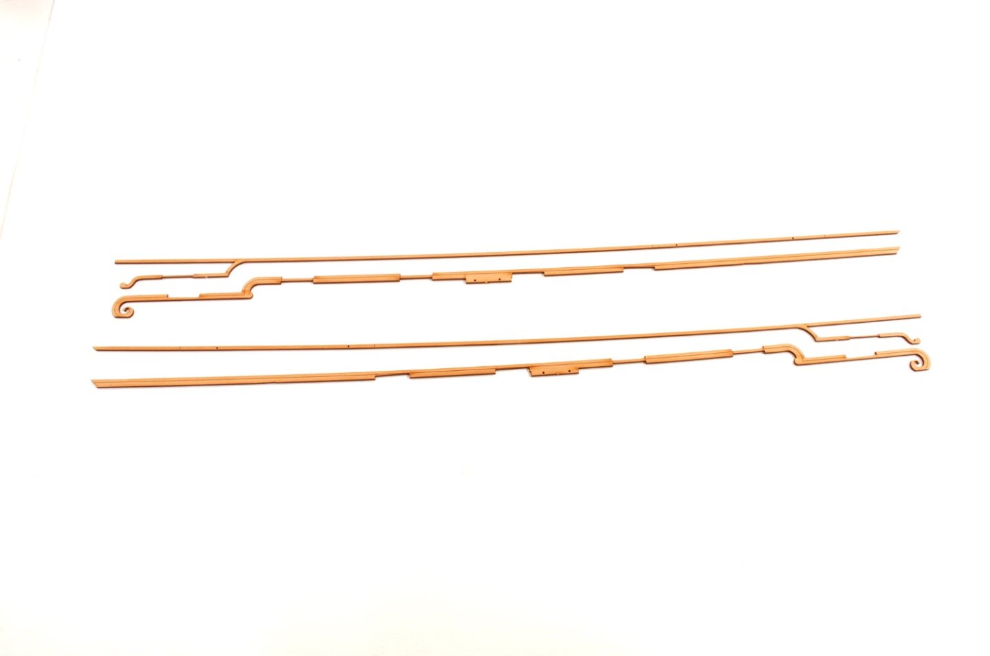


- 473 replies
-
- 47
-

-

-
- Indefatigable
- Vanguard Models
- (and 1 more)
-
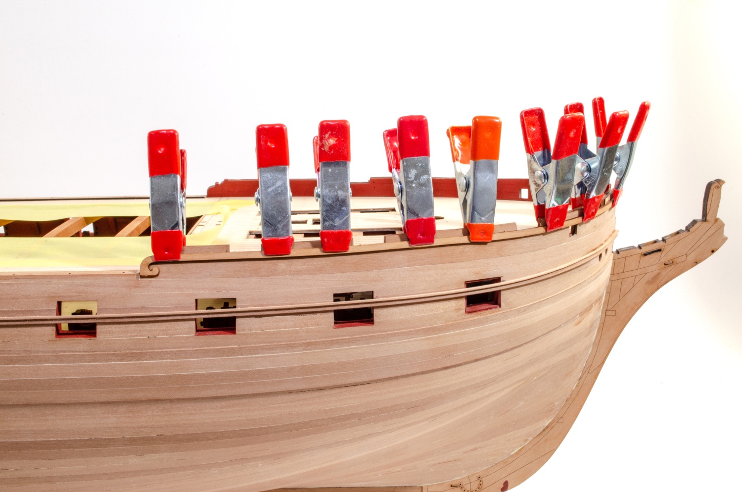
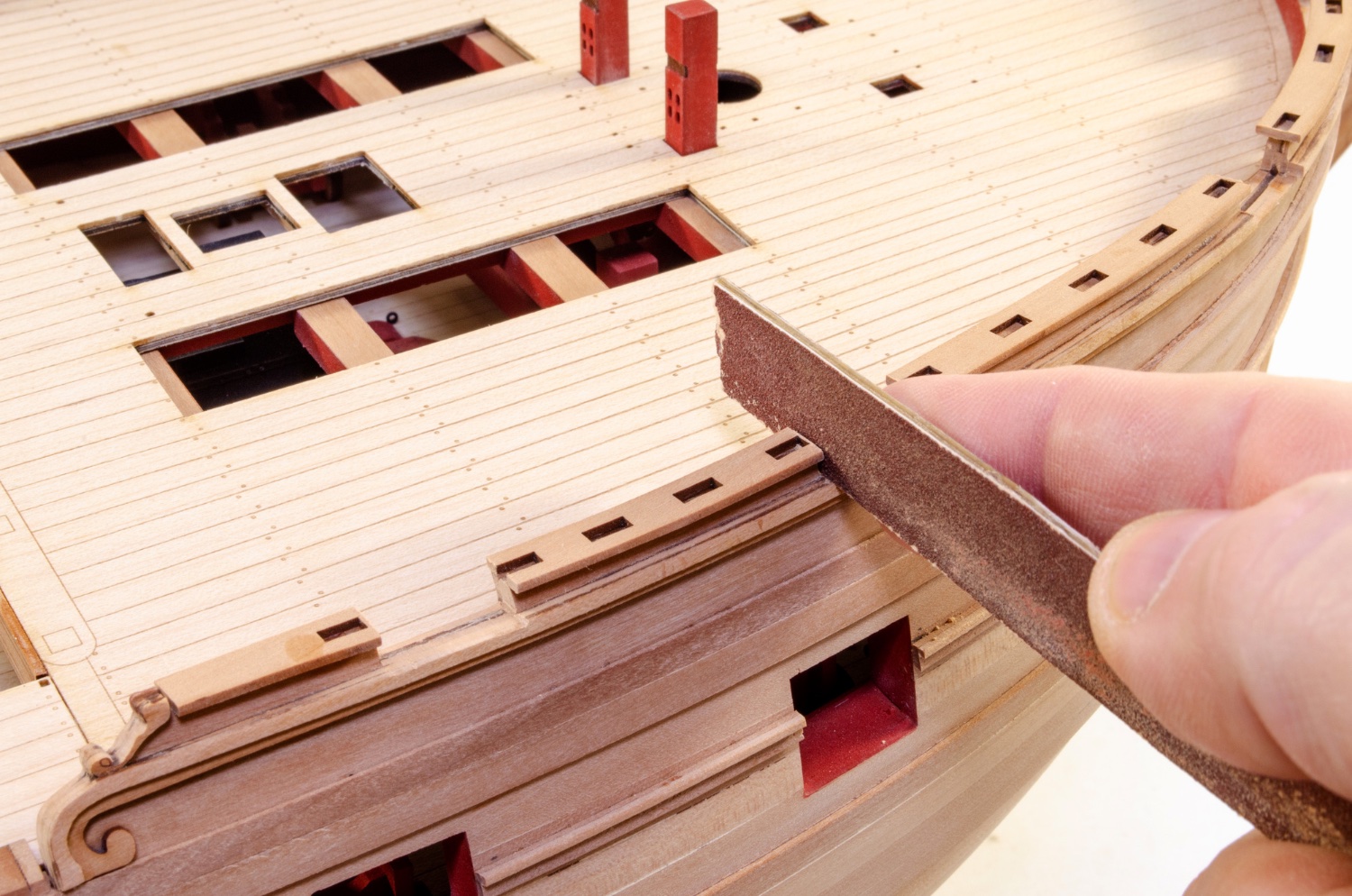
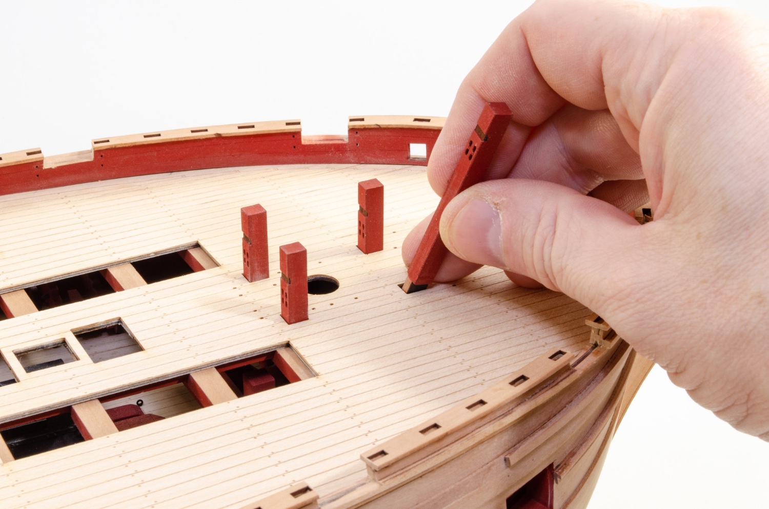
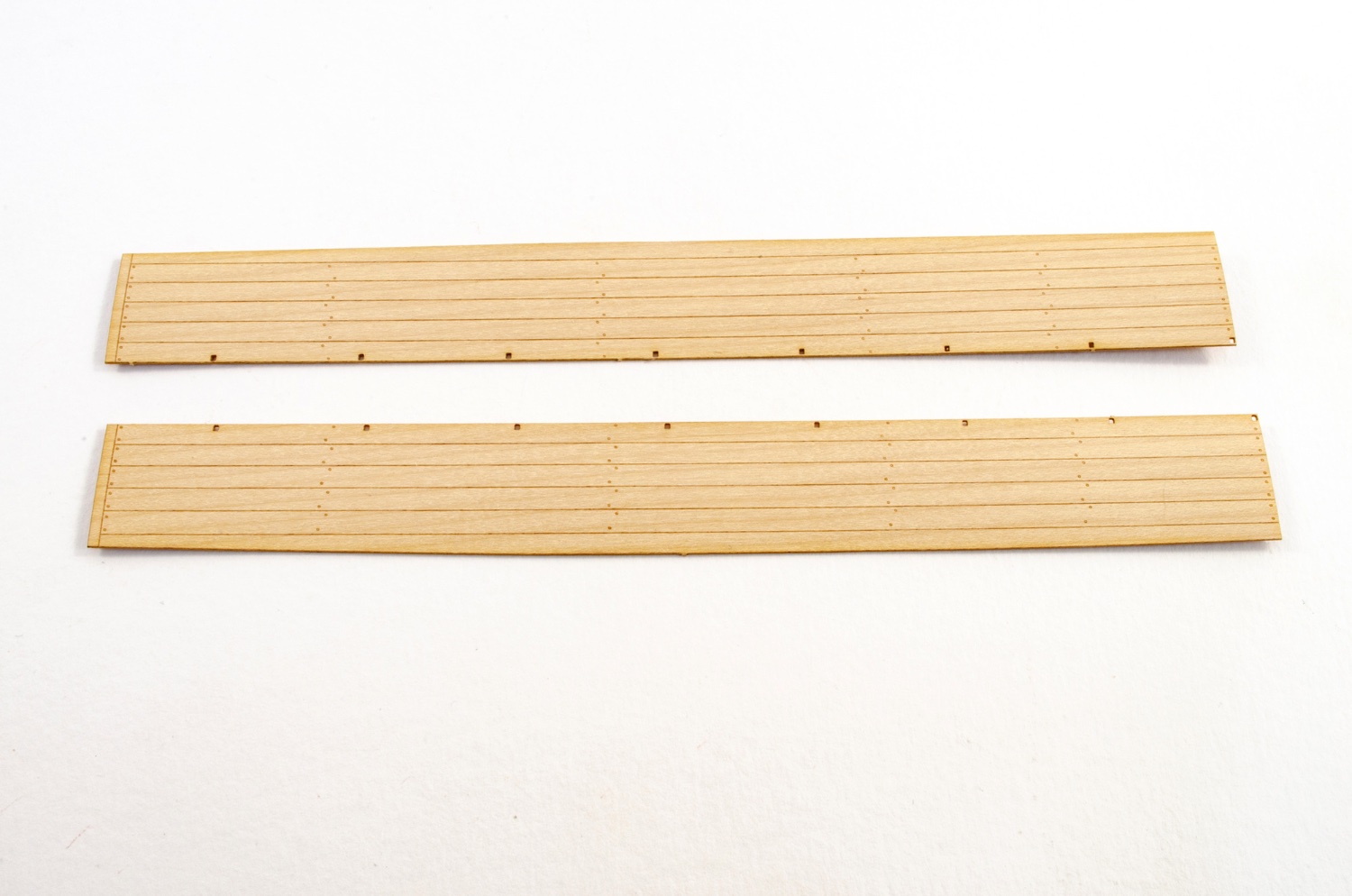
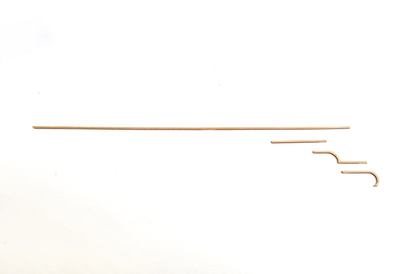
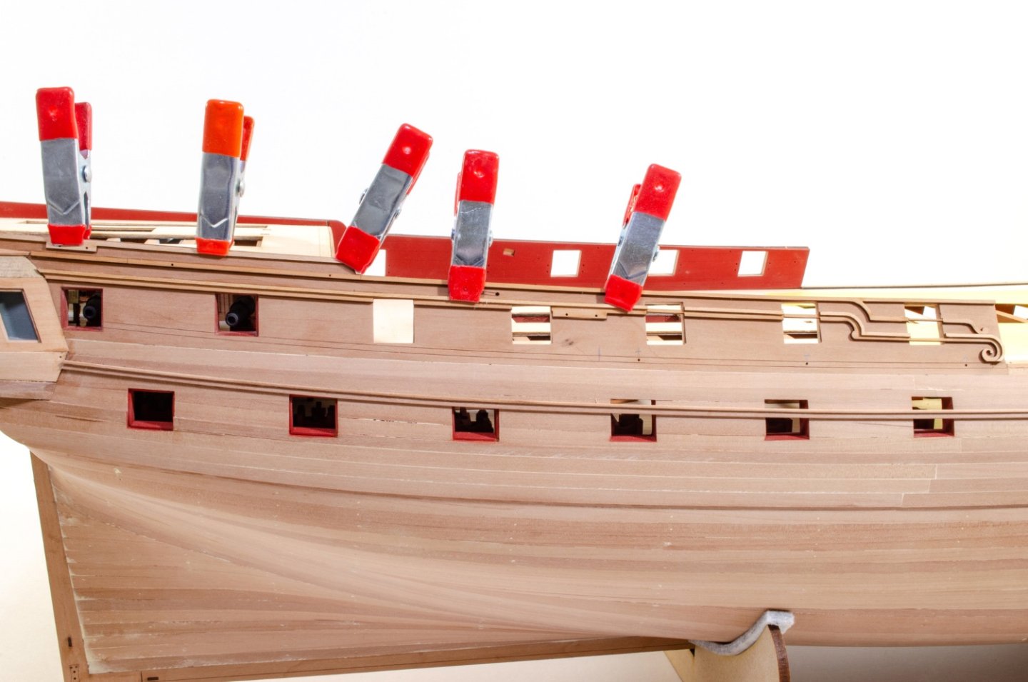
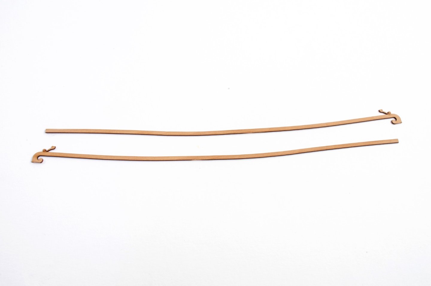
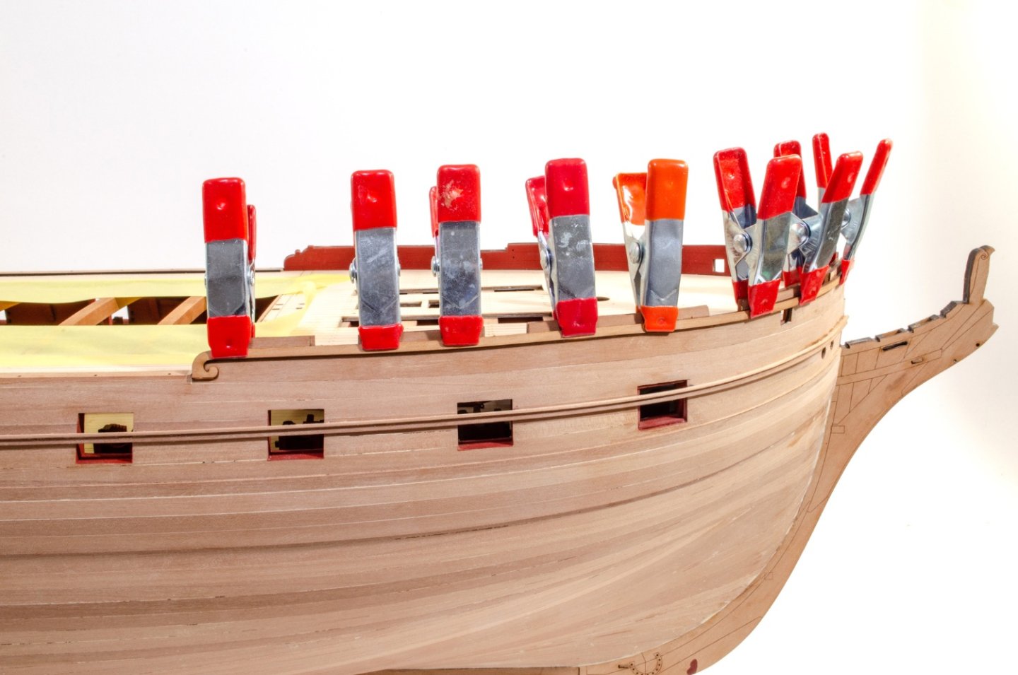
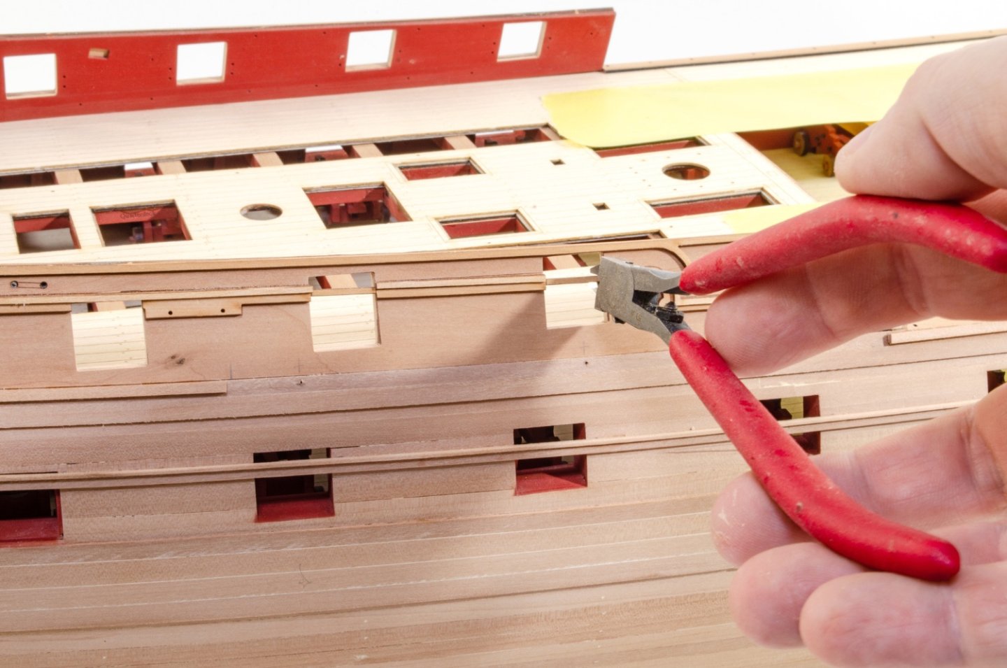
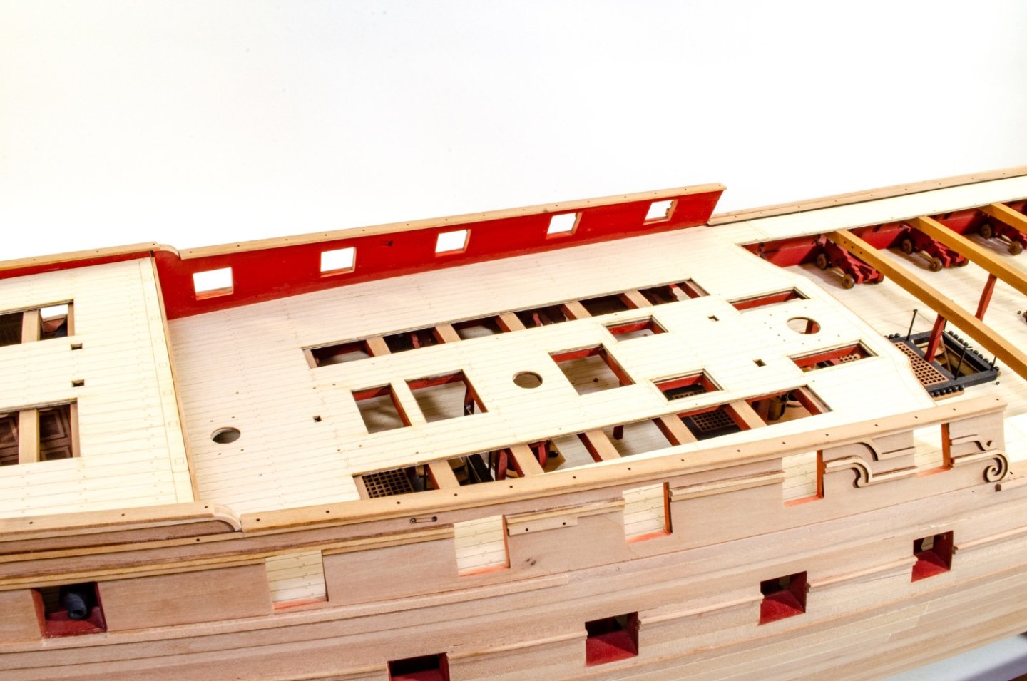
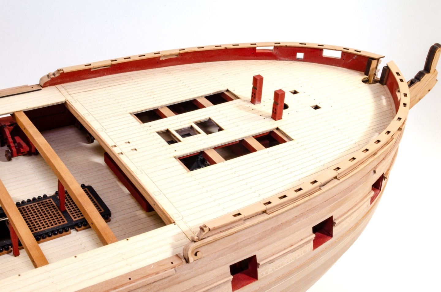
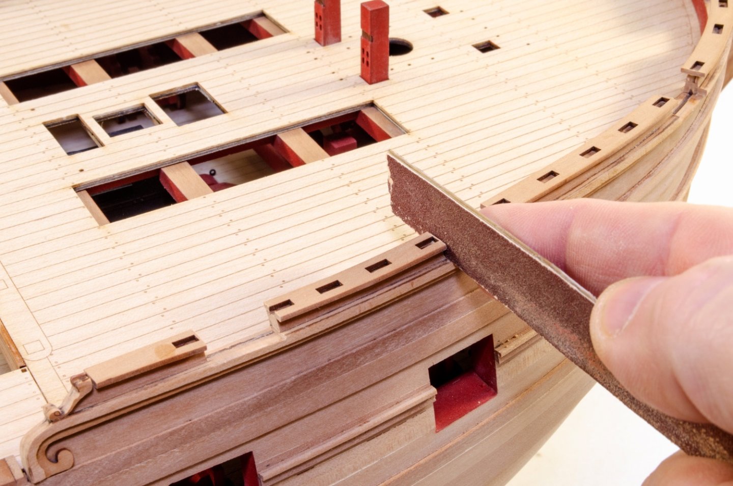
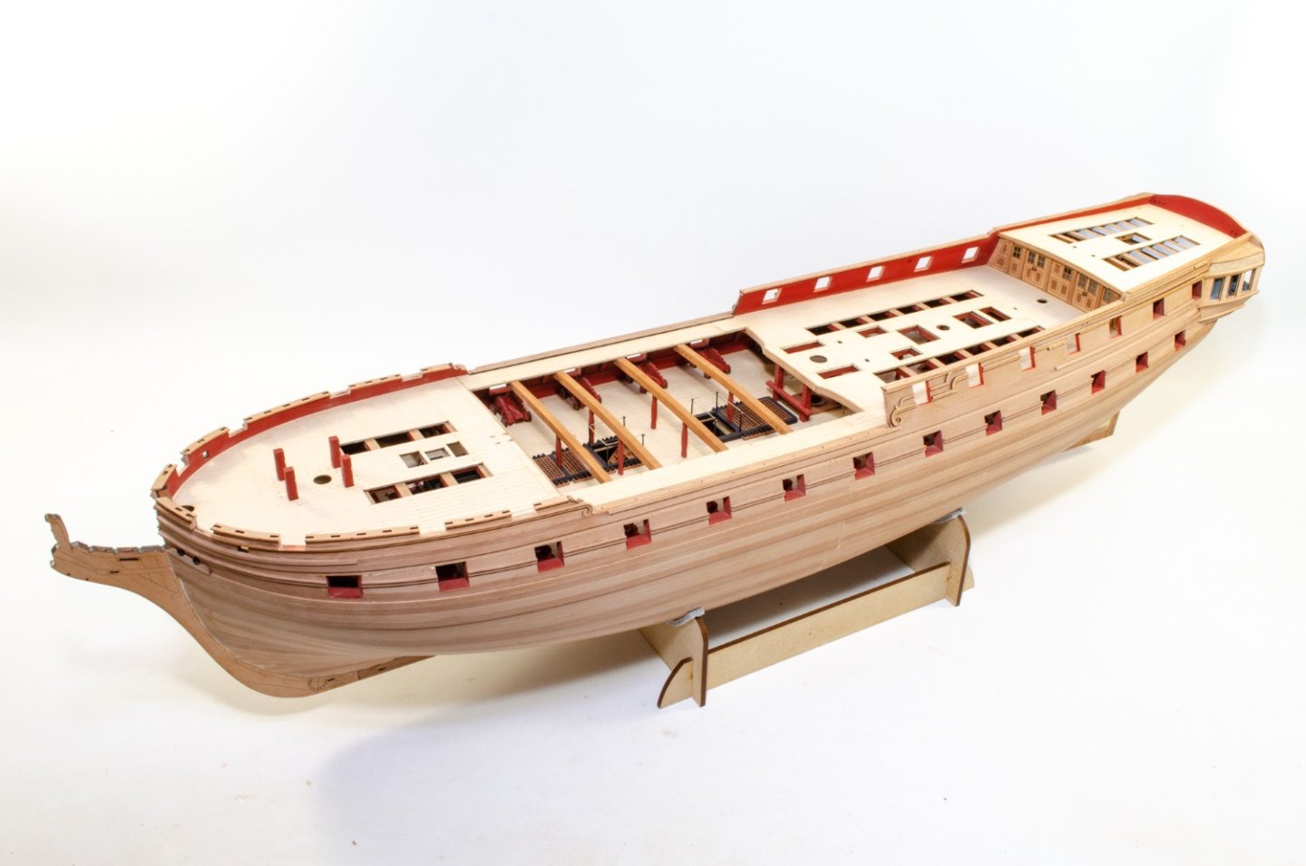
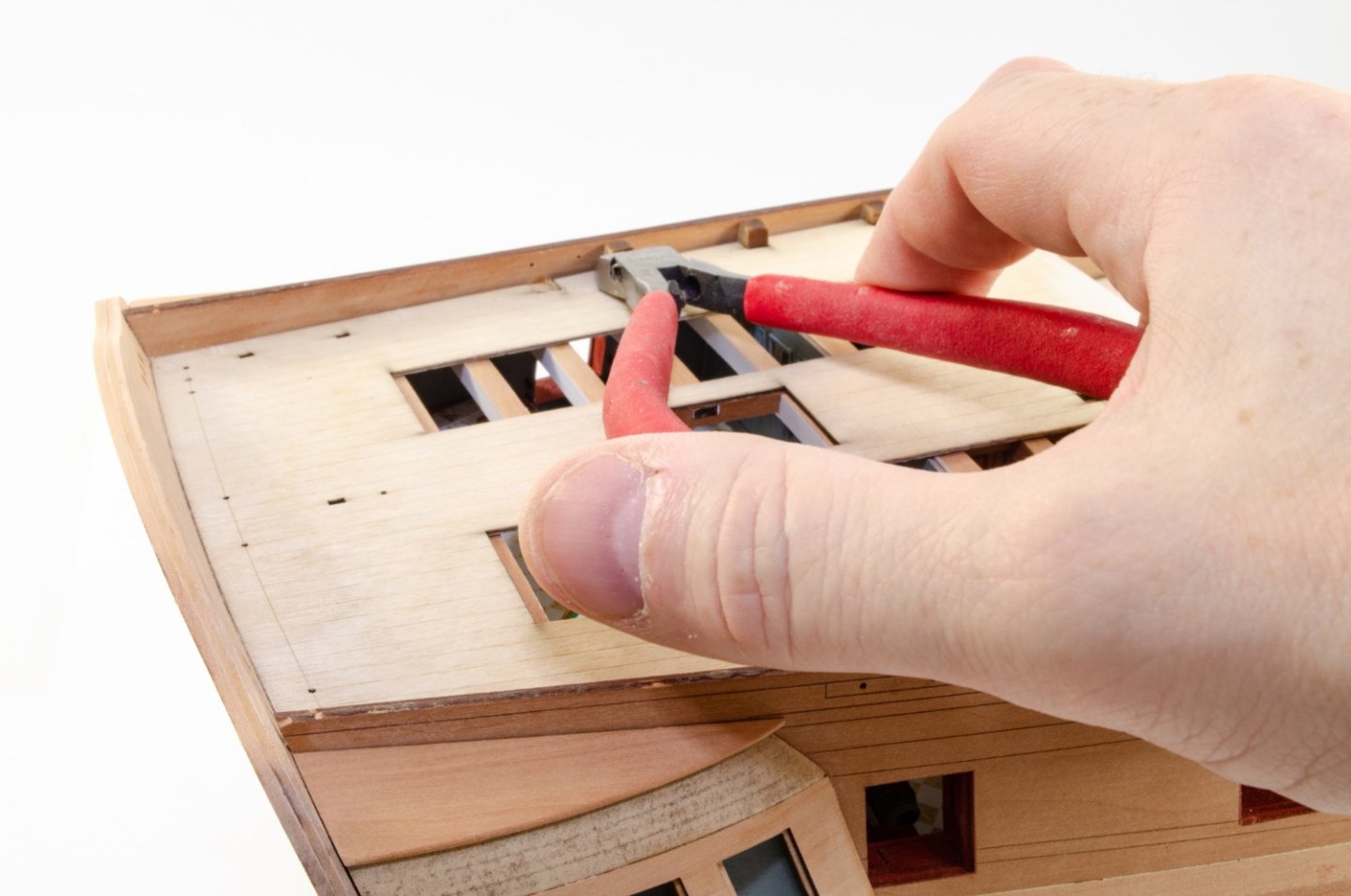
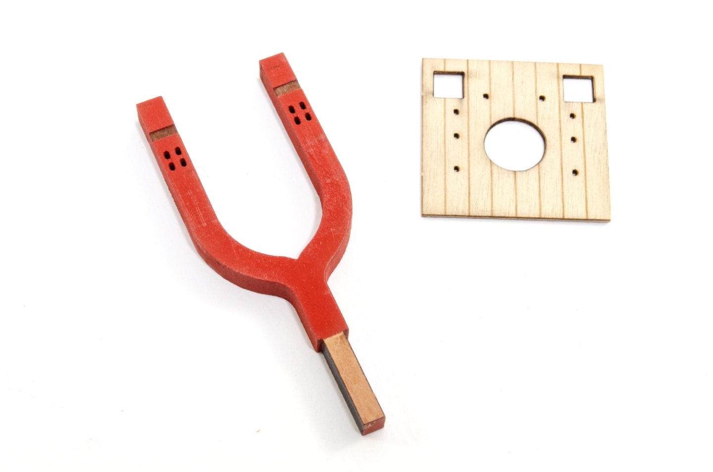
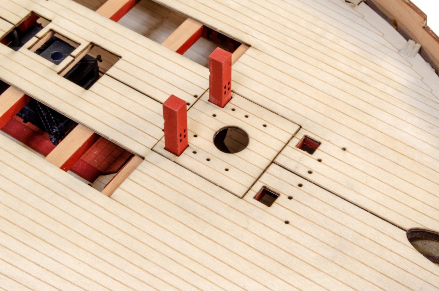
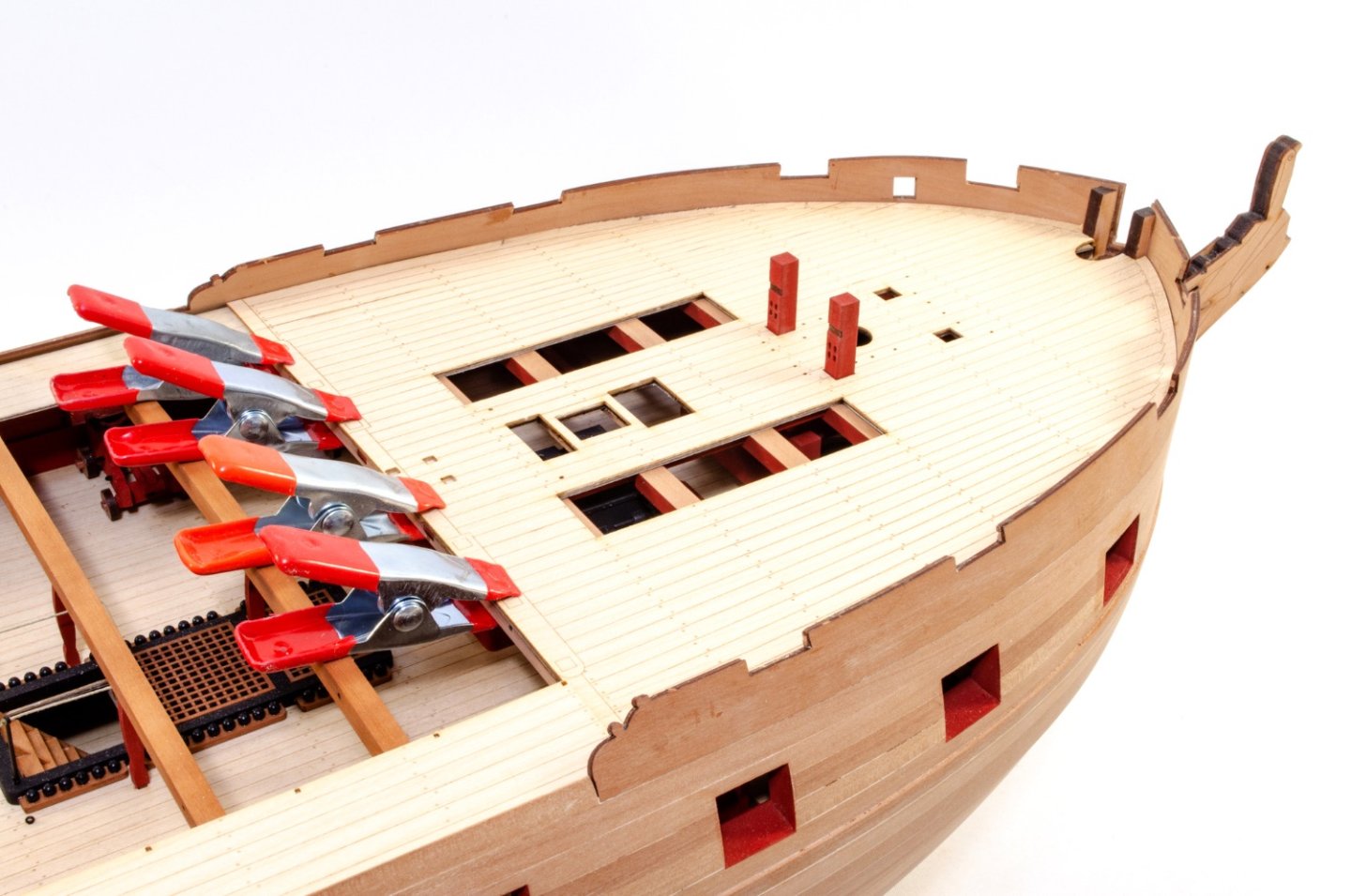
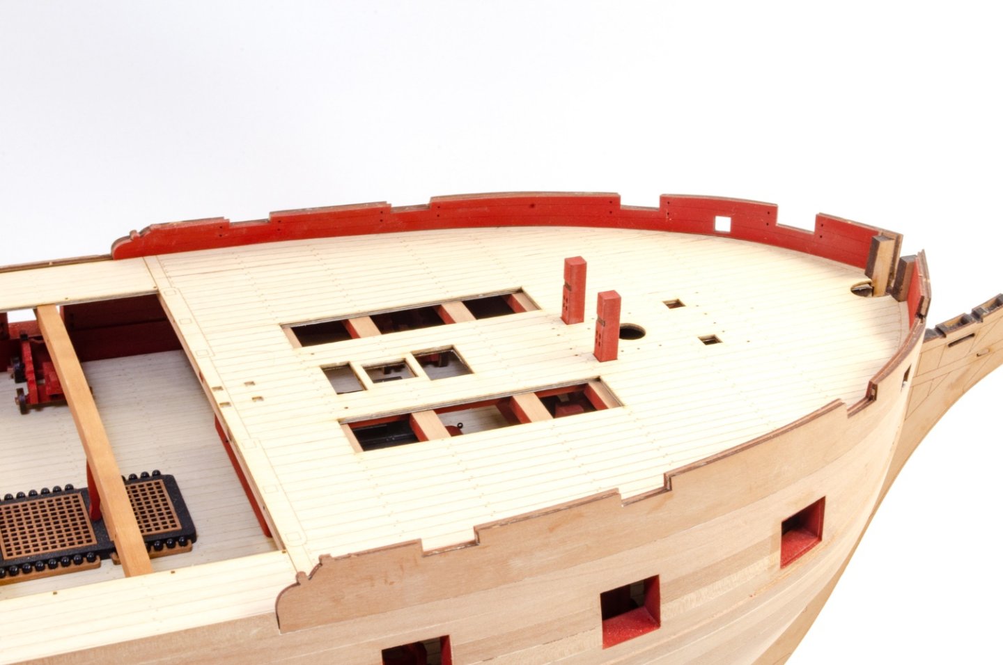
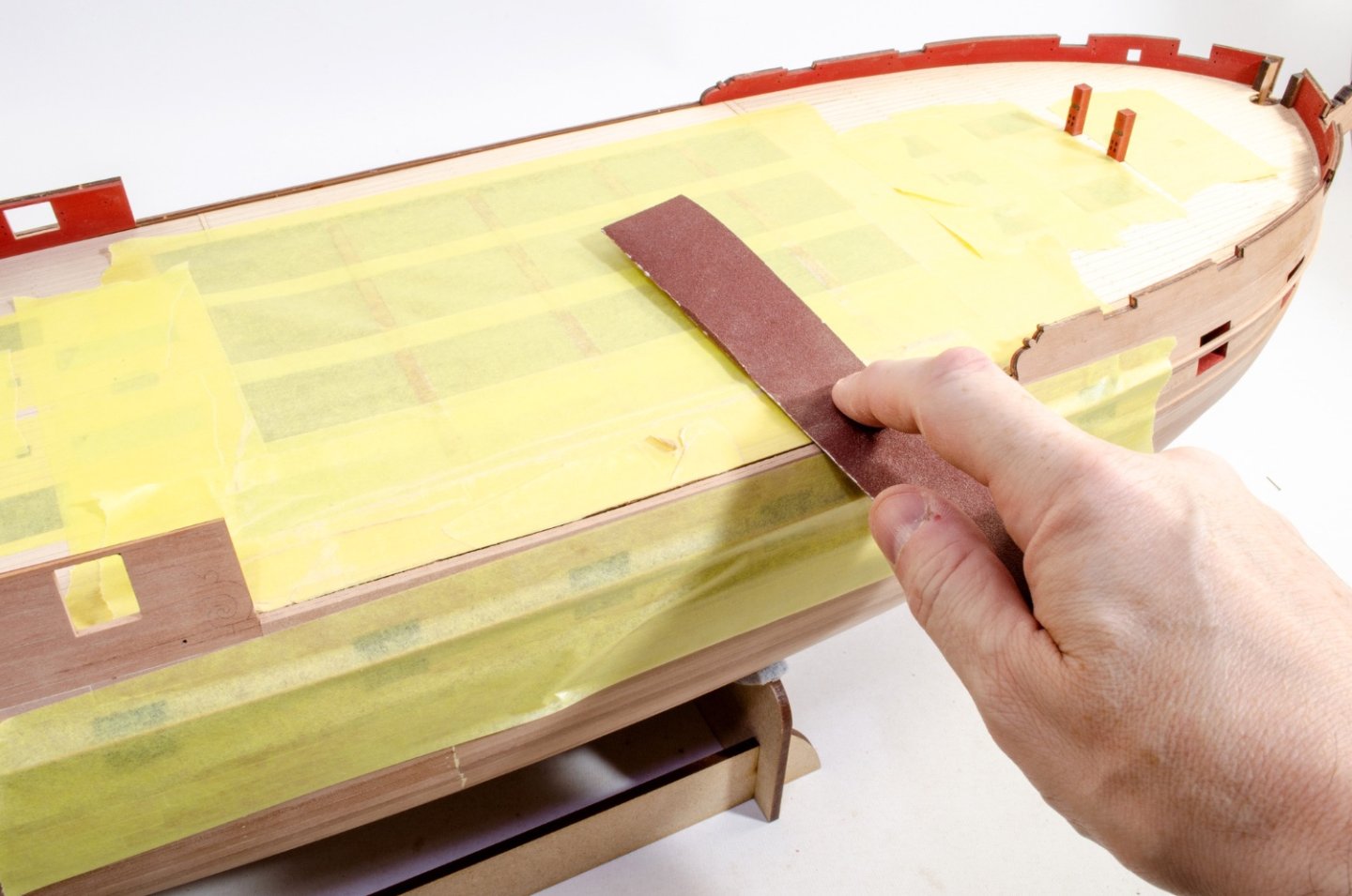
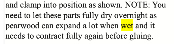
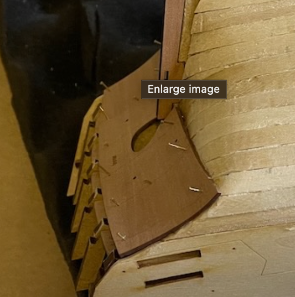
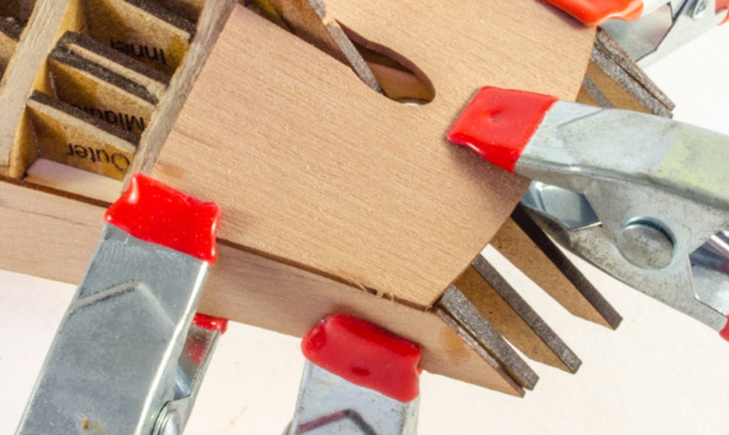
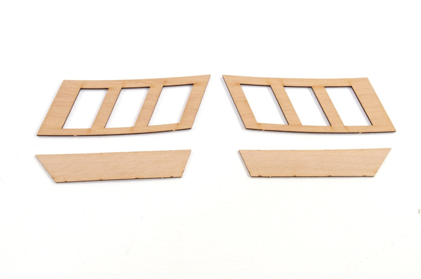
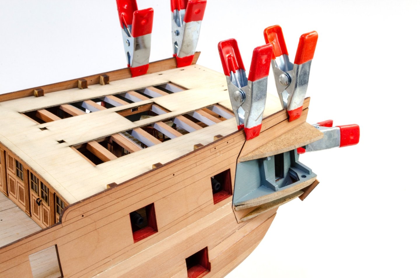
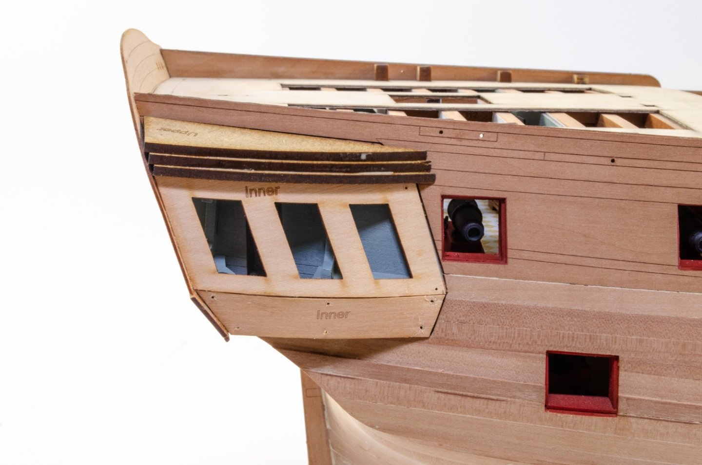
This update concerns fitting the inner bulwarks, finishing off the stern (for the moment) and fitting rails, gunwales etc. I alway find snipping and sanding away the last vestige of visible MDF from the model, to be very satisfying. This being the removal of the bulkhead ears above deck. Sandpaper is then used to properly level them. As this model is being fitted with the optional maple deck, test fitting and trimming that is the next task. Finally, this is carefully glued into place, checking alignment as I go. Plenty of 2-inch clamps are used to make sure the whole surface is in contact around the various openings. Before the forecastle maple deck can be added, I need to fit the foremast bitts. This is fitted at this stage to allow the lower ply sub deck to be fitted. This is now slotted through the deck beam frames and then the small deck section slotted and glues over it. With that in place, the maple deck can then be fitted. Deck test fitting is of course done before fitting the bitts. Lastly, the gangway maple deck section are glued into position. With the deck sections fitted, the inner bulwarks are painted in red and fitted. The forecastle ones were first soaked and clamped to shape before working with them. More gun port tidy up now, using the same homemade sanders I used for the main gun deck. At this point, I needed to fit some of the external details, such as rails etc. These are a combination of strip timber and pre-cut parts. Firstly, a 1mm² strip is glued to the edge of a 3mm² strip, left to dray and the edges subtly rounded. The rail is then fitted at a position equidistant from the wale below it. A 12-inch steel rule is now wrapped in sandpaper and used to level the gunwale positions for later.


- 473 replies
-
- 34
-
-
-
- Indefatigable
- Vanguard Models
- (and 1 more)
-
I did try 🤣 (from the Sphinx manual)


-
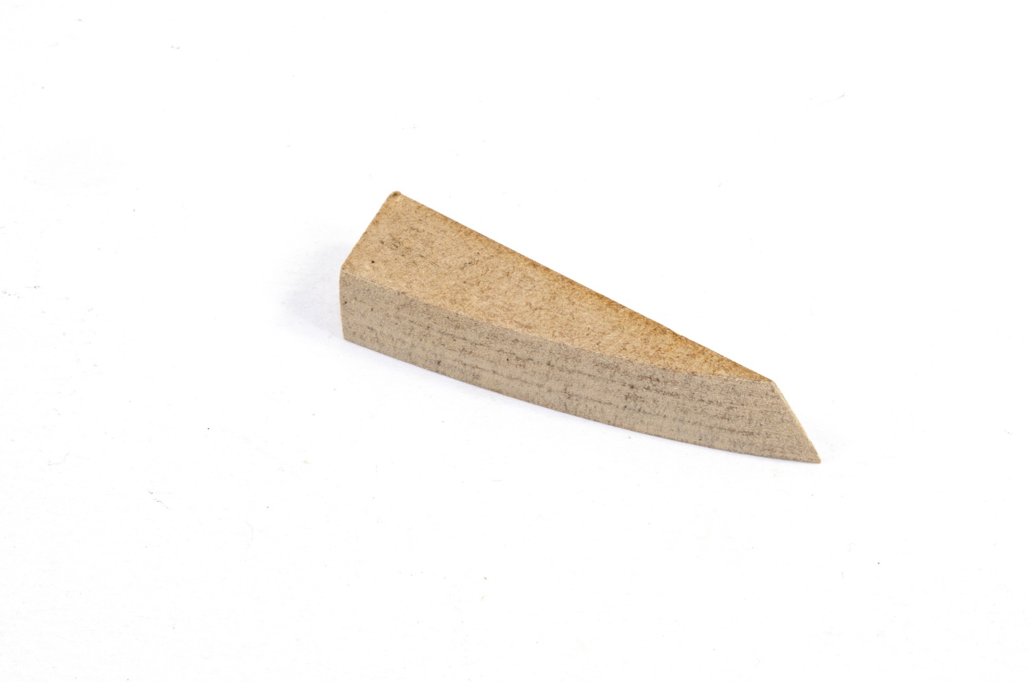
I think we recommend that the pear should be allowed 12-24hrs to throughly dry. I know I've still had the stuff swollen by a few mm even after almost a full day's bench session. It's like the final welling only goes back in last hours 🤪
-
Ah, and if that piece is still damp, it won't have shrunken back to its proper size. Pear swells a LOT, so you need to make sure it's bone dry.
-
If you temporarily sit the the upper counter and stern fascia in place, and the fascia sits about 2mm above the bulwark level, then you'll be perfectly ok.
-
Looking at the counter, I think you placed it lower, not higher, than mine. Higher is closer to top of stern, not higher when upside down. Take a look where mine falls in relation to the rudder post, and then elevate yours about 2.5mm closer to top of hull than that.

-
Just add a little piece to infill there. It won't be seen.
- 106 replies
-
- 1
-

-
- Erycina
- Plymouth Trawler
- (and 3 more)
-
I can confirm that my tests with these show they can be thinned with regular tap water and also brush-painted. I'm really picky about paints as I've trialled and used lots of garbage whilst working for magazines, but these are superb. Very nice indeed.
-
Ok, this topic has been pruned of around 30 posts that were asking status, and those trying to explain things. When I have news on this project, then here is where I'll post it. If there is no post, then I have no news, so please don't keep enquiring.
-
This has been such a wonderful project to follow and nice seeing the little things you've done throughout to change her too. As for lodging and hanging knees, I had real pleasure fitting those on Indy 🤪 I help we'll eventually see you try your hand at the new super frigate.
- 858 replies
-
- 5
-
-
-
- Sphinx
- Vanguard Models
- (and 1 more)
-
Hi Glenn, Those sides needed fairing in far more before you added the bulwarks. Sanding needs to be done to fair the MDF into the deck edge at the rear, and that will also bevel those stern timbers, possibly by half. Take a look at my pics. Also, that lower counter needed sanding into the hull. Check out the subsequent pics in manual. You need to ensure the lines of the hull flow and you have maximum bulwark contact to the timbers.

- 106 replies
-
- 3
-
-
-
- Erycina
- Plymouth Trawler
- (and 3 more)
-
Nice to see her progressing so well. The broken ear you had on bulkhead 13: there was a temporary blank panel in the bulkhead which protected those ears, and the panel was designed to be removed after those gun port strips were fitted, and that bulkhead had some strength. Nice work on the BE mods too.
-
That is lovely work and a nice, clean edge too.
-
Just incredible. It makes me want to give up and play video games full time! 💯 The time spent is clearly seen in every detail.
- 1,784 replies
-
- 9
-
-

-
- winchelsea
- Syren Ship Model Company
- (and 1 more)
-
I would always advise priming/painting 3D parts as the resin does probably have a few microns (at least) of translucency to a normal depth. Where the part is thin, you'll easily see daylight through it.
-
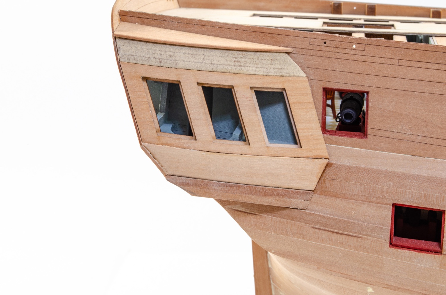
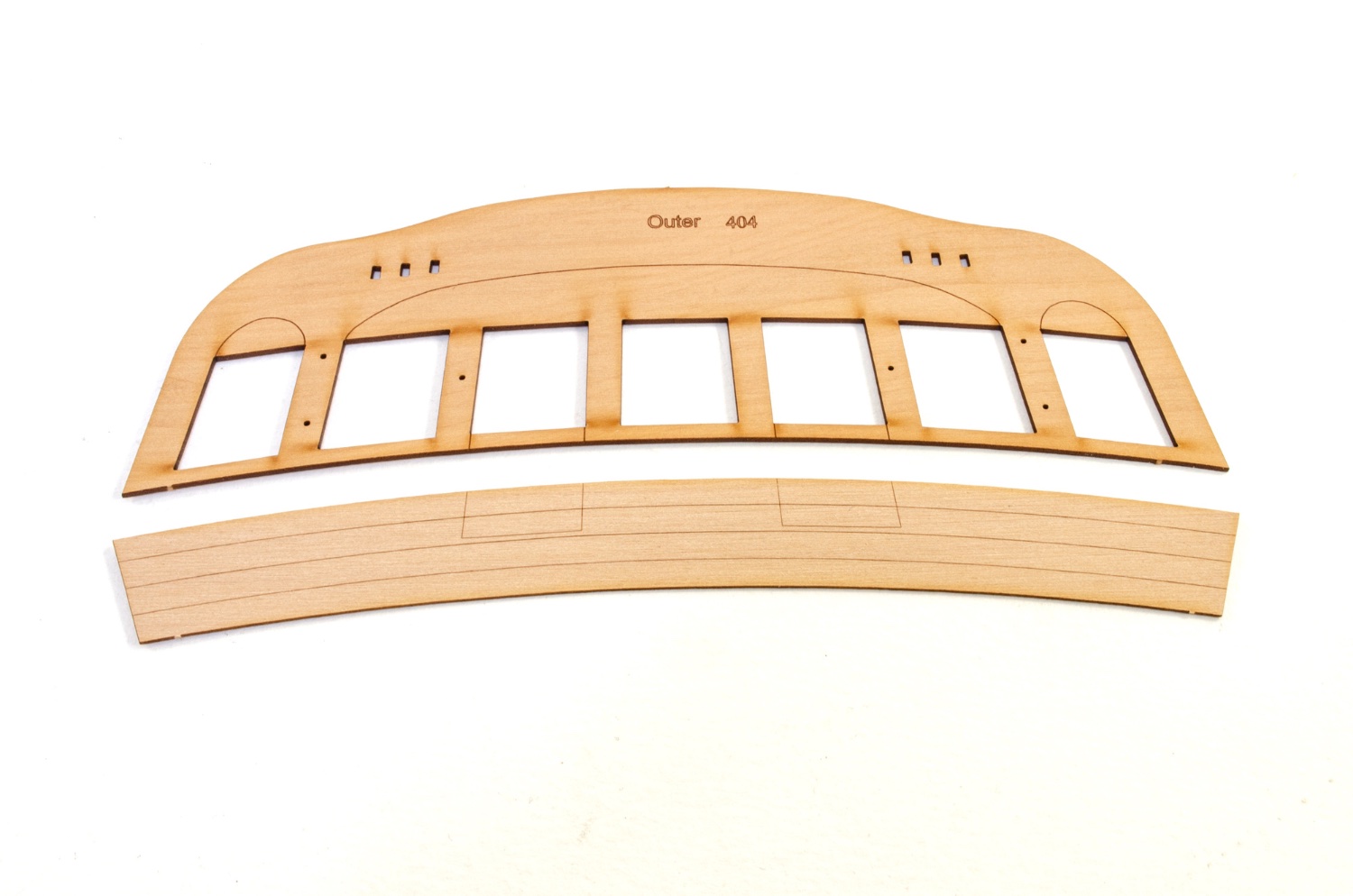
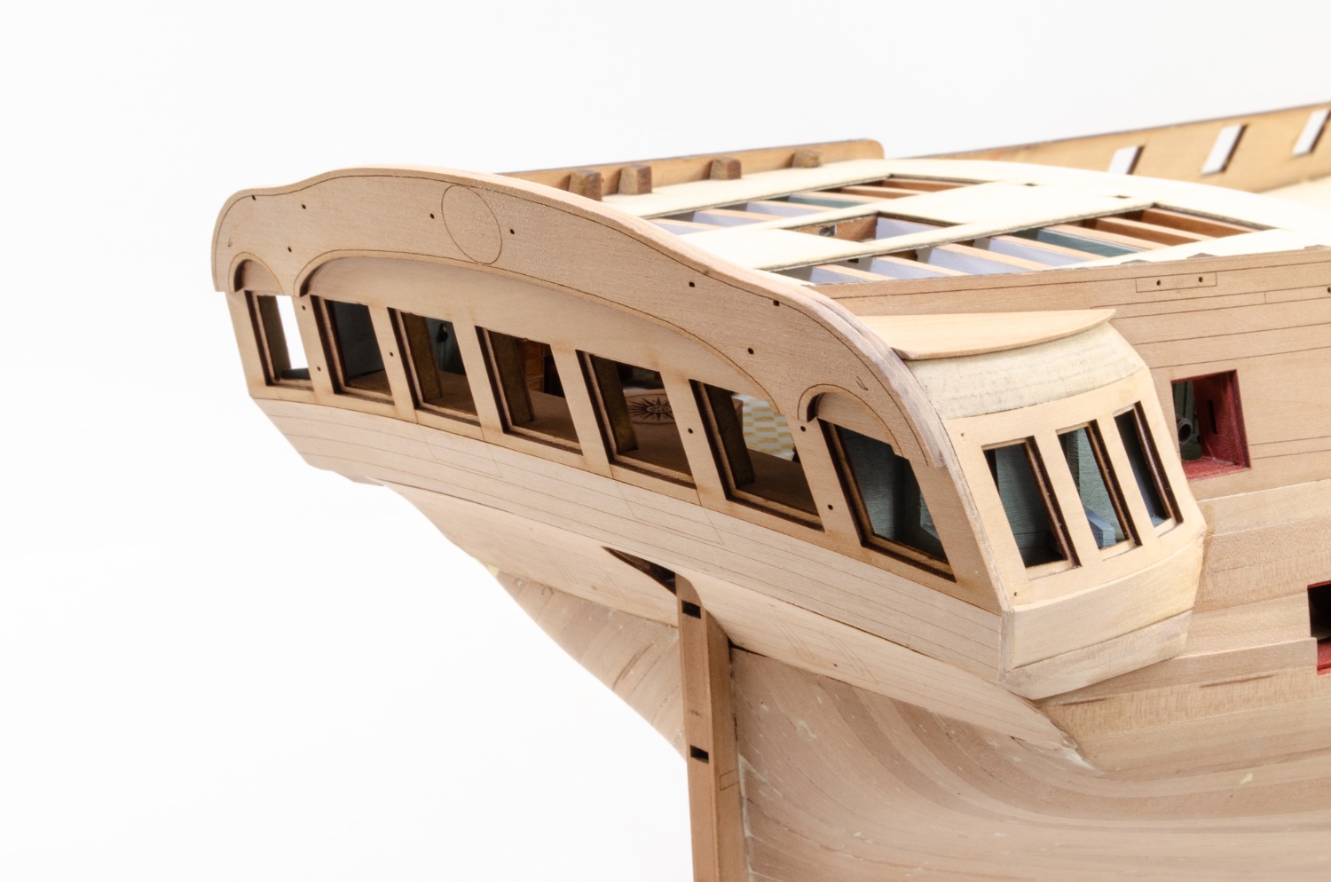
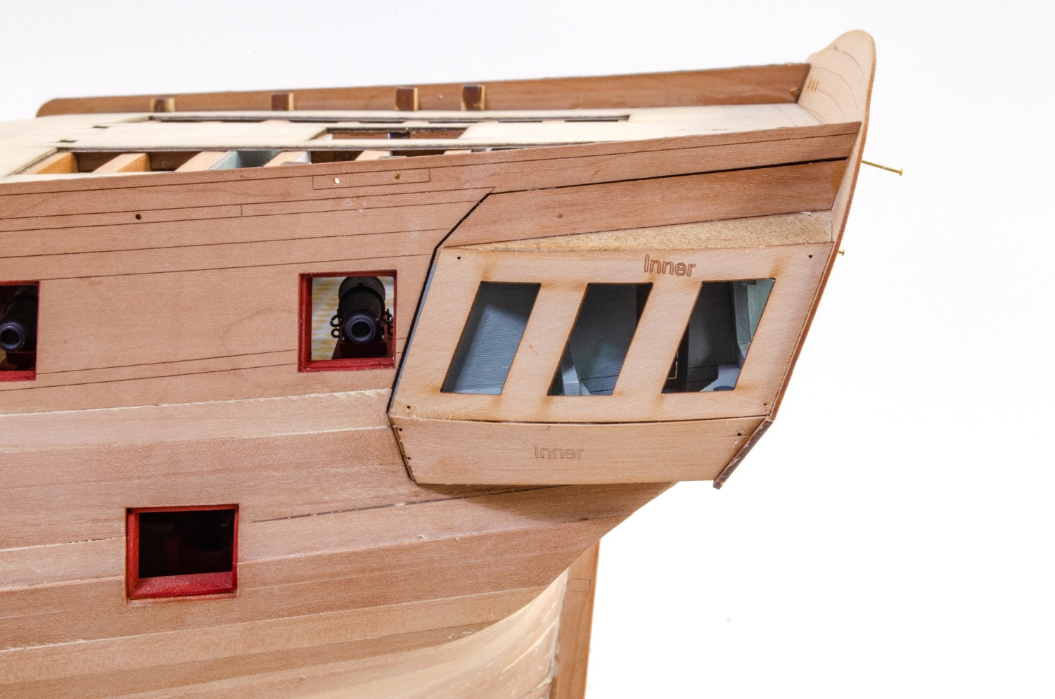
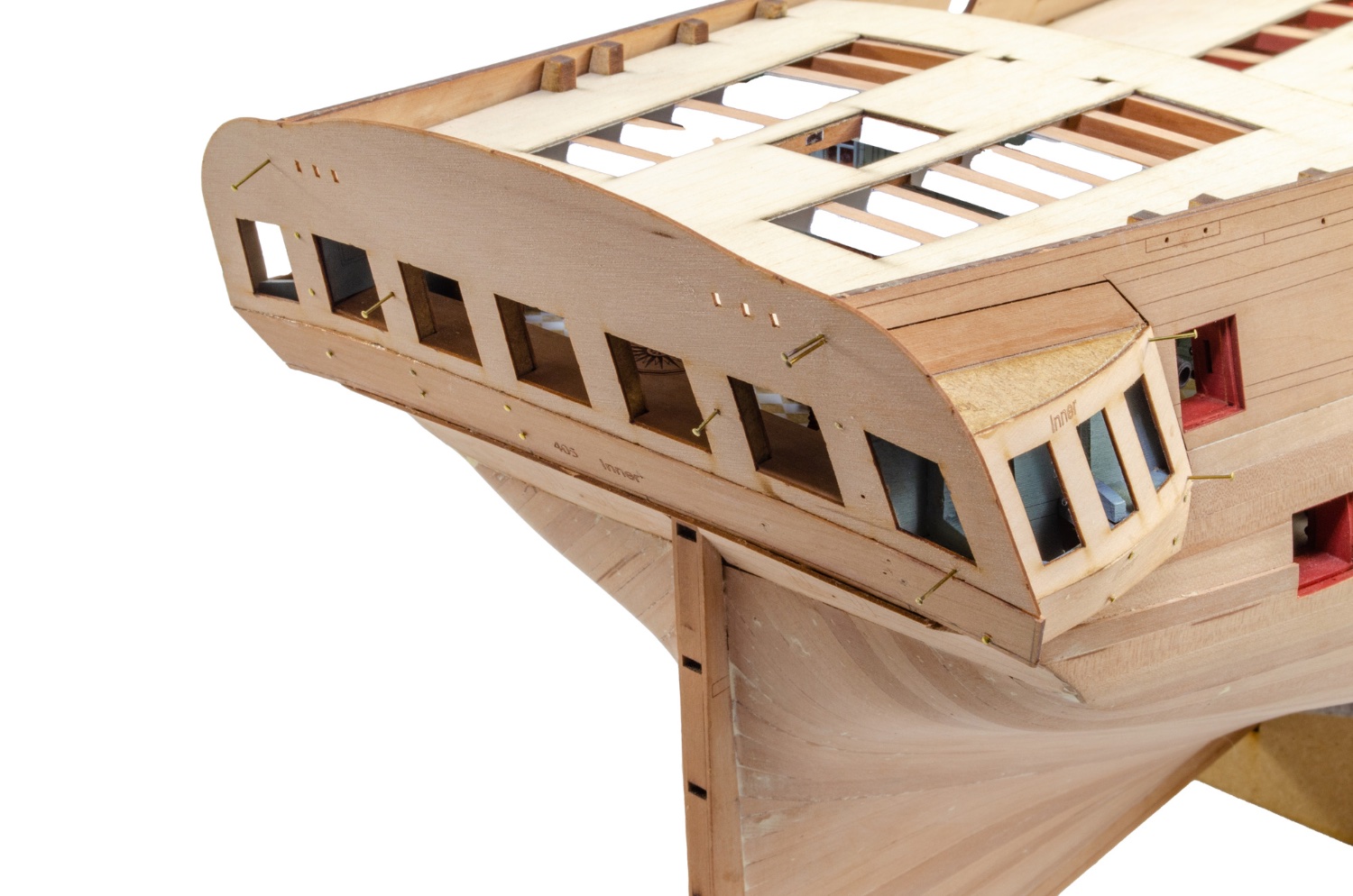
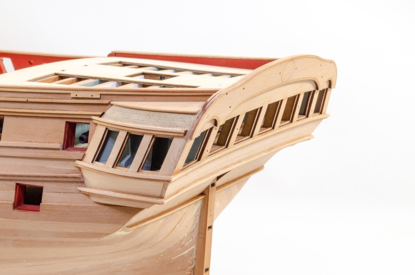
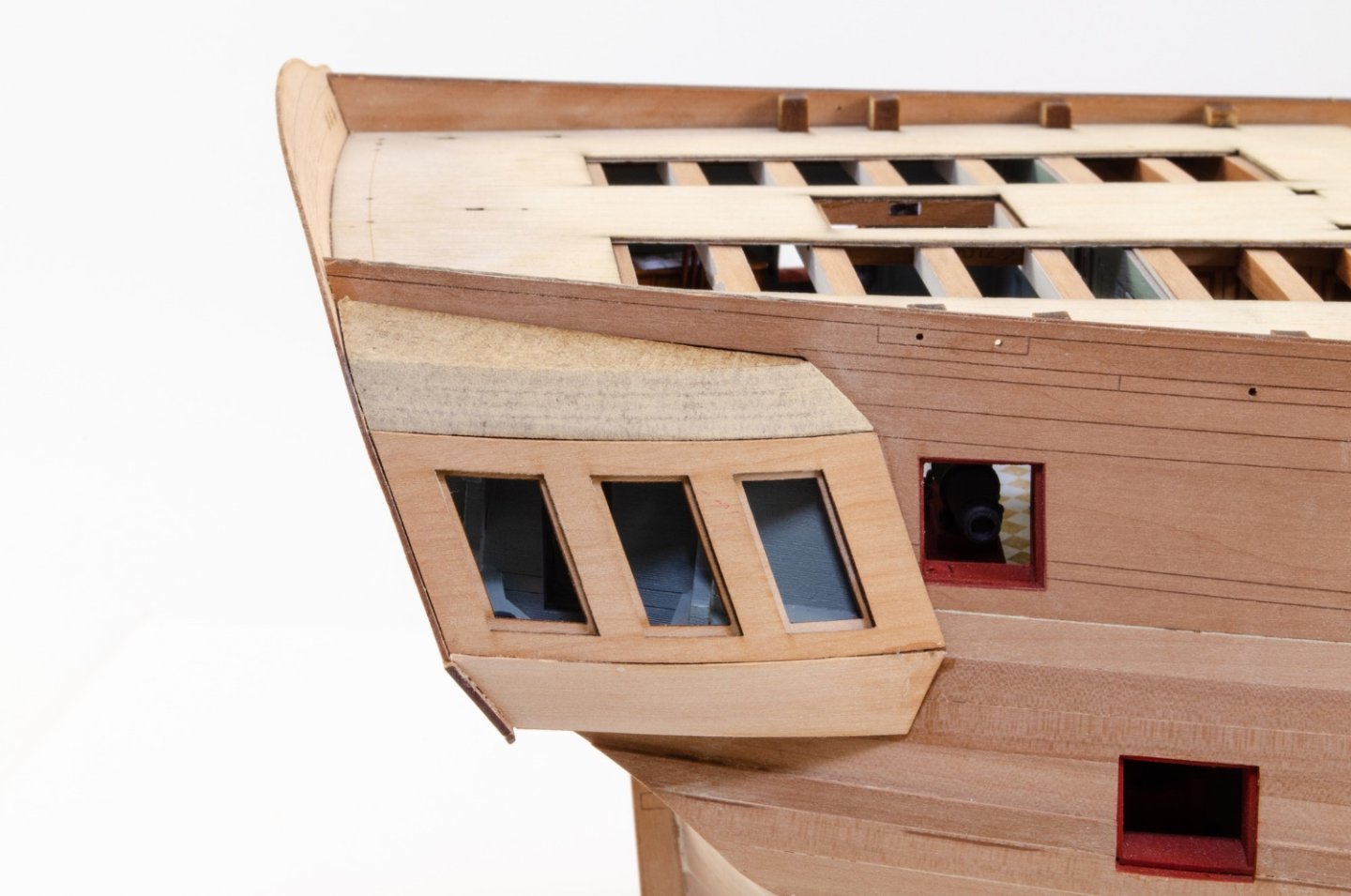
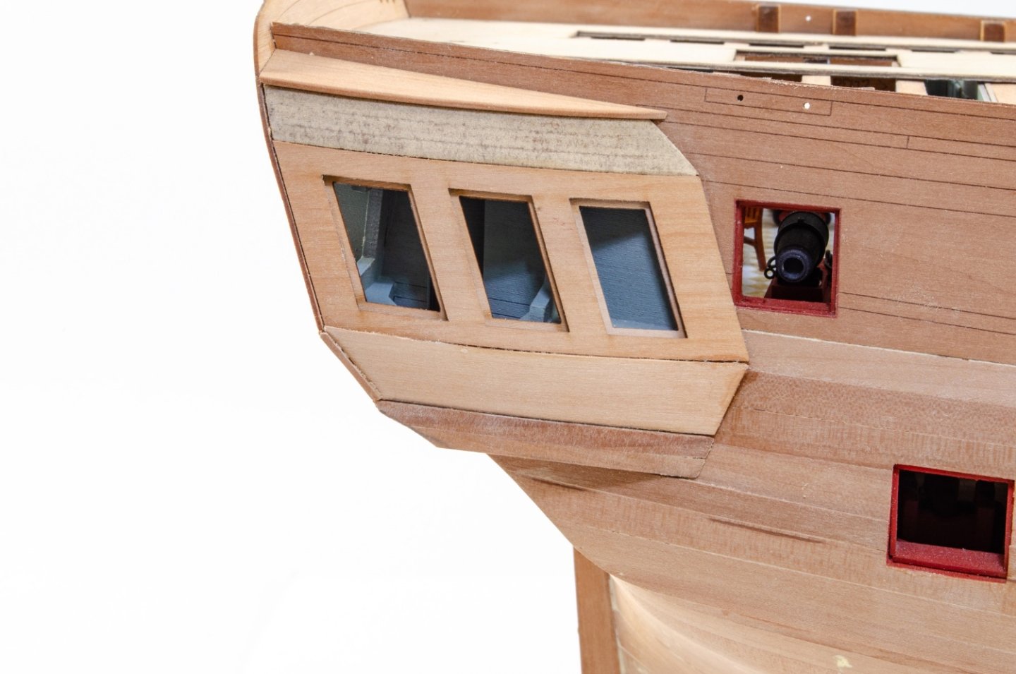
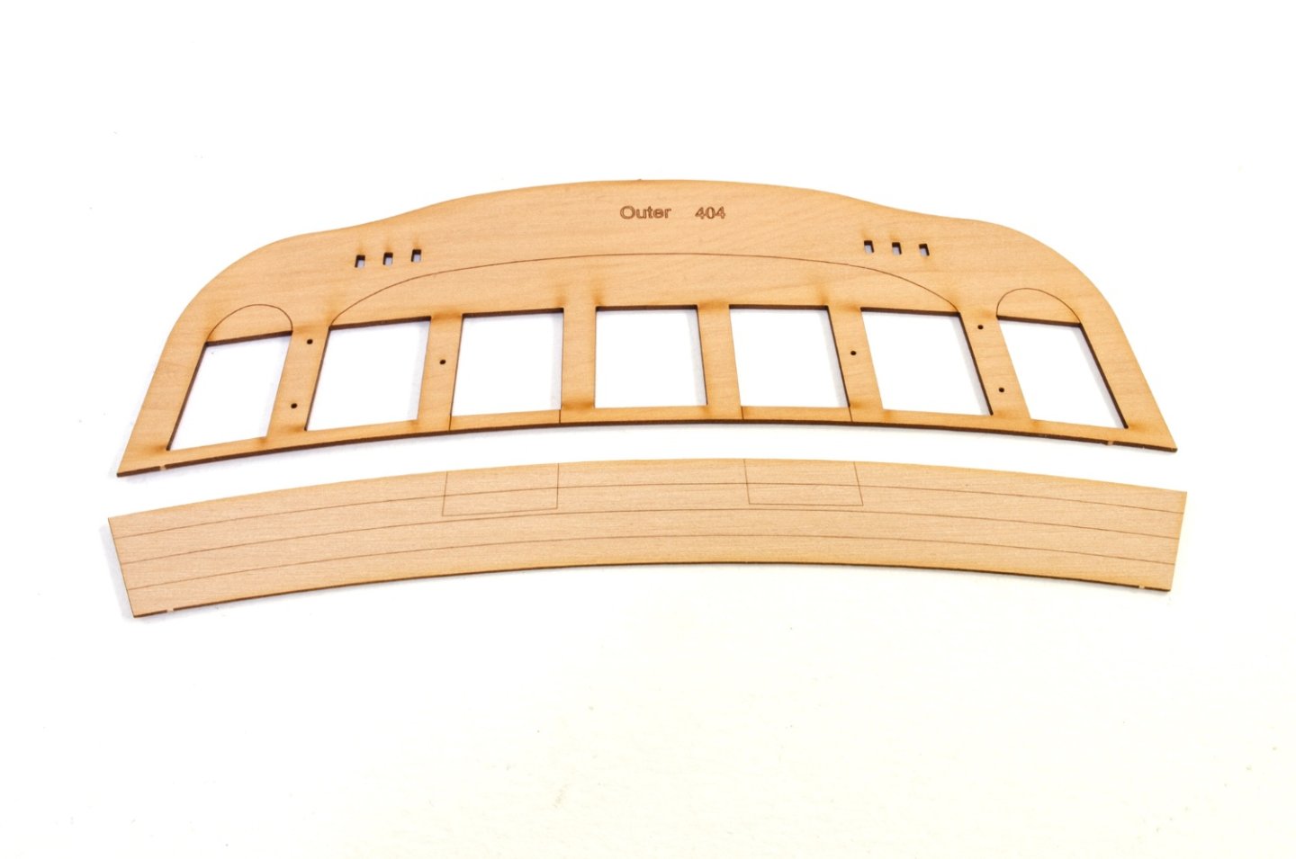
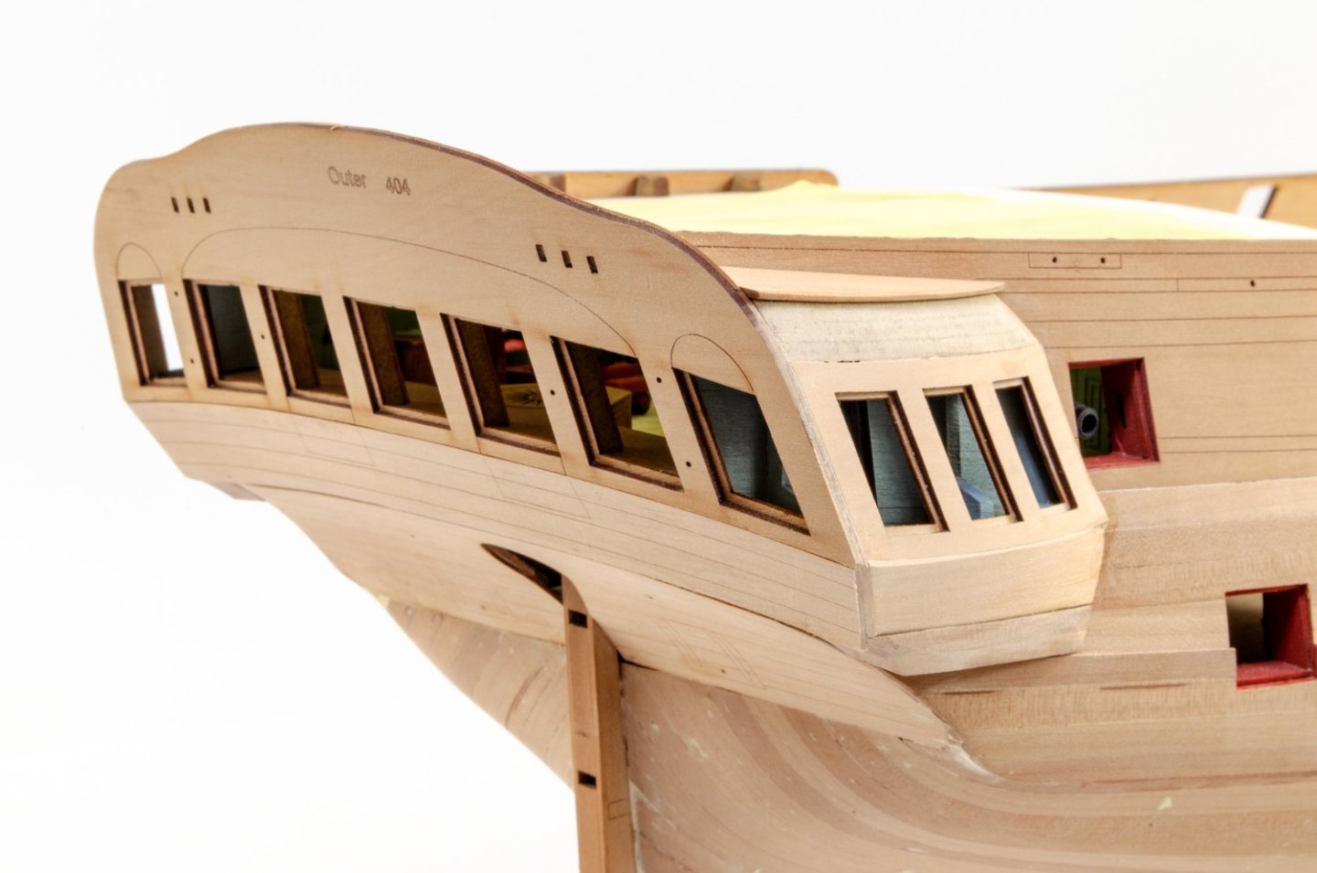
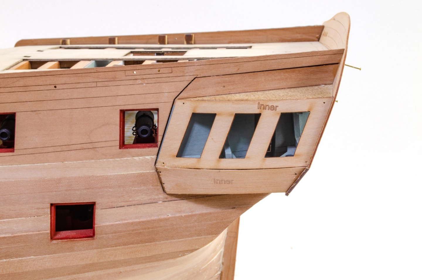
Before I glue the roof into place, it needs to be tested against the gallery once the outer skins are added. WIth those glued into place, the roof is finally trimmed to size and also glued to the model. On top of that is the pear cap which will slightly overlap the shingles that will later be fitted. The pear parts that make the lower galleries are now shaped and fitted. Time to fit the outer stern panel and quarters. I highly recommend you use CA for this so there's no curling of the parts. These are then shaped and the gallery/stern area given a finishing sanding to even up all edges etc. And lastly, the engraved upper stern is fitted and then also sanded into the rest of the hull. More next time...

- 473 replies
-
- 51
-
-
-
- Indefatigable
- Vanguard Models
- (and 1 more)
-
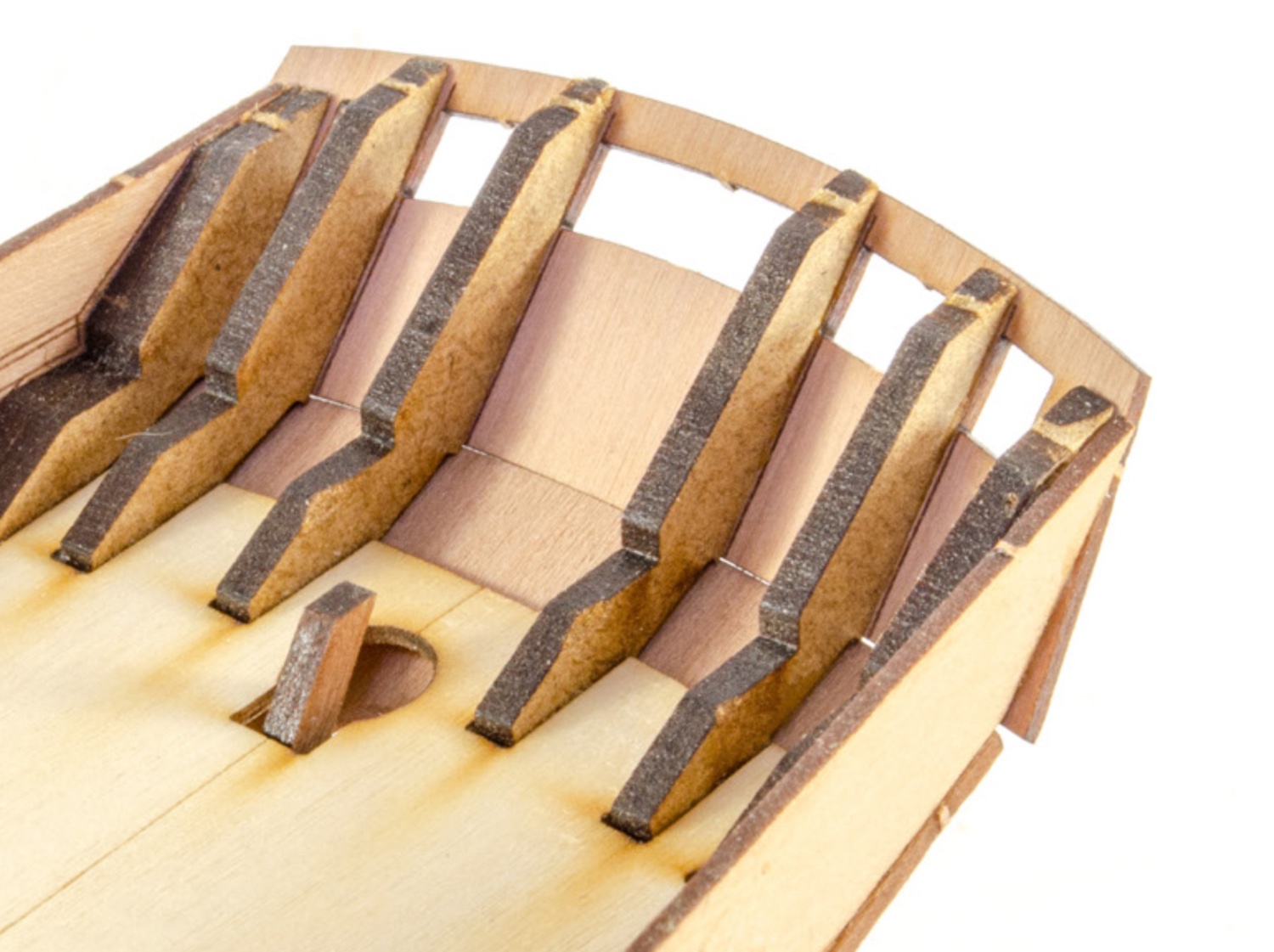
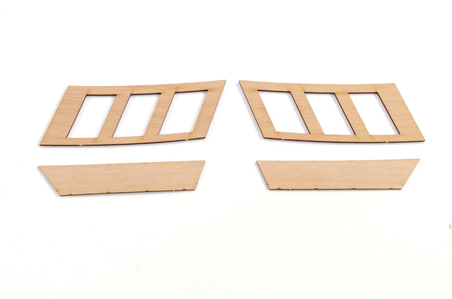
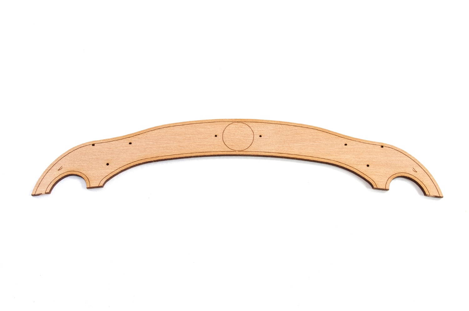
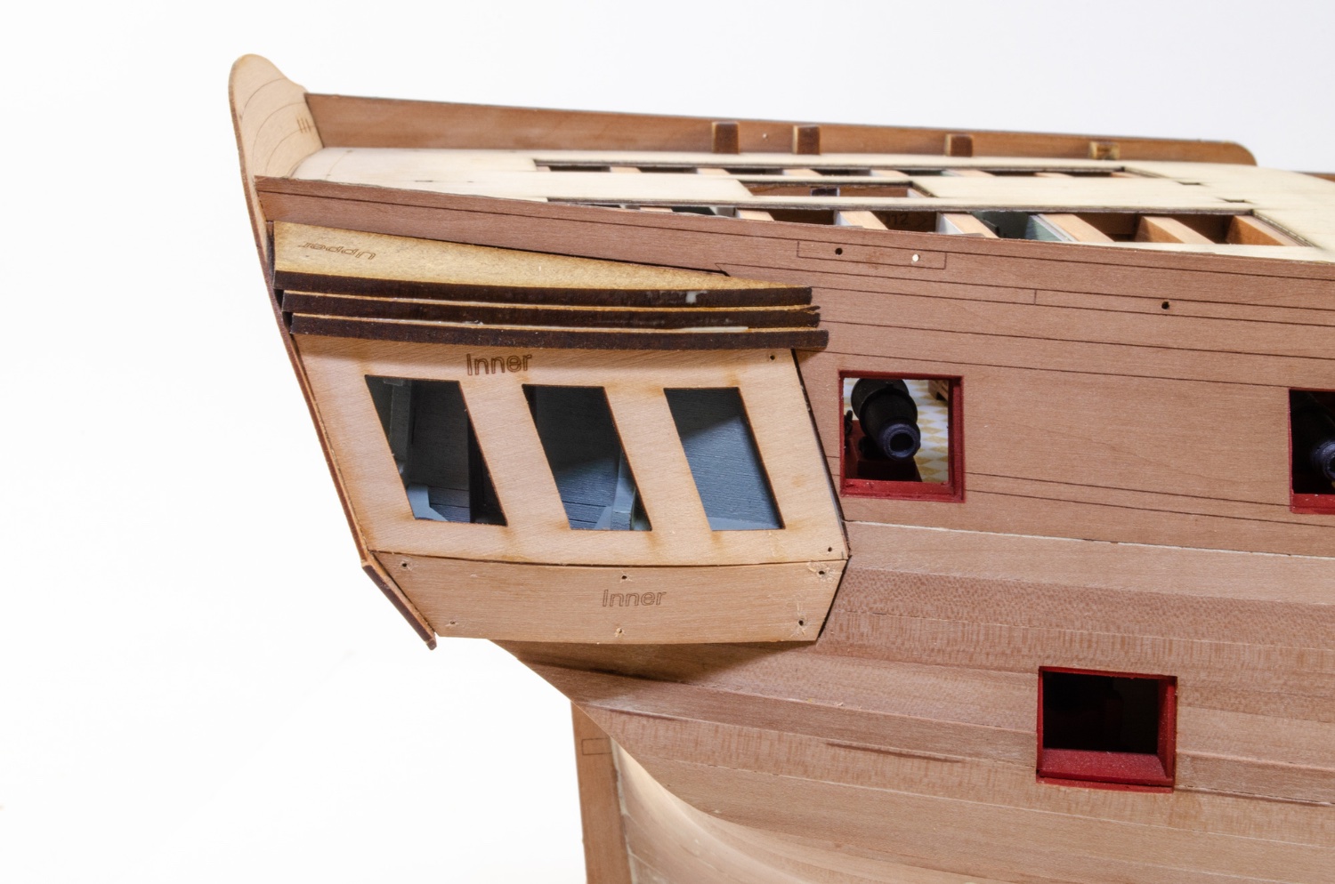
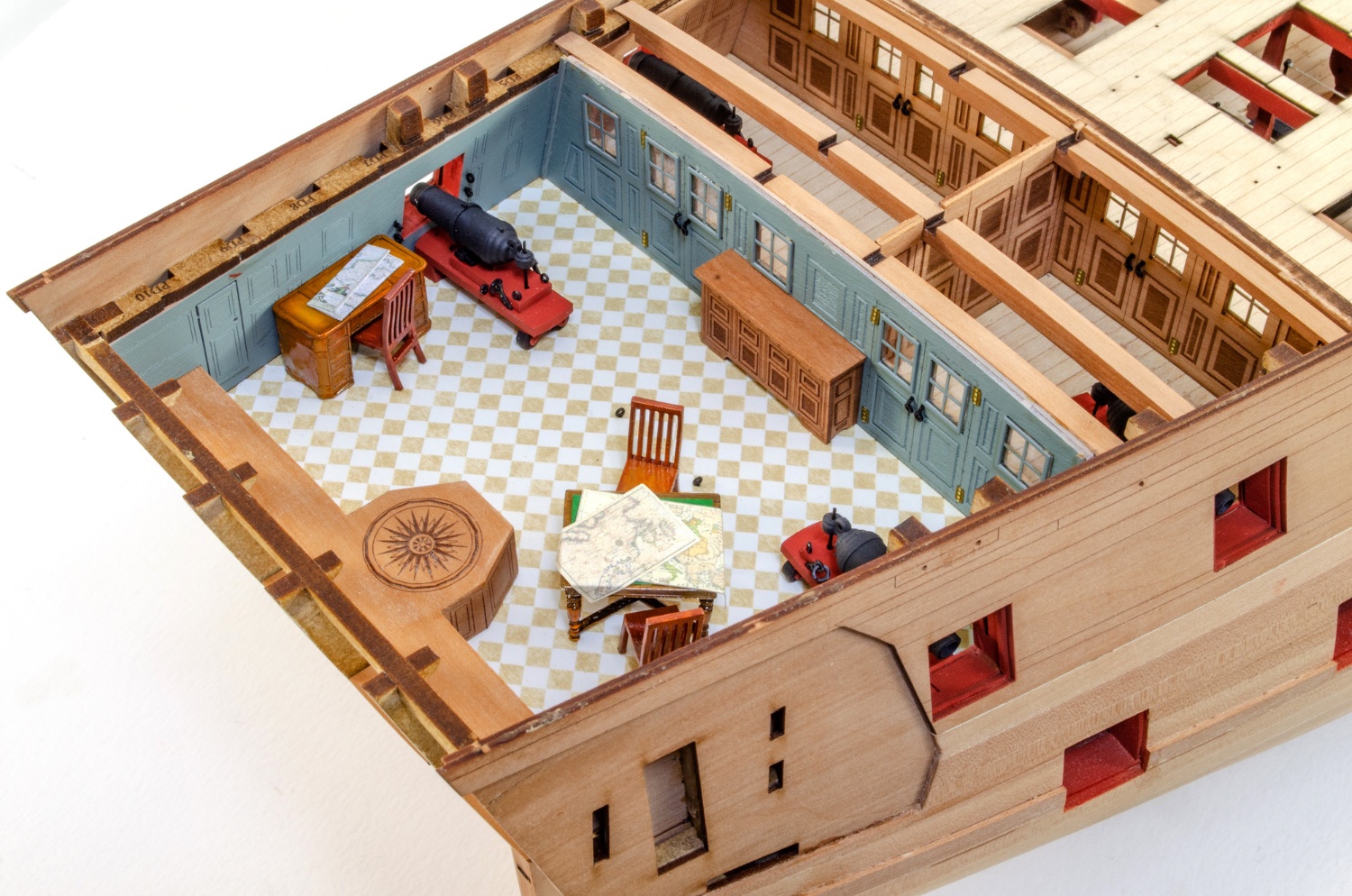
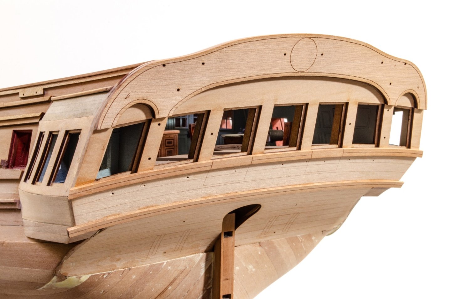
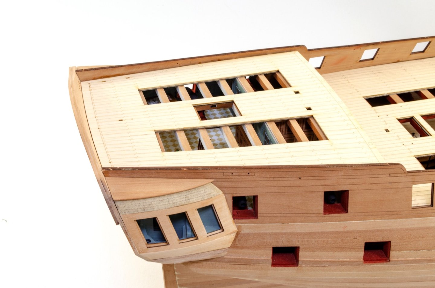
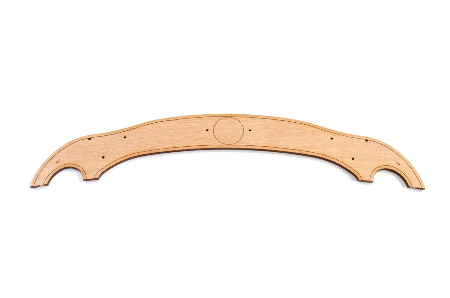
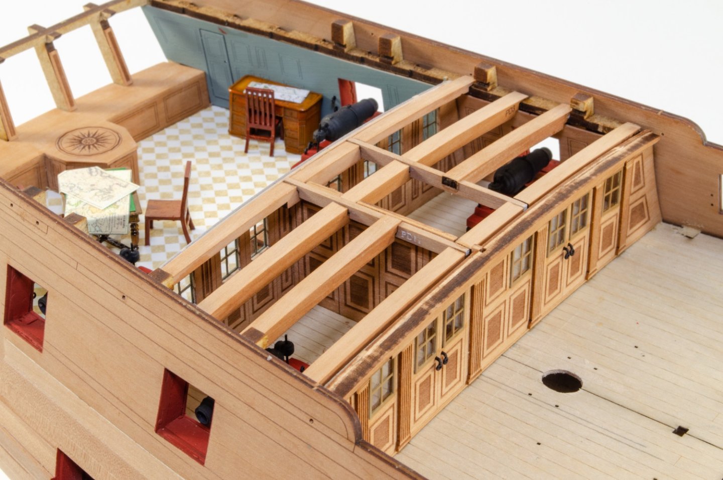
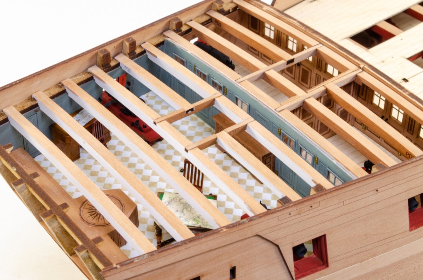
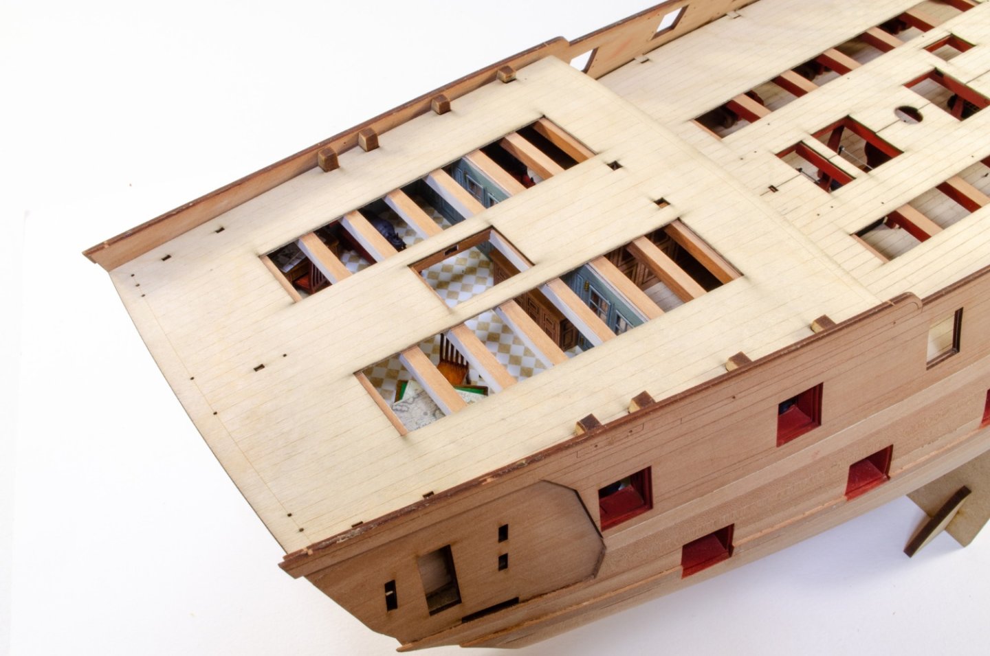
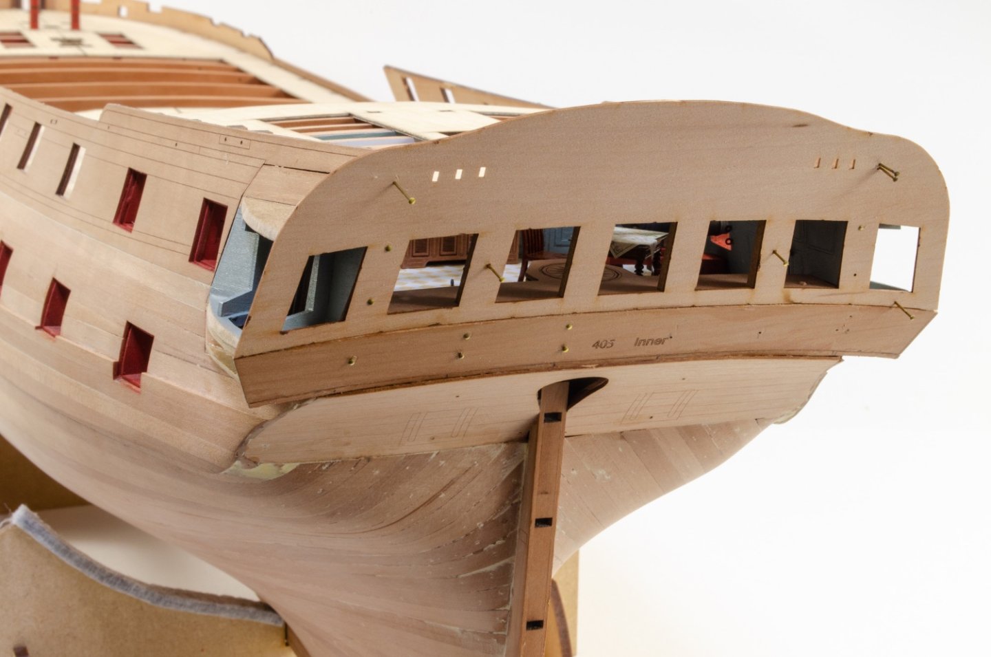
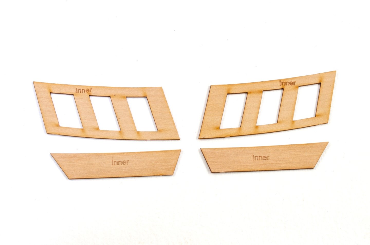
Another update as at least it's now looking a little different. Well, like it or not, the cabin areas now have to be decked over and here you see the beams in the fore cabin area, including the timbers for the original position of the skylight. This was likely moved rearwards when razed. And here you see the new skylight position over the main cabin, which sort of does make much more sense as that area can now be subject to some direct down sunlight. With all beams in place, the 0.8mm laser-engraved ply sub-deck is now installed, notched into the protruding bulkhead ears that you can see. With the poop deck now installed, it's time to turn attention to the quarter galleries. This always gives a hull some character and definition. Here you see the frames, now painted, being glued to the indents on the rear of the hull sides. The inner stern panel can now be fitted, as well as the counter. As with Sphinx, the quarters are sheathed in two layers of timber with the upper parts creating a recessed frame. Here are the inner skins for the galleries. And here is the stern up to this point. Three MDF layers are used to create the roof, except for a pear caping piece that's fitted soon. These will eventually be painted black and covered with laser-cut shingles. The reason for the layers is that it makes it easier to sand to the correct angles as you temporarily sit them on the hull side. After fettling, the finished roof will look like this.


- 473 replies
-
- 35
-
-
- Indefatigable
- Vanguard Models
- (and 1 more)
-
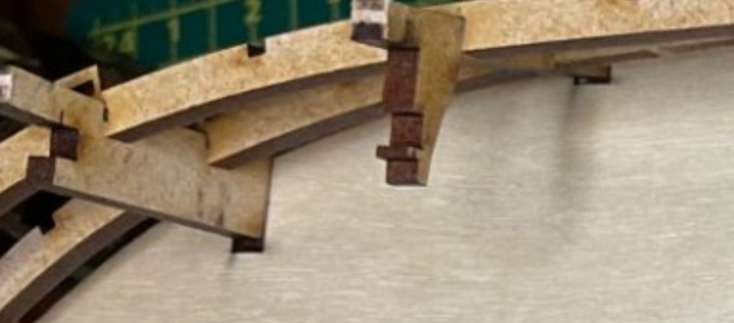
In fact, you can see the deck isn't properly located as it should be. Take a look here at the gaps between the ply deck slot and the bulkhead ears:
-
The comparison of the engraved deck to the ply sub deck is correct. The engraved part is smaller as it doesn't extend into the bulwark area. The problem you have with fitting the ply decks is definitely that the halves aren't pushed completely back into the slots in the bulkhead ears, no doubt. The deck width across each bulkhead I a set width, with zero variation between kit. Try using a jewellers file to remove the char from each ply deck slot, and also slightly bevel the upper, innermost part of the slot so that it catches the notch in each bulkhead ear. I absolutely guarantee that this is the cause. I've seen this a couple of times before and know this is the issue. Just be careful in your test fitting to make sure the deck halves are slotted in 100%.
-
Doesn't it feel great to have finished something as complex as Sphinx! Well done, and it was definitely a nice move in starting over too. If I have one suggestion it would be to re-angle and tidy up the hammock cranes and rope along the gangways. ✌️
- 476 replies
-
- 5
-
-
- sphinx
- vanguard models
- (and 1 more)
-
It'll be a little difficult on a fully rigged ship. You can open things up more if you wanted though.
- 473 replies
-
- 7
-
-
- Indefatigable
- Vanguard Models
- (and 1 more)
-
I re-took the photo of the cabin area as there was too much glare on the deck and the background was dirty. So, here it is.

- 473 replies
-
- 34
-
-
-
- Indefatigable
- Vanguard Models
- (and 1 more)