James H
-
Posts
6,144 -
Joined
-
Last visited
Content Type
Profiles
Forums
Gallery
Events
Everything posted by James H
-

HMS Granado 1742 Kit - CAF Model - 1:48 Scale
James H replied to cafmodel's topic in Wood ship model kits
That looks real good Tom. I hope your supply issues are sorted very soon. -
Member banned. Previously registered under different name and banned for supporting piracy.
- 1 reply
-
- 2
-

-

-
Member banned. Previously registered under different name and banned for supporting piracy.
- 1 reply
-
- 4
-
-
-
Eugen, that looks superb and beautifully clean work. When do you think this one will be finished?
- 216 replies
-
- 5
-
-
- masterkorabel
- ships
- (and 3 more)
-
One of your pics is missing. Seems to be linked to an account at Microsoft. You can upload all your pics to MSW so you won't lose any or have broken links.
-
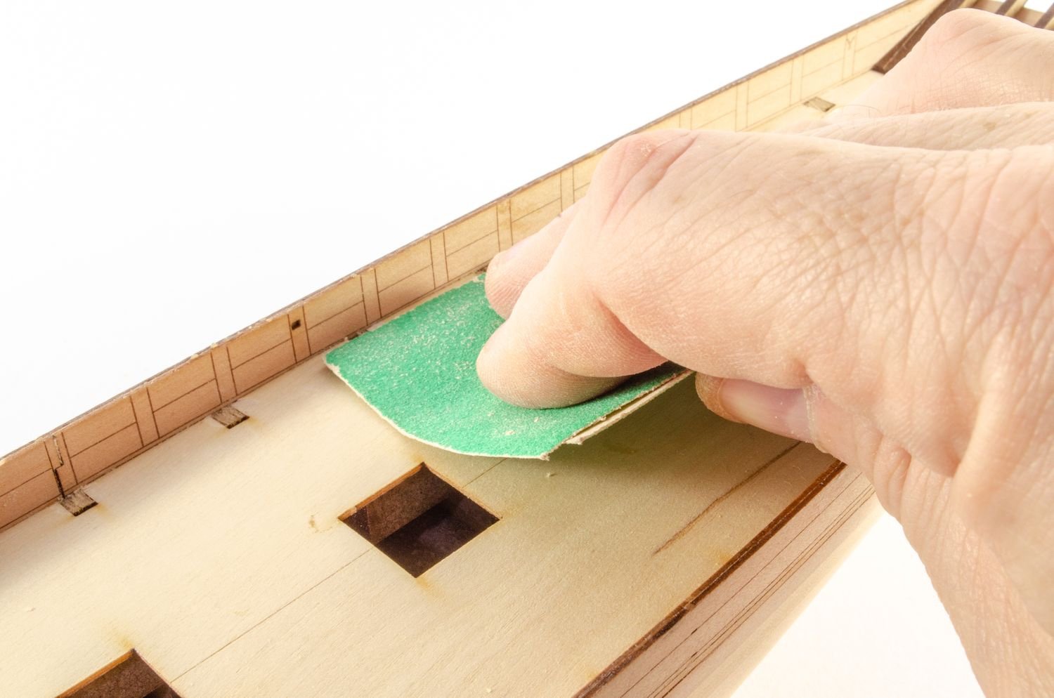
Just sand and fill, sand and fill. Most of this is under paint anyway and if you're unhappy with anything above paint areas, you can always extend the scheme a little. That's not looking too bad at all. Use your fingers to feel for imperfections, then sand as you feel anything.
-
I'm pleased that I did my bit with the instructions build and that it's easy enough to follow. God help me when I have to do the pics for Indefatigable! 😂
- 32 replies
-
- 3
-

-
-
- Nisha
- Vanguard Models
- (and 1 more)
-
Don't forget, PayPal also lets you spread purchases too. Depending on region, stuff can be spread between 3 and 5 months too. Indy will be very reasonable in cost, especially over the time it will take to do this kit justice.
-
I know cost is relative, but if we take a look at something very pertinent, then we get a better idea: Caldercraft 1:64 HMS Agamemnon. A kit that uses the legacy POB methods, with dummy barrels for the lower gun deck, nothing in the way of laser-cut/engraved parts. Many generic fittings and also the gun port positions are determined with a paper template, with the exception of quarterdeck ports that are cut into the inner bulwarks. Finishing and detail timber is generally walnut with Tanganyika for decks. Aggy also doesn't have a lower gun deck at all. The main gun deck is complete, but stops fore of a ply bulkhead so doesn't extend to stern cabin areas as they don't exist in kit. In all, Agamemnon is an amazing kit, and we've seen some fantastic builds of her. What does she currently retail for? £935 direct from Caldercraft. This is a kit that's now 22-23 years old. Vanguard Models 1:64 HMS Indefatigable. A kit that uses new design techniques with gun ports built into the hull framing. Stern cabin with internal engraved details (chequered floor, panelling etc), accessible quarter galleries with seats of ease. Stern cabin windows can be posed open or closed. Complete main gun deck with option to plug the gun carts into position so they don't come adrift accidentally. No generic parts. All guns on kit are designed to be the exact ones, printed in matt black resin, complete with George III emblems. Other 3D print parts include a proper scale belfry, Brodie Stove (in 4 parts), anchors, carronades/wheels, and also some rudder parts. 10 thicknesses of laser cut sheets. Planking will be in pear, and not walnut. There really is a price premium for going with the much better pear. Less brittle, less fibrous, finer grain and more realistic in colour. Deck planks will be either Red Alder or maple, depending on supply situation at time. To assist with painting, main gun barrels will be positioned after hull painting, and carronades are designed to retract into the hull until the externals are painted, then they can be pulled out into position! Detailed bulkhead screens for cabin. Deck beam positions are also to scale and in scale position, and do not relate to the MDF bulkhead positions. As with other VM designs, a rabbet is built into the keel, allowing easier plank positioning. Multi-layer channels to simulate the edging of the real thing. Engraved ply sub decks to assist with planking. Five mini kits for each of the ship's boats. Laser cut acrylic window panes. Laser cut and engraved acrylic stand with two-colour nameplate. Large and heavy full colour assembly manual detailing every aspect of construction and providing tips. Of course, Aggy is a 64-gun, but is around the same size, more or less to the razée Indefatigable. Indy just loses the razed areas, but it actually longer than Aggy due to the flying jibboom. Price? Tentatively around £1000. A whole 23yrs after Caldercraft's kit was released.
-
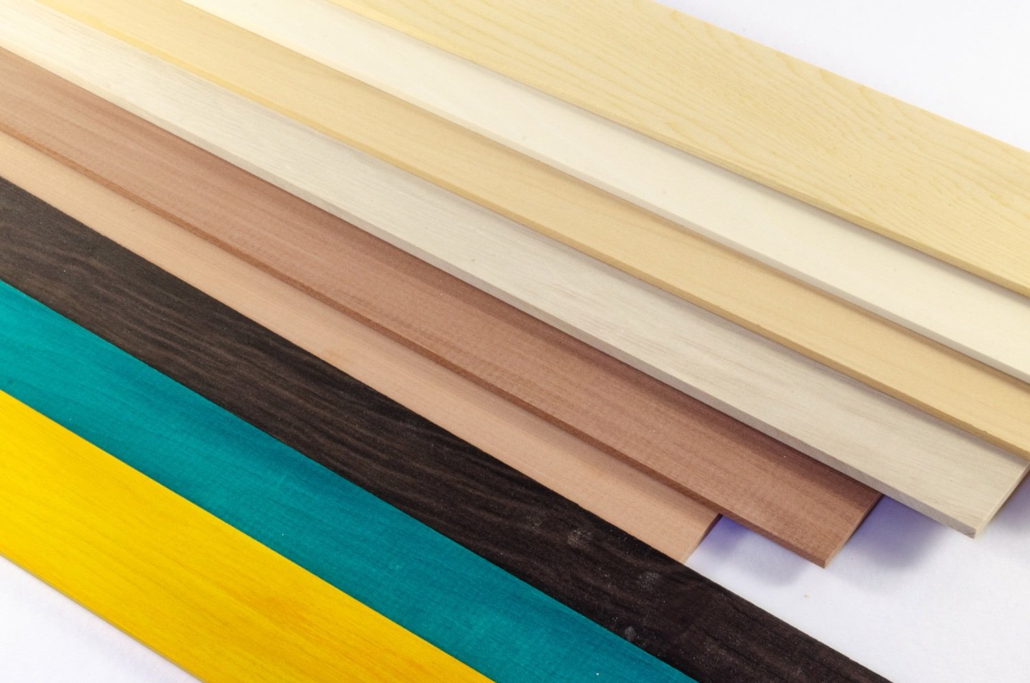
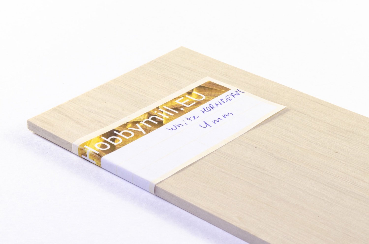
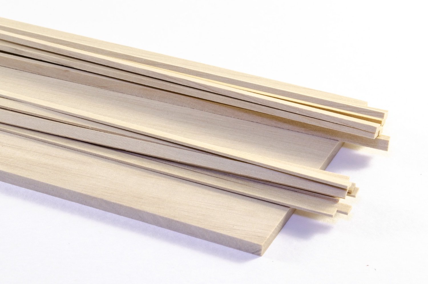
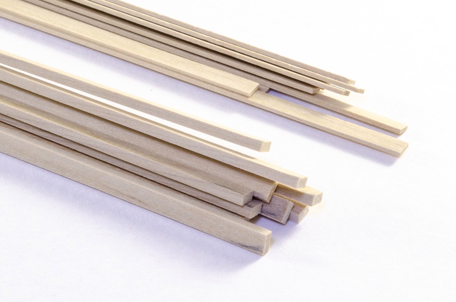
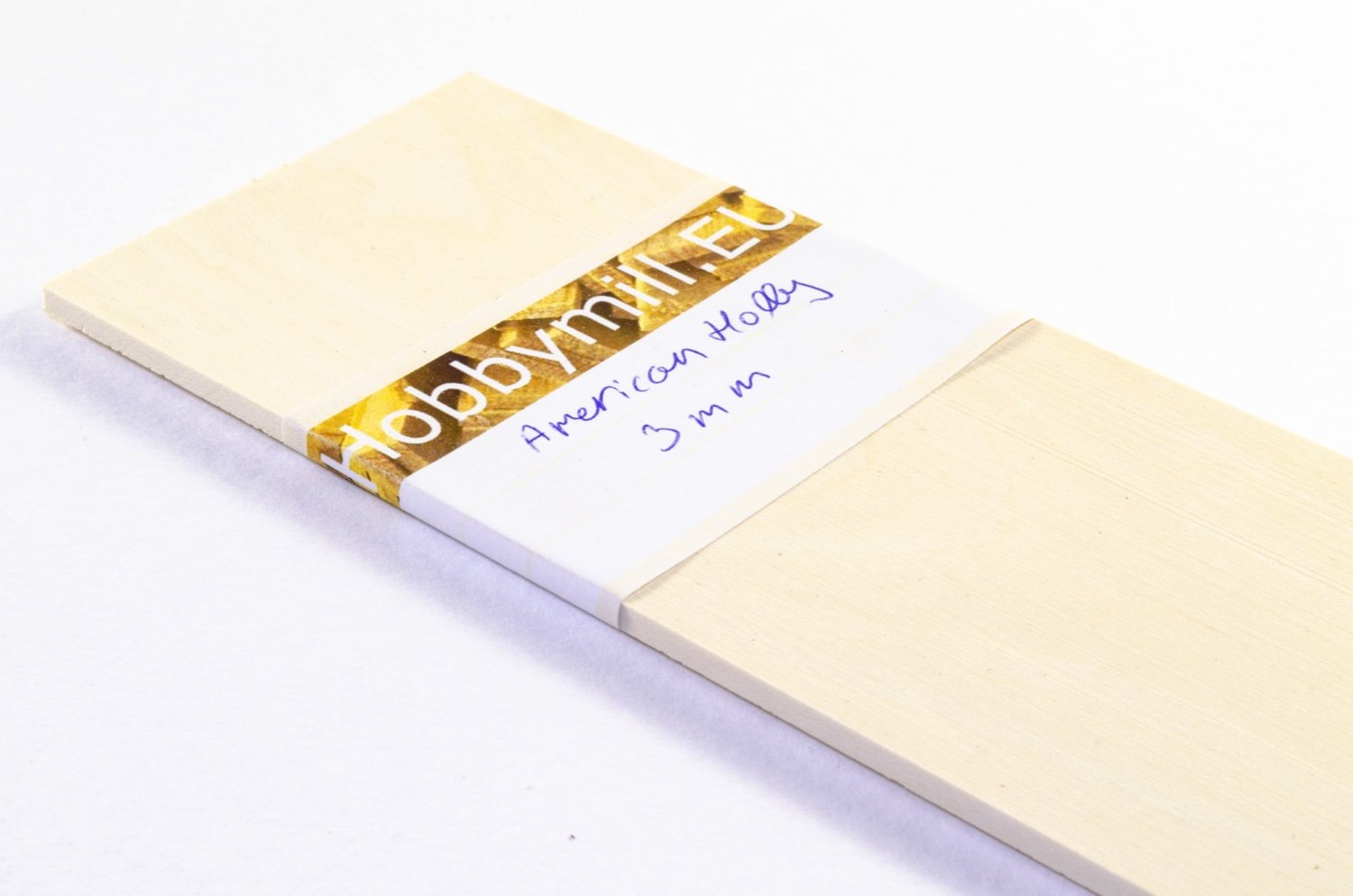
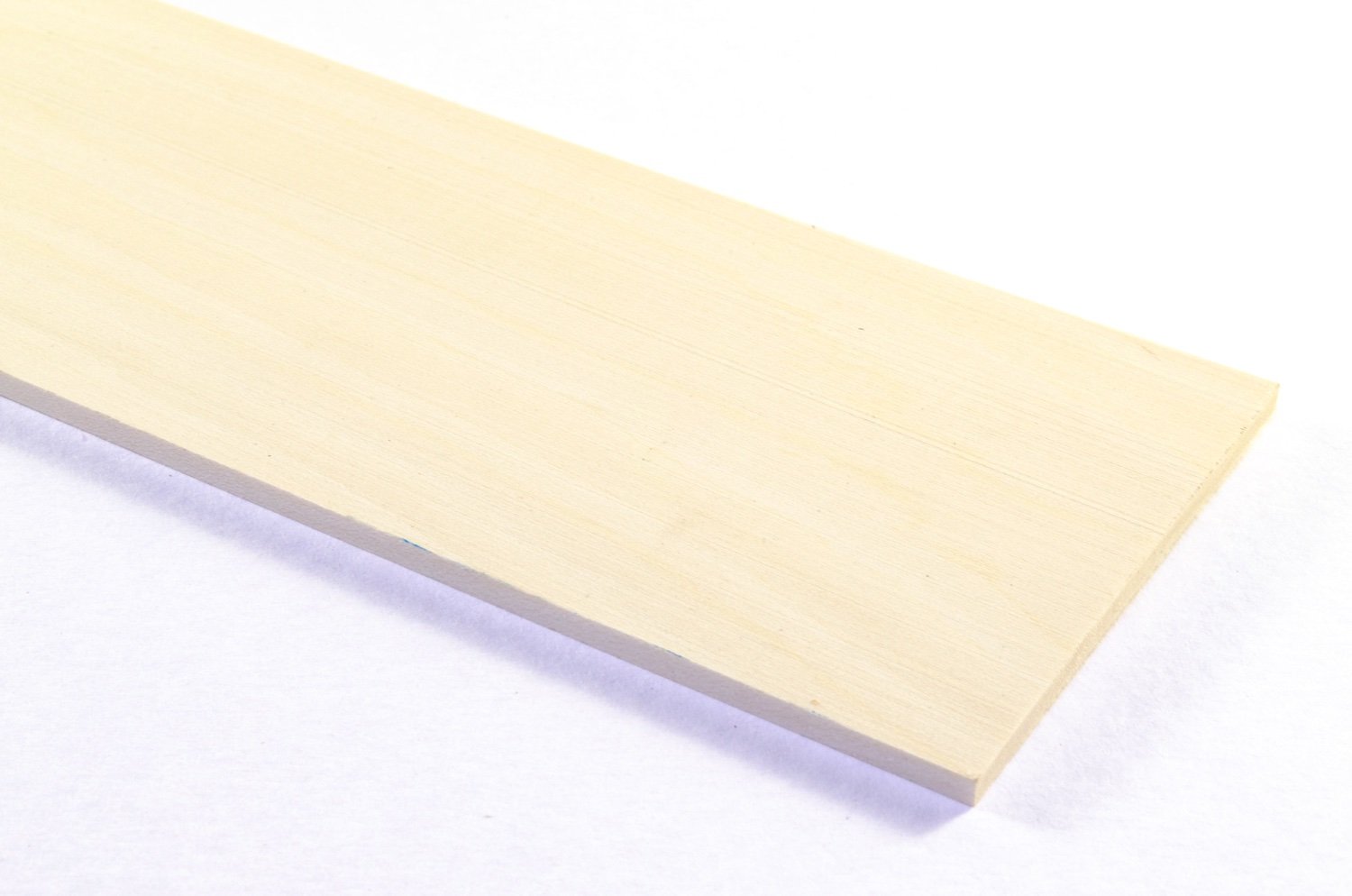
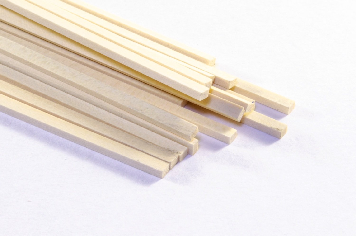
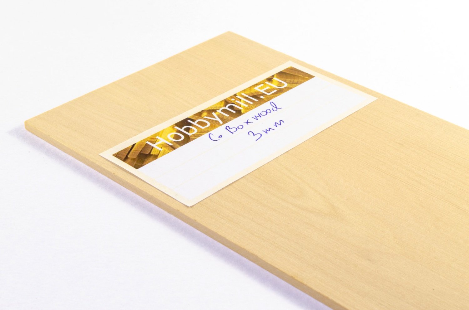
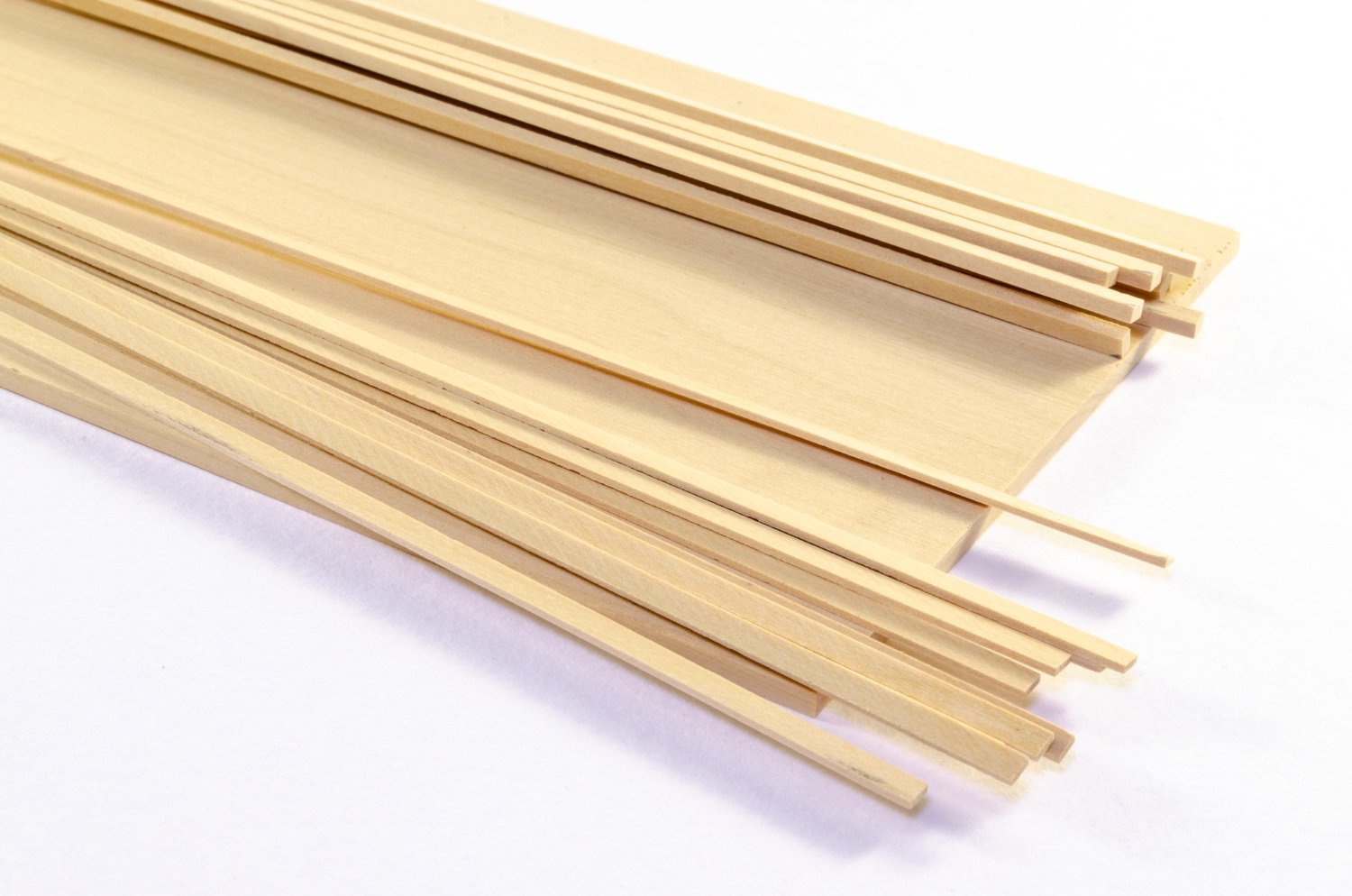
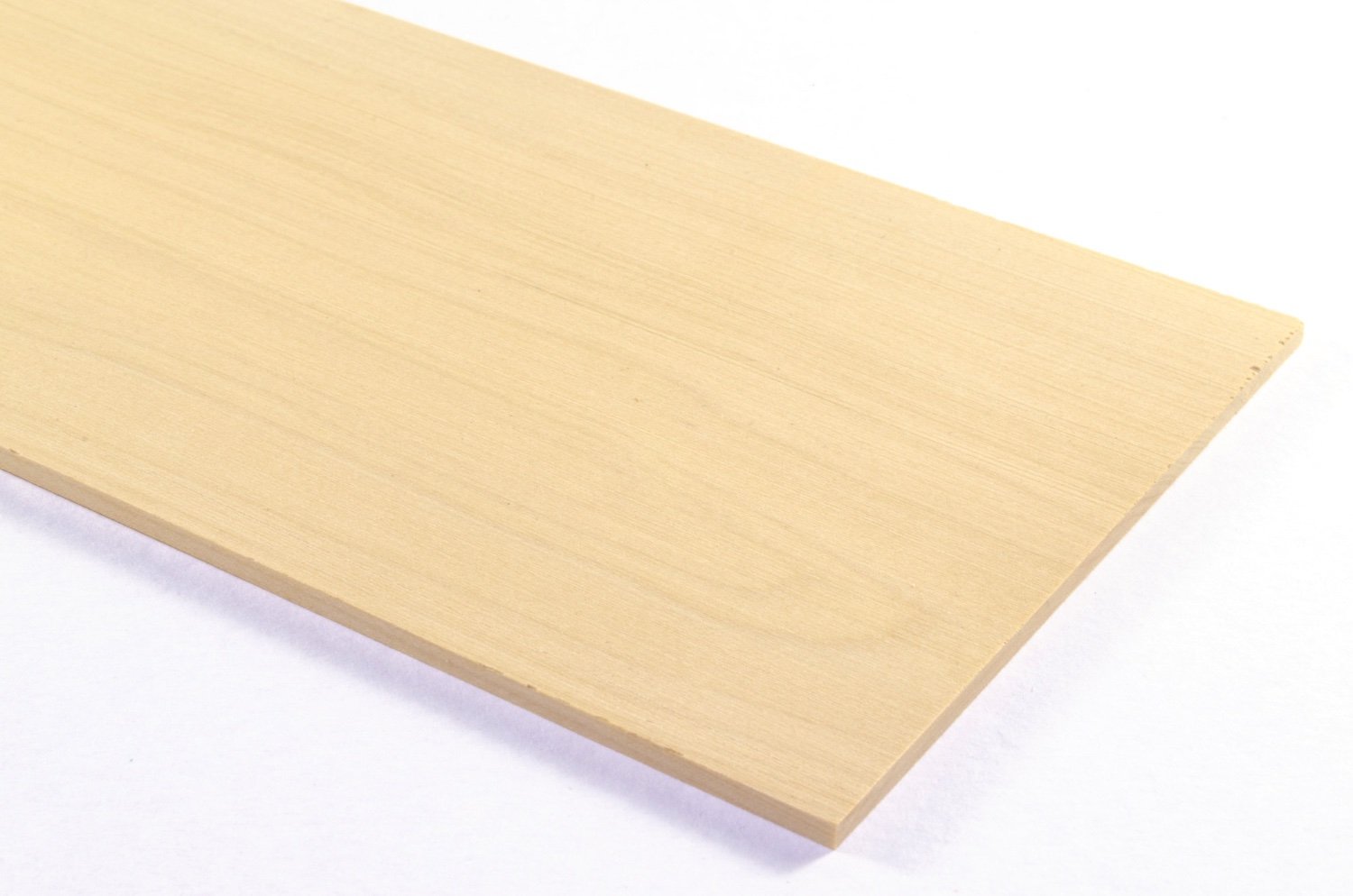
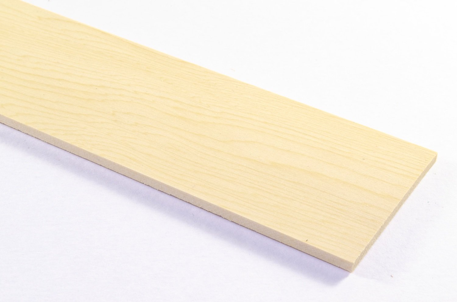
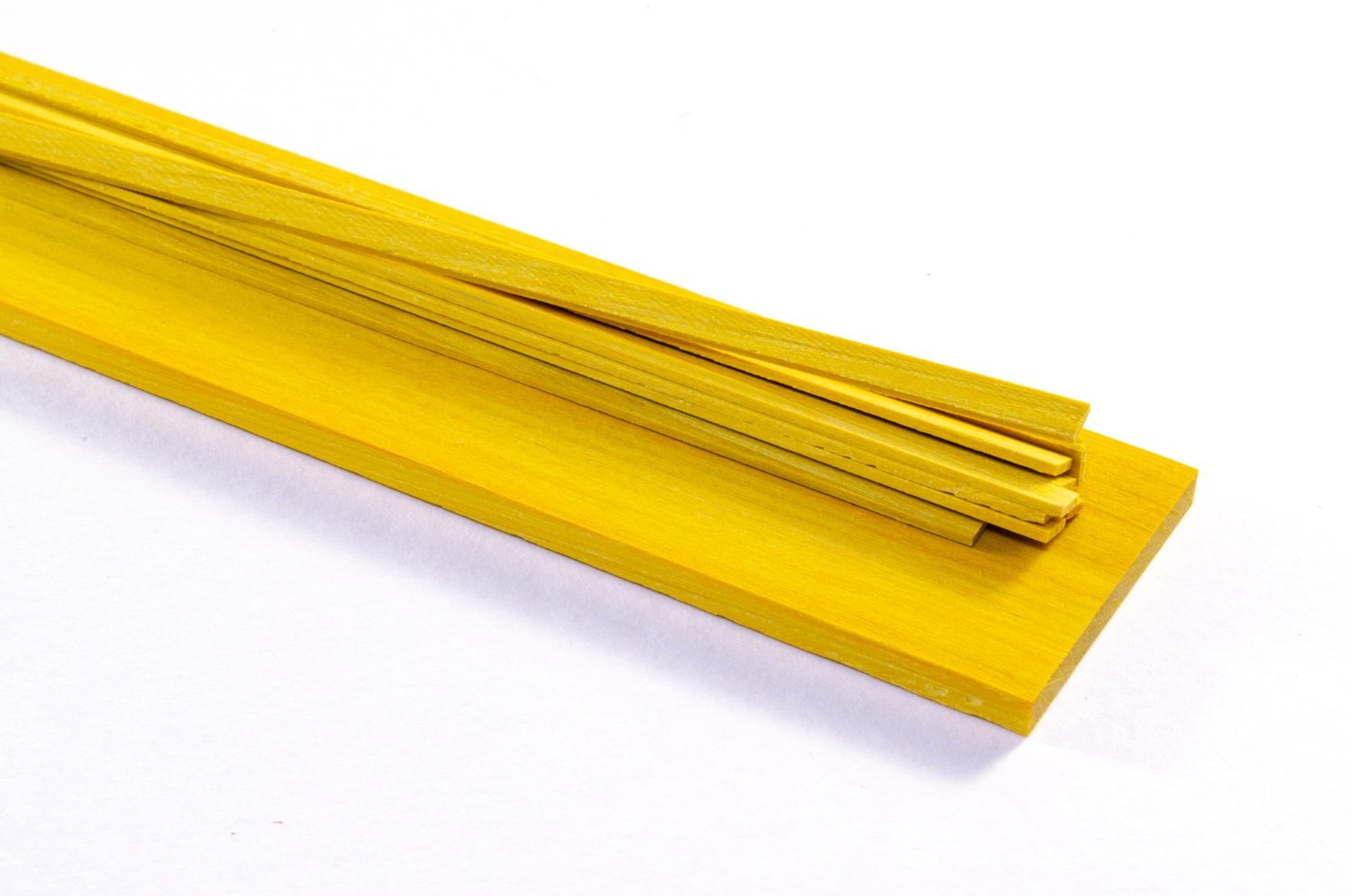
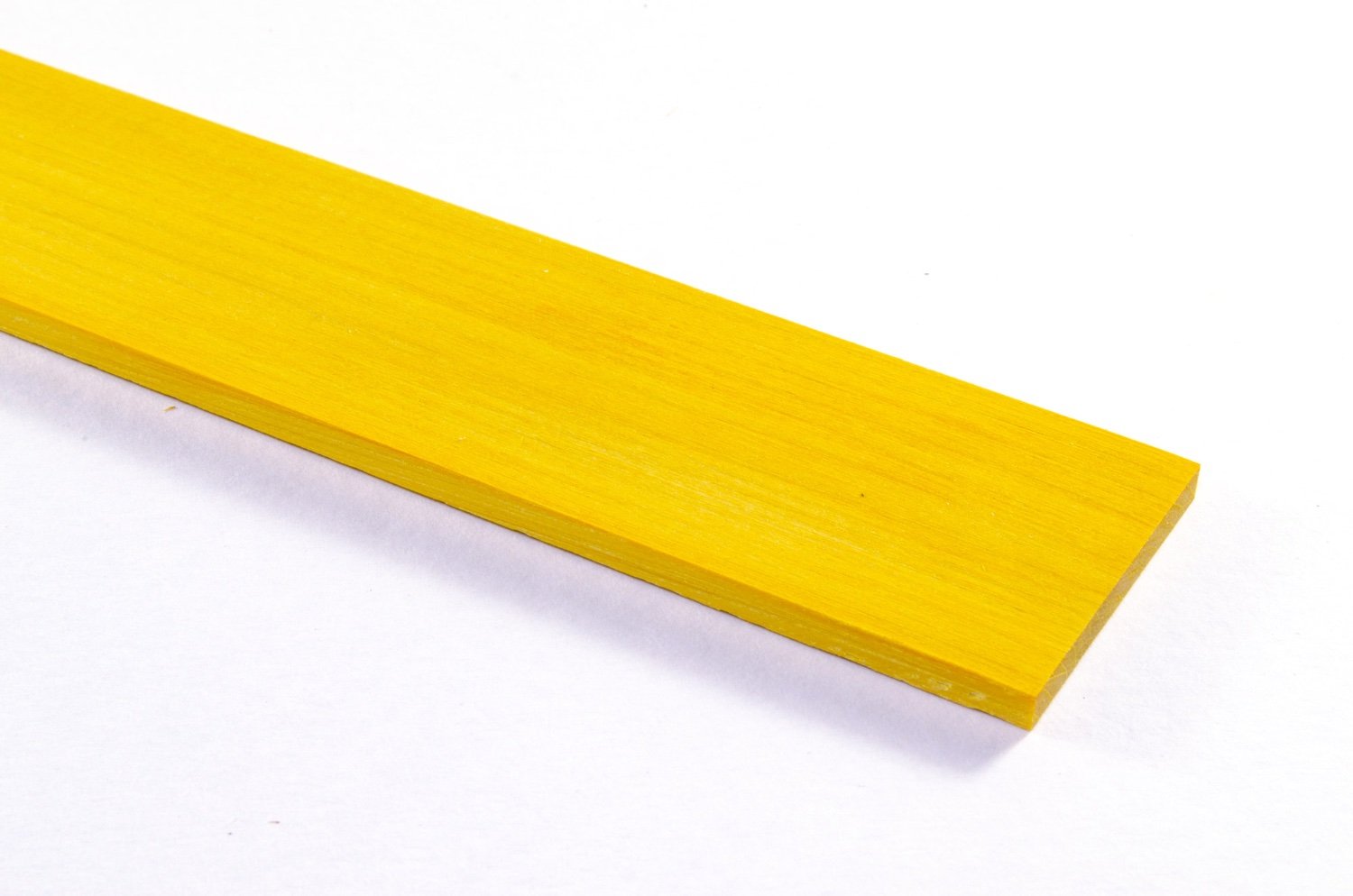
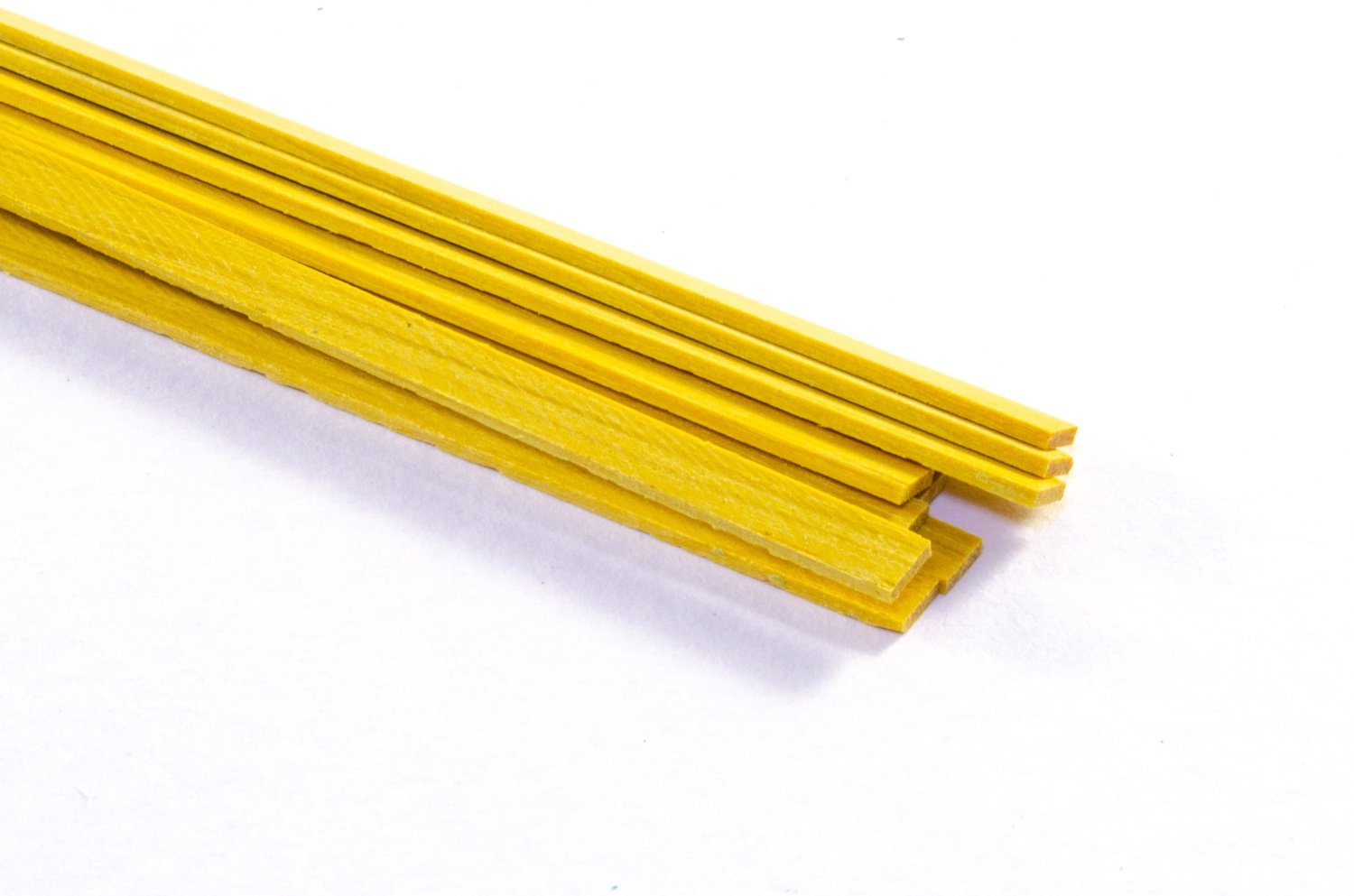
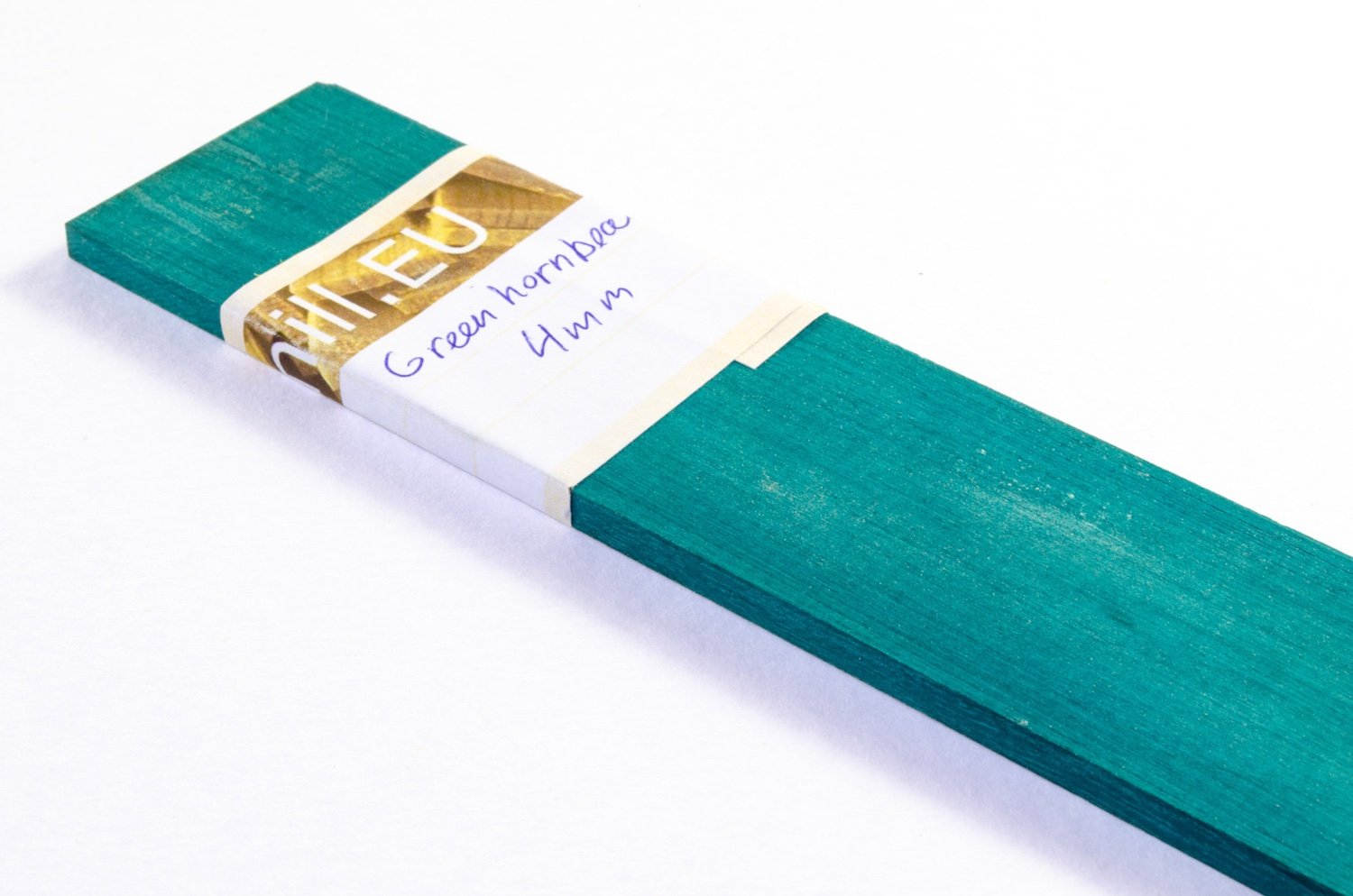
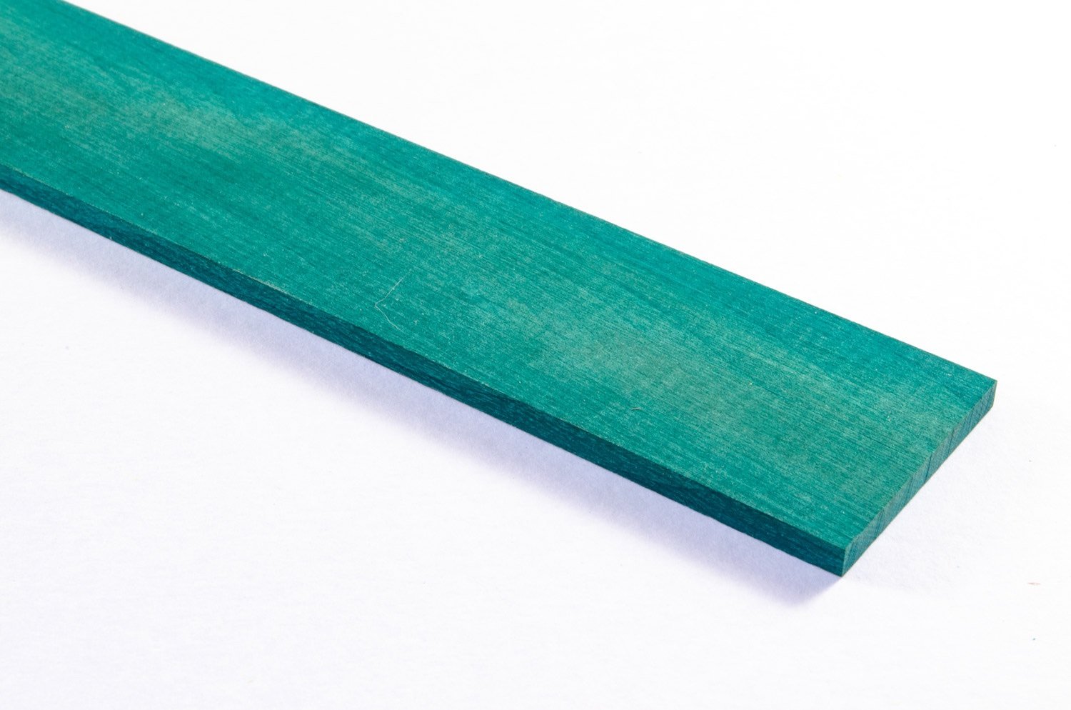
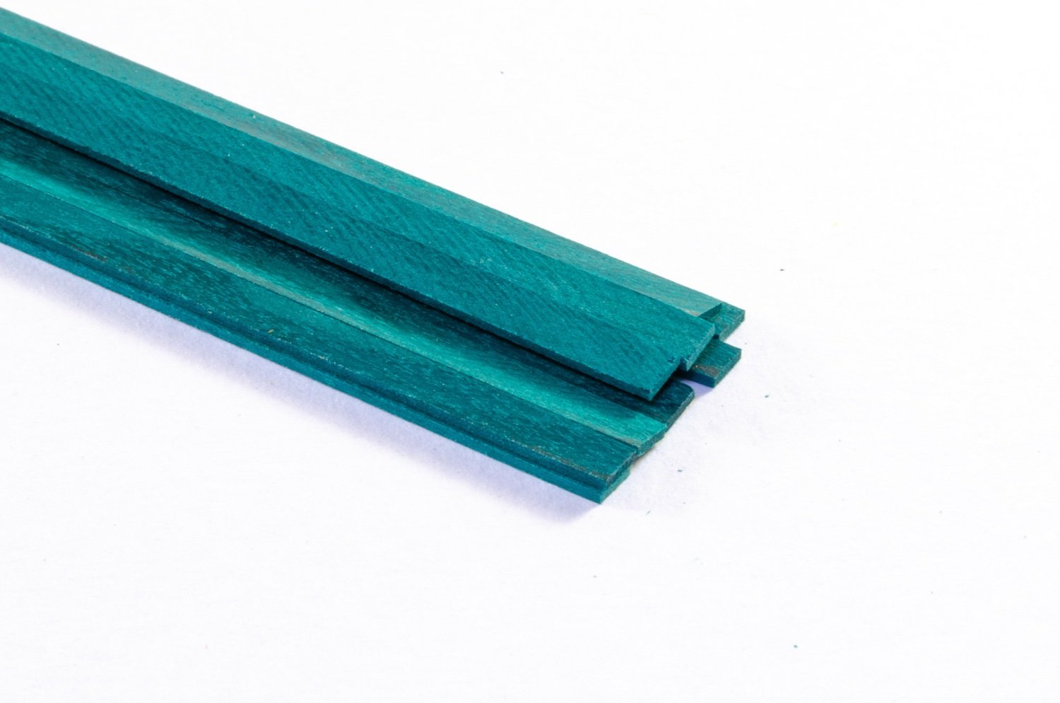
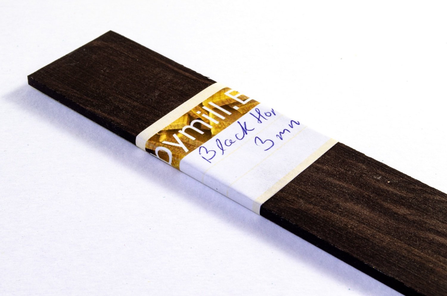
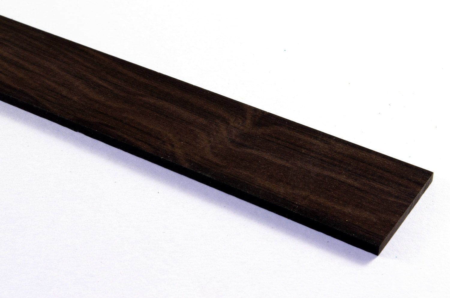
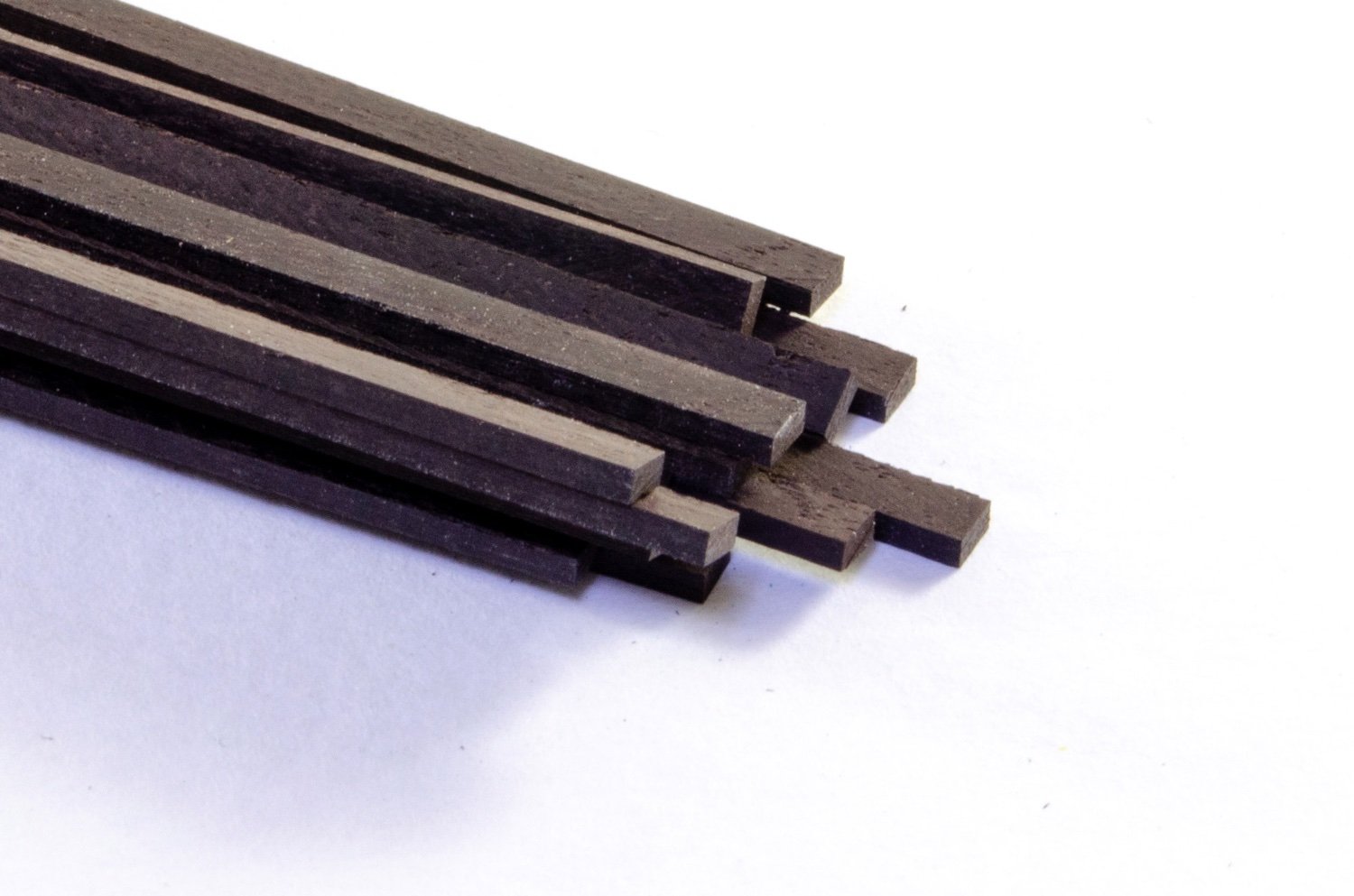
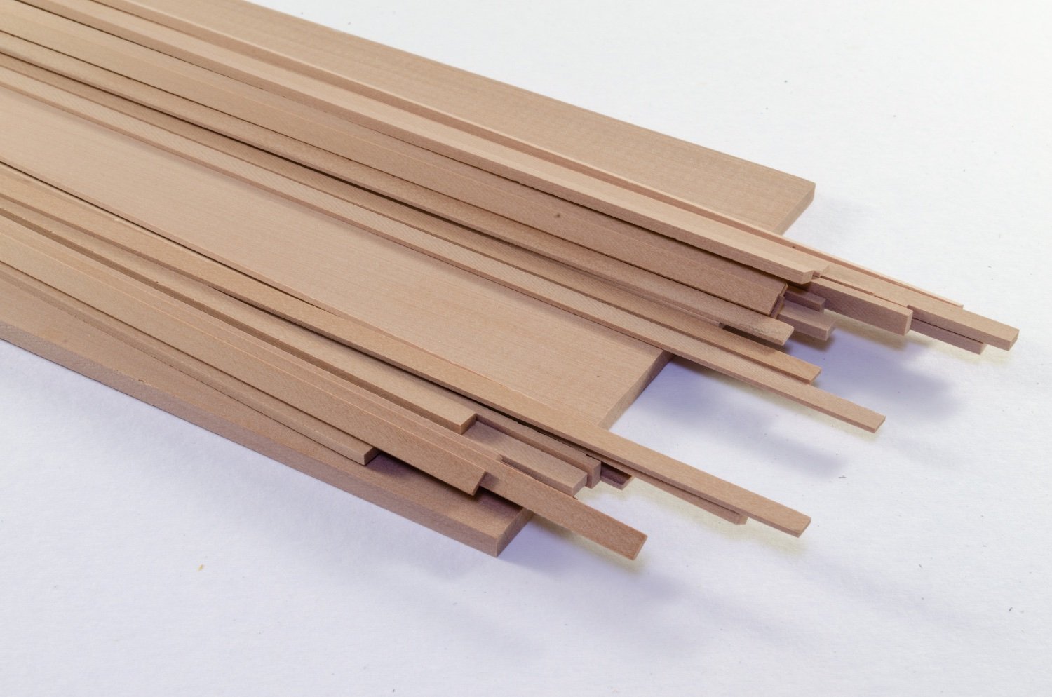
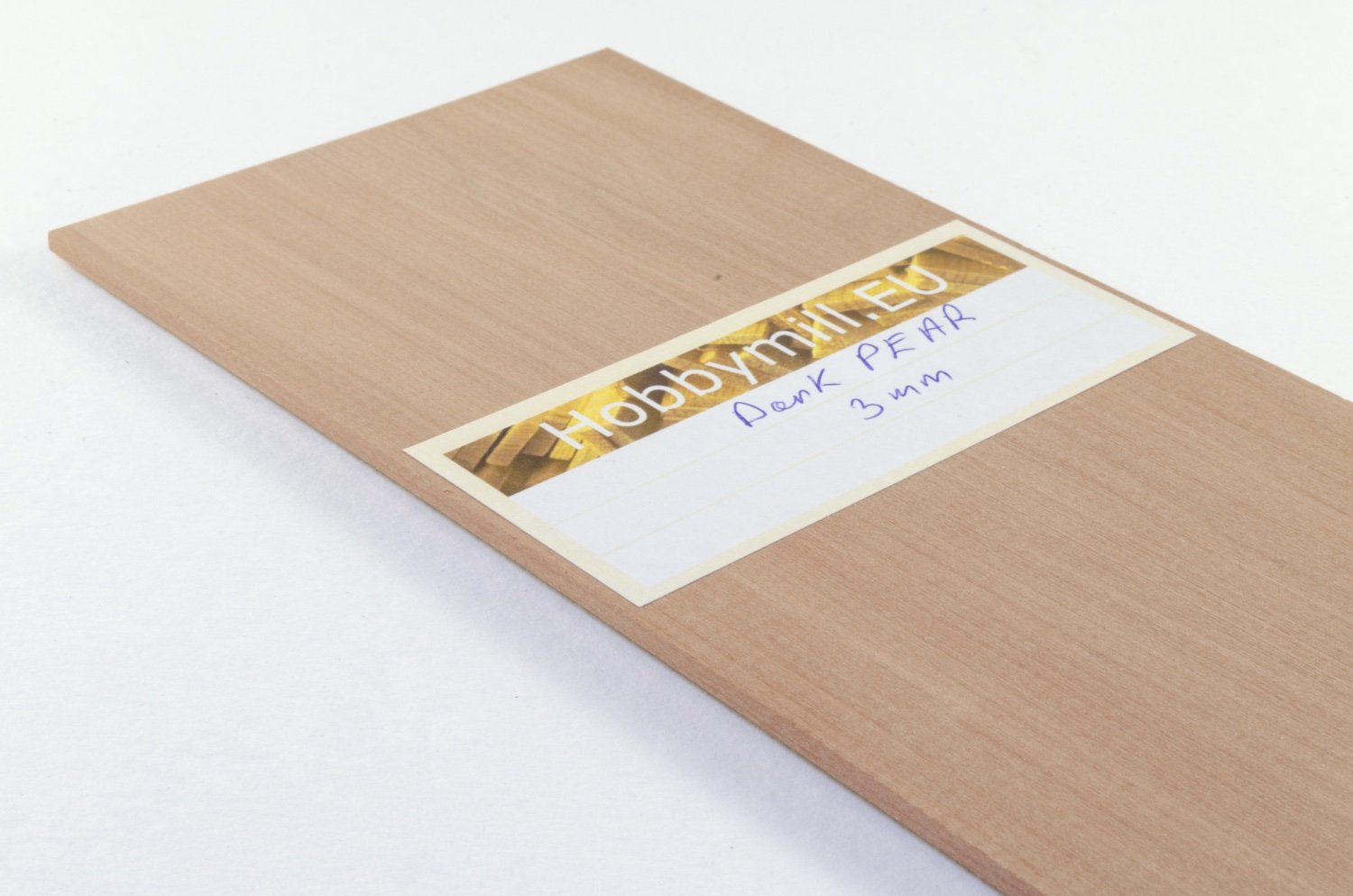
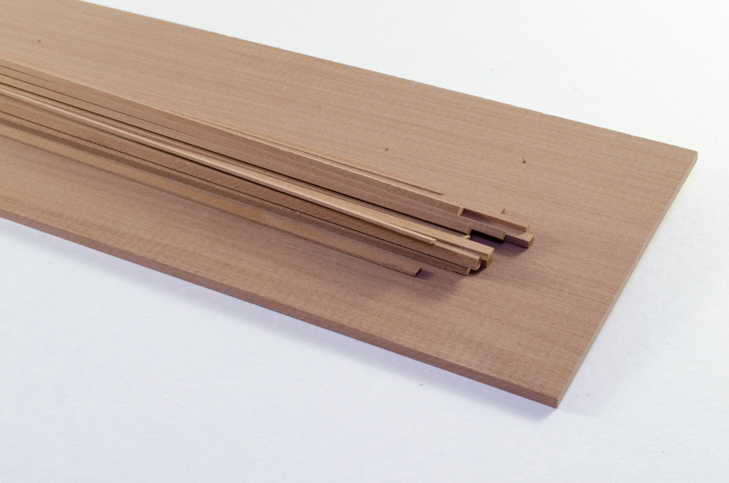
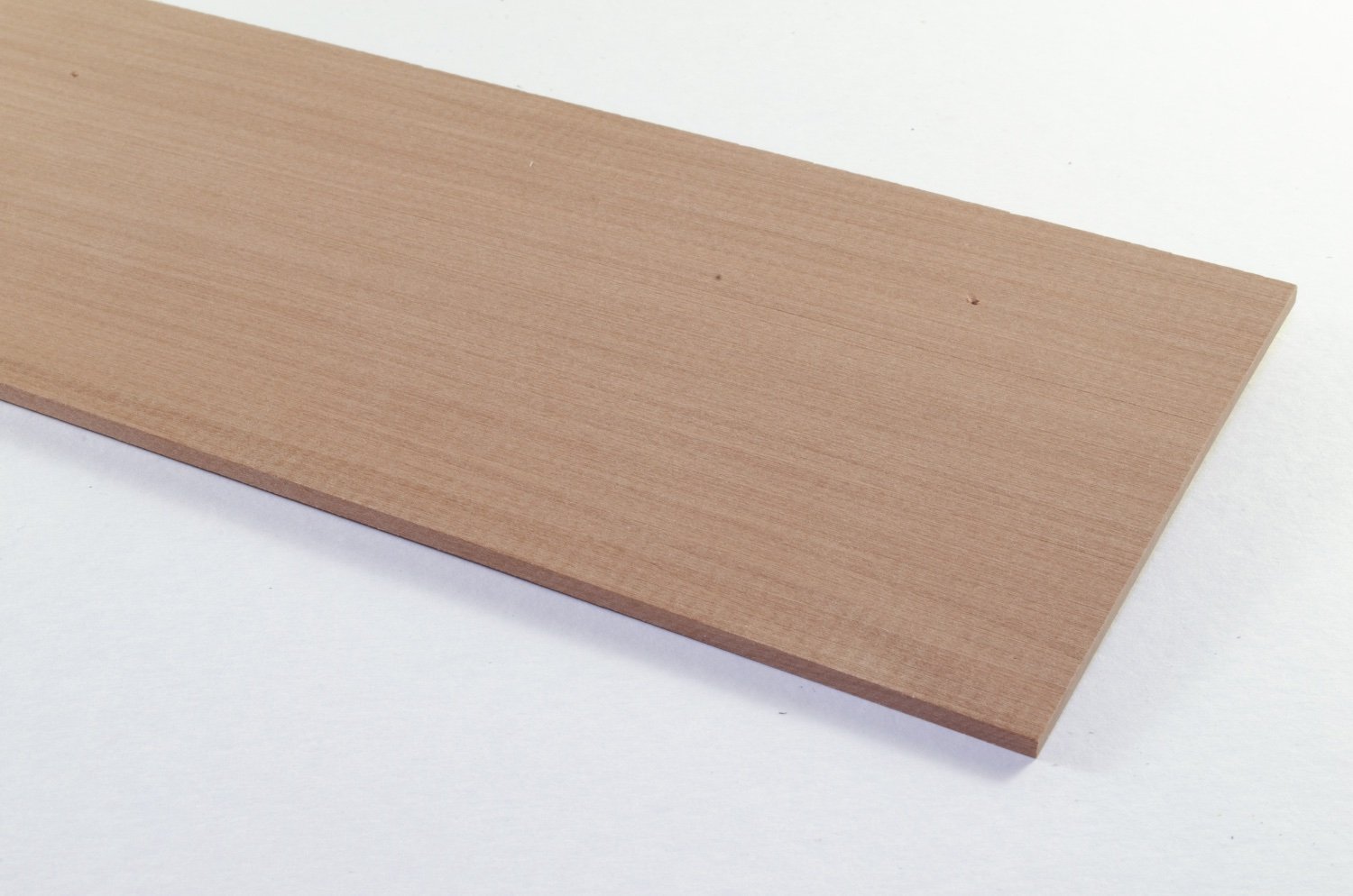
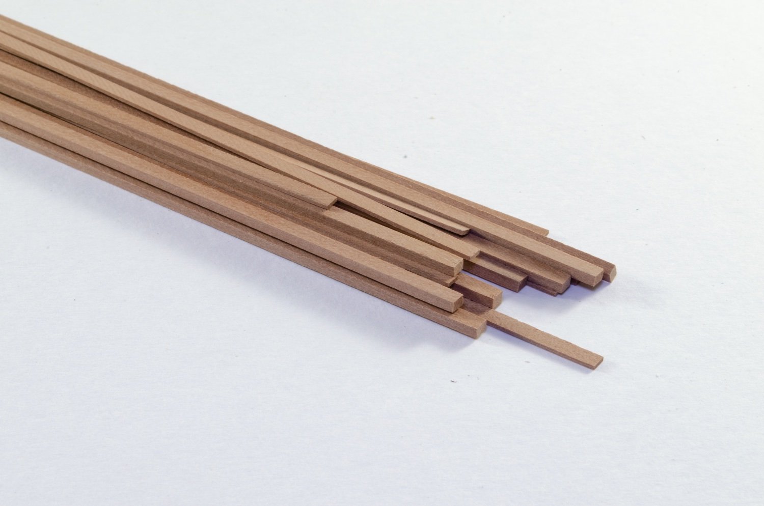
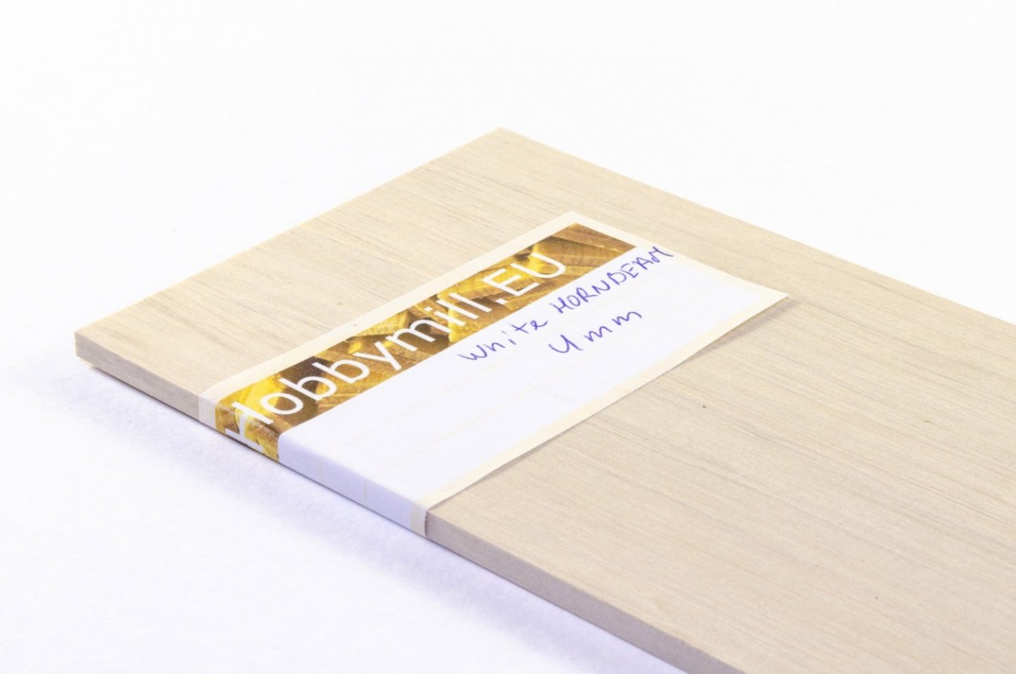
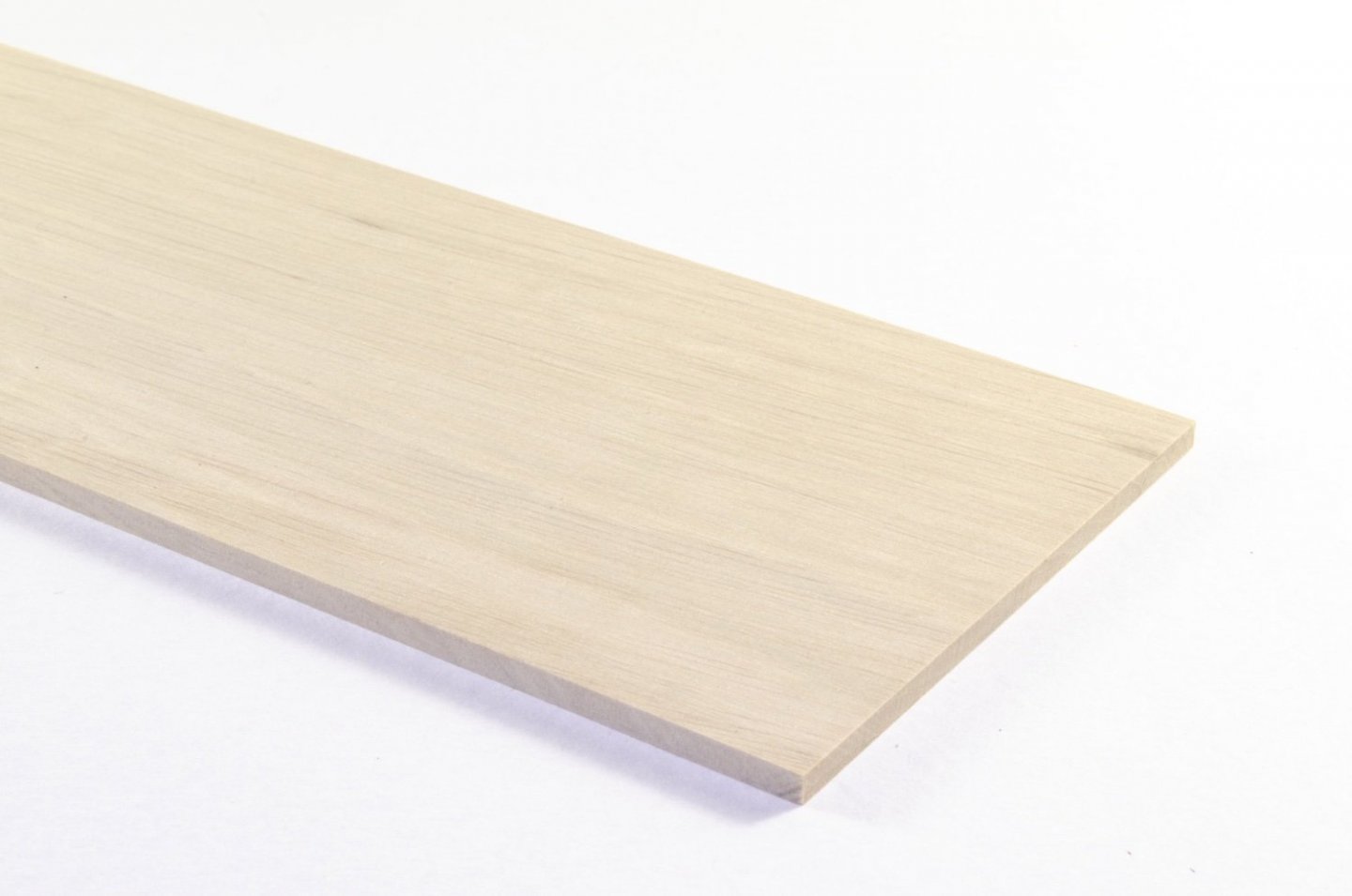
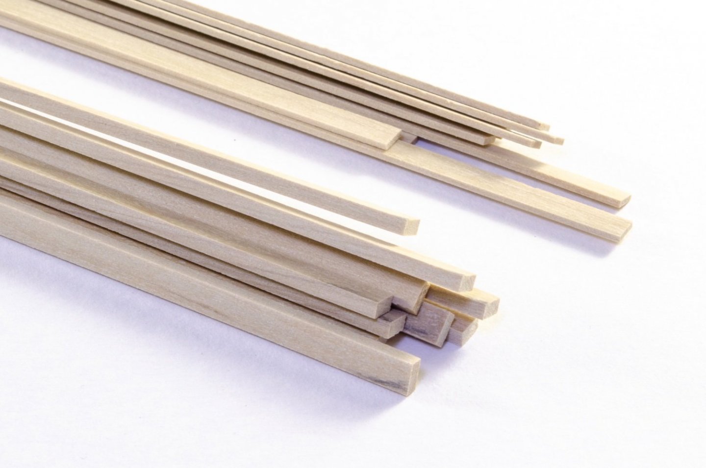
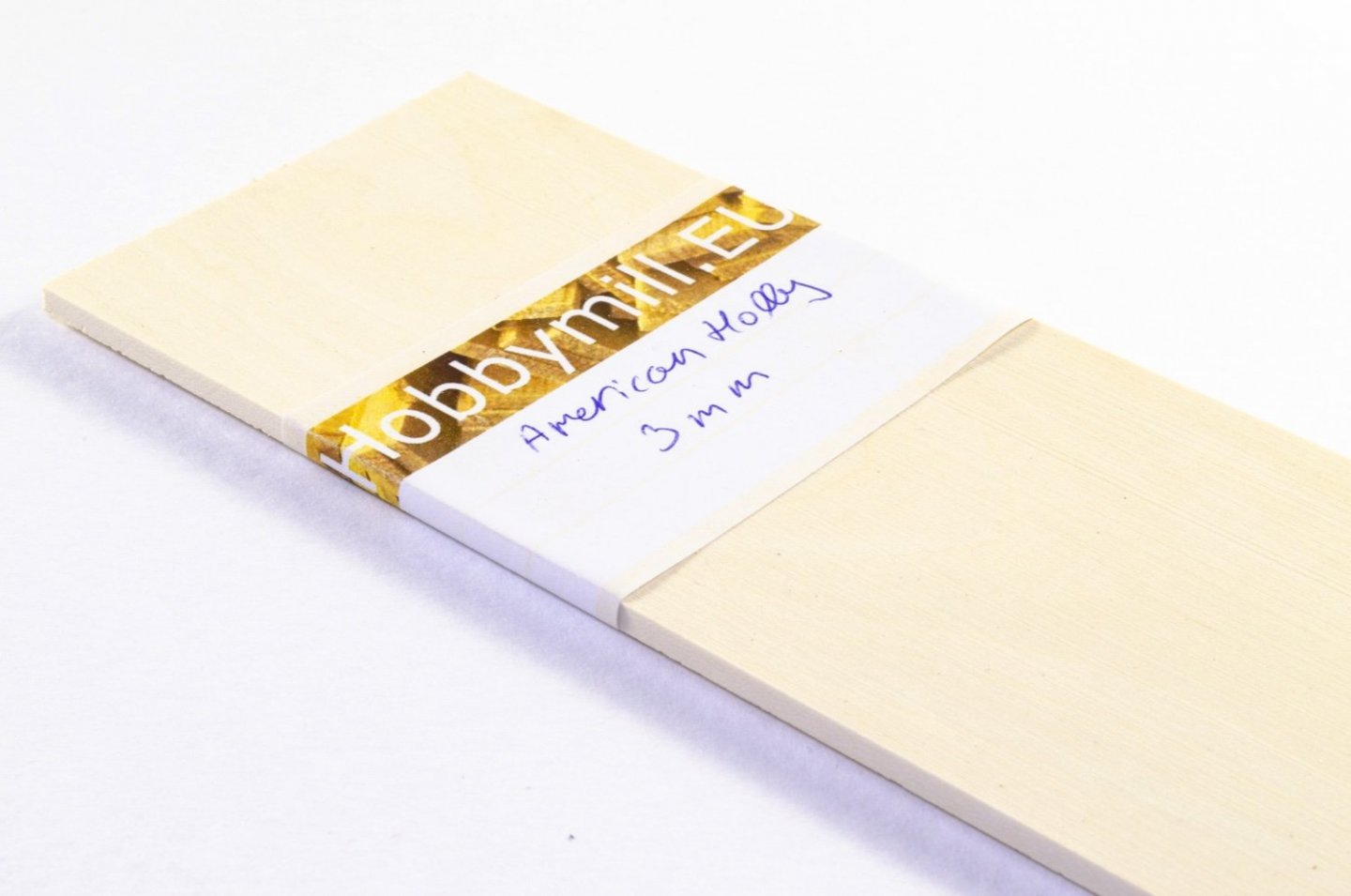
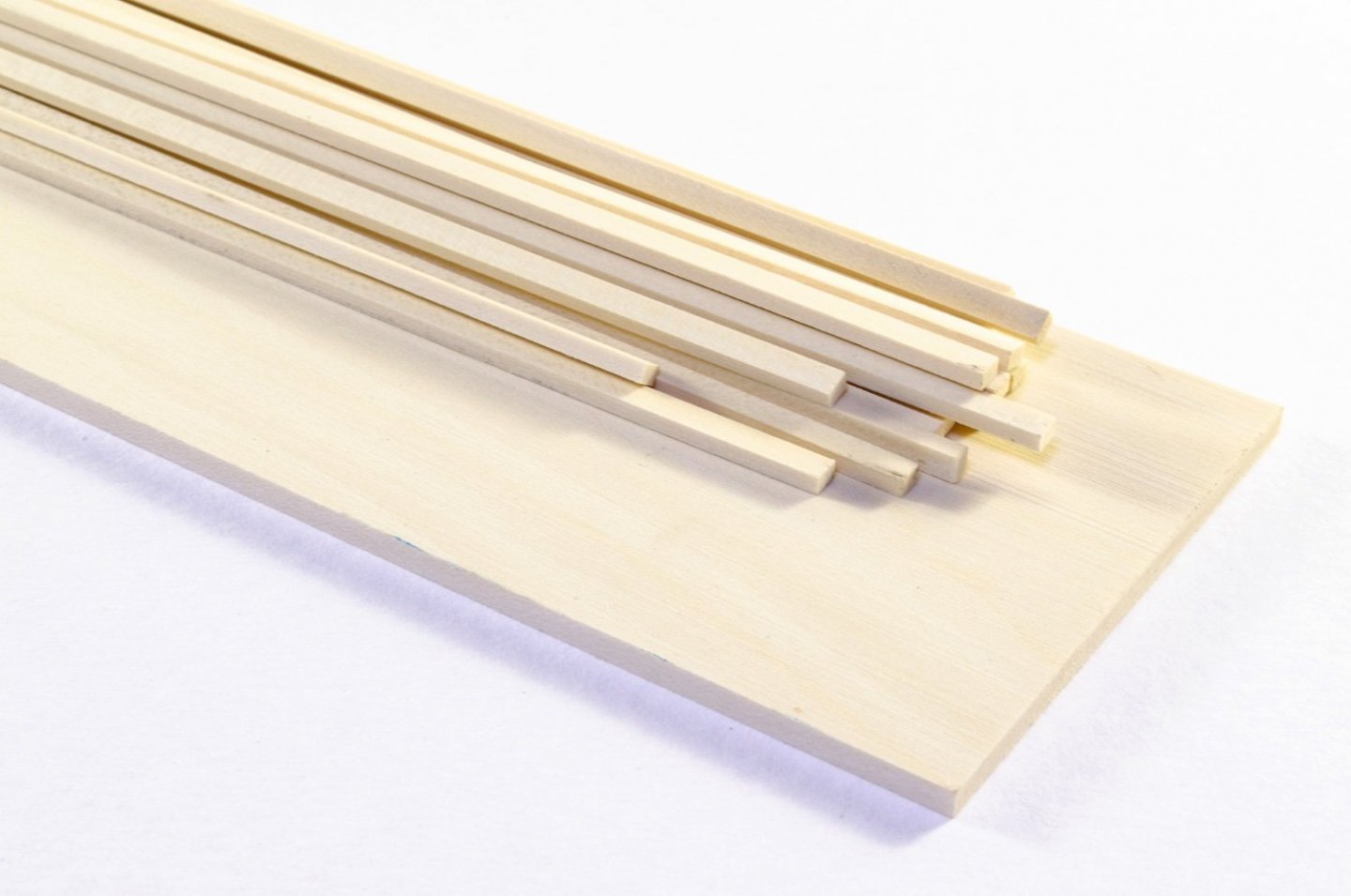
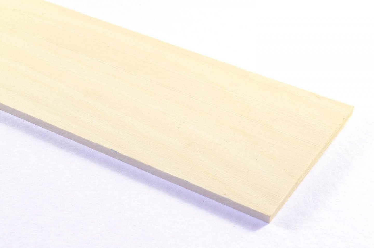
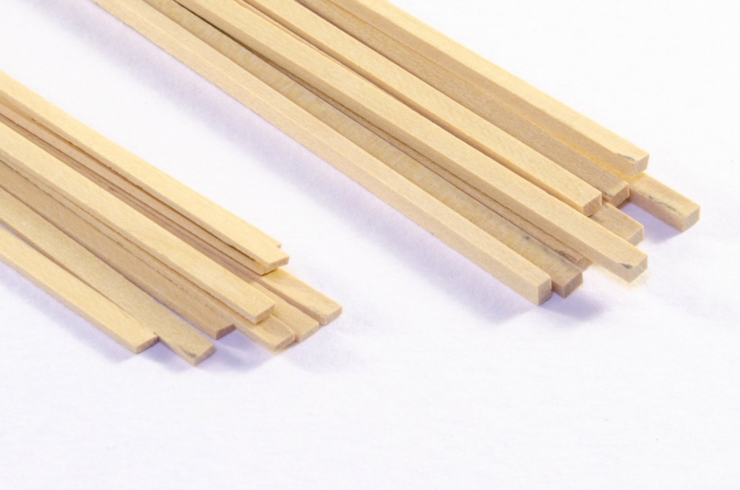
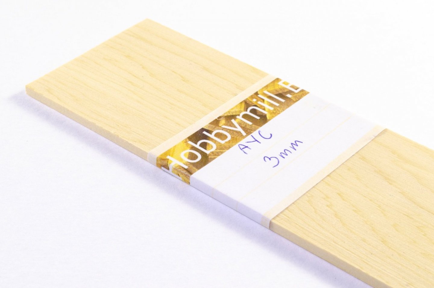
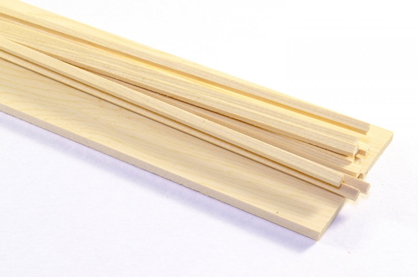
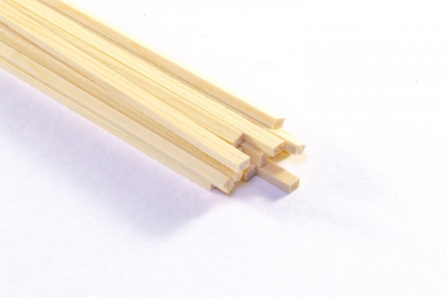
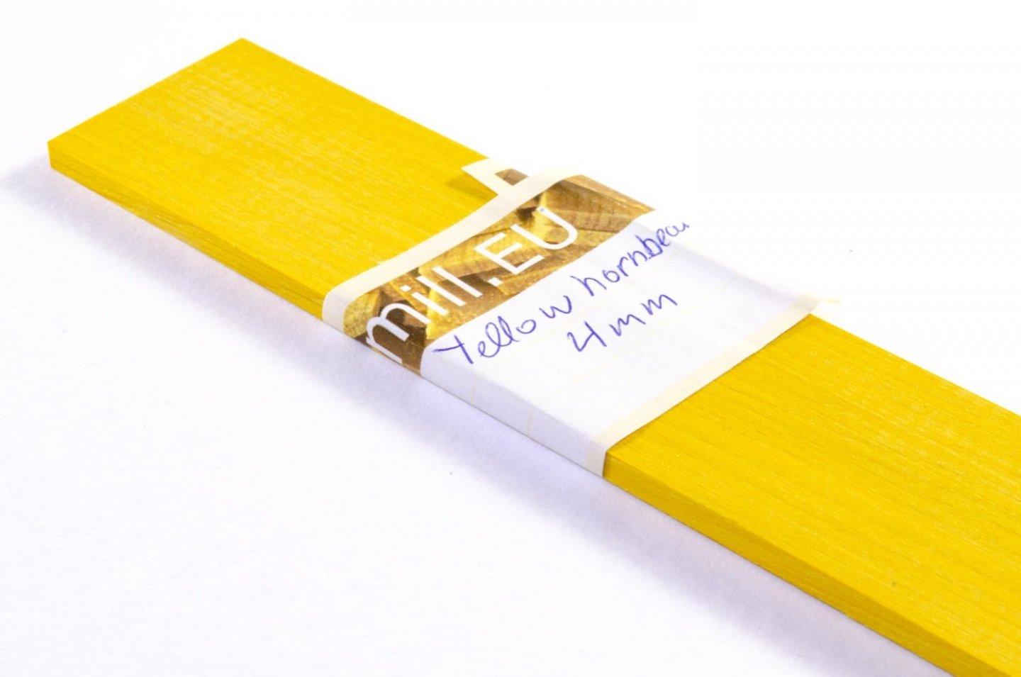
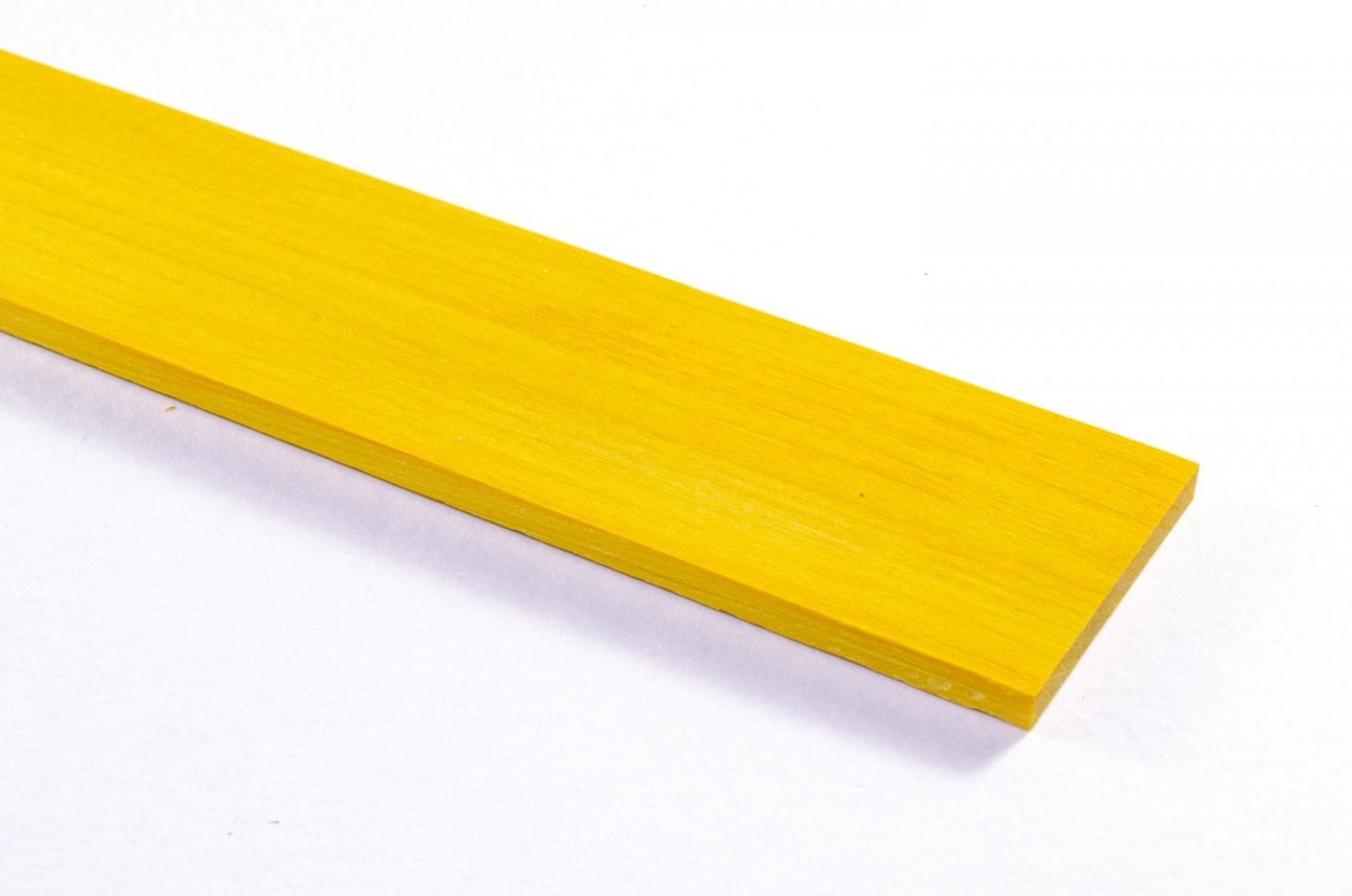
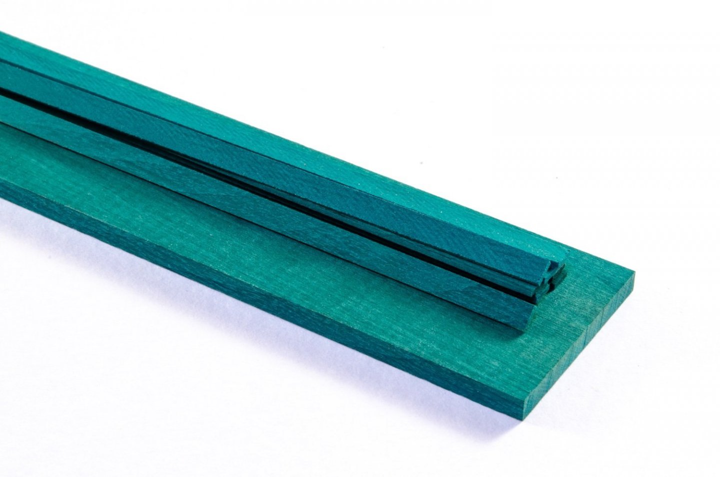
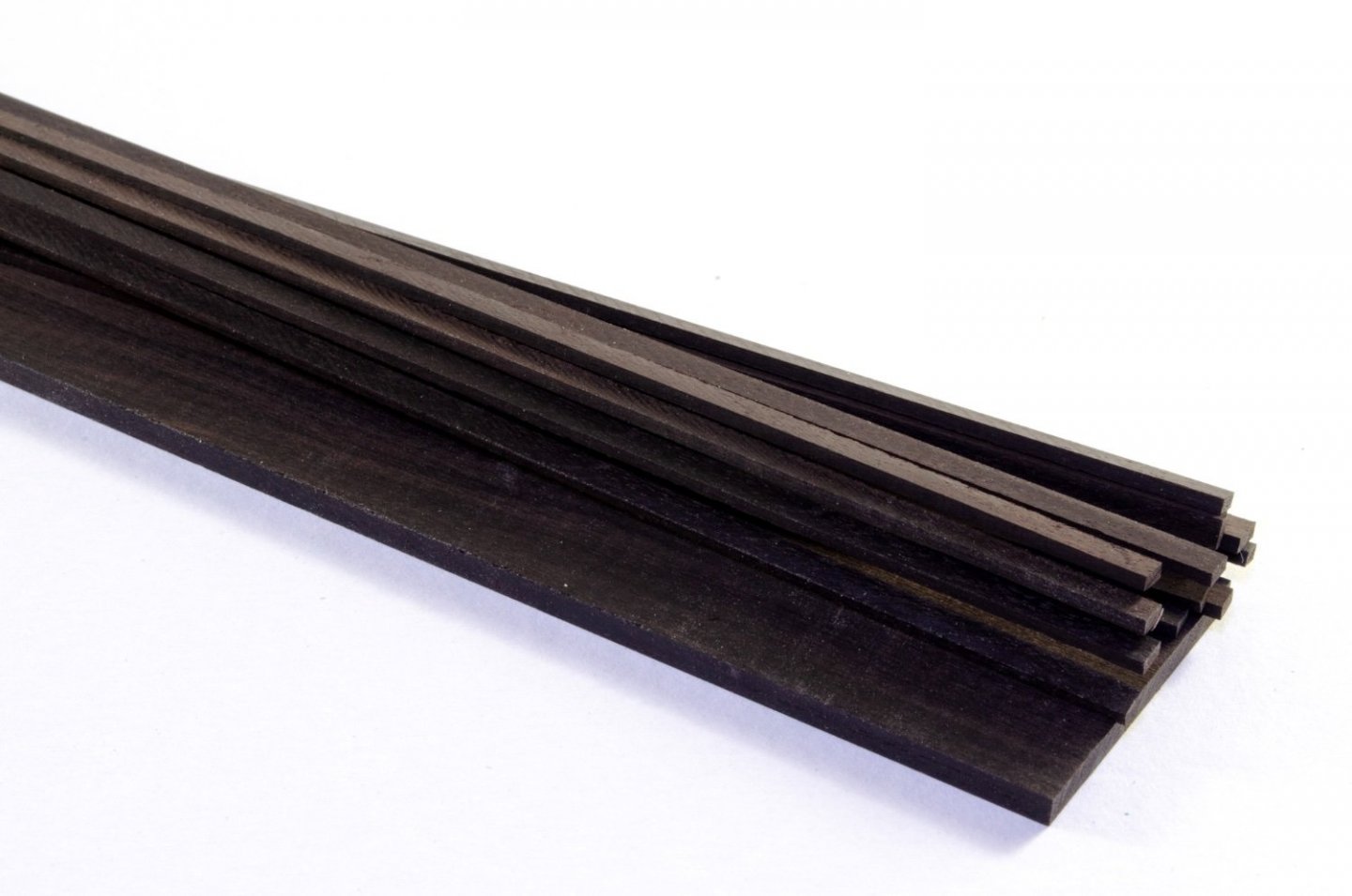
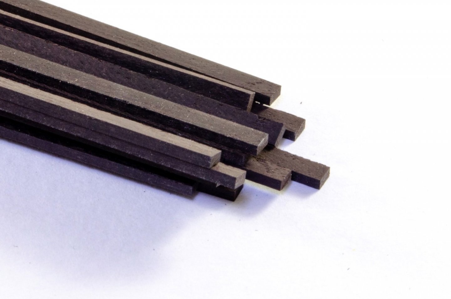
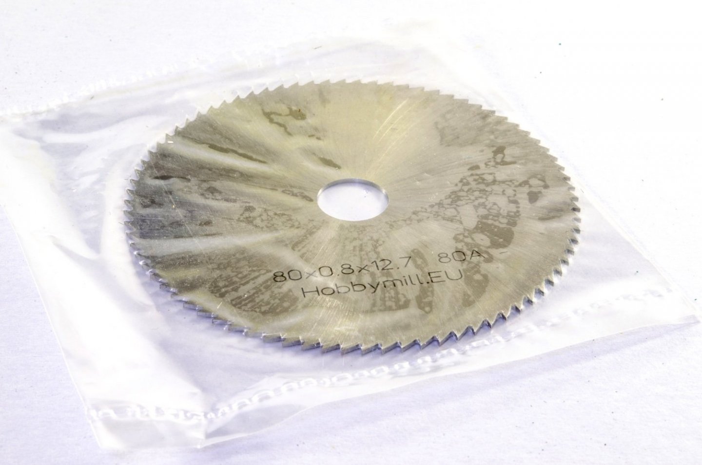
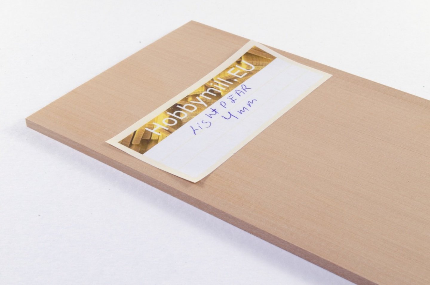
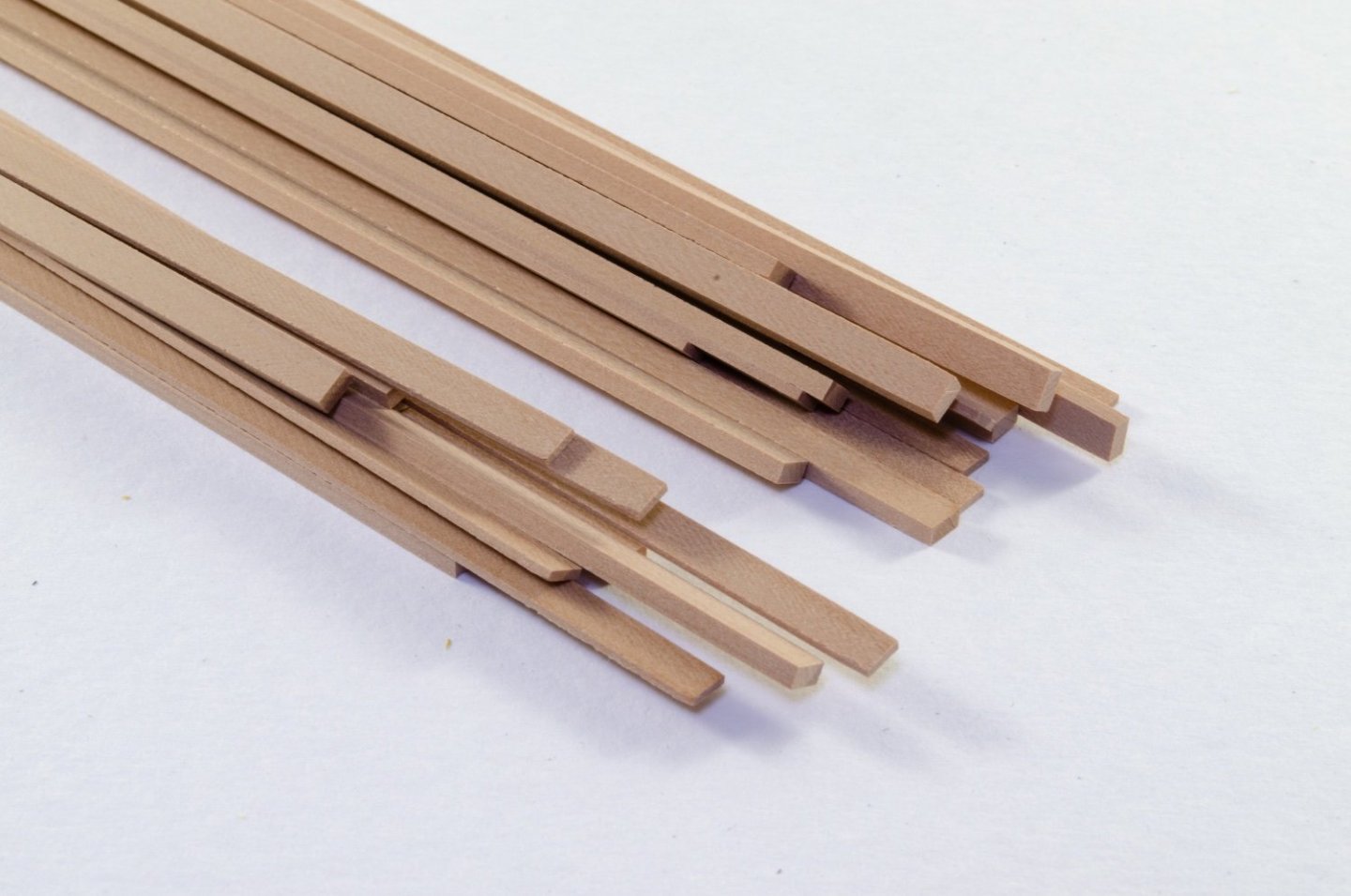
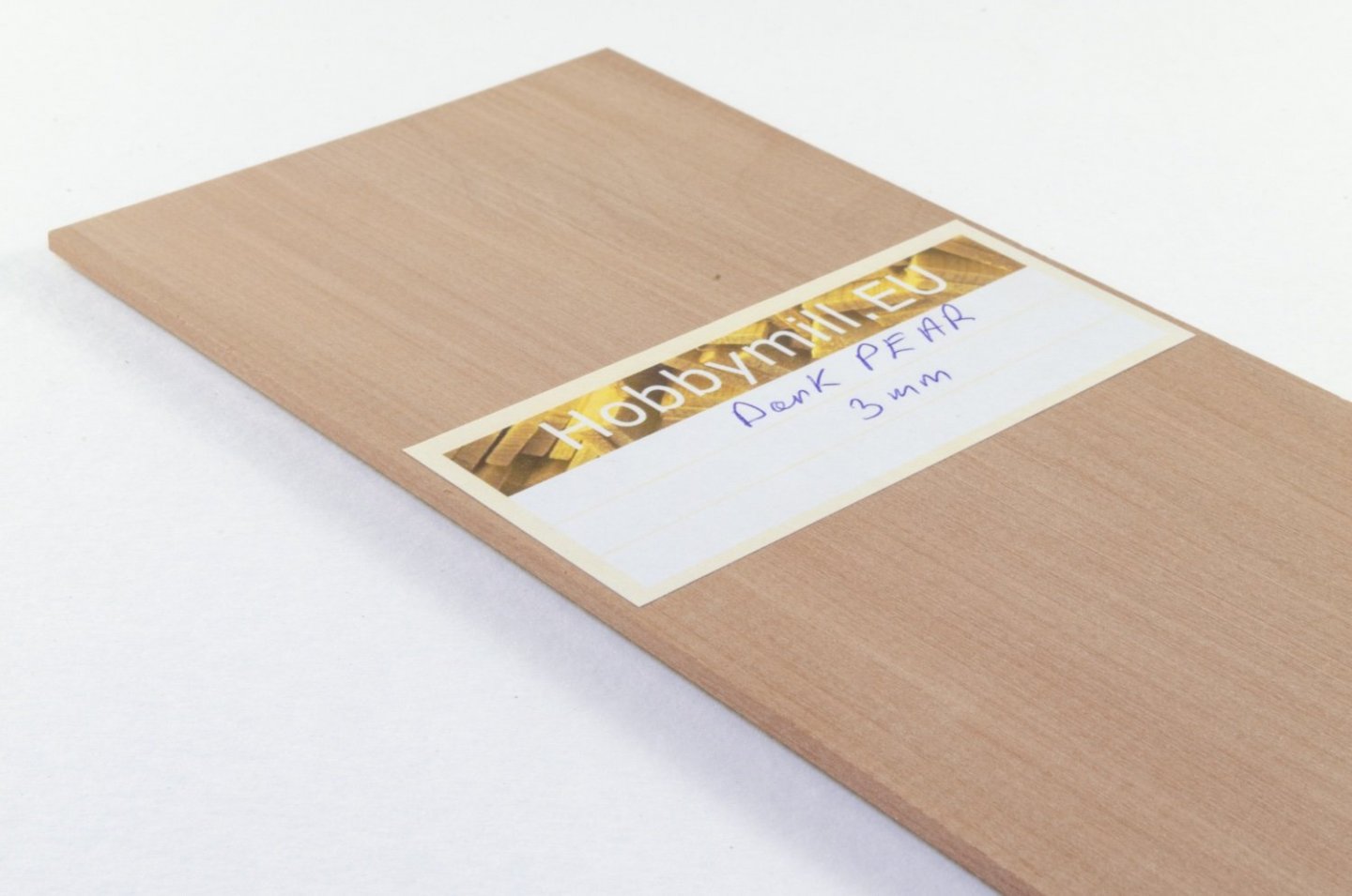
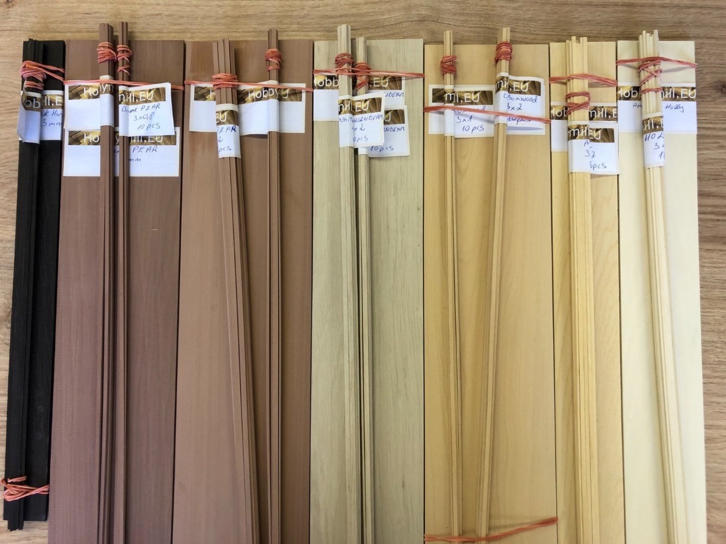
Timber - Various sheet and strip HobbyMill.EU see website for sheet and strip price HobbyMill.EU are an Estonian-based company (Tallinn), operated by a guy with a very real passion for what he does, and both my communications with him and the timber samples sent, clearly show that. The material he saws and processes is sourced from quality EU-based suppliers. Timber as a natural product, can contain colour variation, imperfections etc. and because of any small flaw that may be present on the strip, for example, I'm told that where this happens, a small number of extra strips is usually added so the customer gets exactly what they need in usable material. The same also goes for width. If you order a sheet that's 100mm wide, the chances are it will be slightly more than that, depending on the size of billet that it's being cut from. If there's 20mm (for example) width to produce 100mm wide sheet from then you will get the 120mm so as not to waste any material. Another note goes for the sides of the sheets being parallel. I have to say that mine are pretty darn good, but you may get a little variation. It really doesn't matter as long as the grain is true and the edges are nice and straight, and they are indeed that on my samples....which are taken from the general production in order to create a true reflection of material quality. All edges are nice and sharp and the ends are clean. There are some very faint machine marks in places, but I only really notice those on my photography and not really on the actual product, apart from the coloured hornbeam. In order to cut the timber, HobbyMill are using Byrnes tools etc. The timbers sent to me for this article are: White Hornbeam - 4mm sheet, 4mm x 2mm strip, 4mm x 1mm strip Black Hornbeam - 3mm sheet, 3mm x 1.5mm strip Yellow Hornbeam - 4mm sheet, 4mm x 1mm strip Green Hornbeam - 4mm sheet, 4mm x 1mm strip Alaskan Yellow Cedar - 3mm sheet, 3mm x 2mm strip Castello Boxwood - 3mm sheet, 3mm x 1mm strip, 3mm x 2mm strip American Holly - 3mm sheet, 3mm x 2mm strip Swiss Pear (Light) - 4mm sheet, 4mm x 1mm strip, 2mm x 1mm strip Swiss Pear (Dark) - 3mm sheet, 3mm x 2mm strip, 3mm x 0.8mm strip The wider sheets are 100mm wide x 500mm long, with the narrower ones being 50mm wide. coloured hornbeam was added after this photo was taken The package took around 8 days to arrive in the UK, from Estonia, via tracked mail. A rigid card box was used to pack the samples, and inside, the various sheets and strips were packed into sleeves and further protected by layers of bubblewrap film. Various strip packs were also bound with elastic too, and not so there was any deformation to the timber. Pre-caulked planks? HobbyMill also supply, to order, pre-caulked planks. You will need to enquire about those, but that would sure save some time when it comes to planking your deck! White Hornbeam This really is very nice indeed, with a very fine grain. A very nice timber for deck planking. Nothing fibrous here as the nice, tight grain makes for clean cutting and a sharp edge. A very good timber for deck planking. American Holly This is the palest of all the samples sent, and is very much creamy white in colour. The grain is almost invisible on first look too. Most definitely one of the nicest timbers I've seen. Castello Boxwood This timber is a very nice light yellow-brown in colour, and also uniform in appearance. Also a nice alternative to European box. You'll notice the very fine grain in these photos. Alaskan Yellow Cedar This is a very popular timber, and indeed, Chuck uses this on his HMS Winchelsea project. The colour of this timber is just gorgeous, imparting that very pale yellow look, and sporting a nice, tight grain. I can see why Syren favours this in their work. Yellow Hornbeam I'm told that these timbers are favoured by Russian master model shipwrights and not so common outside of that region. It's certainly vibrant and yes, the colour remains when you cut it. I'm told this is due to the dye process presumably done in a vacuum so that the dye penetrates deeply. Hornbeam is finely grained, so of course you have that property transfer to a coloured timber. Green Hornbeam Black Hornbeam One thing I couldn't capture here is how nice this timber is. The grain looks more prominent on these photos, but it's actually not like this in reality. It's also darker than shown here and more even looking. Black hornbeam is a very good substitute for ebony. It's easier to cut, the dust won't be as nasty as ebony, it's easier to bend, and finally, it will be easier to glue. Swiss Pear (Light) Pear can vary a little in shade, and HobbyMill provide this in both light and dark types. You can see the difference from my photos, from a pale pinkish timber to a darker and more slightly grey look. Perhaps grey isn't the colour I'm looking for, but my eye sees that very slight tint in an overall darker pink tone. All pear is very fine in grain with very little in the way of any flaw in the sheets. Swiss Pear (Dark) Also available - Cutting discs for Byrnes saws These aren't to be found on the HobbyMill.EU website, but if you enquire, you can order them for around €17 each. These are Czech made and definitely help those at this side of the pond where getting the original Byrnes blades can be a costly process due to import taxes etc. These are the same blades that are used to cut the timbers sold by HobbyMill. I have to say that it's been a pleasure dealing with HobbyMill.EU, and I'm sure @Wahka_est will be more than happy to answer any questions you have regarding his timbers and availability etc. Again, it's nice to deal with someone so passionate about their product. This really does seem to be a labour of love for him, and the product itself is definitely a testimony to his very exacting standards. If you're in the need of something for a project, definitely consider this company. I don't think you'll be at all disappointed.


-
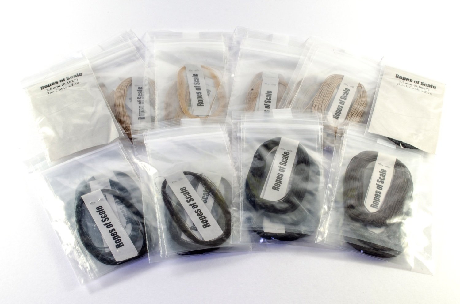
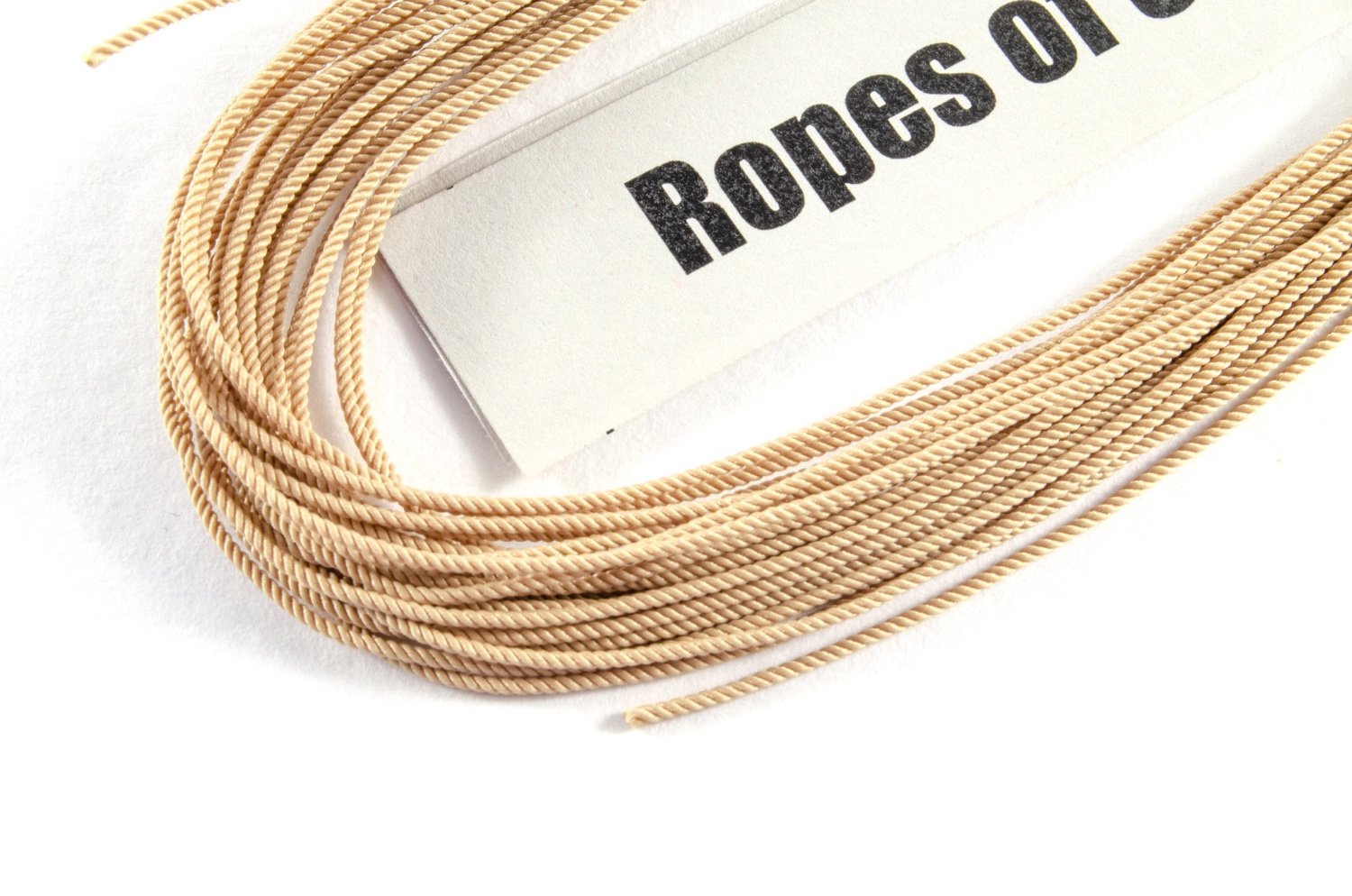
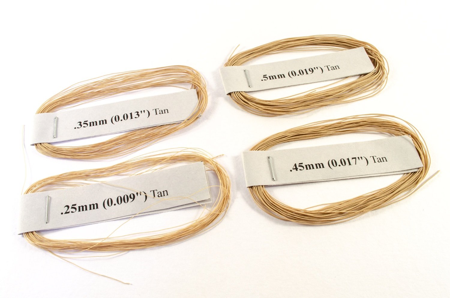
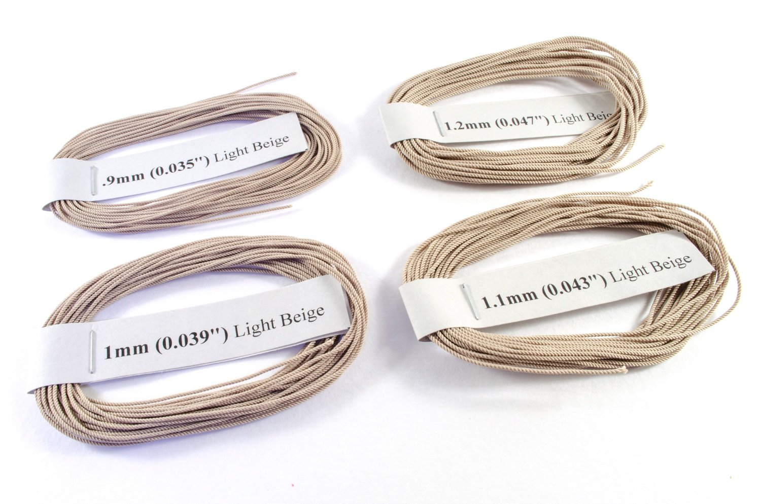
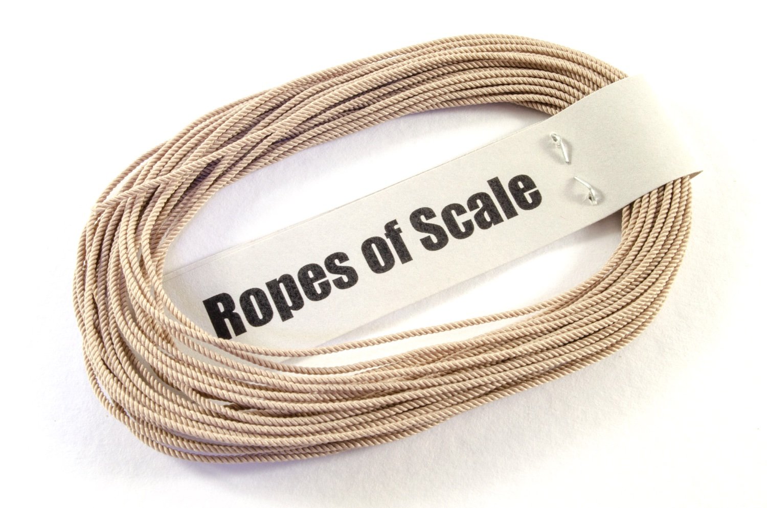
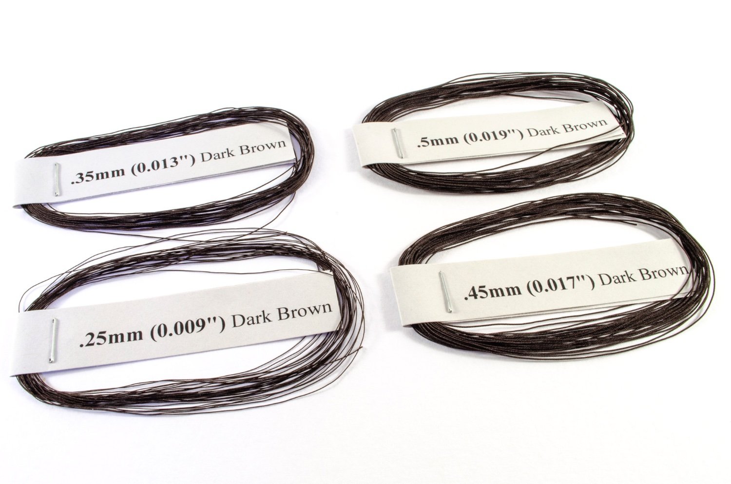
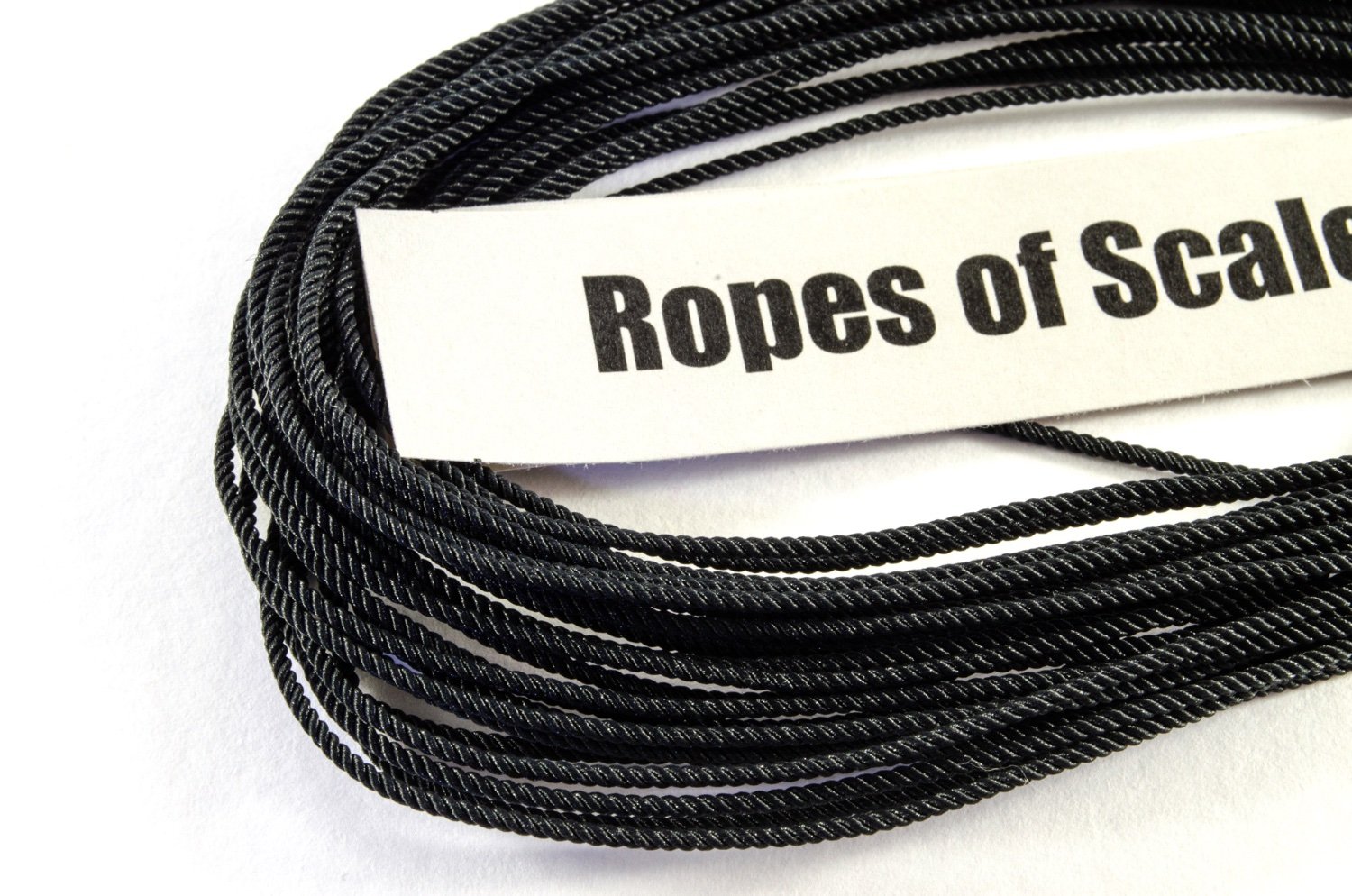
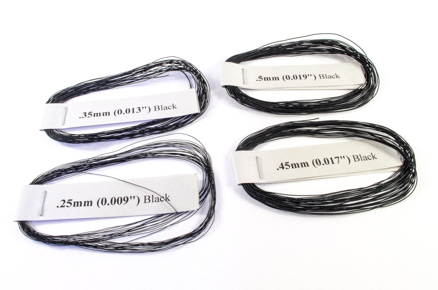
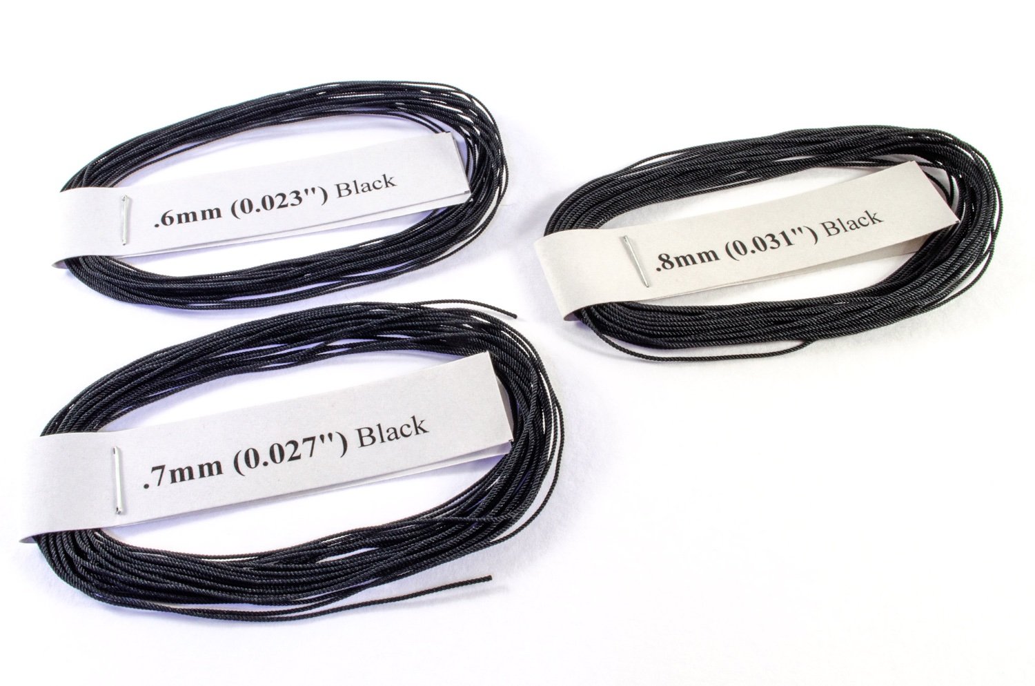
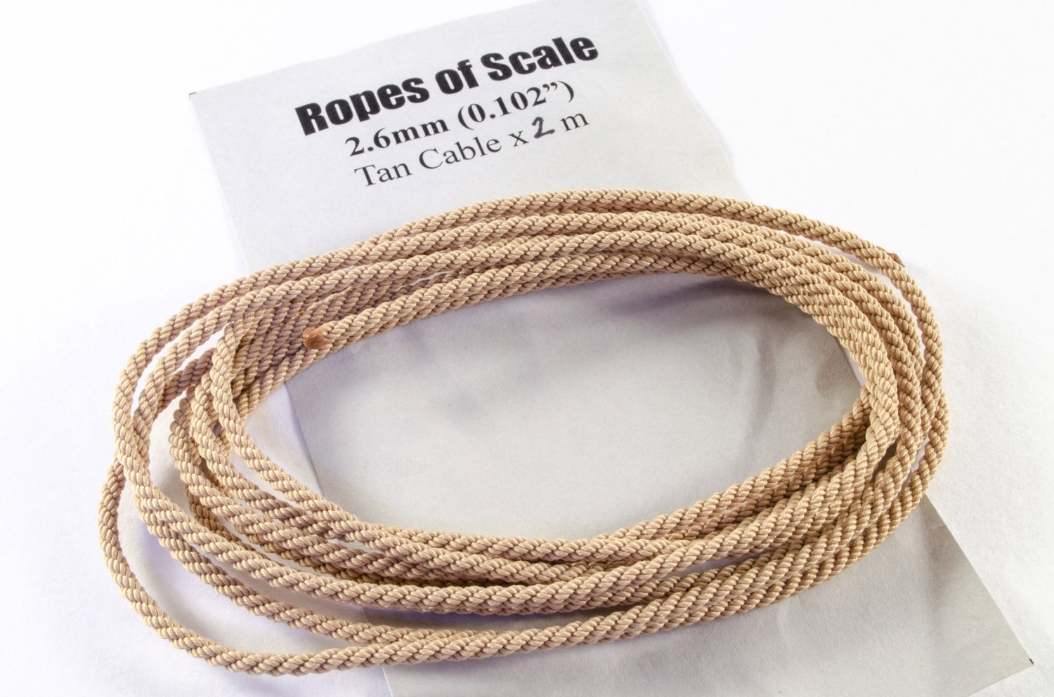
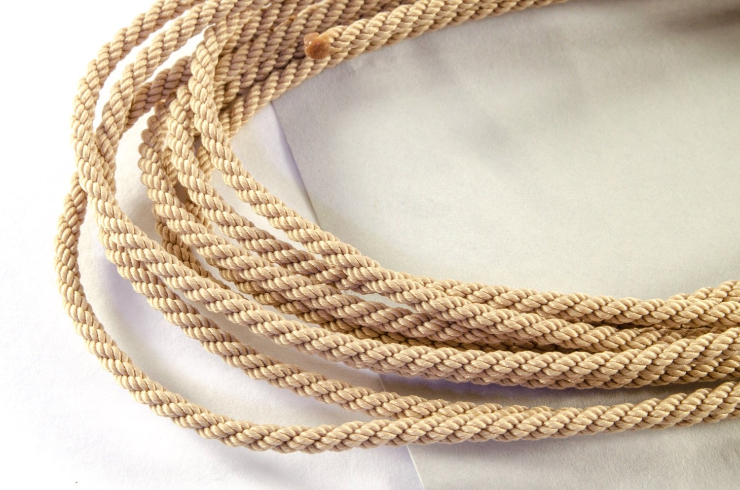
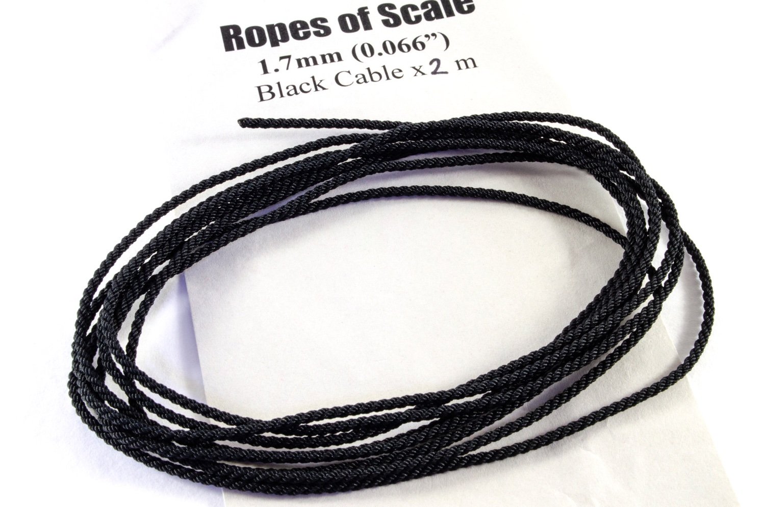
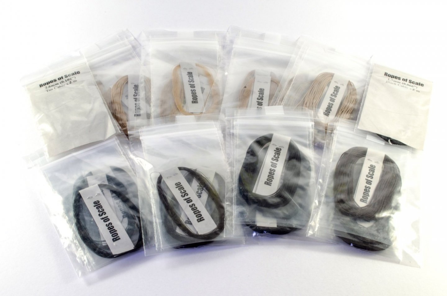
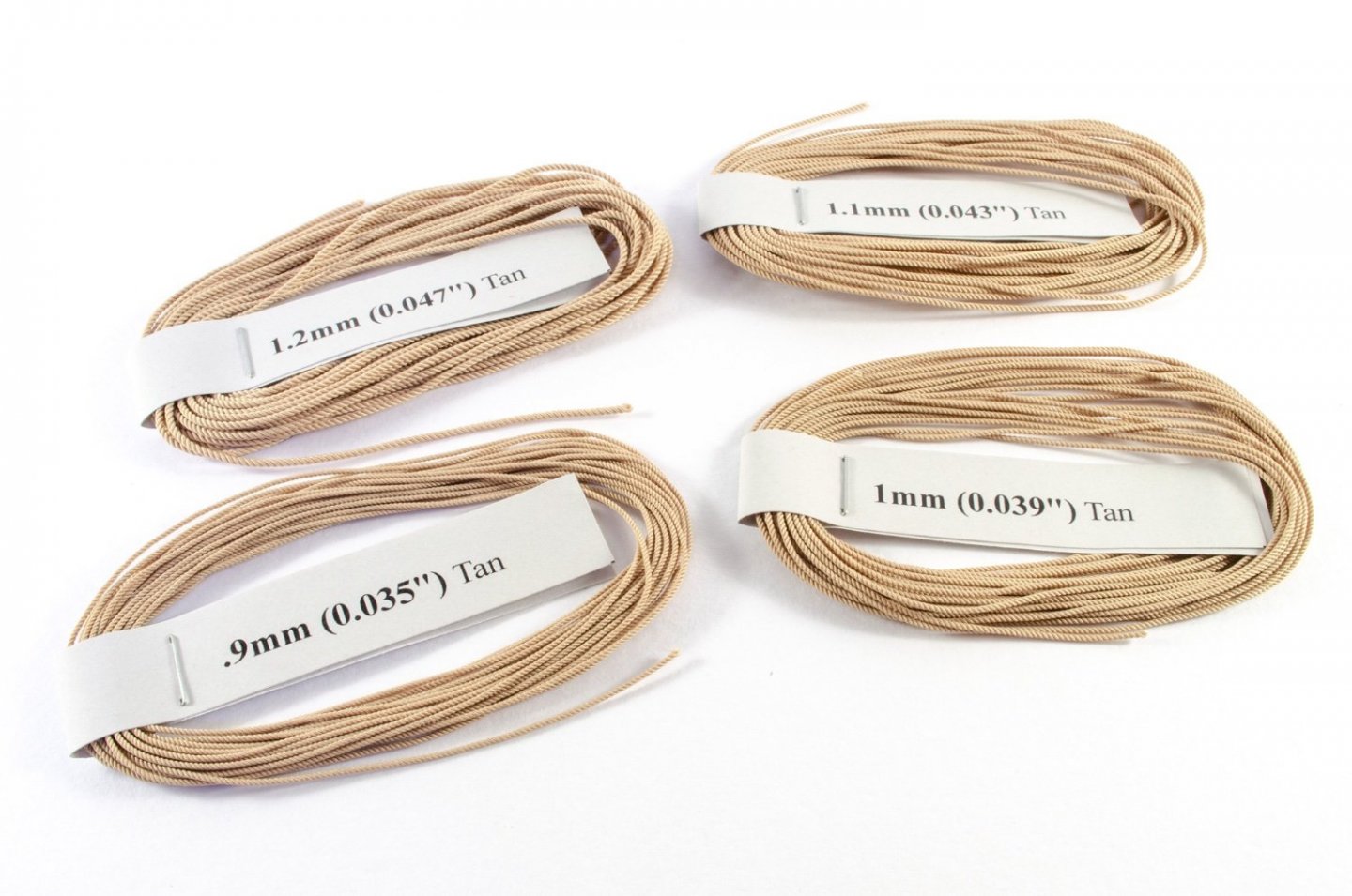
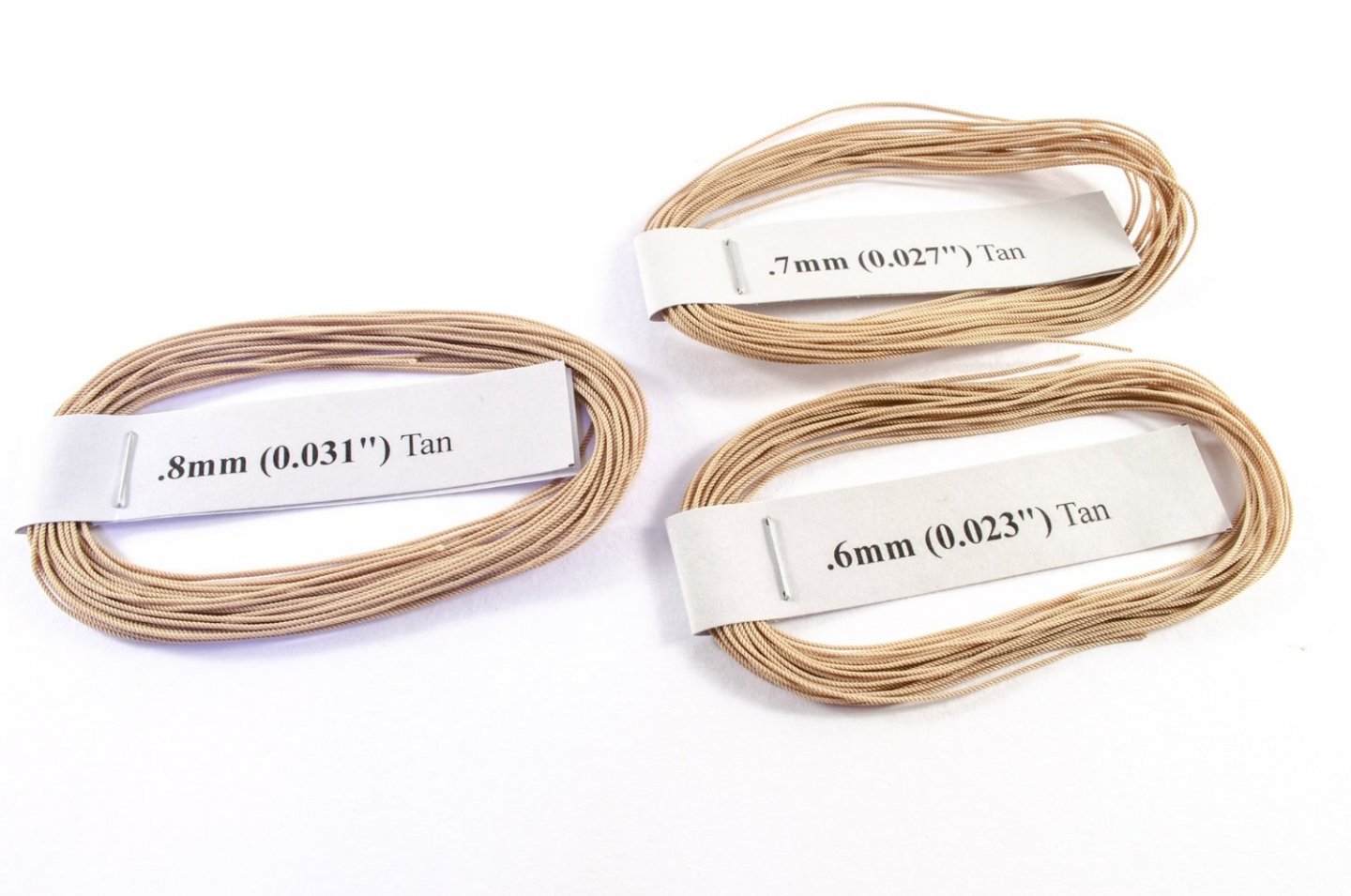
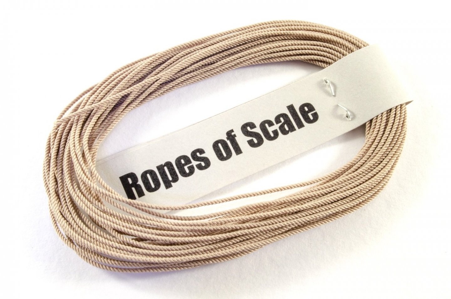
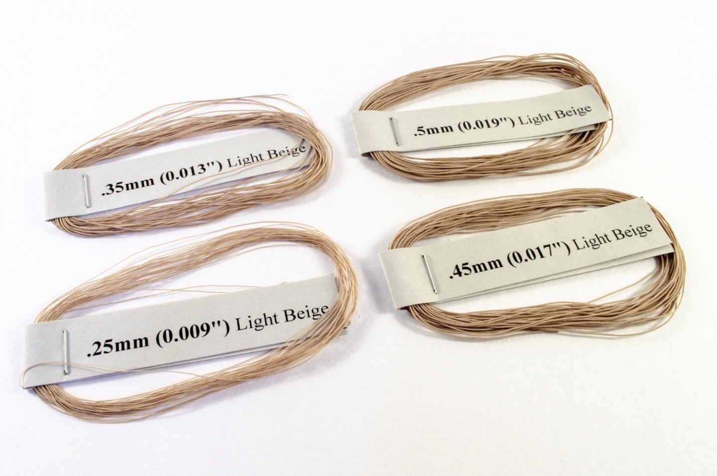
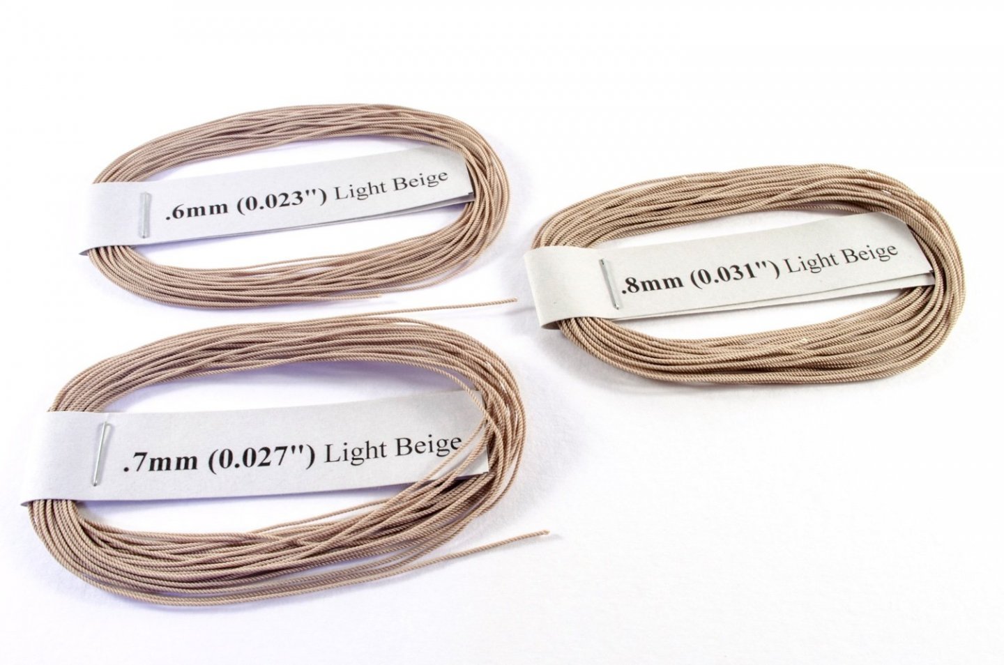
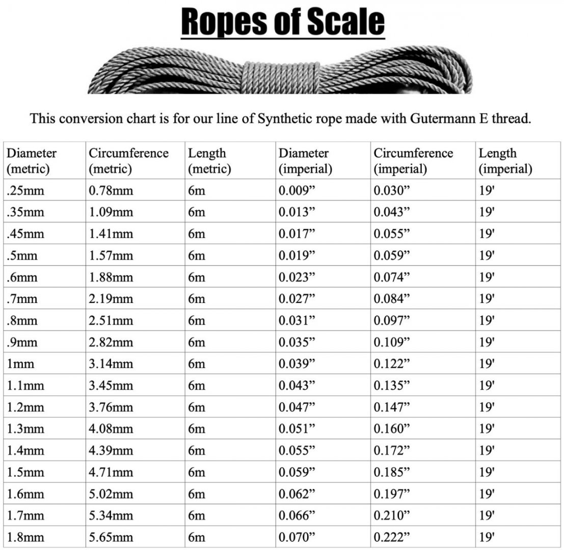
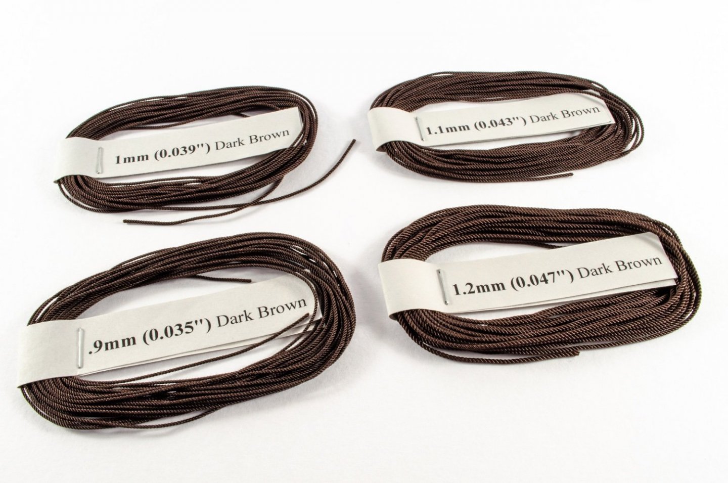
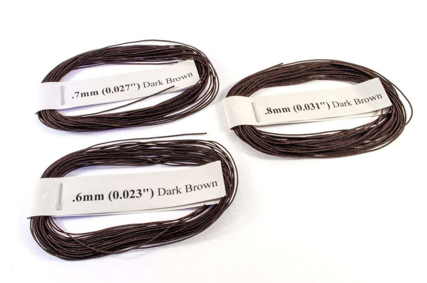
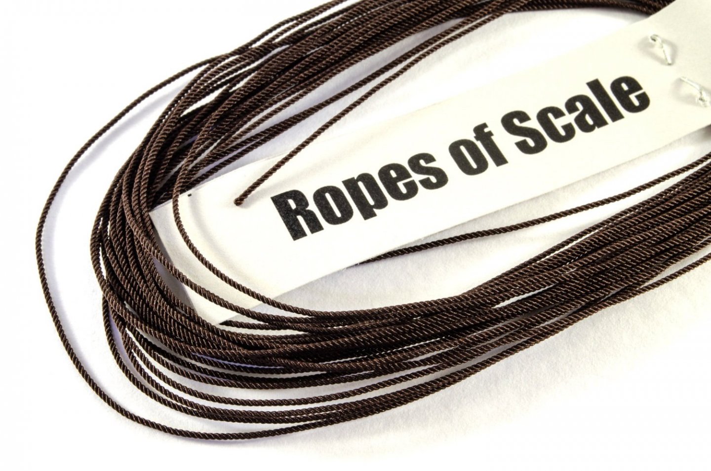
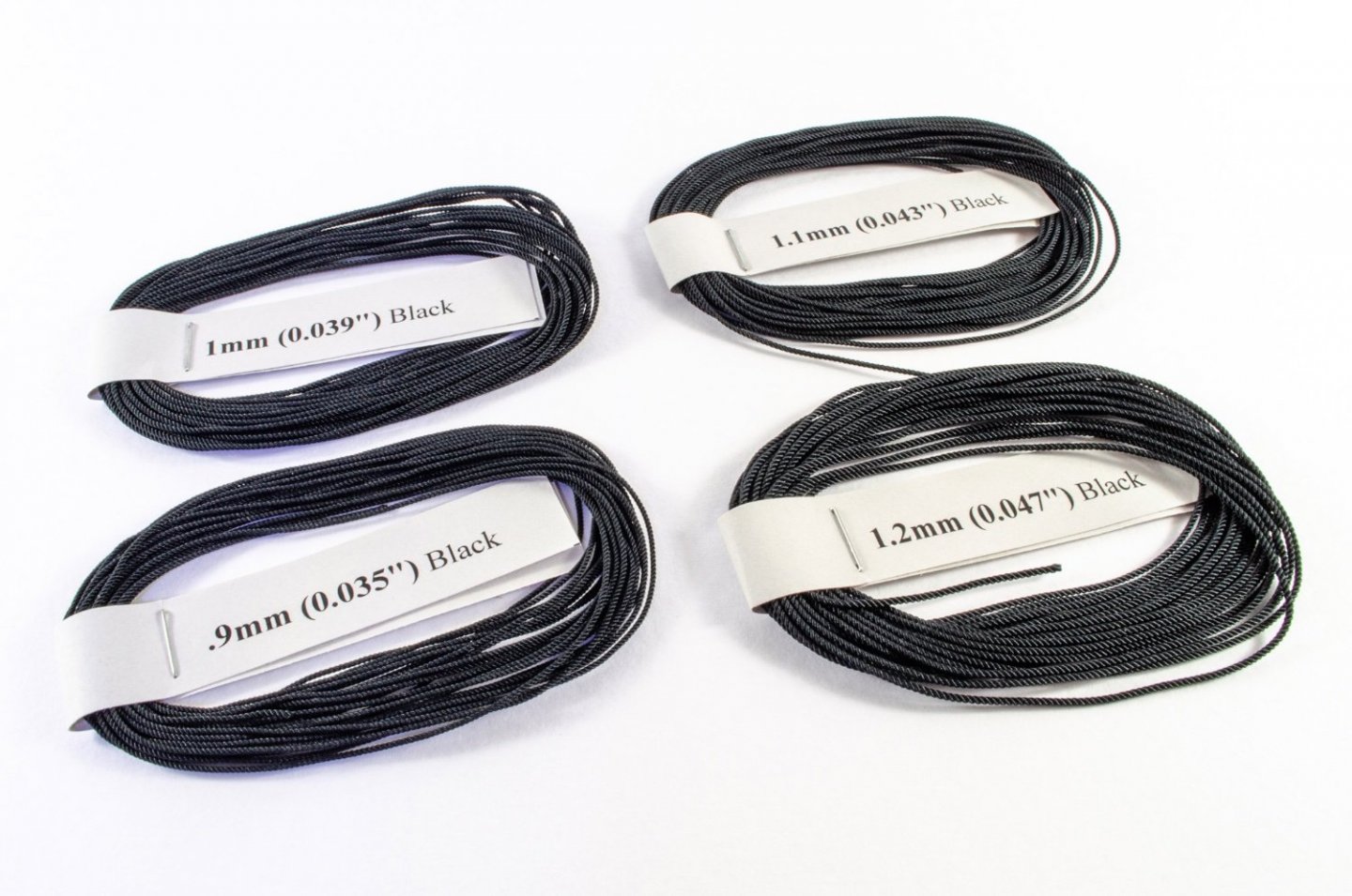
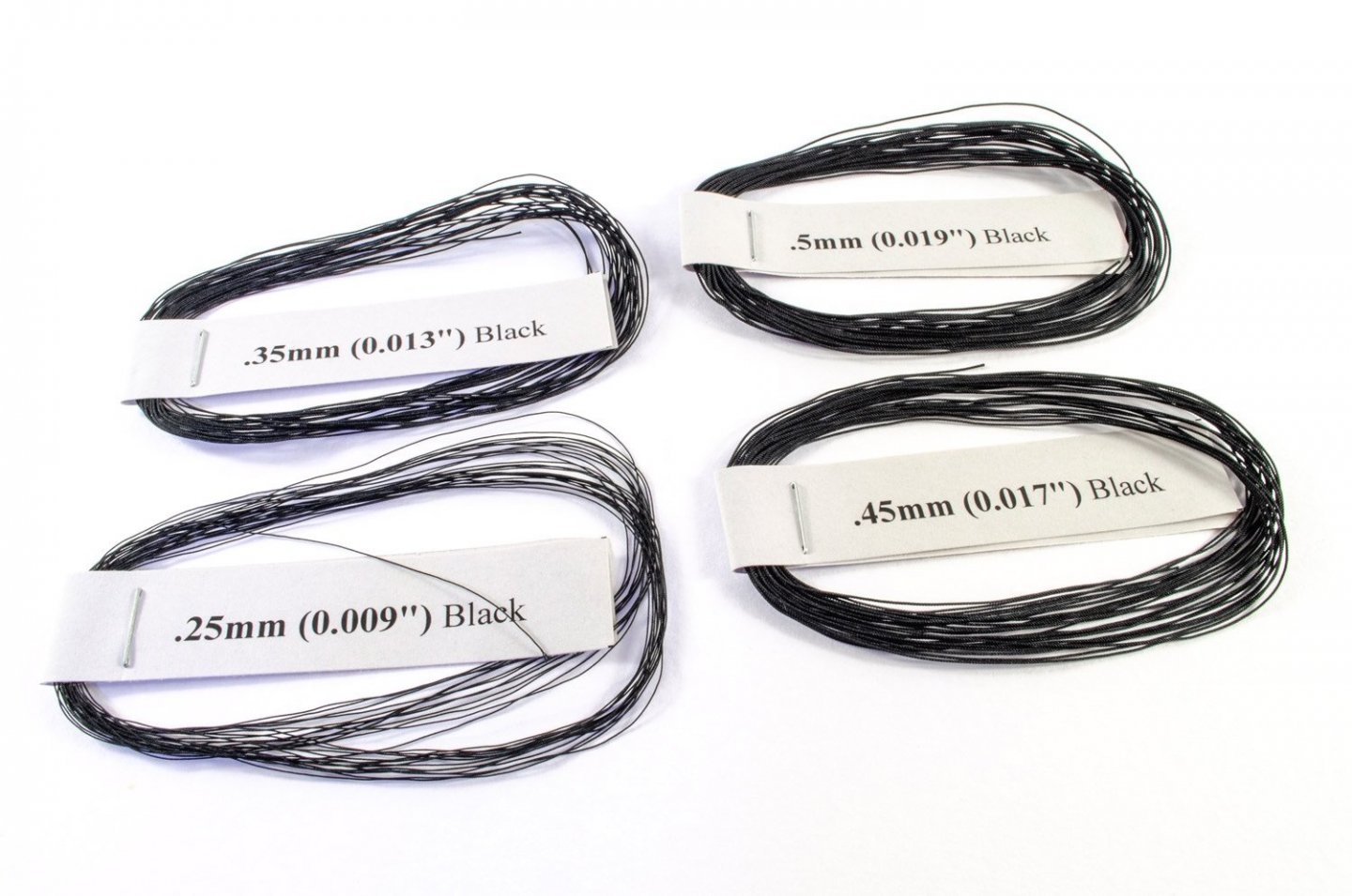
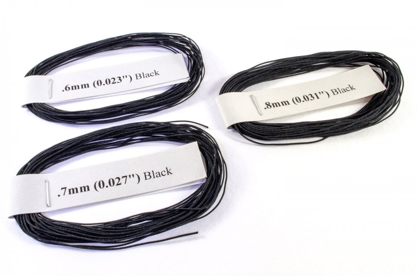
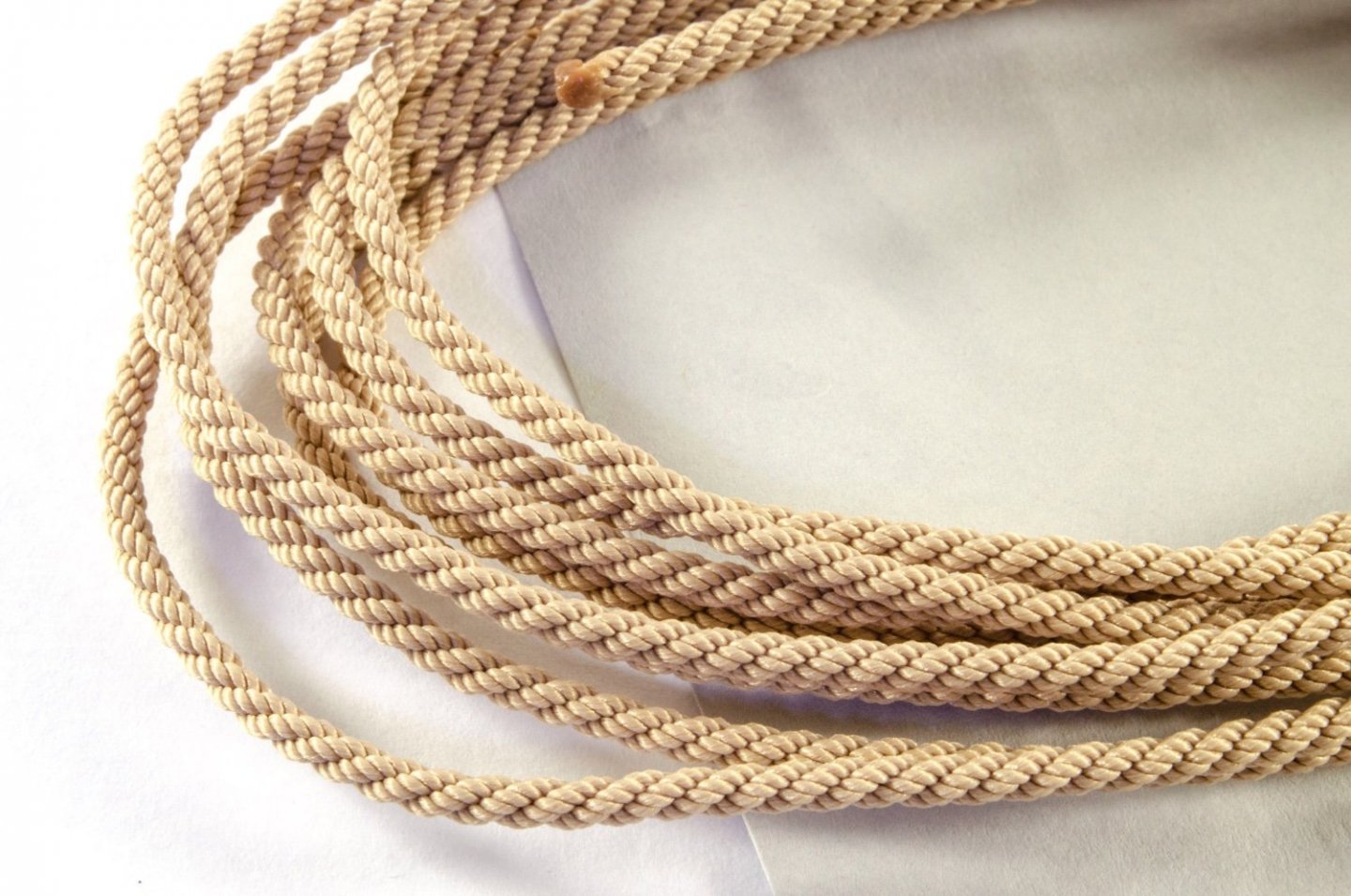
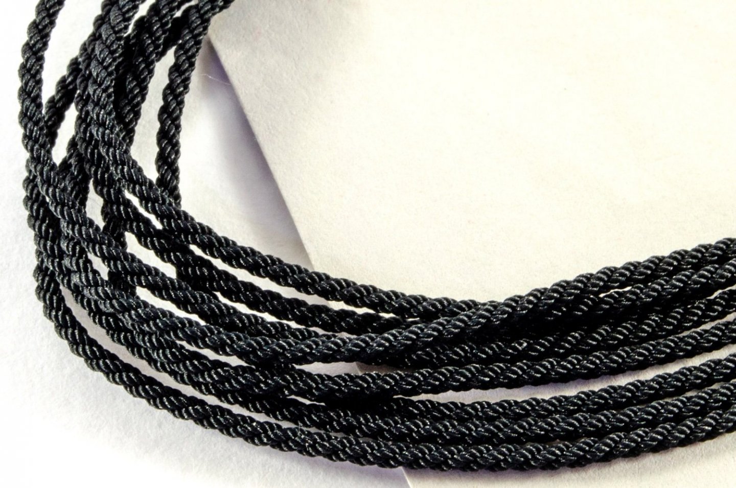
Rope and cable - various sizes Ropes of Scale Check website for specific price/size Afternoon all, Ben from Ropes of Scale recently sent me a package of samples from his synthetic range of rope, and also a couple of of his rope-laid cables. Shipping from Canada took around 2 weeks, which I don't think is too bad in this current climate, and the pack came in a thick, protective Jiffy-bag, unmolested by the ravages of the various postal services involved! Inside the pack were samples of rope in the following sizes: 0.25mm (0.009") x 6 metres 0.35mm (0.013") x 6 metres 0.45mm (0.017") x 6 metres 0.5mm (0.019") x 6 metres 0.6mm (0.023") x 6 metres 0.7mm (0.027") x 6 metres 0.8mm (0.031") x 6 metres 0.9mm (0.035") x 6 metres 1.0mm (0.039") x 6 metres 1.1mm (0.043") x 6 metres 1.2mm (0.047") x 6 metres These sizes were all individually bagged into zip-lock wallets and supplied in nicely wrapped loops with a 'Ropes of Scale' label applied to stop the loops unravelling. All of the above sizes were supplied in Tan, Light Beige, Dark Brown, and Black. As well as the supplied sizes, Ropes of Scale also creates these in 1.3mm thru to 1.8mm, currently. Also included in the pack were two samples of cable-laid rope. These are: 2.6mm (0.102") x 2 metres - Tan 1.7mm (0.066") x 2 metres - Black All rope is right-hand laid (left-hand laid is denoted by an 'L' on the label), and very much covers the bases that a modeller would need for colour options. These cables are synthetic, although you can get them in cotton. For these synthetic ropes, Ropes of Scale use Gutermann E thread which is totally free from any of that annoying fuzz that sometimes accompanies the rigging process. According to their website, the ropes are also been heat treated to stop it unravelling when cut, although they do still note that a little CA on a rope end may be needed to thread them through your favourite rigging blocks. Tan The colours tend to cover all the required bases with two options for both running and standing rig. When it comes to standing rig, I would personally lean towards the dark brown as it perhaps more closely represents a tarred line than black, but many folk still prefer black, so that option is also there for you. Light Beige Dark Brown Perhaps the best solution for representing tarred standing rig. Black Probably the favourite and most widely used colour for standing rig. Rope-laid Cable These are supplied here in 2m lengths. I've been using some Gutermann rigging cord over the last year or so with my work on Vanguard Models' kits, and I have to say that I very much favour the brand as it's trouble-free when in use and doesn't have the common tendency to snag while working either, so these will be an absolute joy to work with. Manipulating the rope also doesn't result in the threads separating too. This is the first professional grade of rope that I've experienced in this format, and I have to say that I do like it very much indeed. I can also tell you that the forthcoming 1:64 HMS Indefatigable kit from Vanguard Models, will also feature hawse/cable and mast stays supplied by Ropes of Scale, so that is a very exciting development! Ropes of Scale are a sponsor of Model Ship World. If you're in need of some amazing quality, fuzz-free rope that is going to have the exact scale fidelity you require for your build, you certainly won't go wrong with any of Ben's products. They are doubtless made with passion and dedication, and you can clearly see his attention to detail in every single packet.


-
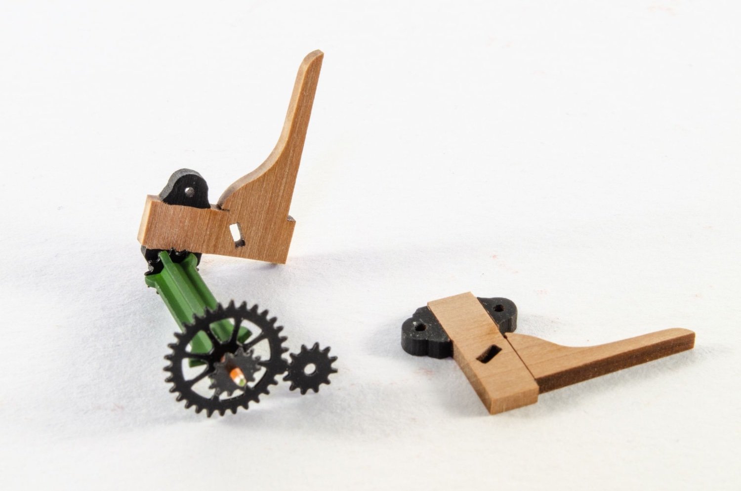
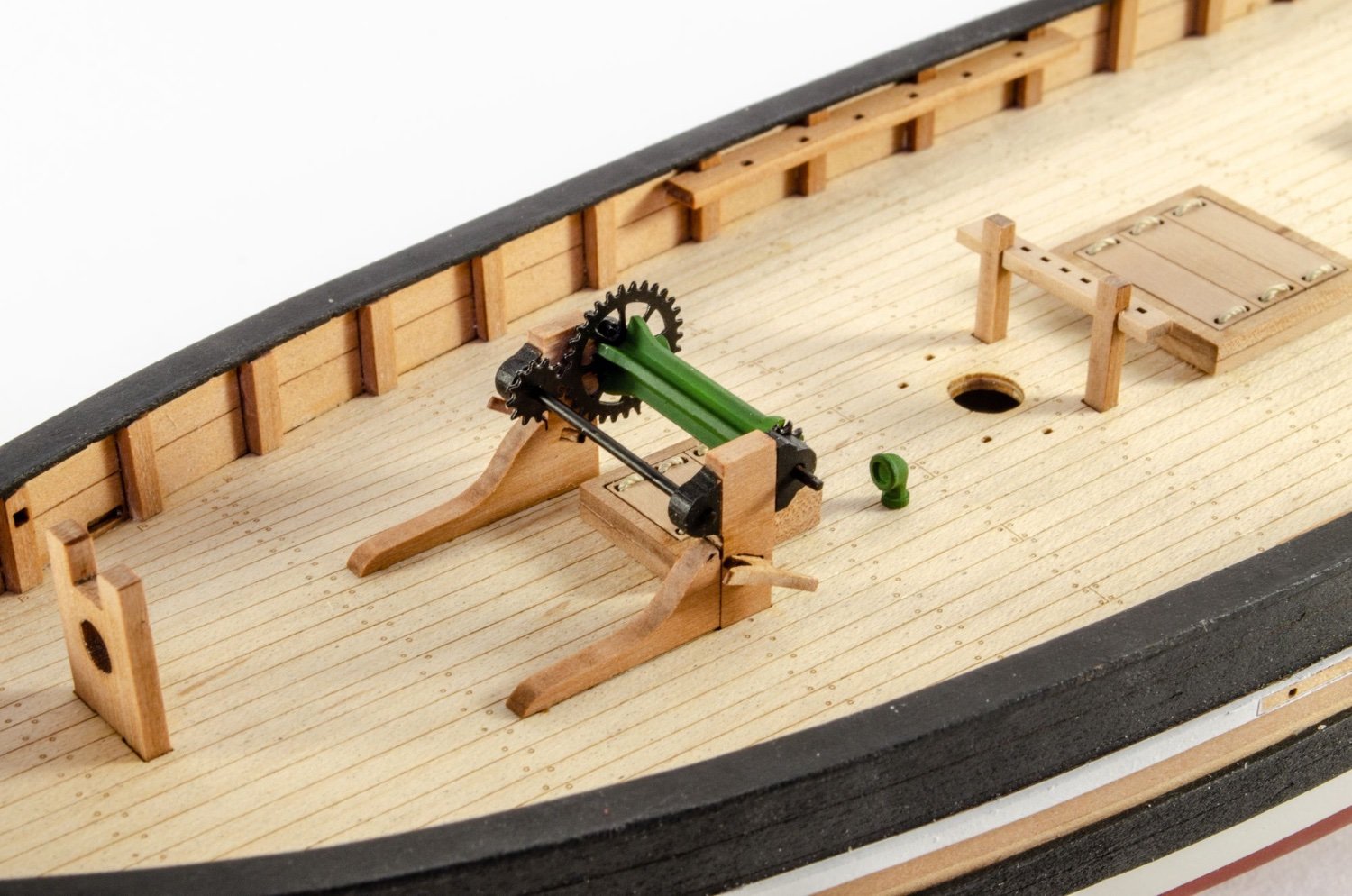
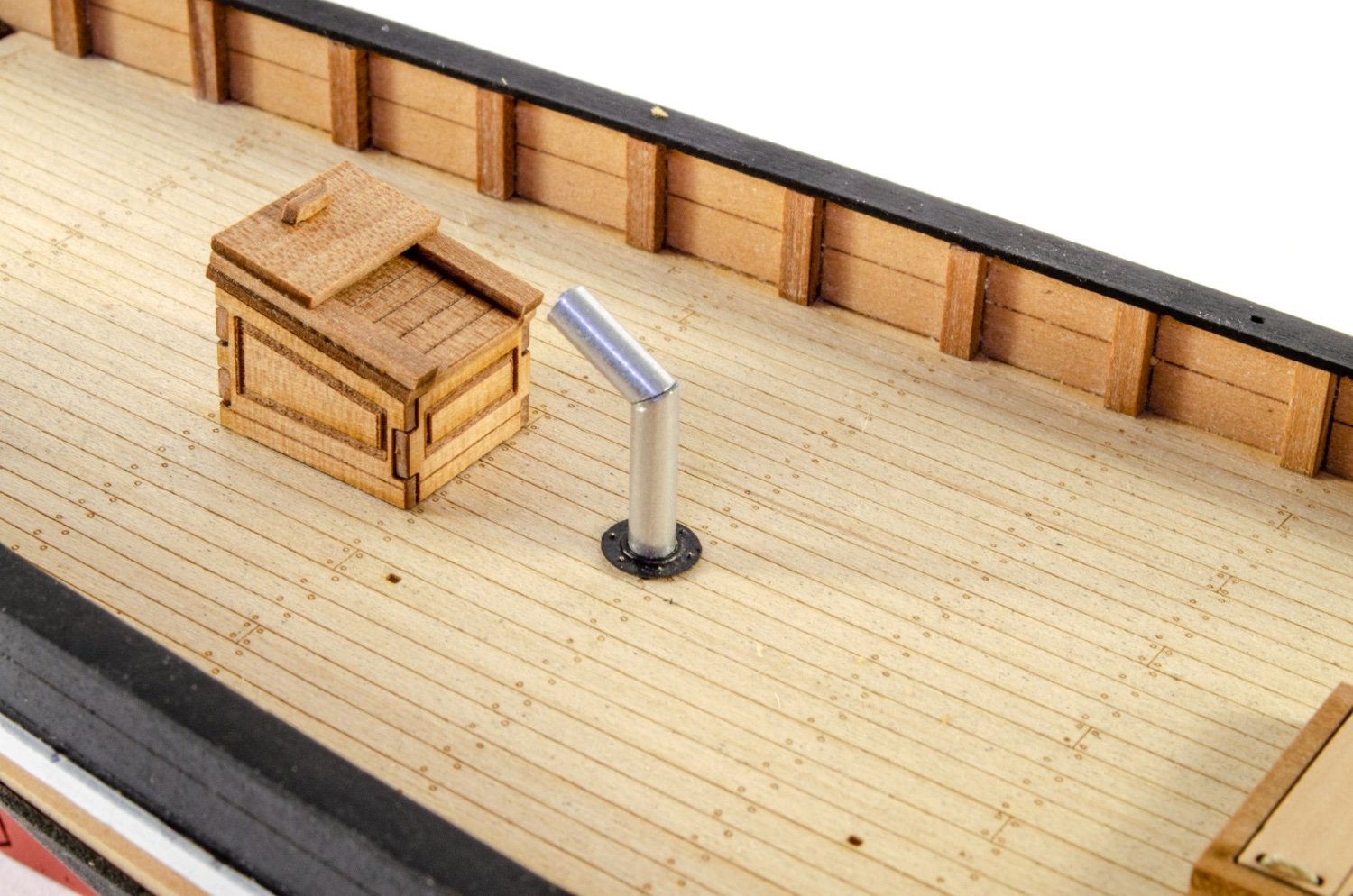
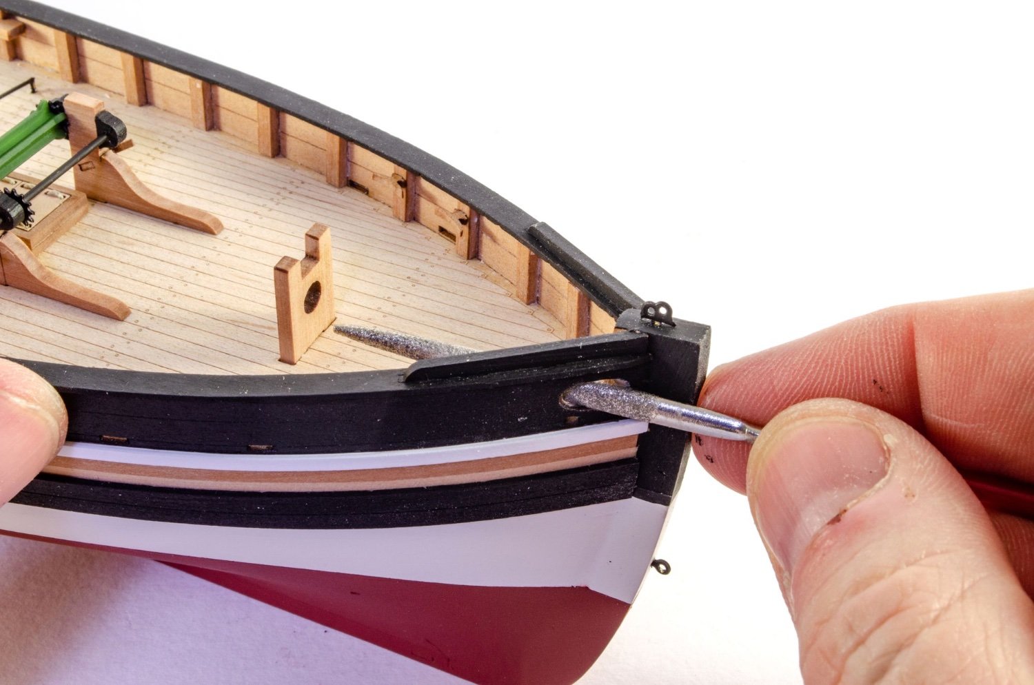
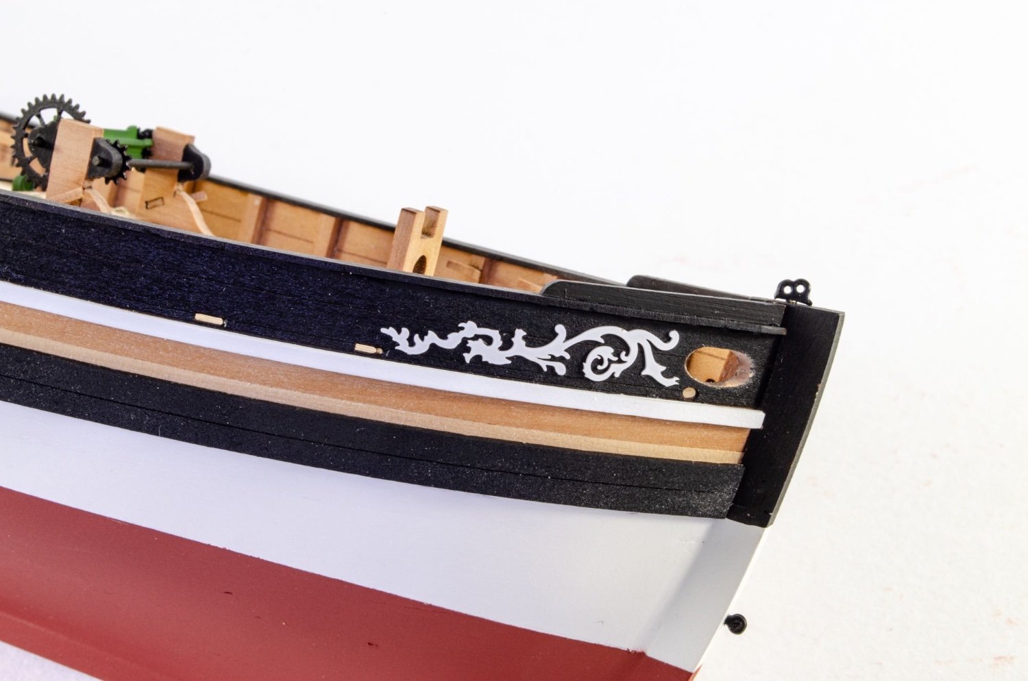
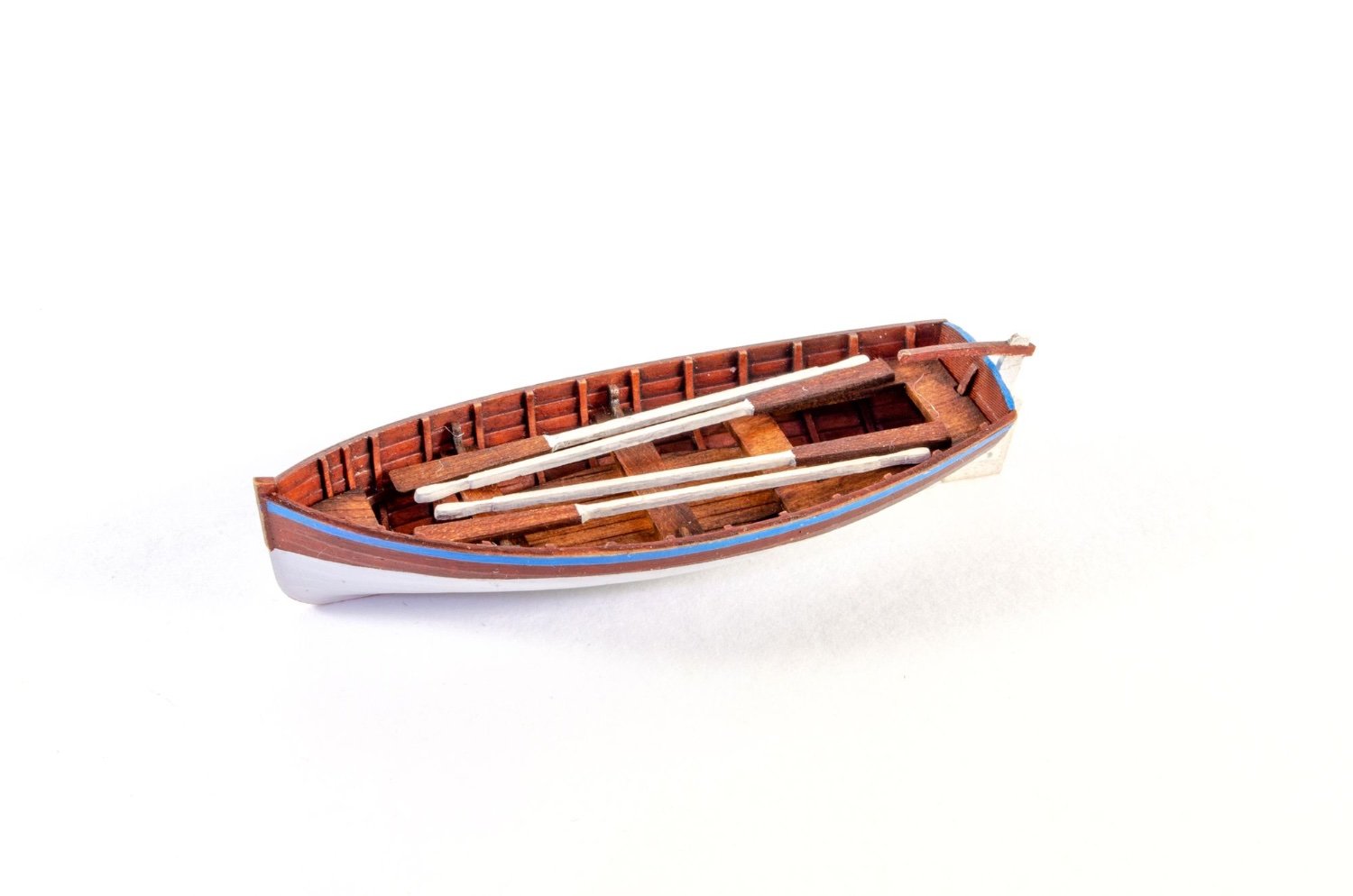
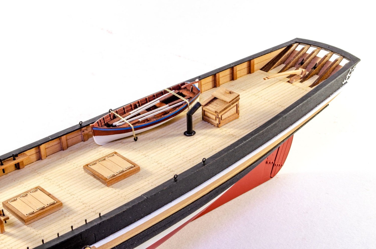
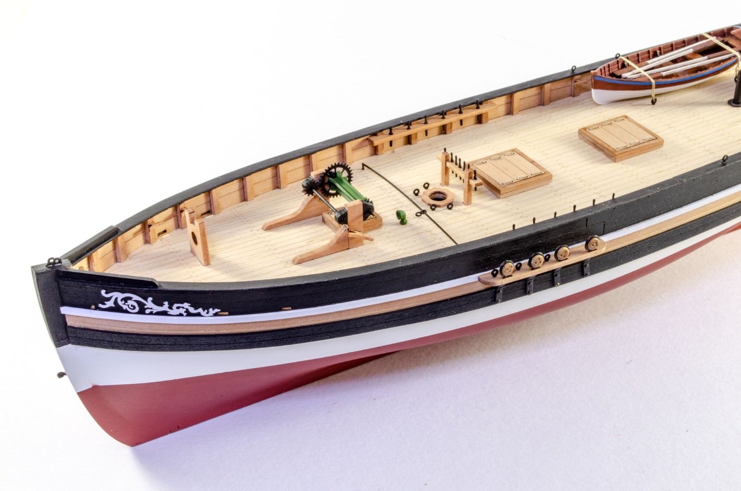
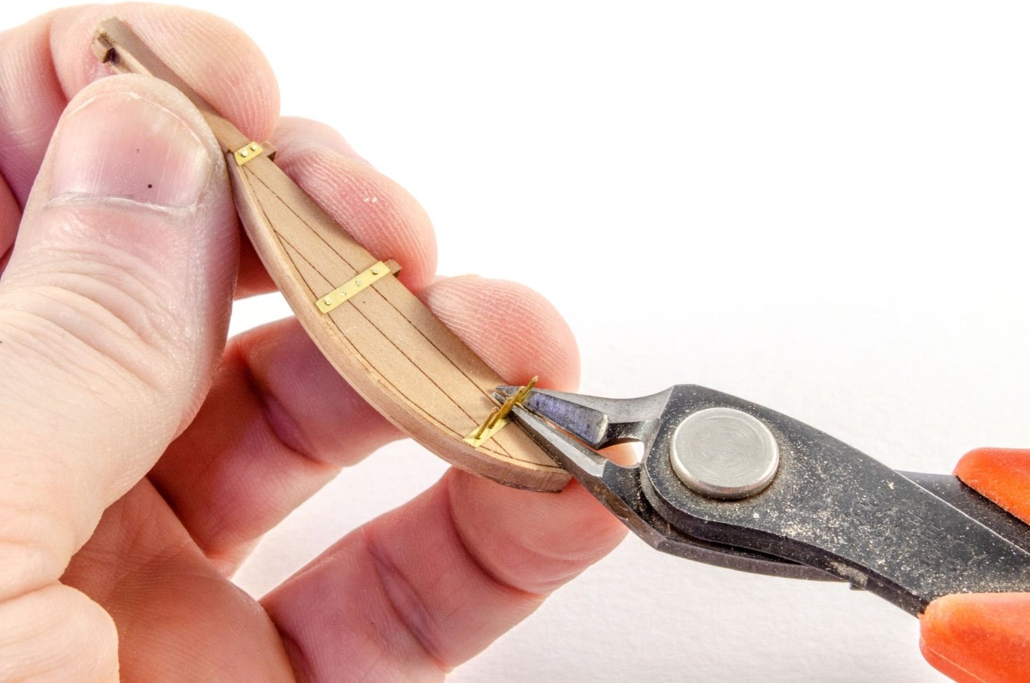
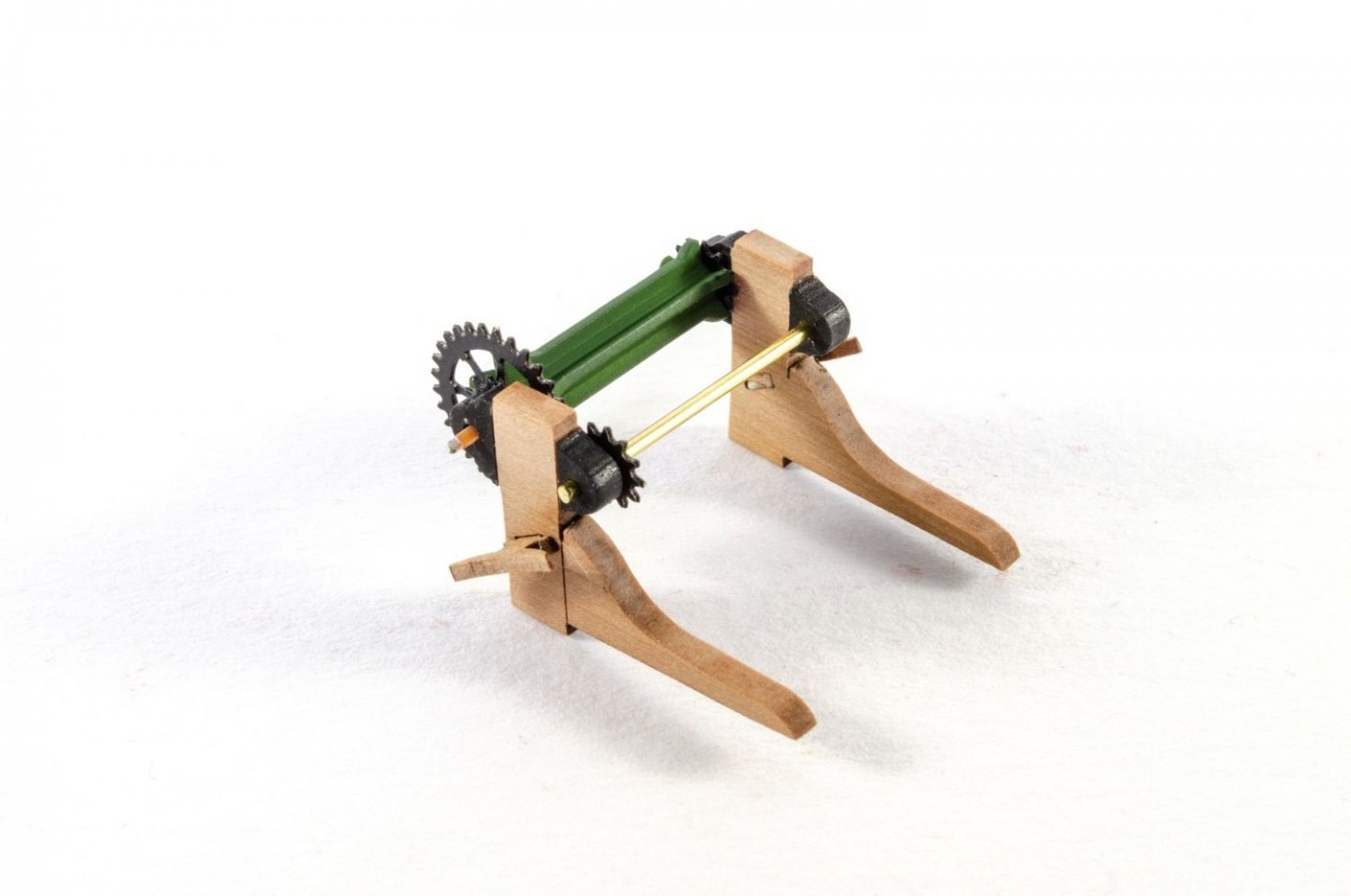
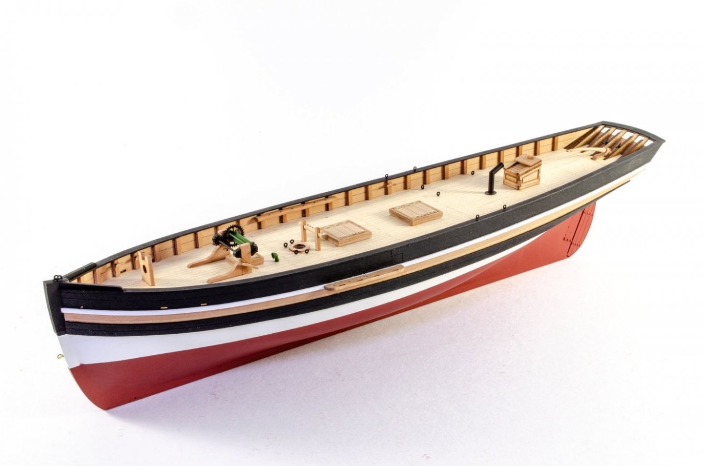
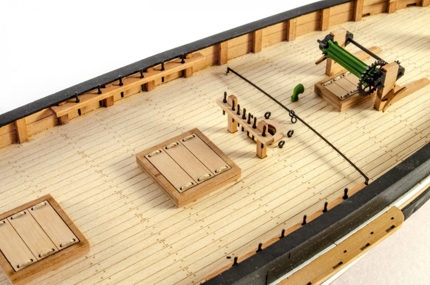
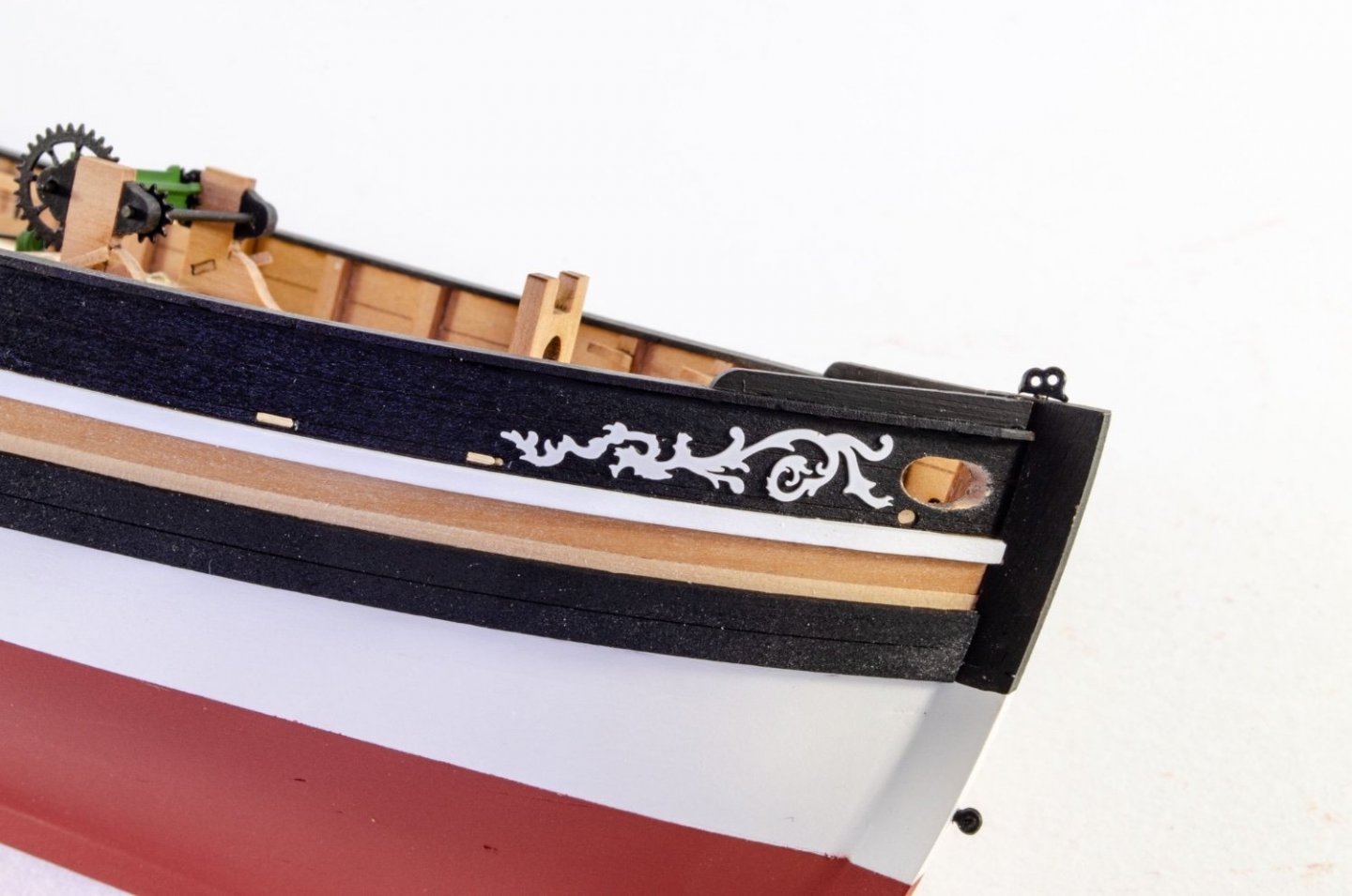
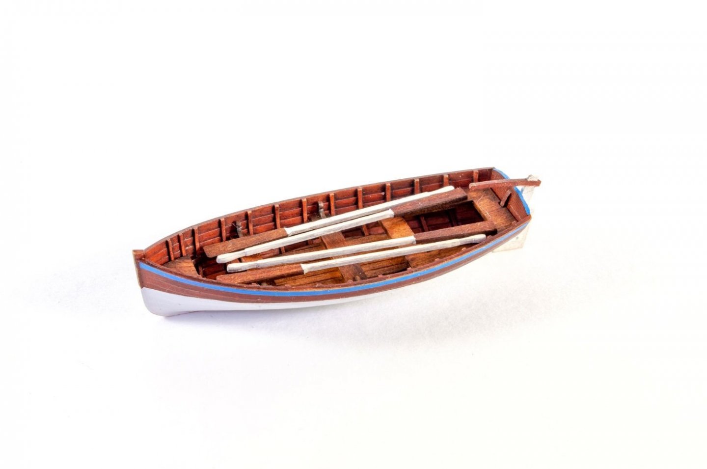
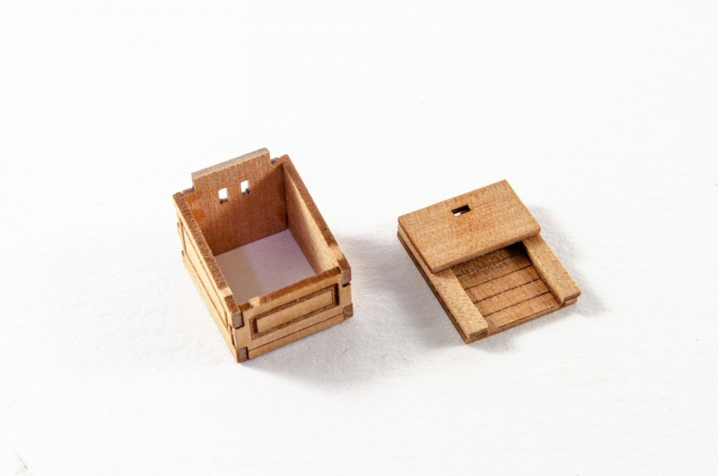
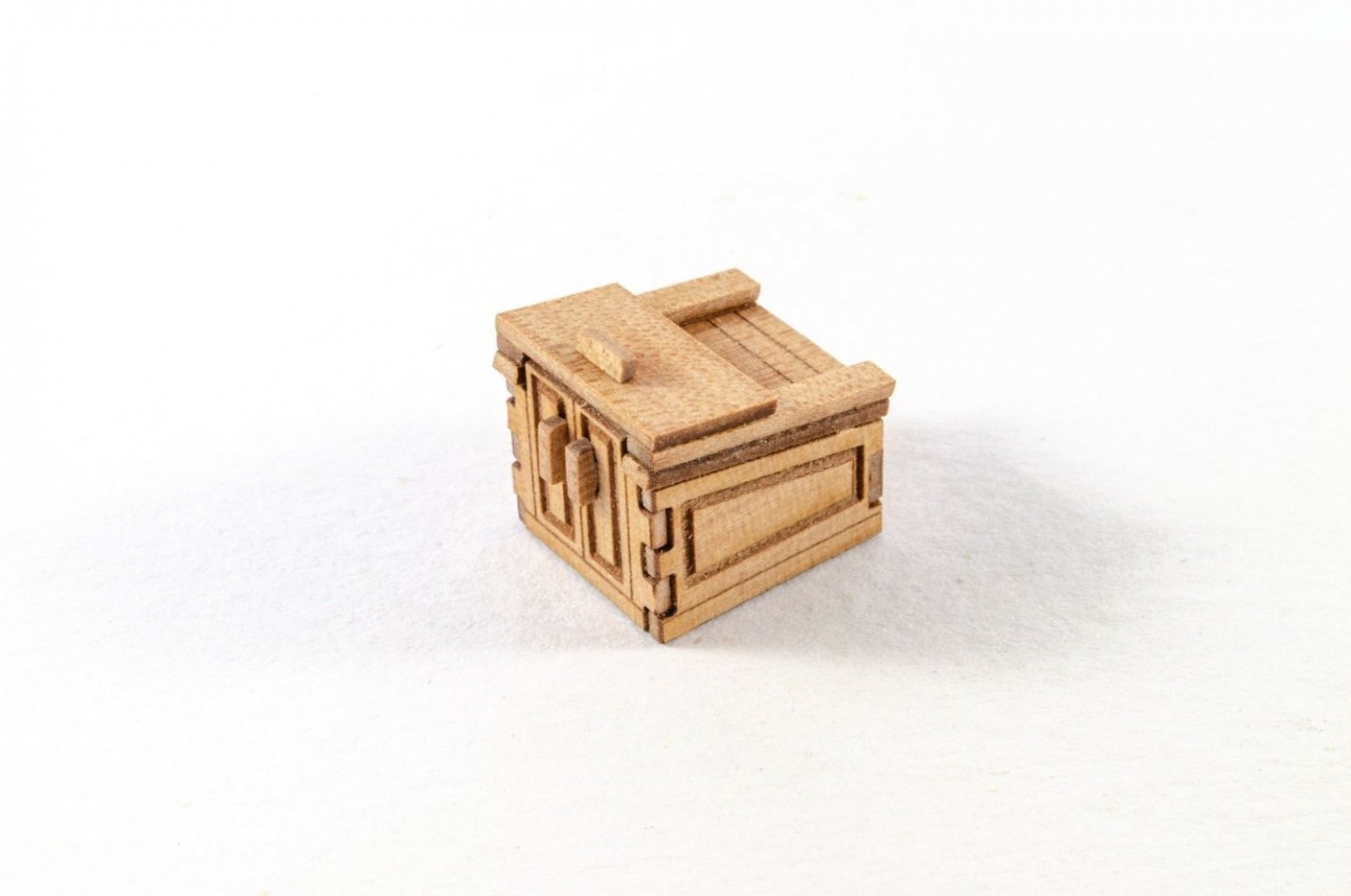
The winch is now built. The drum part is 3D print and first primed then painted in Tamiya flat green. Just remember to put the engraved faces of the winch sides on the outside of the assembly. Some PE is used here for gearing etc. That nice little companionway is now fitted, as it the smoke stack. Provision is also made for pinning the channels. Those are now added too. A smattering of PE is added, such as eyelets and belaying pins. The bowsprit entry hole is filed to allow the down to pass through the bulwark and neatly into the bowsprit support. Some decorative PE work is added. There is some stern work but I won't reveal that until the model is complete A good friend painted this little cutter for me in oils. This will be included in the kit, so I thought I'd lash this down to the deck to complete the ensemble. More next time...


- 16 replies
-
- 19
-
-

-
- Ranger
- Vanguard Models
- (and 2 more)
-
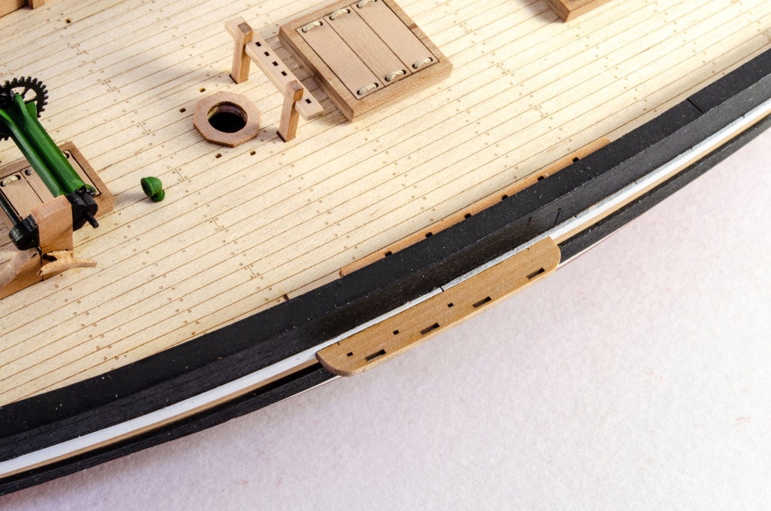
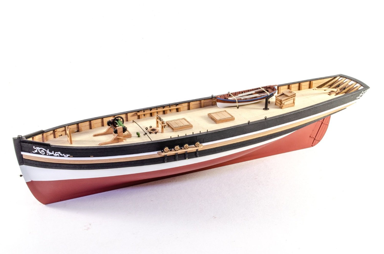
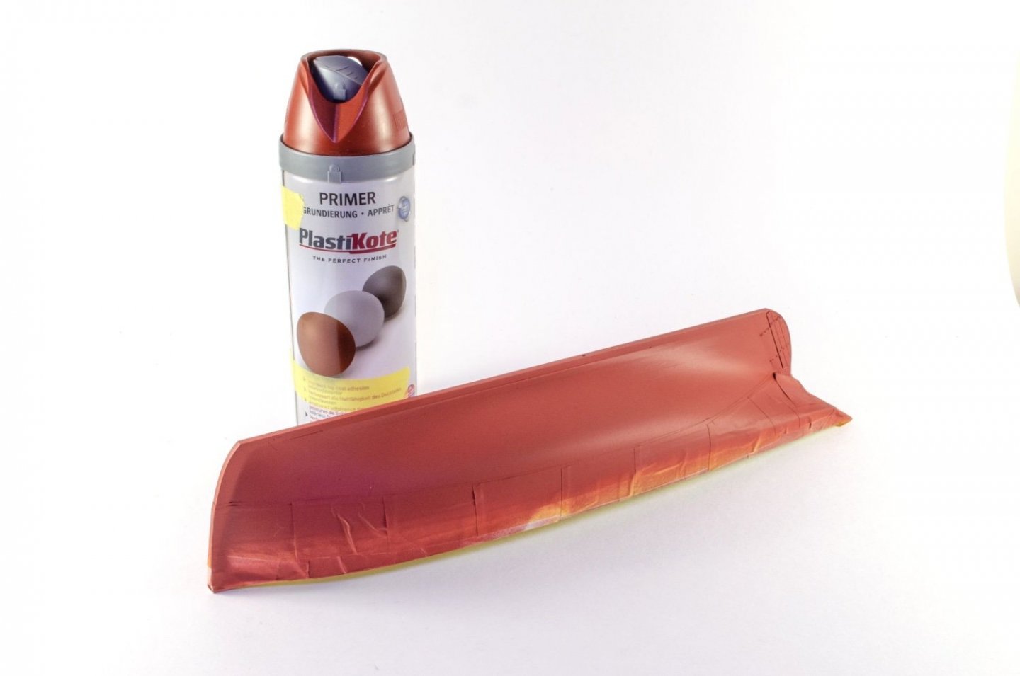
I like Plastikote red primer spray. It coats so very easy in a few passes. This is now added in a few thin coats, and when dry, the model is then unmasked. The upper rails are added as halves, with the join line hidden under the channel position. I'm careful not to poly and paint that area so there's good adhesion when the channels are fitted. That rail is fitted up to the engraved line at the bottom of the bulwark. That also hides the joint between bulwark and planks. The single-piece wales are now glued into place with CA gel. The wales are placed 14.6 - 14.7mm down from the very top edge of bulwark. This means they'll be in the perfect position for the chainplates later. The side gunwales are also two-part, and easily fitted. The stern section is separate too. Time to fit out the decks. As I've had so much of this stuff ready since the beginning of the build, it's real nice to see it being used at last.


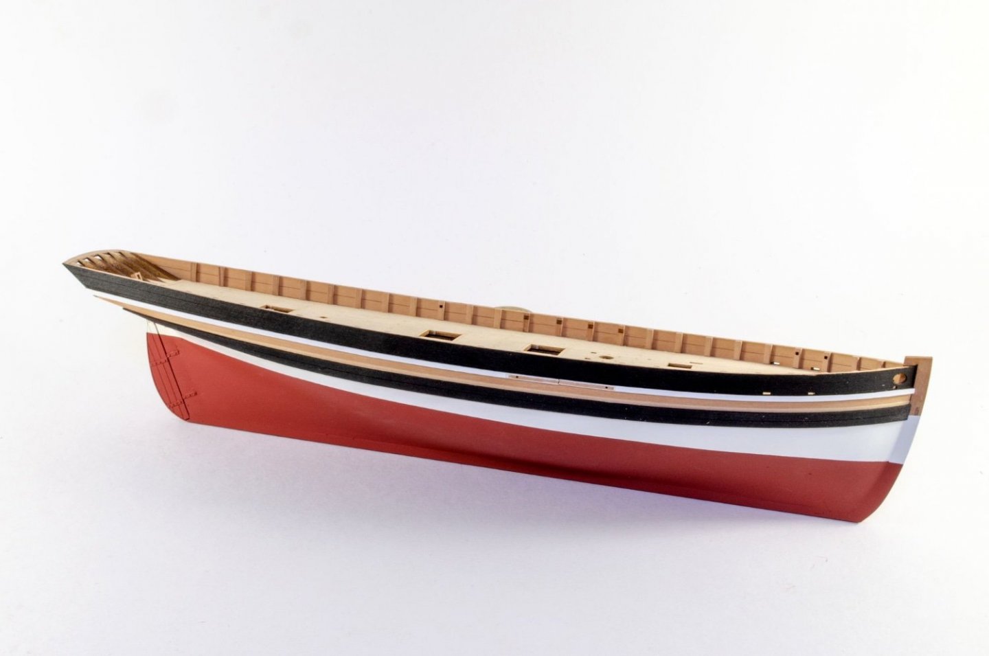


- 16 replies
-
- 9
-
-
- Ranger
- Vanguard Models
- (and 2 more)
-
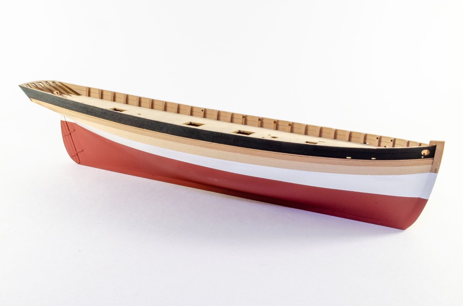
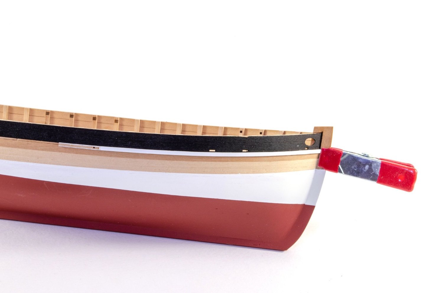
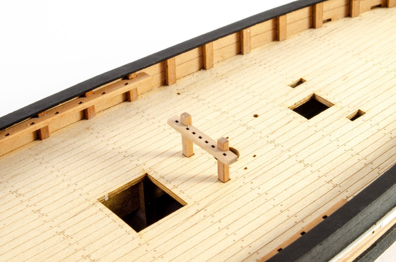
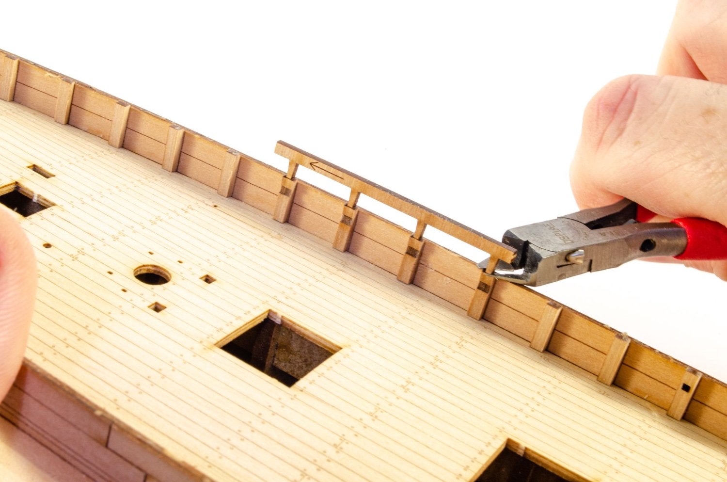
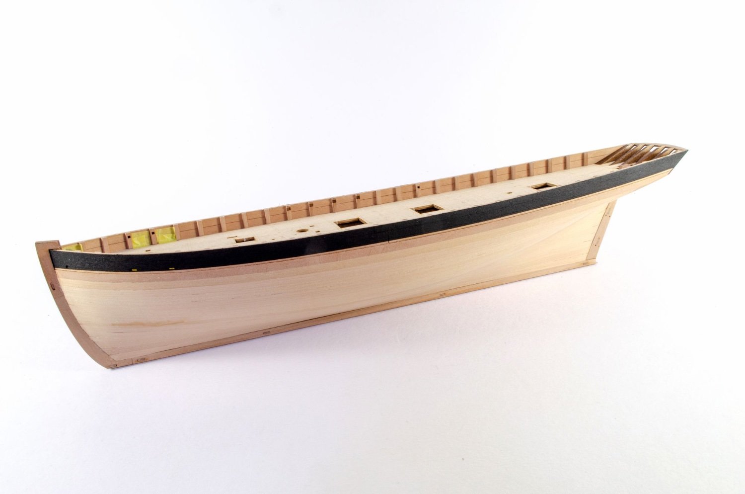
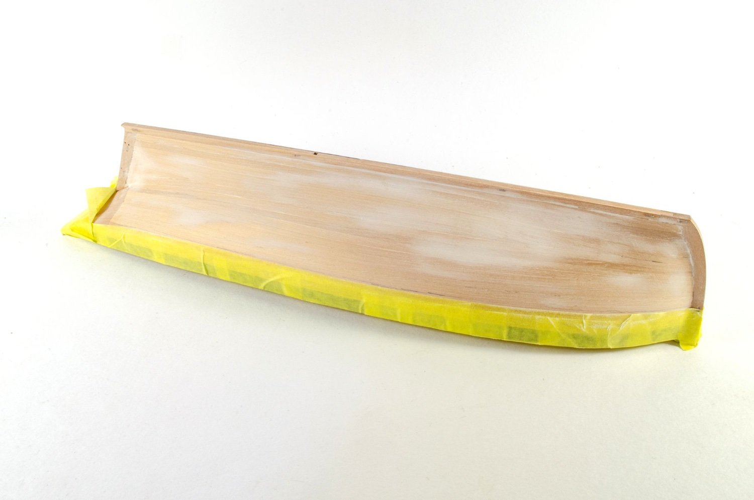
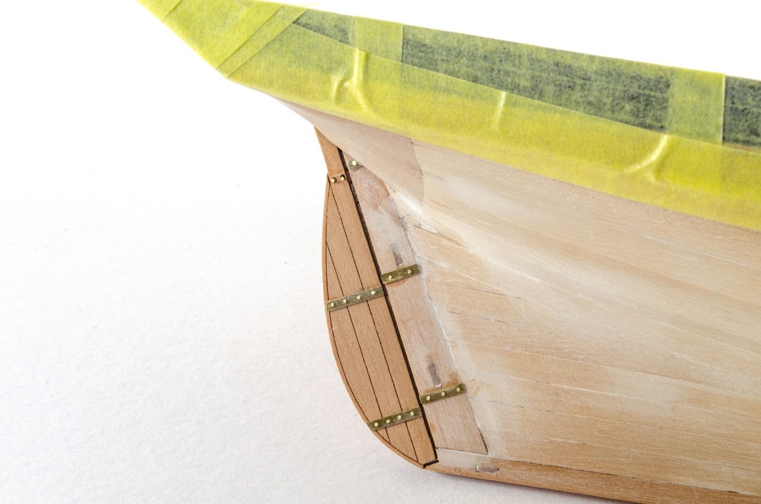
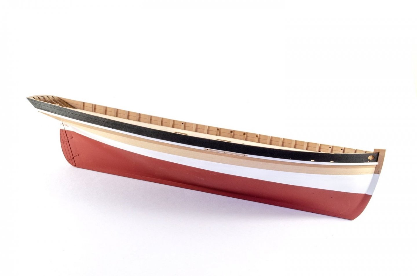
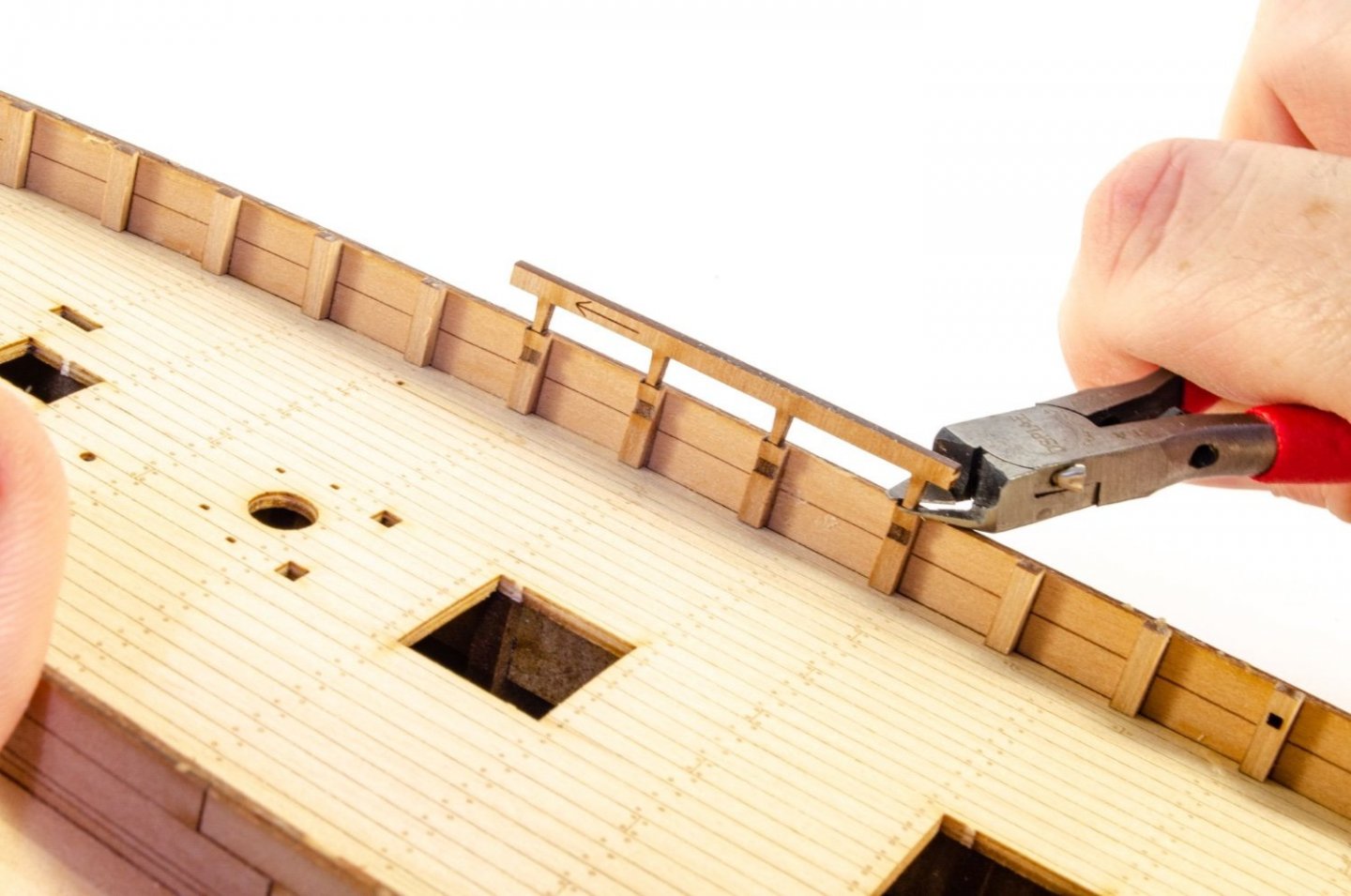
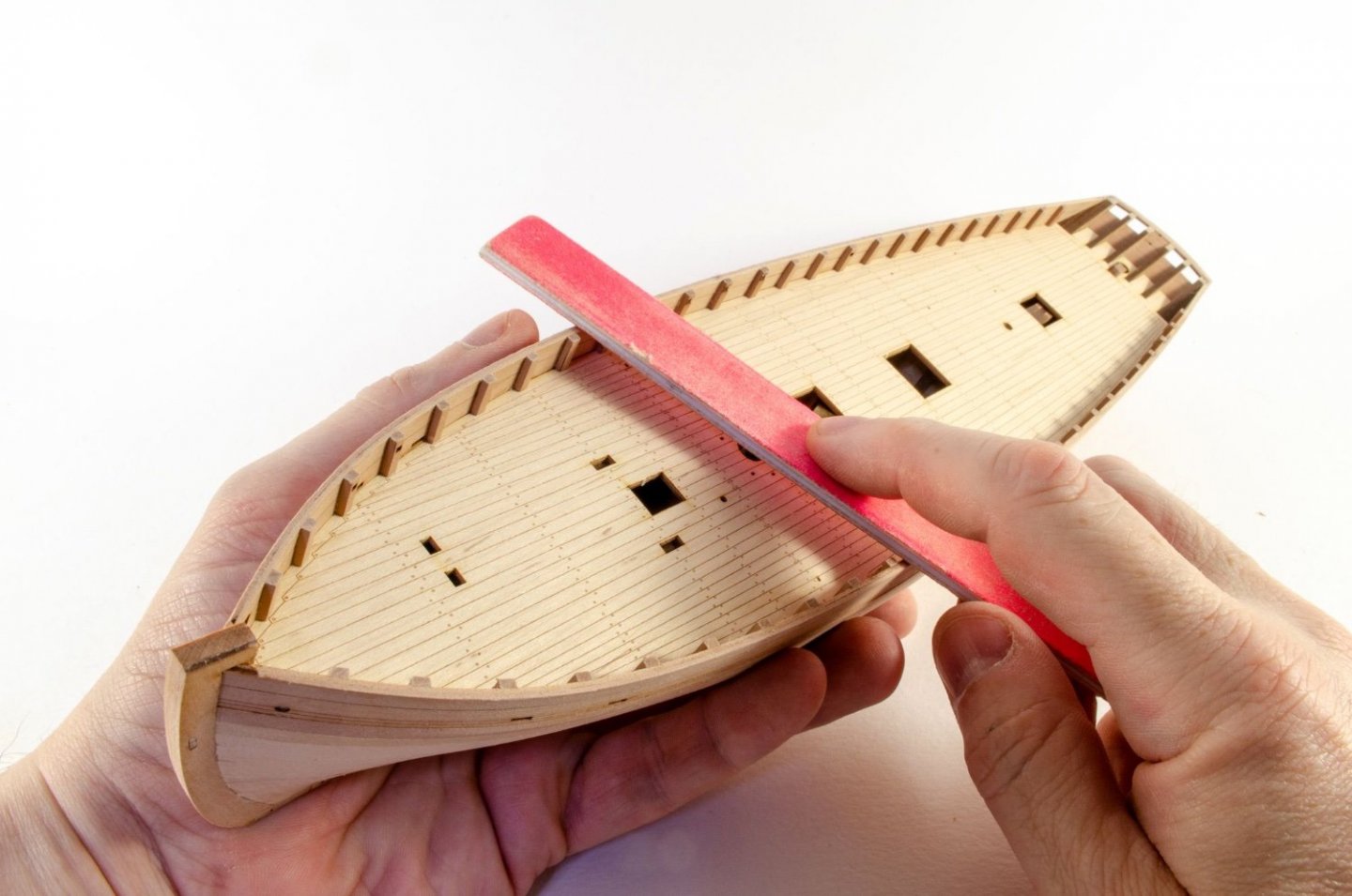
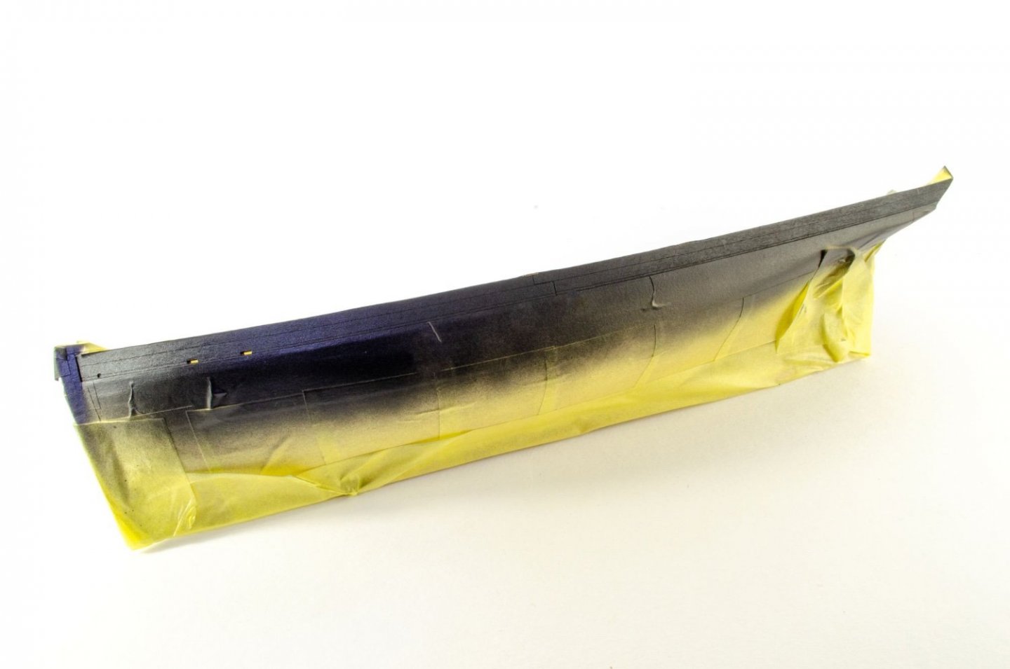
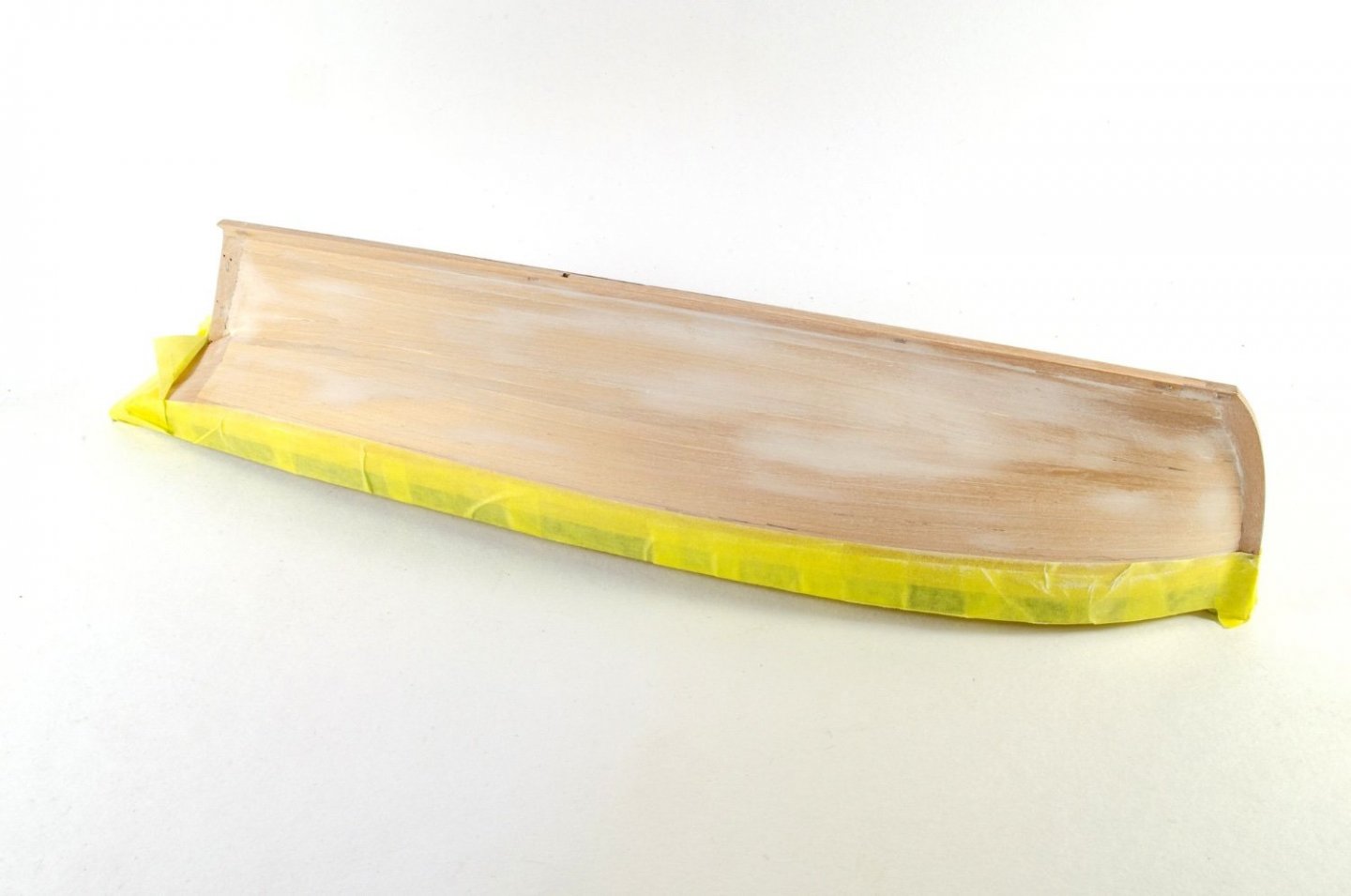
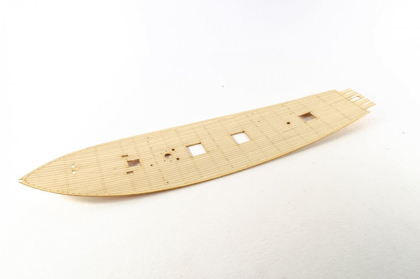
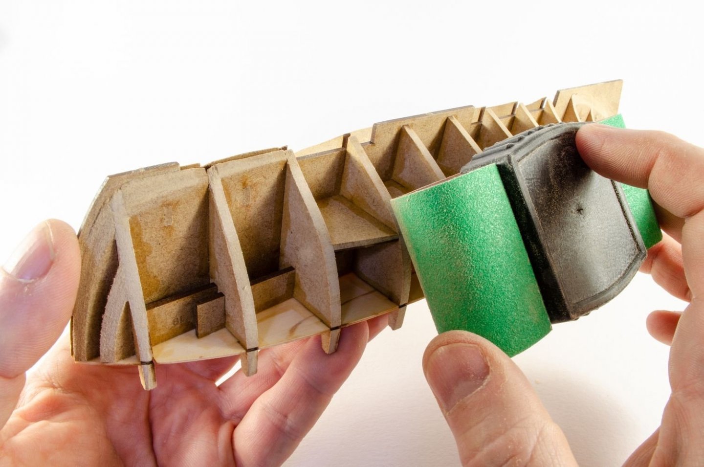
The hull is now very much complete and the next stage is to building the mast etc. That's only a quick job so there'll be another post in the next week, but here's my 3-part update on model so far. Once you have the deck down, the timberheads need to be added. These are so easy to do as each one is cut for you, labelled from A - Y, with four on each side being temporarily interconnected. Engraved letters in the hull explain position. No underside bevelling is needed either as the bulwarks are 90 degrees to the deck. Here you see the connected timberheads. These are done so the spacings are right for the belaying rack. Once installed, the tops of the bulwarks are sanded evenly. All painted areas are first coated in many polyurethane varnish, The model is then masked off in readiness for the black upper bulwarks. The bulwarks are then masked to protect the new paint, and the hull is filled and sanded.......repeatedly, until I am happy that it's as good as I can get it without checking under primer. There is no natural wood shown below the wales, so was happy to fill and sand this, masking to roughly where the bottom of the wale was to be later fitted. PE is now fitted for the rudder hinges, and the rudder glued into position. The rudder itself is a 3-layer sandwich with engravings on the outer faces. The hull is now masked again and white primer sprayed before small refills and sanding sessions. The final white coat is then applied. When dry, a waterline is added to demarcate the area under which will be red oxide.


- 16 replies
-
- 7
-
-
- Ranger
- Vanguard Models
- (and 2 more)
-
I used to do the same with ParcelForce. A good way of dealing with it was asking for the charge to be separated from the duty, and then the duty paid. The parcel was then released and when they then invoiced you for there fees, they couldn't legally enforce it (because you had to contract with them) and the invoice was binned. ParcelForce then stopped that happening. I have never since had success in getting a package released from any courier without the fees being paid prior. They hold your parcel and the 'third party' argument or the 'final mile' argument simply didn't work. If you know how this is bypassed, and I've spent so long navigating this problem, PLEASE let me know what you say/send etc.
-
posting problems
James H replied to bruce d's topic in Using the MSW forum - **NO MODELING CONTENT IN THIS SUB-FORUM**
Fixed -
No, there's been zero change in any of our requirements for almost 10yrs.
-
All my photos are saved through Photoshop are exported in 'save for web - legacy'. This brings the images down to a few hundred kb.
-
Many of my pics are 2000. The system will adjust accordingly.
-
I was told by an insider at a main hub where customs are assessed in UK, is that just about everything from the US is held up for customs to get their £ out of you, while from anywhere else (including China and Japan), it's quite arbitrary.
-
You can do max 1500 wide, although I tend to leave around 2000 and let the system adjust. As for data size, you can use anything from a few kb to a fee meg. Pretty flexible.
-
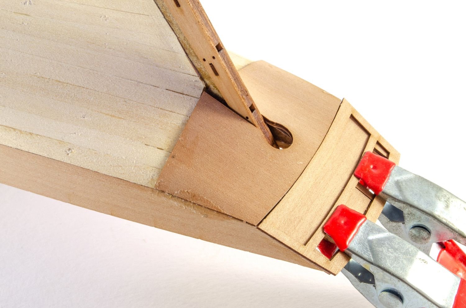
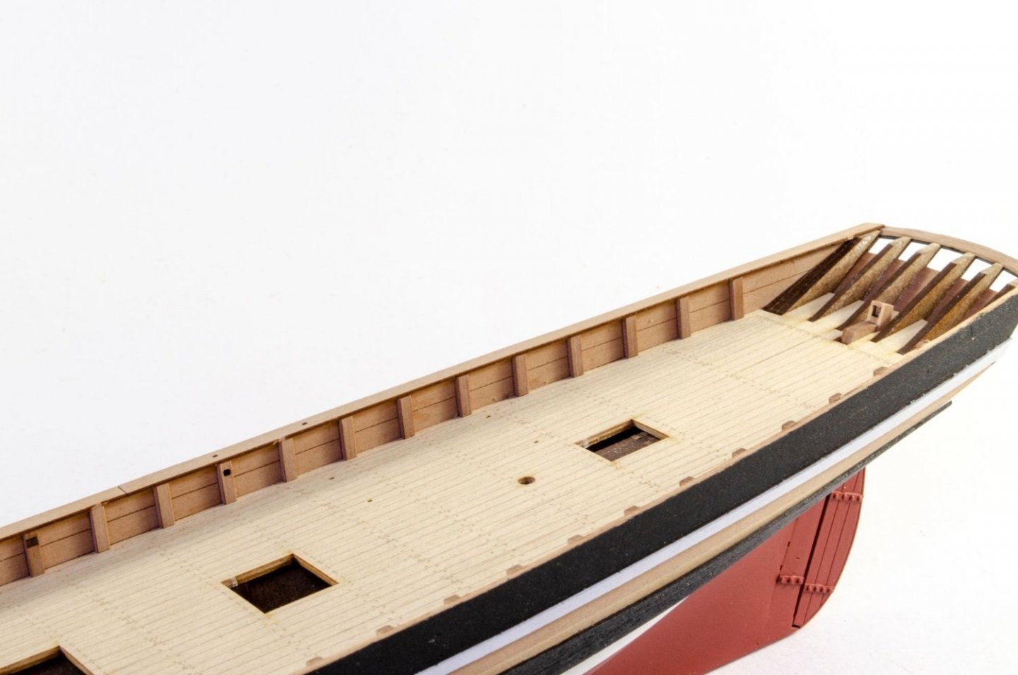
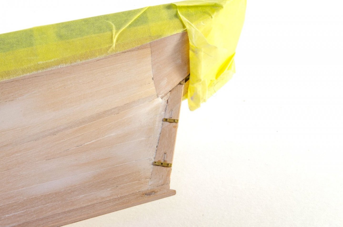
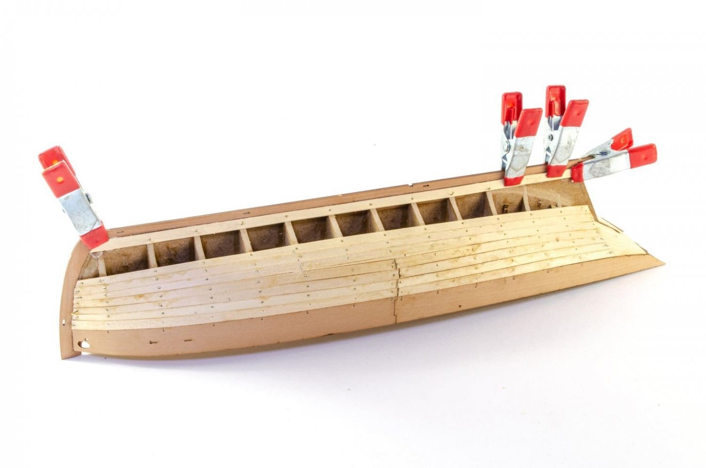
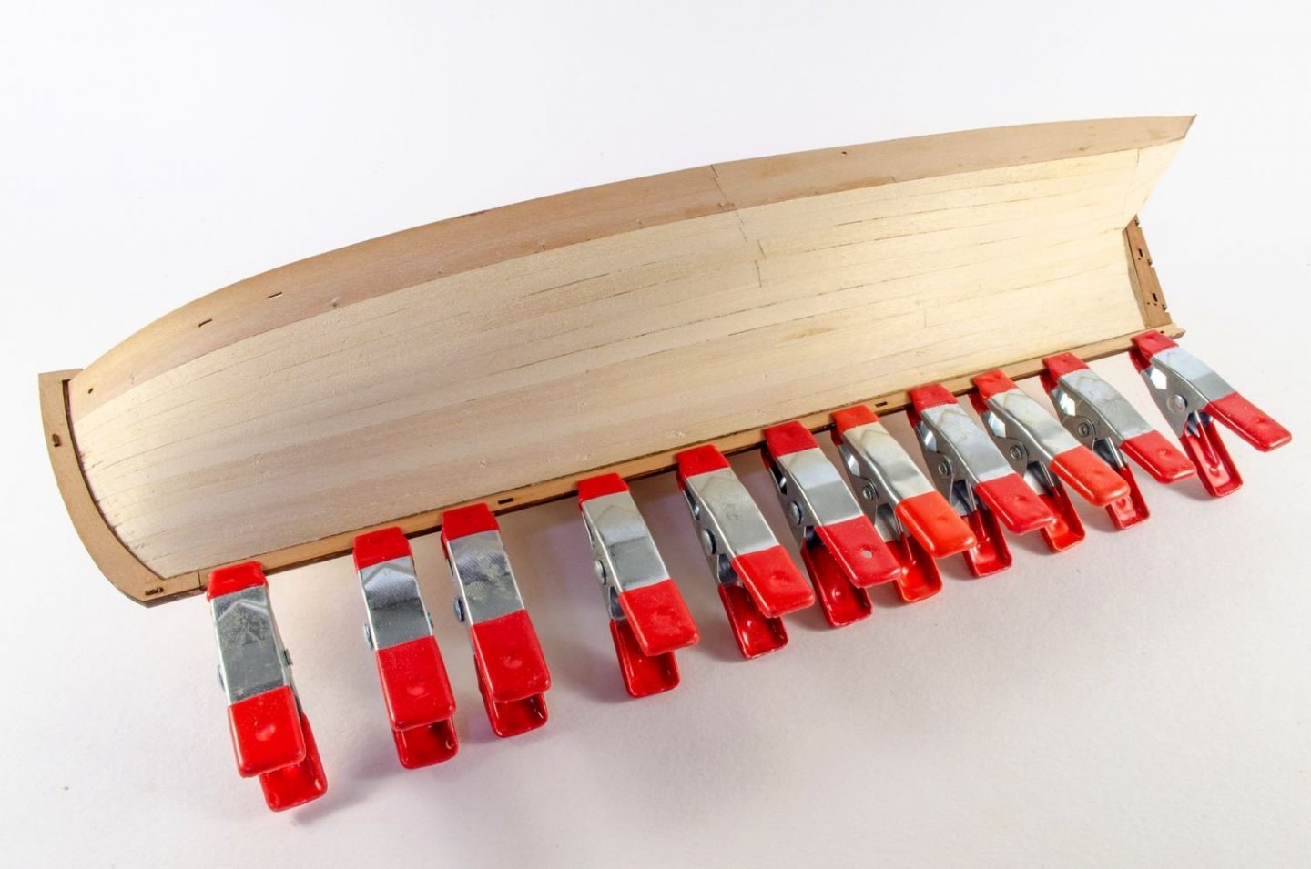
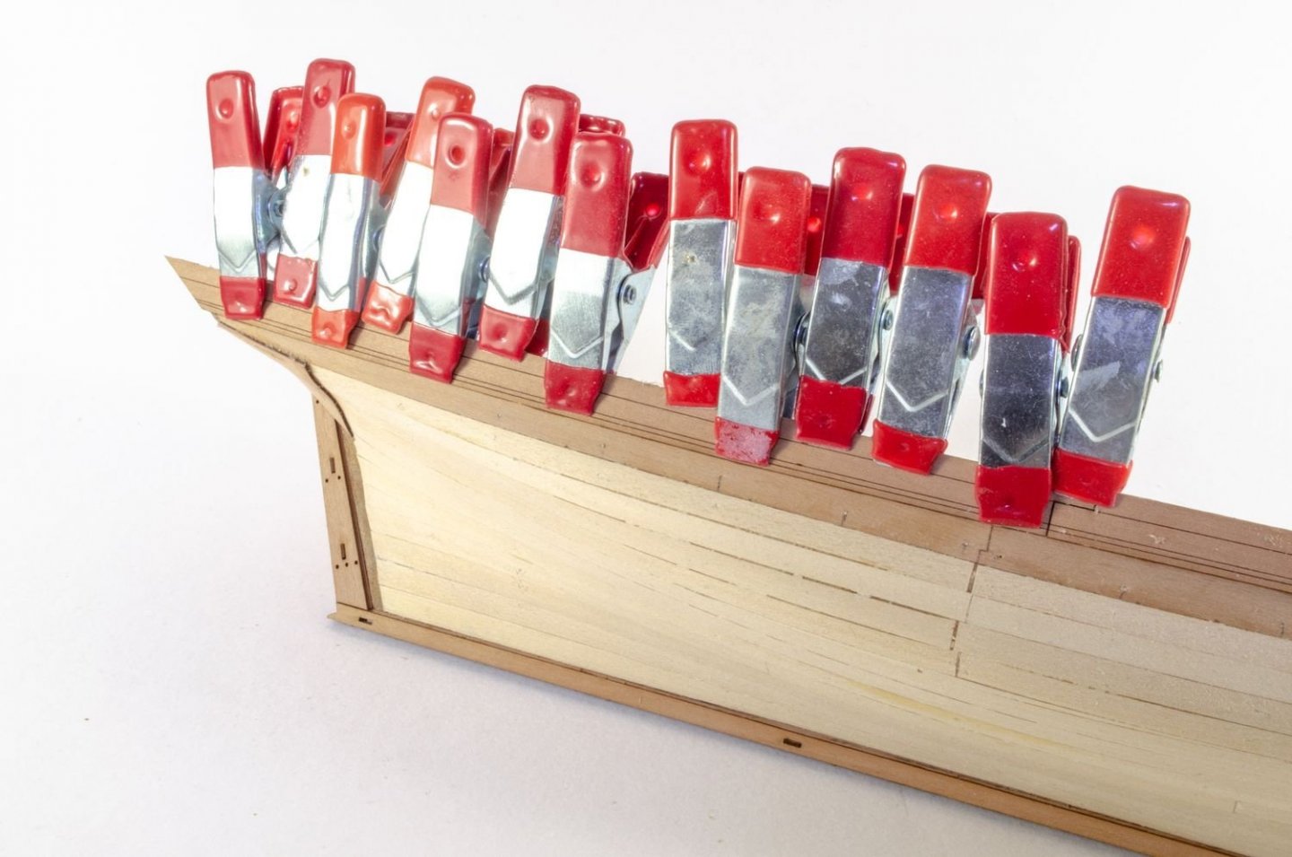
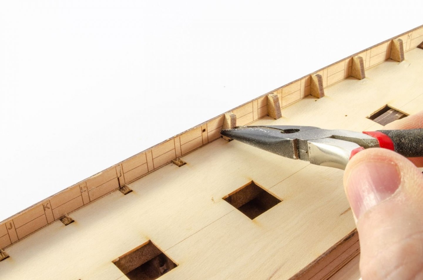
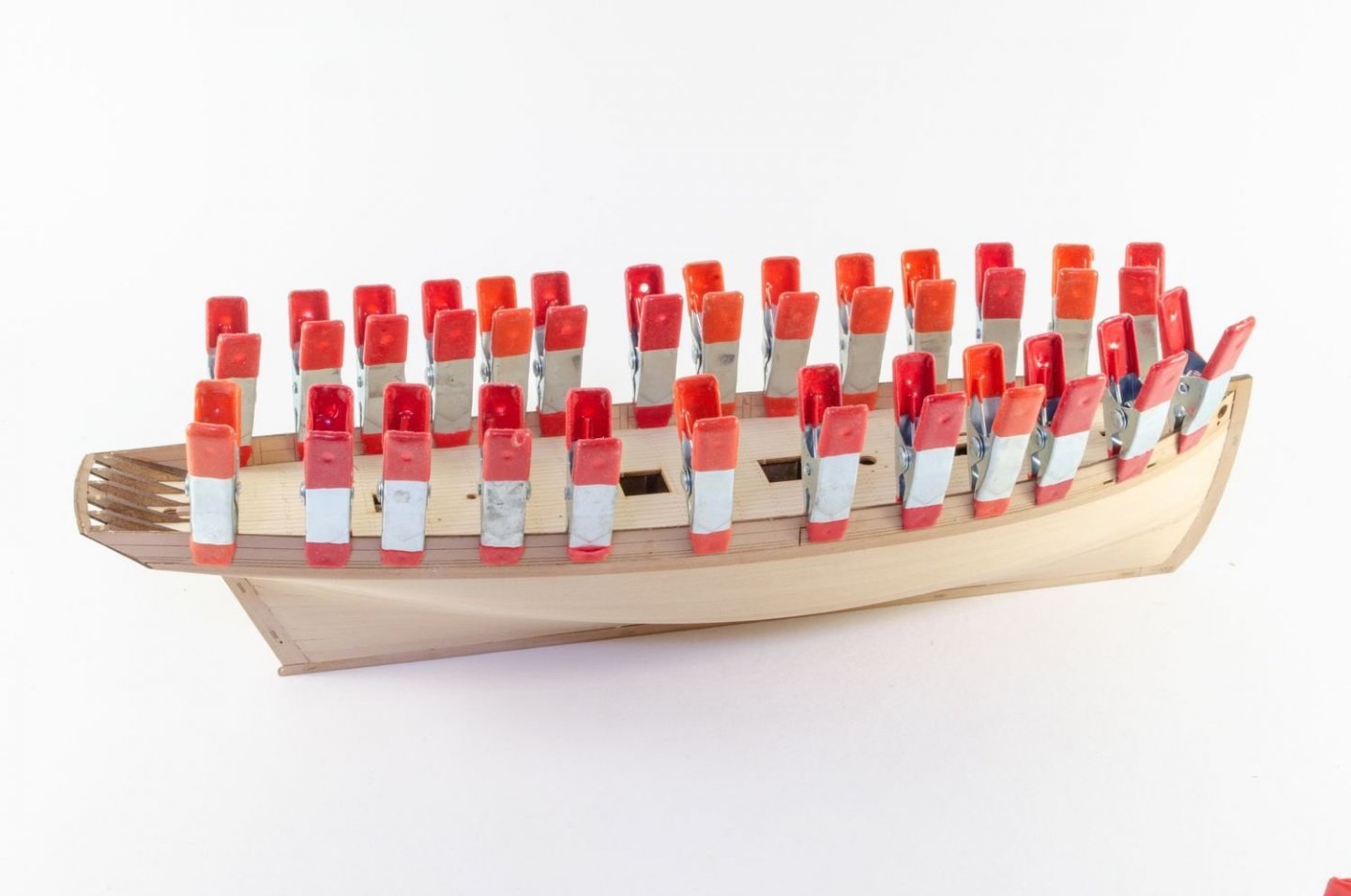
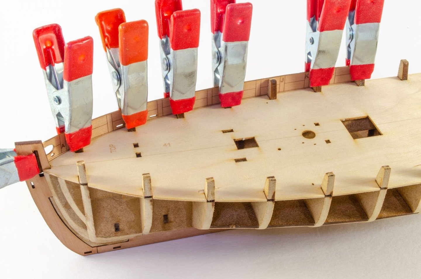
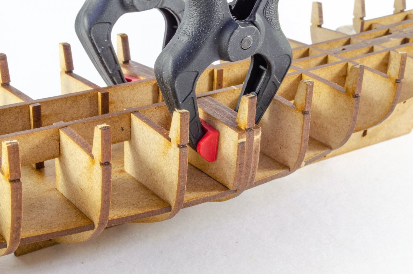
Another quick update to bring the hull to date with where I am. I have done loads of other stuff, but I'll keep this log in chronological order. Onto planking. One untapped row, and then onto tapering. I split these lengths in half to show a beginner that they can do this if they wish. You really don't need to otherwise. The inner bulwarks are now trimmed back to the stern timbers and then sanded flush to the stern board can be fitted. This is then sanded flush with outside of inner bulwarks (not shown in this log). If you've followed any of these build logs or built a VM kit, you'll be familiar with how the keels are then faced with another layer of pear, creating a ready rebate for you to neatly plank up to. The outer stern board frame is temporarily clipped into position (NO glue!) so that I have the position to fit the pear lower counter. The counter is then sanded flush with the sides of the hull. Now, the outer bulwarks can be glued into place, and then sanded flush with the stern fascia. One of the bits I like doing. The MDF bulkhead ears are now twisted on pliers and the remnants sanded flush with the deck. Ranger comes with an engraved maple veneer deck. This is test fitted to the model and adjusted (if necessary) so it lied flat on the ply deck and across the camber. This is then glued into place and a 'few' clamps used to hold it down around the edged while it dries. These little 2 inch clamps are great for this. More next time.


- 16 replies
-
- 15
-
-
- Ranger
- Vanguard Models
- (and 2 more)
-
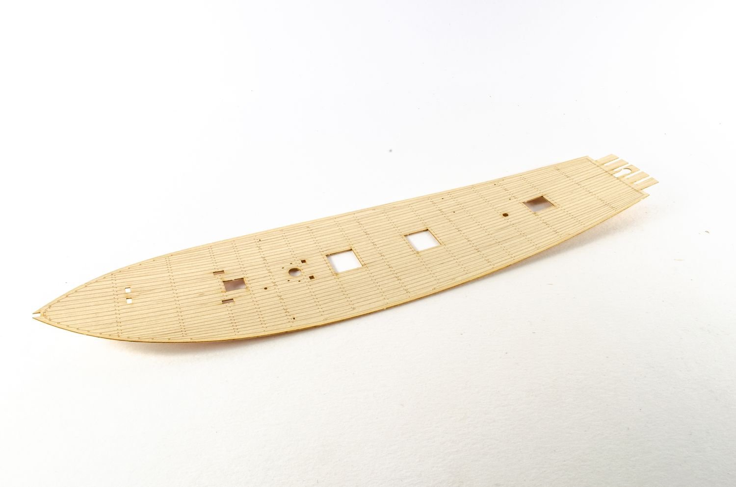
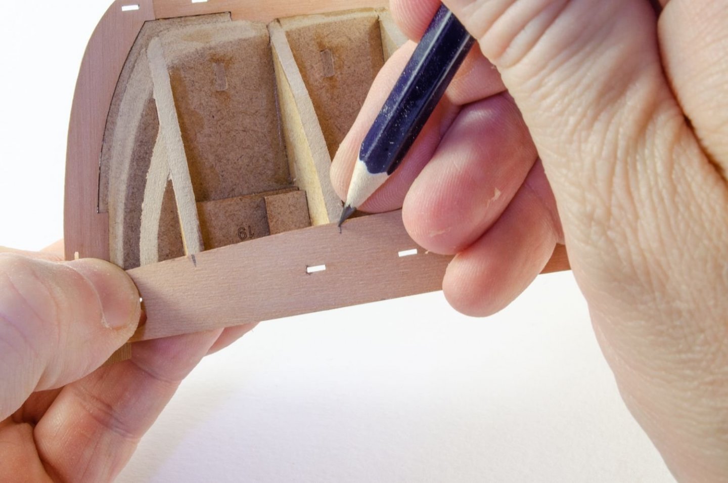
Adding the deck is easy as it bends enough to be able to slot it into the bulkhead ears and into the little slots at the base of them. Those lock the deck into place and with it lying flat across all bulkheads. Fairing took my only about 20 to 30 mins on Ranger. Nice and simple with no double-guessing anything. The 2mm pear prow and keel are now glued into place. These can only plug in one way, so no mistakes can be made. On Ranger, the inner, lower counter is maple veneer. This needs no soaking to fit the curves, and just wraps around the area as shown. In fact, there's NO need for any parts soaking on Ranger. She's a water-free zone during building. The inner bulwarks are supplied in halves. These are nice and shallow and you'll find no tendency for them to veer away from the bulkheads, fore and aft. This is why Ranger is most definitely idea for a total beginner. I marked the bulwarks with the bulkhead positions so I could pre-drill some holes, ready for pinning to the bulkheads. Also remember NOT to glue to the model above deck level as those MDF ears will later be removed for the timberheads.

- 16 replies
-
- 8
-
-
- Ranger
- Vanguard Models
- (and 2 more)
-
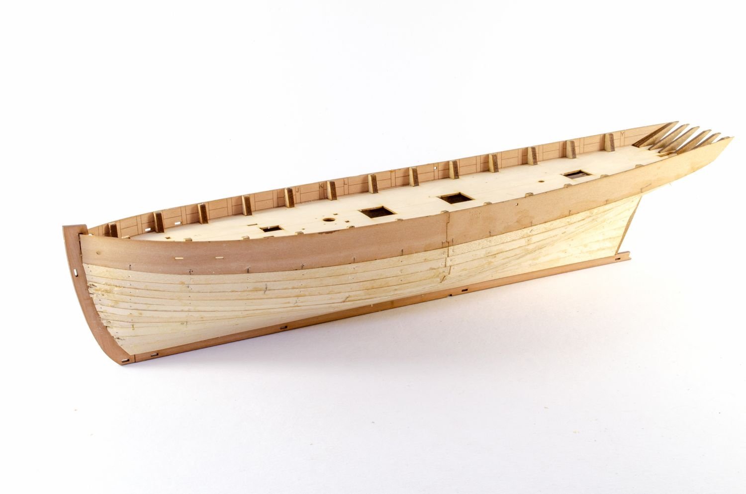
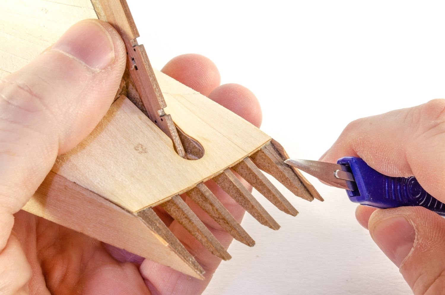
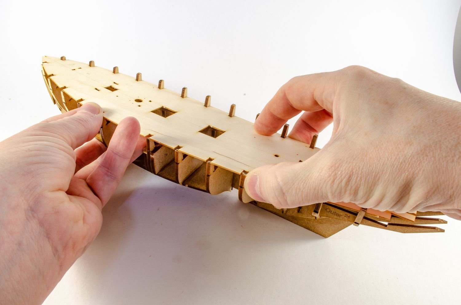
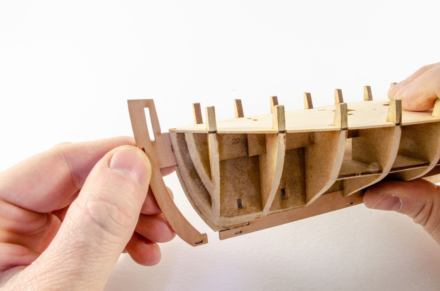
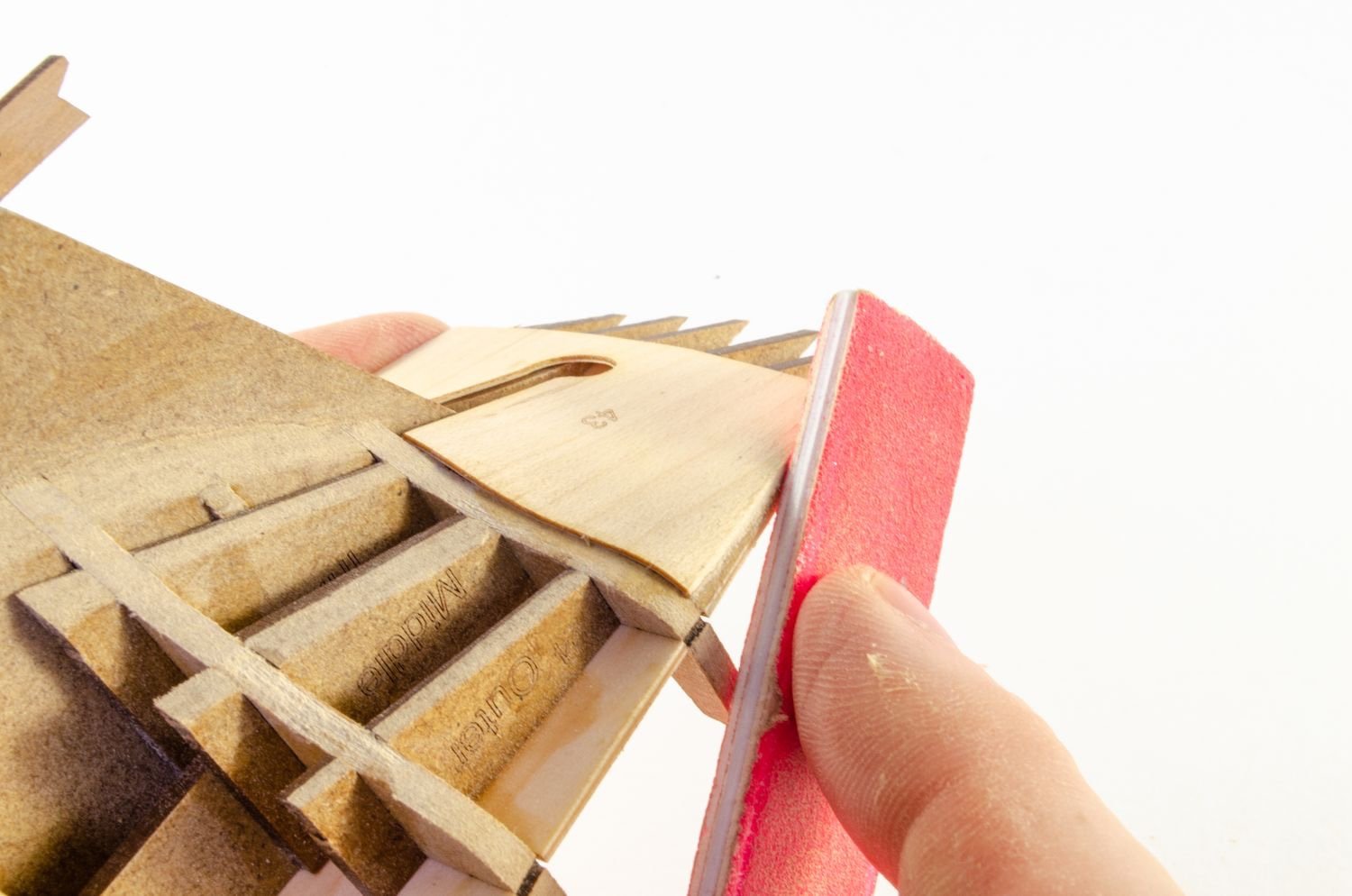
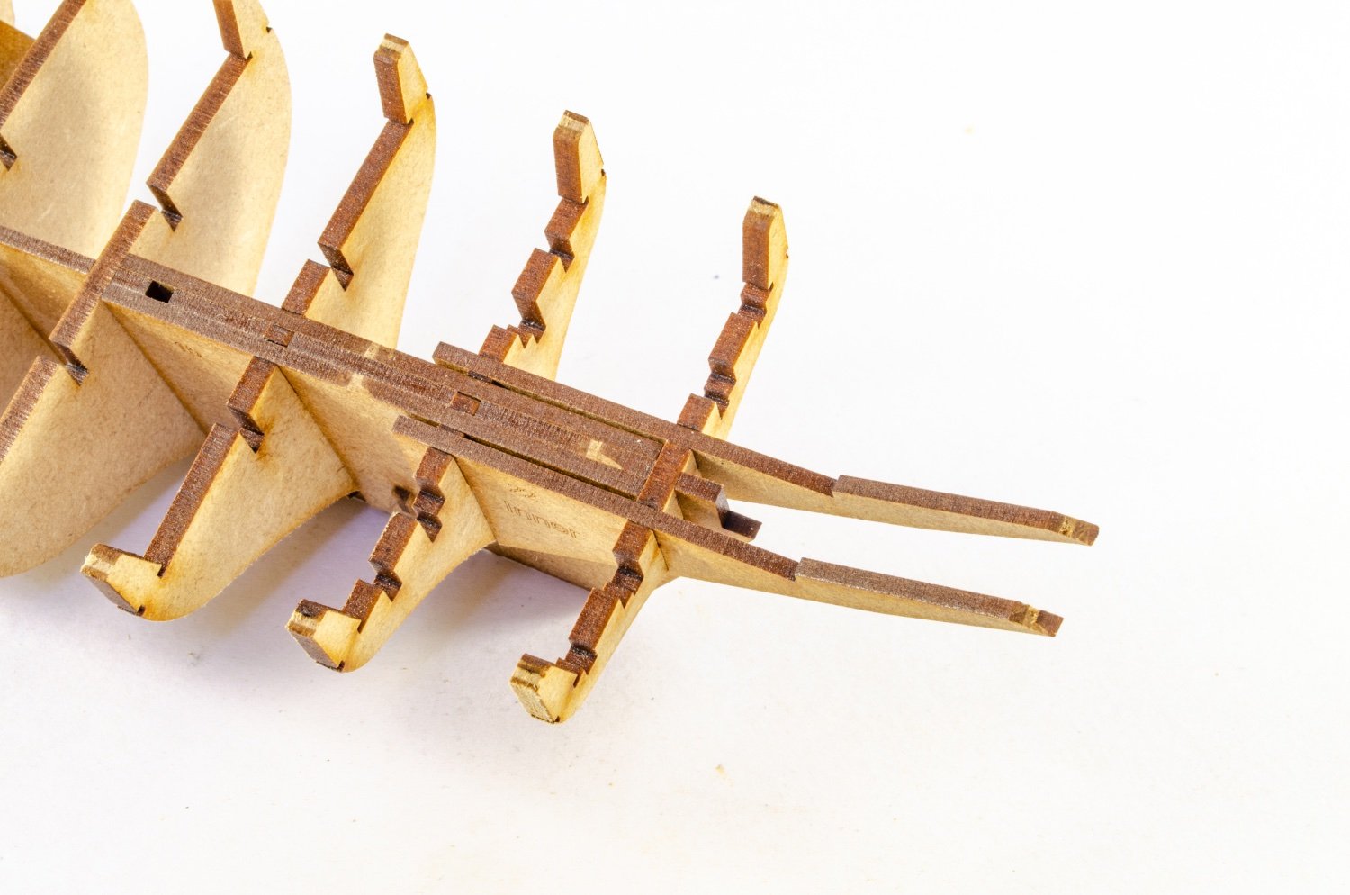
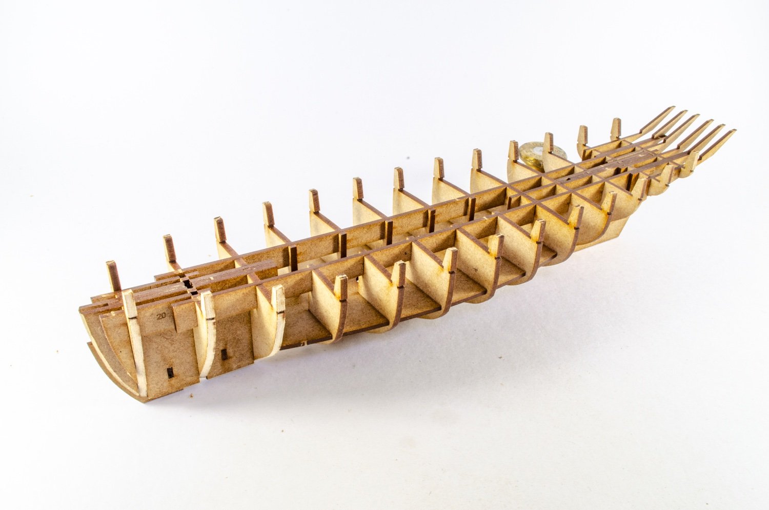
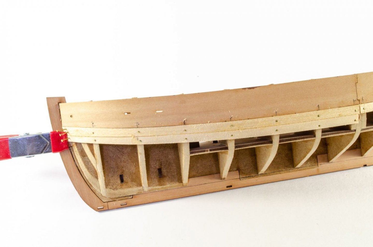
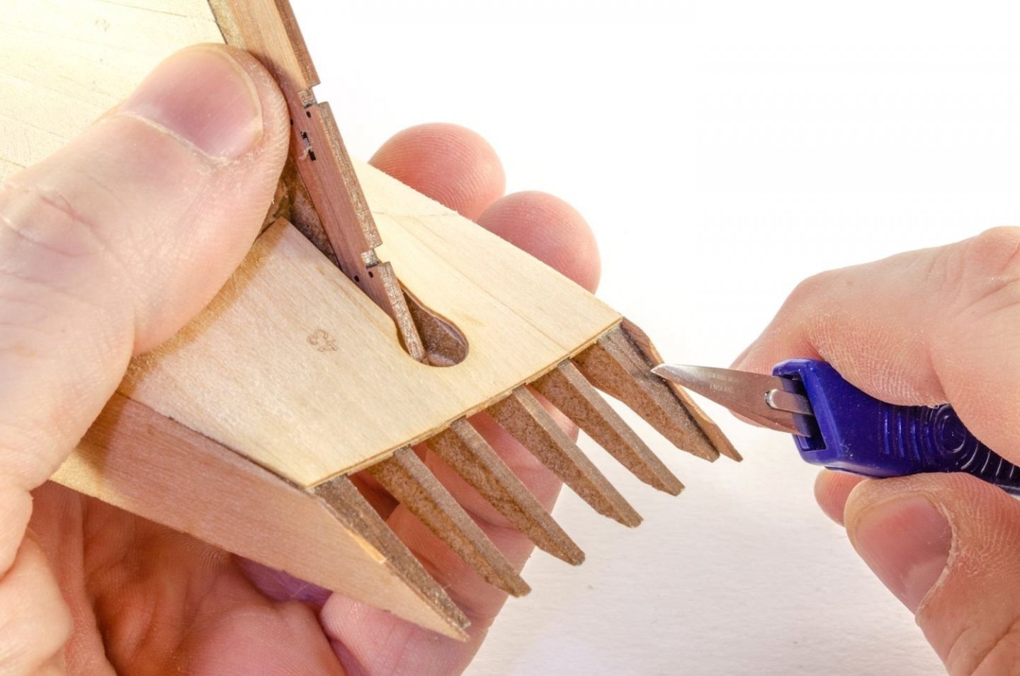
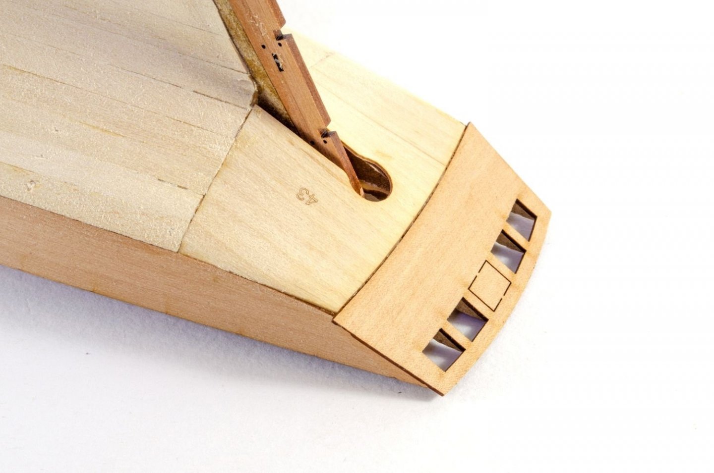
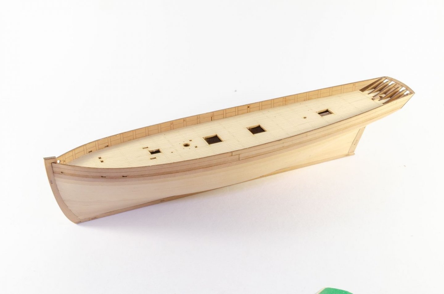
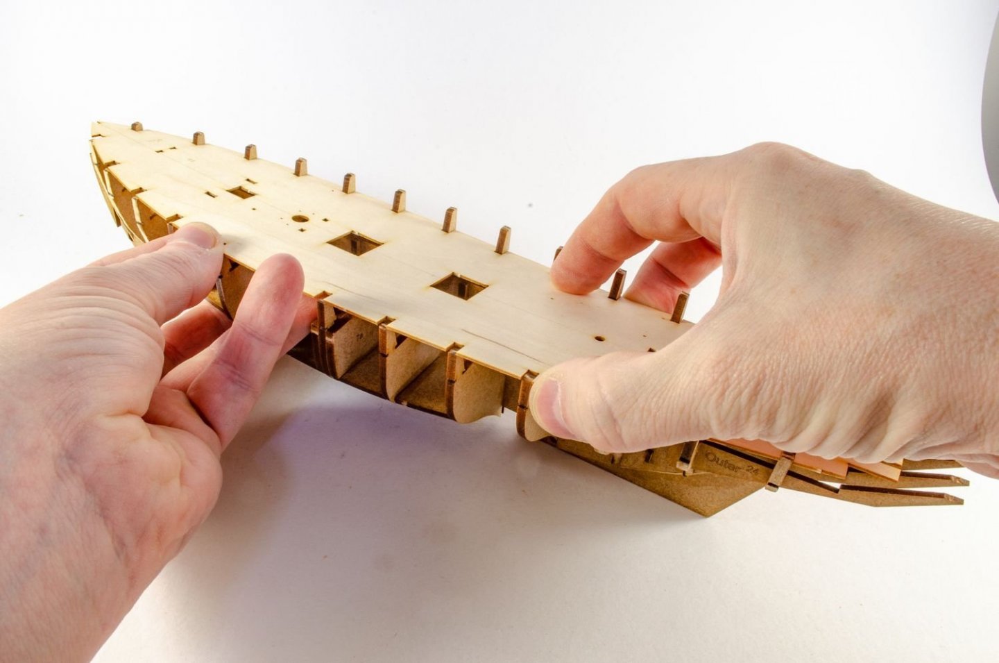
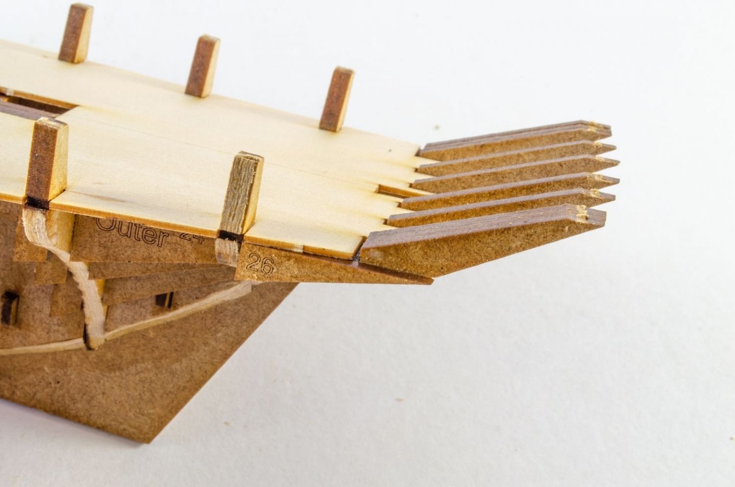
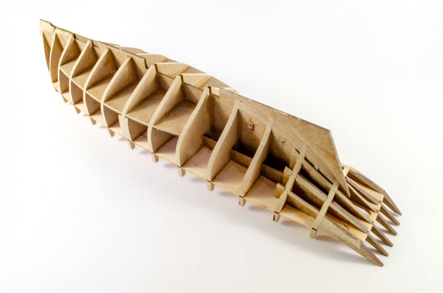
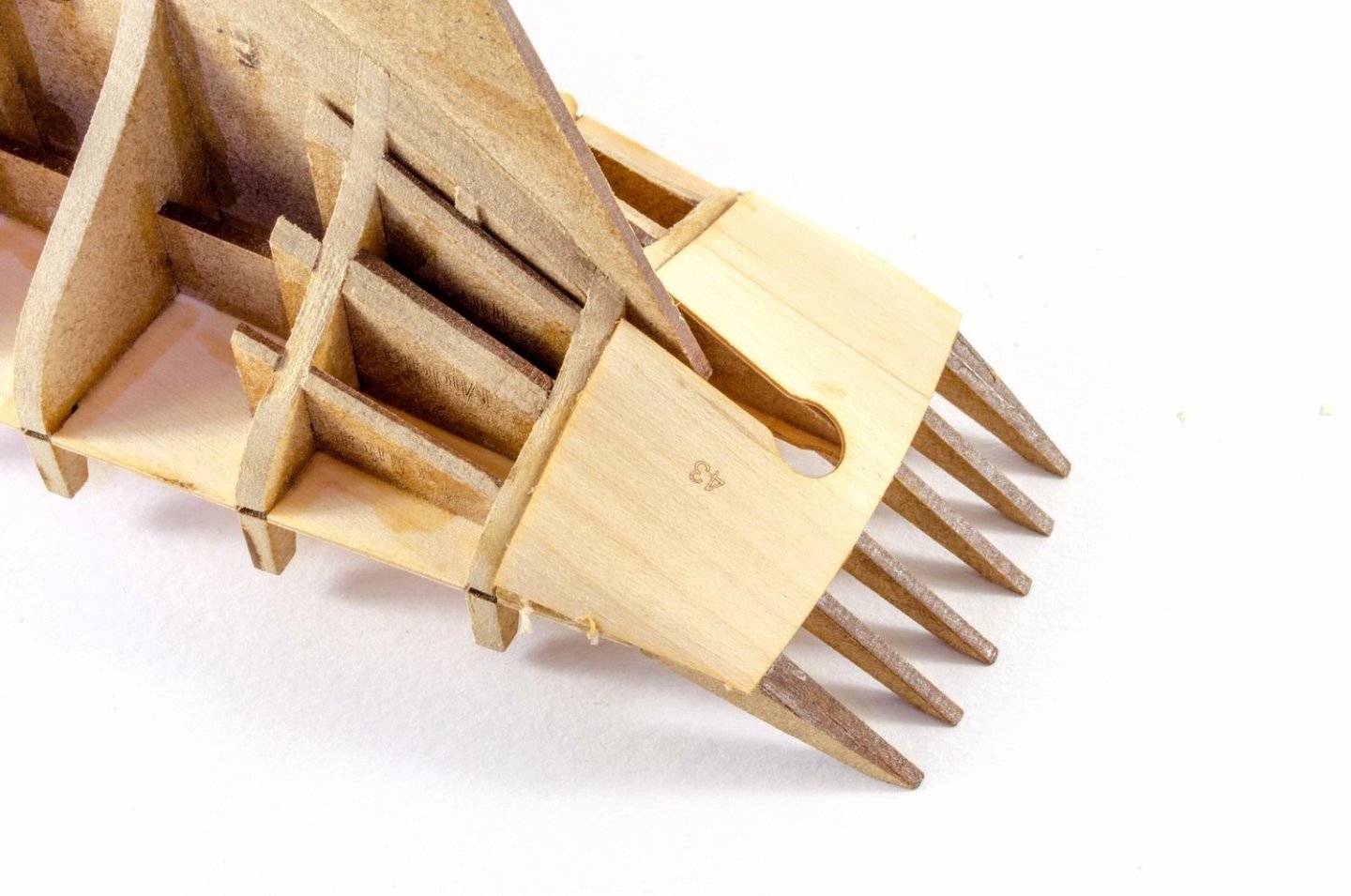
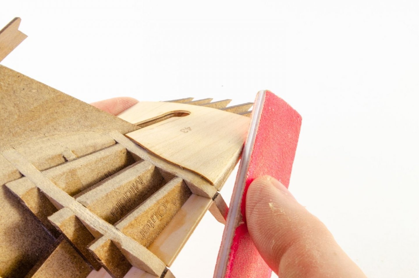
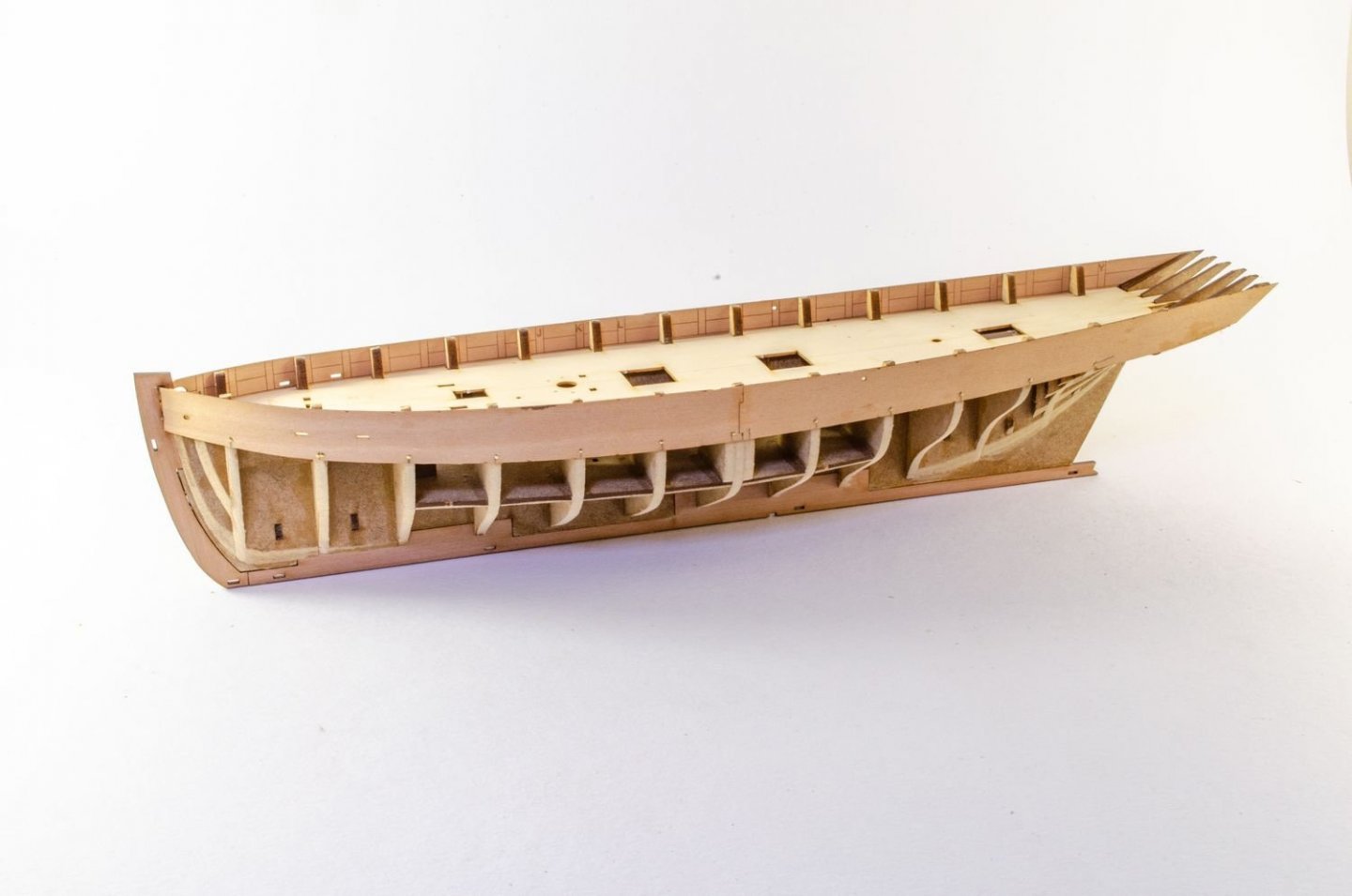
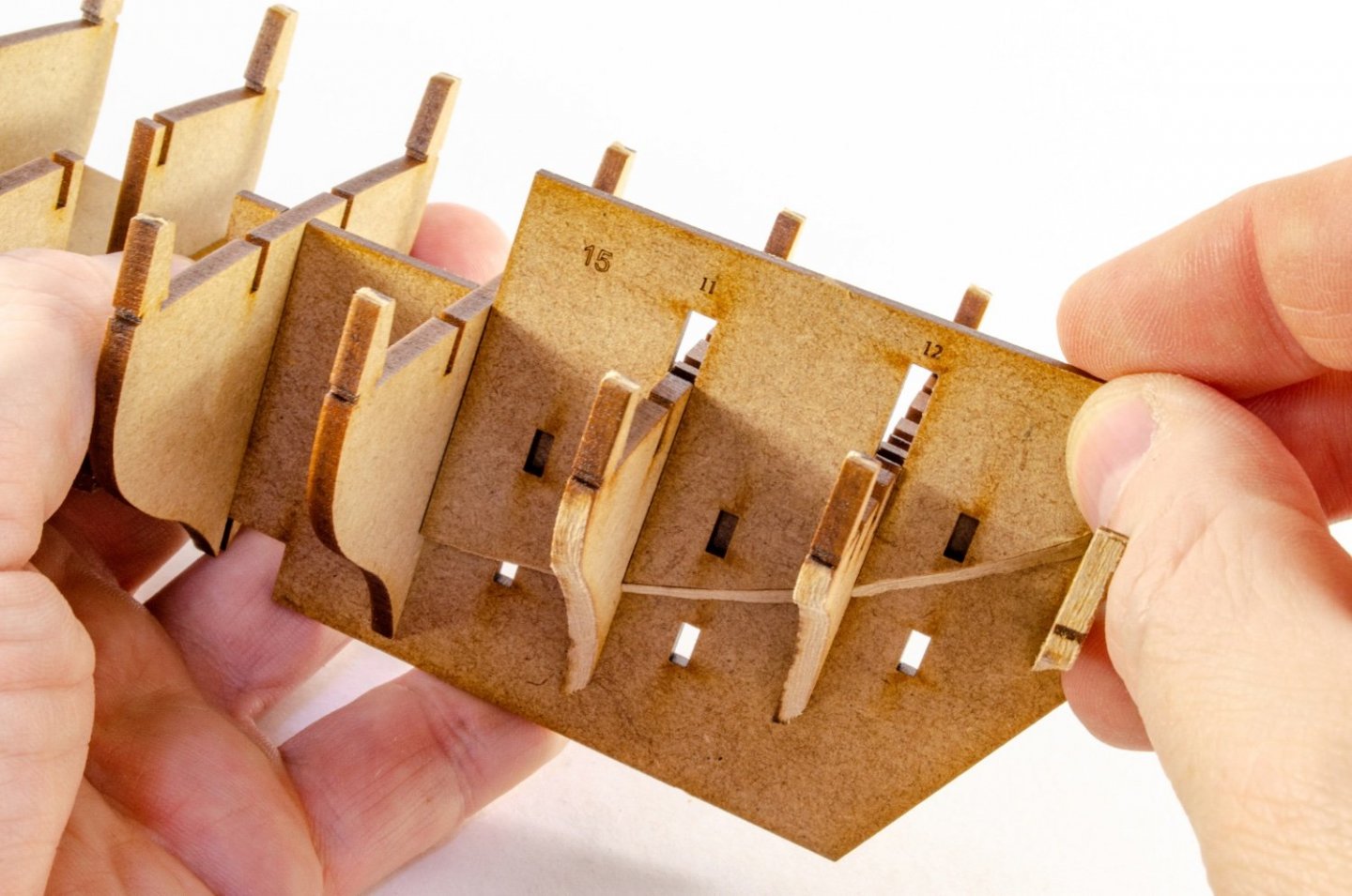
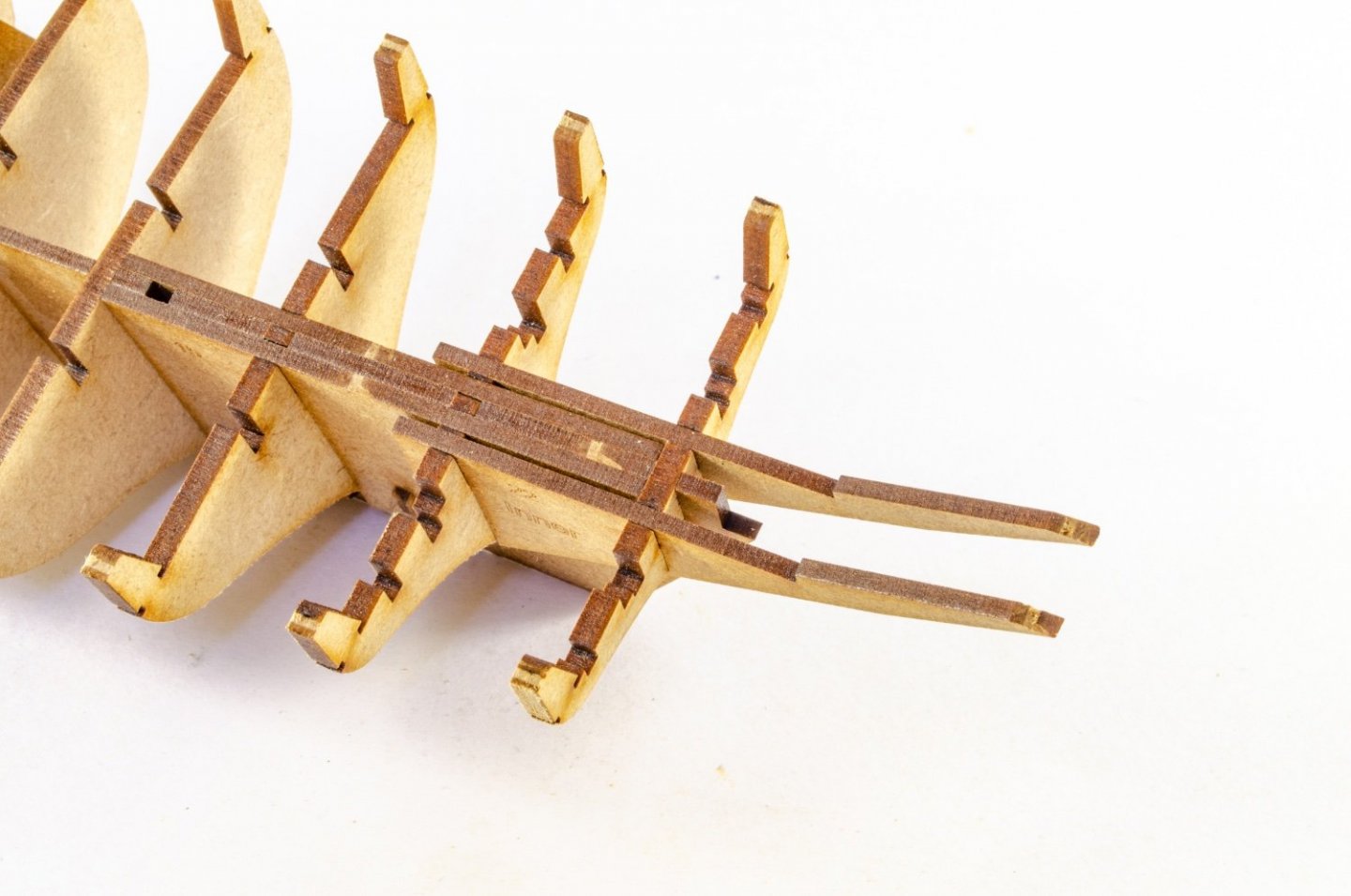
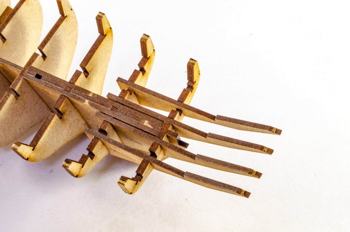
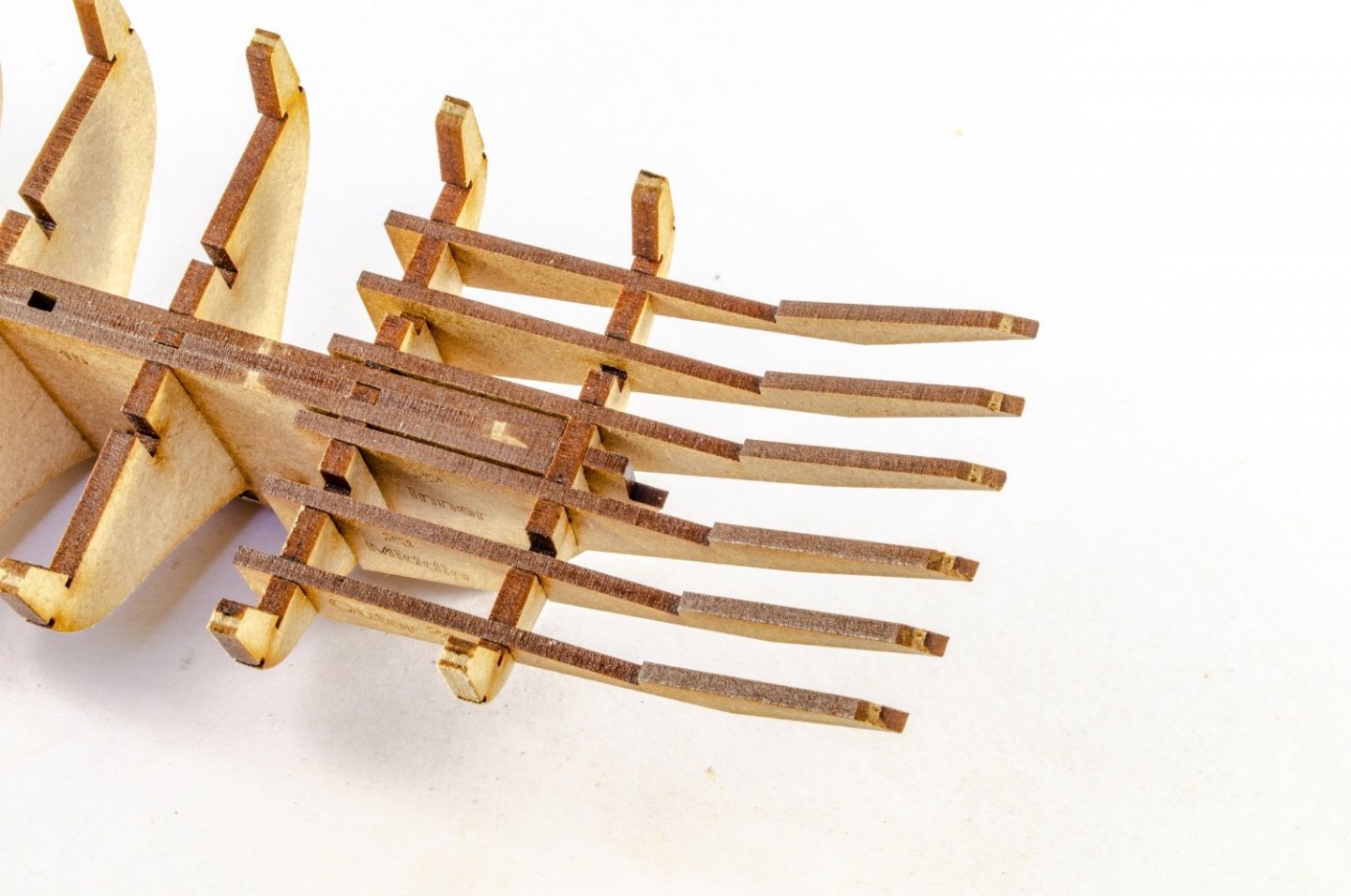
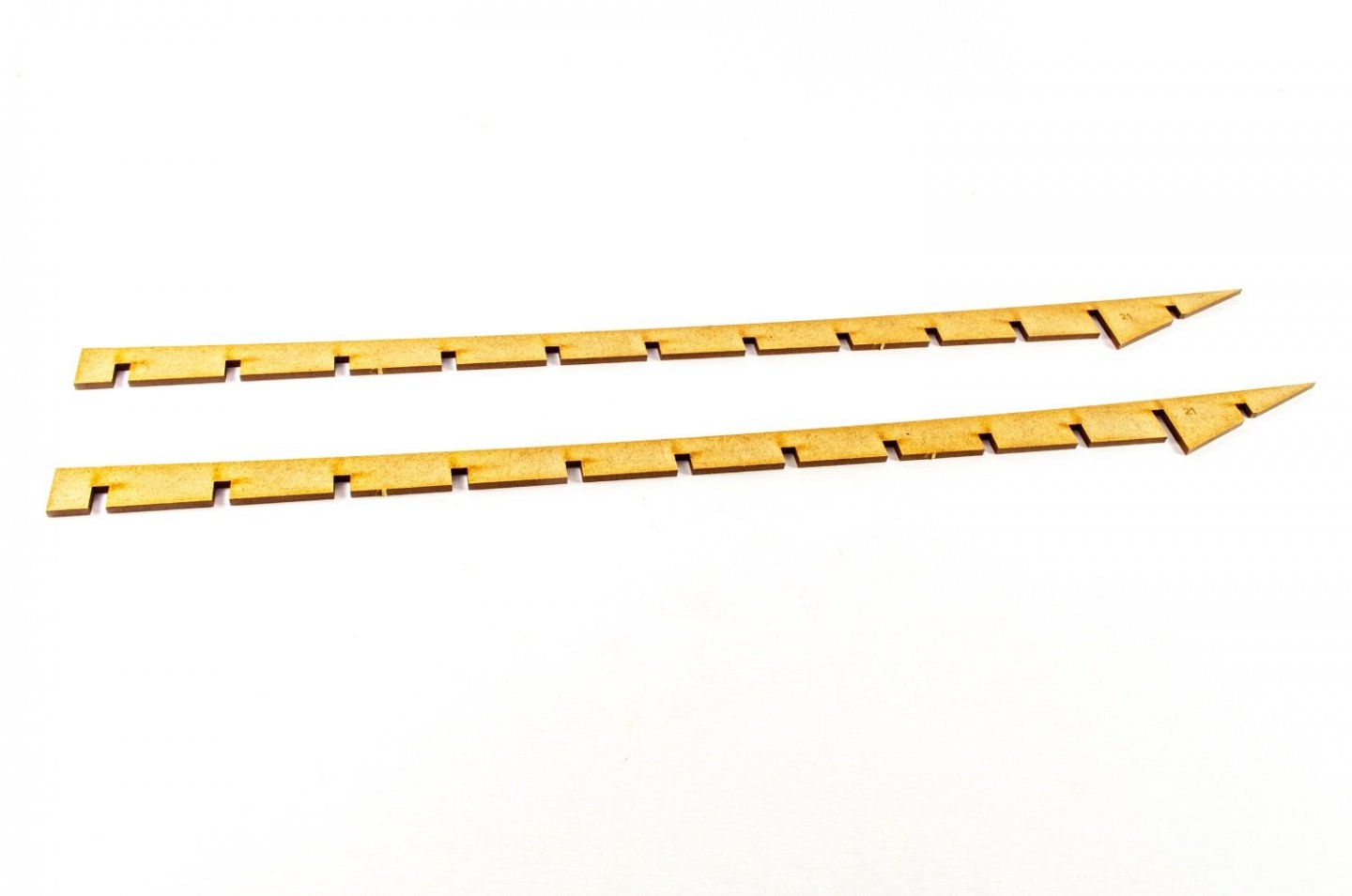
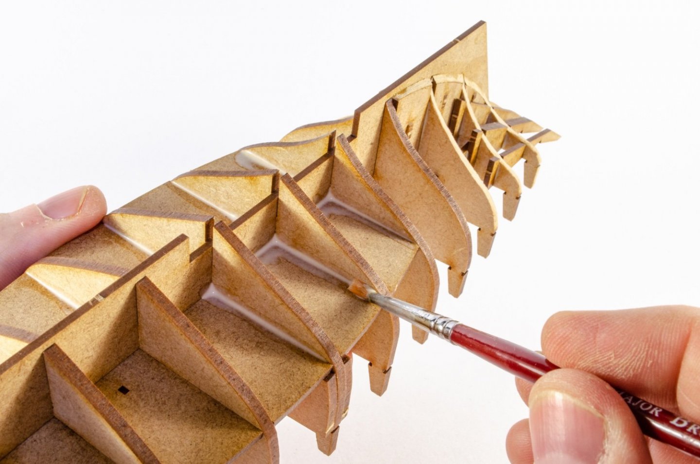
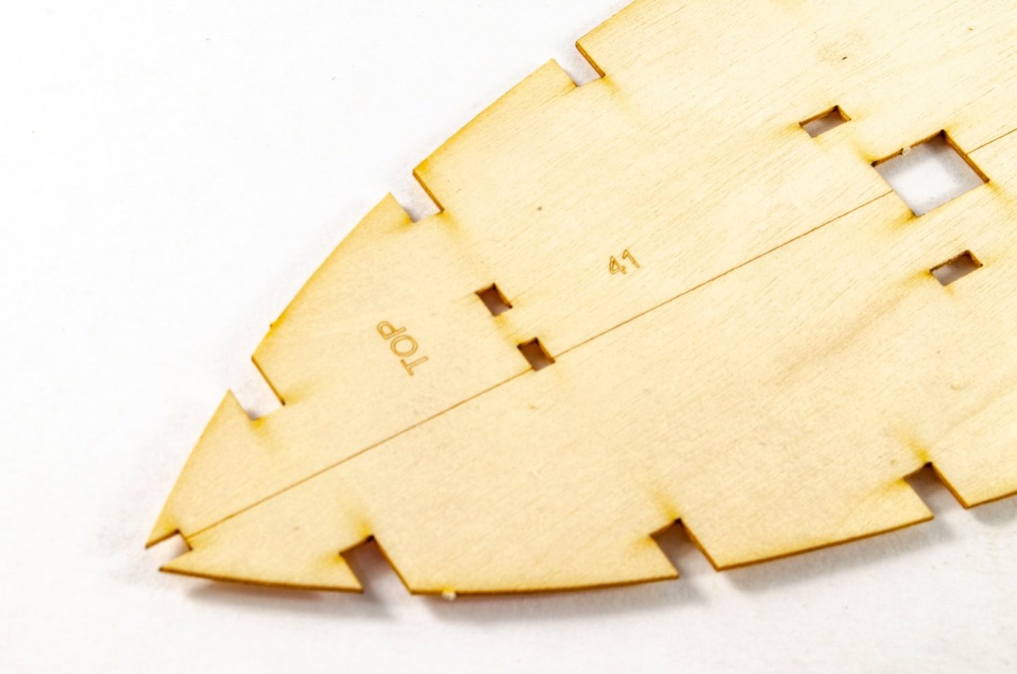
Fairing patterns are now added for the stern. Again, these are pre-bevelled, glue up against the keel, and are aligned with pegs. The stern timbers are now added. There are three sets of these which are clearly identified (INNER, MIDDLE, OUTER) and they slot into the bulkheads as seen here. To help brace the bulkheads, lock in alignment and create rigidity, two longitudinal beams are added. Bulkhead 7 (midships) is padded out with a part either side. This is there to help the modeller with the two-part inner bulwarks, and also aids the first layer of planking which can be split into sections to make it easier for the beginner. Slightly diluted glue is now brushed into the frames and then left to thoroughly dry. I quite like this approach. It doesn't compromise and strength in the frame, and caters well towards the many slots that the design has. The ply 'under-deck' is now to be added, noting that there is a top side to this!


- 16 replies
-
- 4
-
-
- Ranger
- Vanguard Models
- (and 2 more)