


thibaultron
-
Posts
2,951 -
Joined
-
Last visited
Content Type
Profiles
Forums
Gallery
Events
Everything posted by thibaultron
-
 I'll be following. I have the ME kit and the Sterling one. I'm planning to build the Sterling just to show the schooner arrangement, not as a detailed model.
 -
Currently on Ebay, there is a seller who has just started listing accessories for the saw. He has several, including a better rip fence, miter gauge, and a back plate. I ordered the fence and the plate. I contacted him, and he plans to keep listing new items. He has been making them for several years. Presently he has the fence, plate and gauge at least available.
-
Will be restating soon. I just finished refurbishing my shop to the point I can start working in it, and found the wood I bought for the mast and boom, that had been packed away.
-
Would the plastic frame allow you to put the unfaired frames in and then sand the outside fair after everything is assembled? For me that might be a better way than risking damaging a frame by over sanding beforehand.
-
The move from China is already happening. Many manufactures are moving to India, and other SW Asian countries.
-
I signed up!
-
Not that brand, but a similar one, for about the same price.
-
Thanks, everyone, for all the links!
-
Yes, thanks!
-
I too, would like to know if there is a US distributor of the Ask tools.
-
My Spray Booth Construction
thibaultron replied to thibaultron's topic in Modeling tools and Workshop Equipment
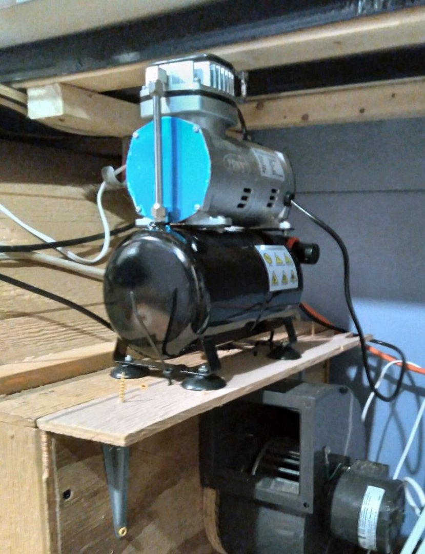
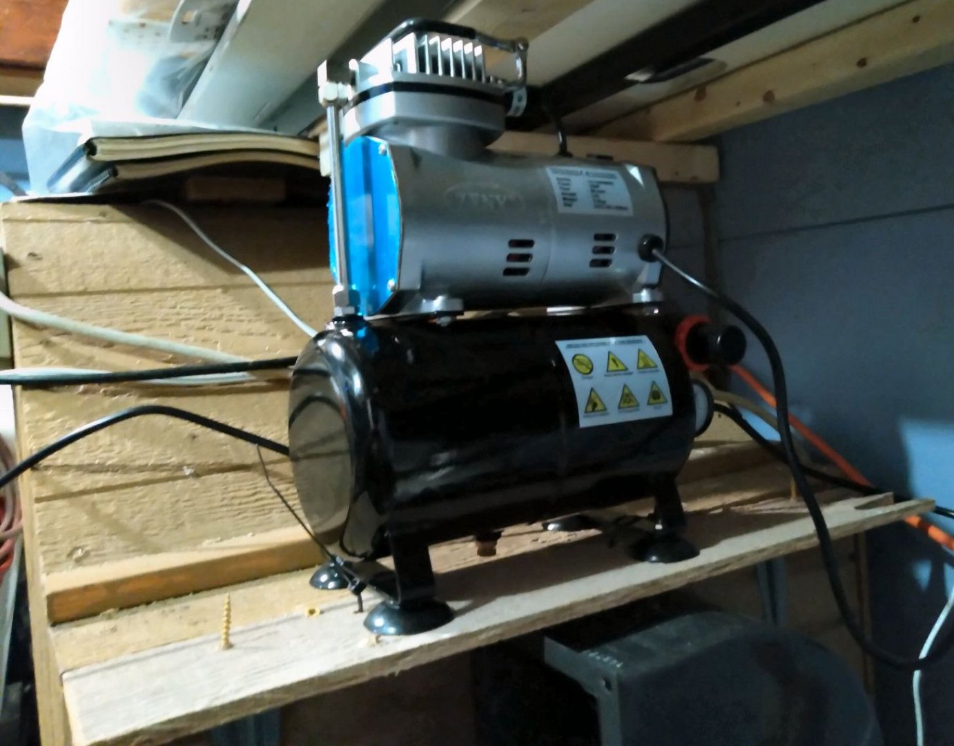
Part 14 Today I installed a small shelf on the back of my spray booth, to mount my new dedicated airbrush compressor. I screwed a couple small shelf brackets to the back of the booth, and temporarily screwed on a small shelf on the brackets. Using this piece, also, means that I have completely used the entire 4X8 sheet of plywood I built the booth from, no waste! I have to buy some small machine screws tomorrow, to finish bolting the shelf in place. I drilled holes in the shelf on either side of the compressor legs for wire ties to hold it in place, while still allowing the rubber feet to dampen vibration. When I install the machine screws, I'll add a couple of eyelets in the main spray booth housing for two additional wire ties at the "forward" edge of the legs. It "Just" slides under the shelf above it, but as I'm going to be moving the work bench and spray booth in the near future, this is not a problem. Sorry the photos are a little out of focus, I didn't realize the flash was turned off on my phone.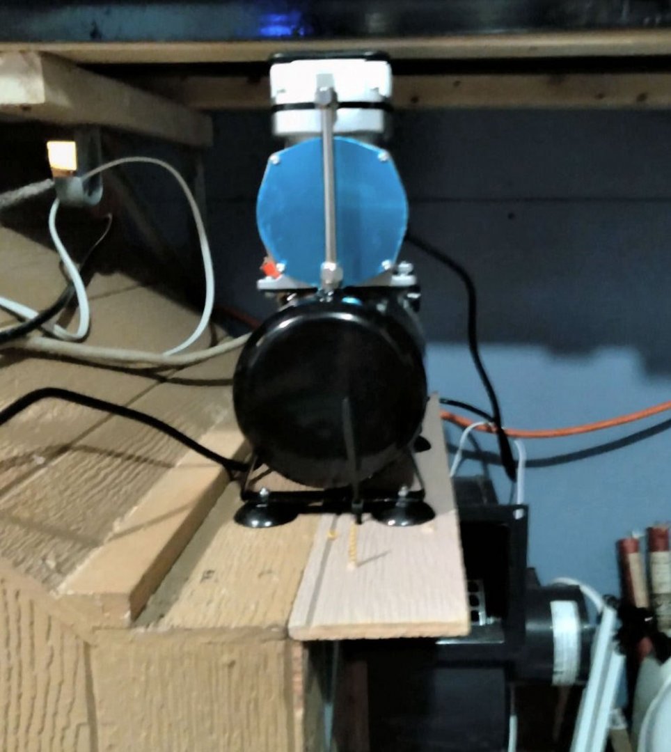
-
I'd forgotten about that one.
-
Most of the cross section kits are highly inaccurate. These generally have the wrong number of decks depicted, for starters! The only two accurate ones I know of, are the new Model Expo USS Constitution cross section, and CAFs HMS Granado cross section.
-
Where can I get TINY letters for my ship?
thibaultron replied to Brenticus's topic in Plastic model kits
Here is a video given at a virtual Model Railroad clinic recently, on using the Cricut machine. -
Another video by Barbatos Rex, on Decal Setting solutions. This is a comparison of several brands of decal setting and settling solutions that mat be of interest. I learned a lot (mostly about how I've been doing it wrong)! And Yes, there were a couple winners.
-
kit review 1:48 HMS Granado ‘Cross Section’
thibaultron replied to James H's topic in REVIEWS: Model kits
Thanks! -
kit review 1:48 HMS Granado ‘Cross Section’
thibaultron replied to James H's topic in REVIEWS: Model kits
Chuck: I count 6 VTHokiEE Me dvm27 James H Tim Murphy Canute -
kit review 1:48 HMS Granado ‘Cross Section’
thibaultron replied to James H's topic in REVIEWS: Model kits
Just ordered this kit. I'd like to join a group build thread also! -
Where can I get TINY letters for my ship?
thibaultron replied to Brenticus's topic in Plastic model kits
The Cricut Explore can handle up to about 3/64ths basswood. It has trouble with interior cuts, like for a window opening. It has a pivoting blade so to insure the corner is cut "square" it cuts past the corner, then back at an angle to start on the other section. This leaves a small triangle extra cut out at the corner. Not bad if you will be adding a trim piece to frame the opening, but a pain if you want just the square opening. The new Cricut maker can do at least 1/16th bass, and has a gear driven knife for square corner cuts. I have had difficulty going from CAD to the machine, but have not had time lately to revisit it. If you are trying to cut an existing card pattern (As in a cardstock building, or file download (ship card model, where you want to print out the file and cut to the printed patterns) you are limited to I think 6X8 inch maximum output size. This is because their proprietary software Design Space uses your browser software as a print engine, and you are limited (for unspecified reasons). Clipart and Line drawings can use the full size sheet up to the largest cutting pad size. Remember though that the cutting pads are sticky to hold the material, so small delicate parts can break or rip when you go to remove them. As I say I've not had time recently to play with my Explore machine more. -
but I was able to hone the tube out enough to rune the wires up the tube. Yes, a little magic always helps!😀 Sounds like one of the steps in Project Development. "Then a miracle occurs."
-
Thanks for the pencil recommendation. I have a 12 pack on my Amazon Wishlist, for next week.
-
Chappell's fishing schooners book?
-
Lead us not into temptation....
-
I ordered a couple books from them, and they arrived in a reasonable time. To add to the prior post about the US mail delays. I just received a photo that was mailed out 12/12, almost 7 weeks, so be patient, it likely is not their fault.
-
I'm sure none of the rest of us is addicted to collecting! 😆 I figured out that if I build one ship per month I'll have to live to 81, just to complete the ship kits I have! This doesn't count trains, planes, and automobile models. But at least I have an interesting selection to choose from!


