


thibaultron
-
Posts
2,951 -
Joined
-
Last visited
Content Type
Profiles
Forums
Gallery
Events
Everything posted by thibaultron
-

What's wrong with Artesania Latina Constellation?
thibaultron replied to Antti's topic in Wood ship model kits
The AL kit is actually a very good represenation of how the ship looked in Baltimore before the 80s, when they corrected it to the 1855 original setup. So AL can not be fully blamed, they designed it as it actually existed then. -
I'll look, thanks.
-
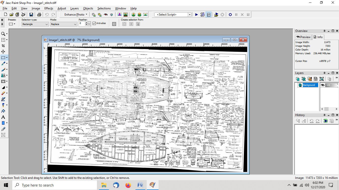
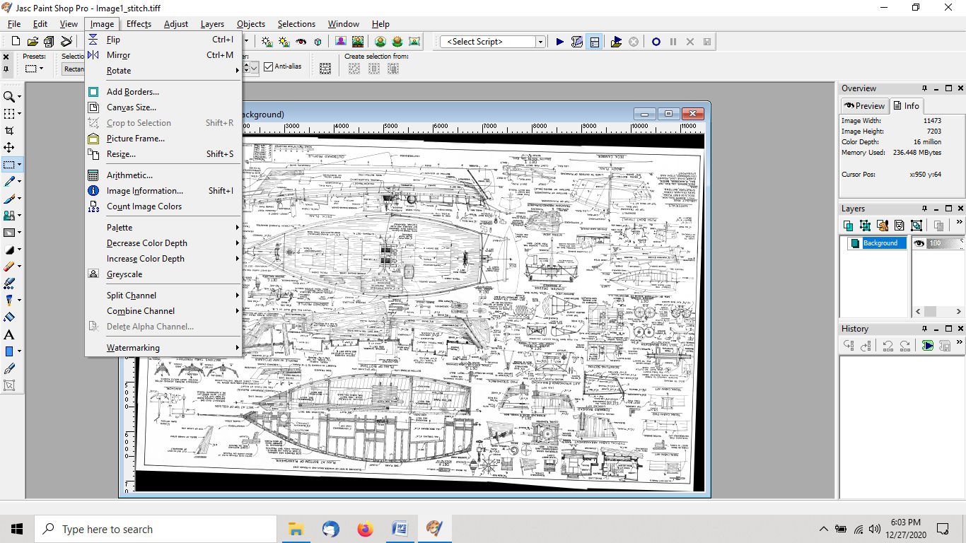
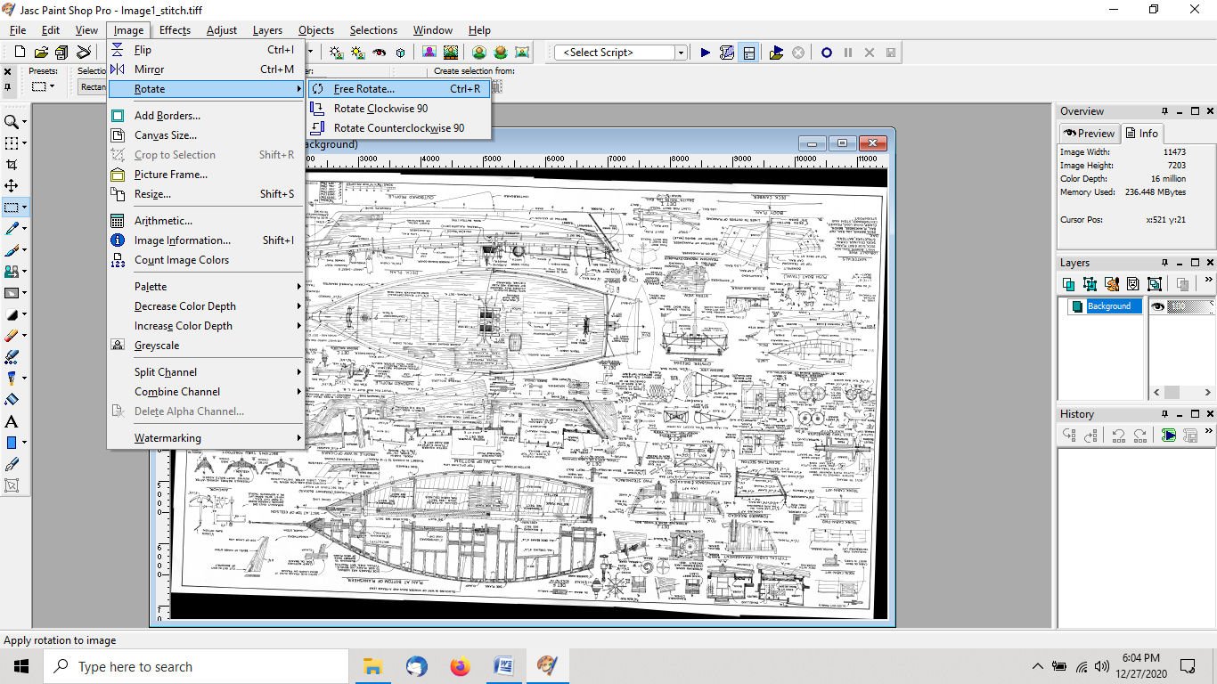
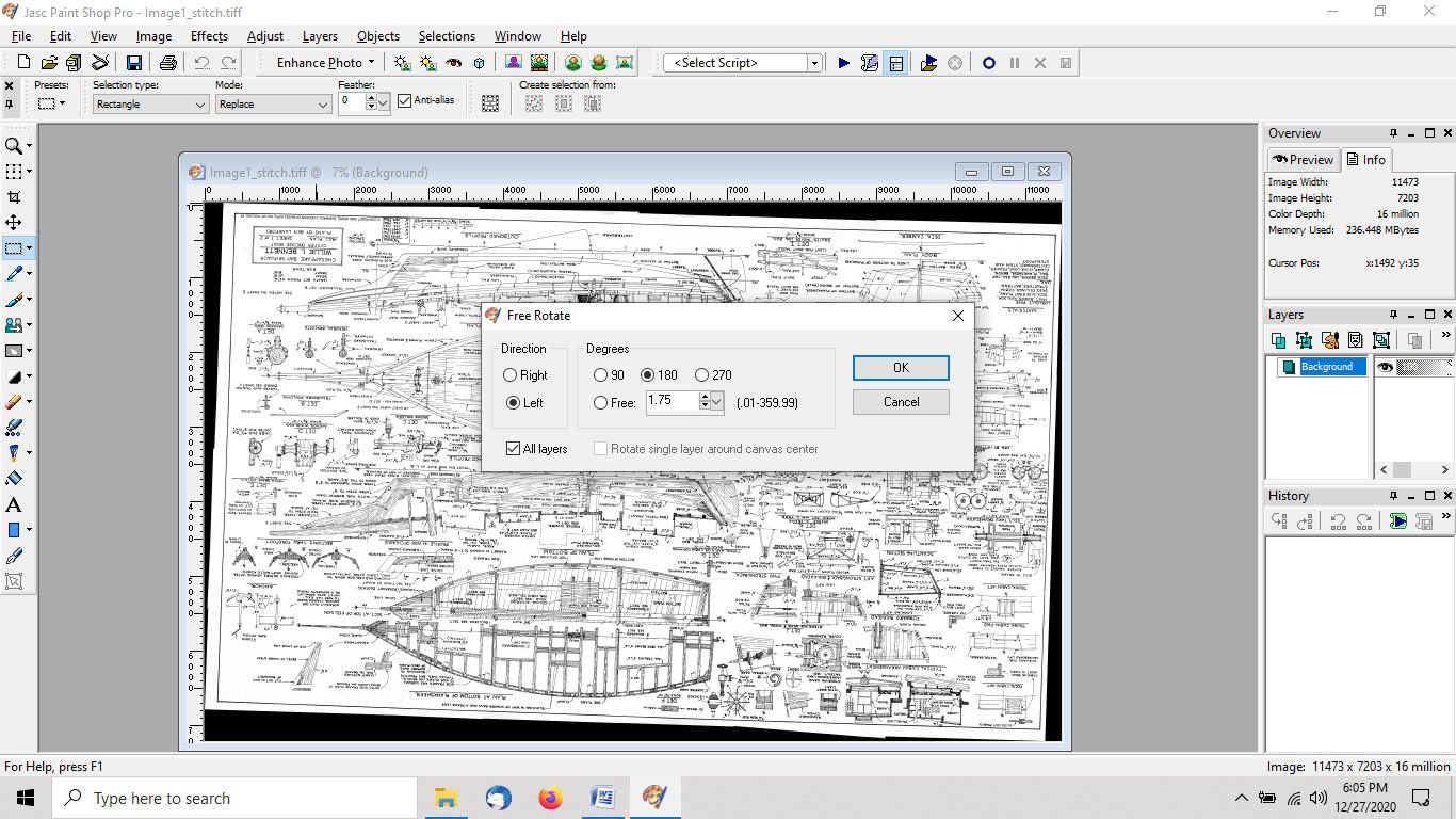
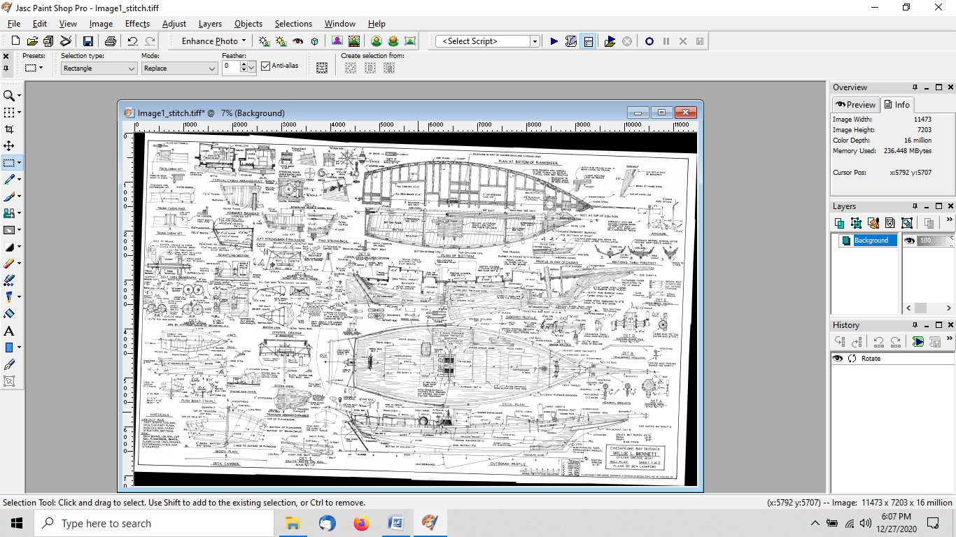
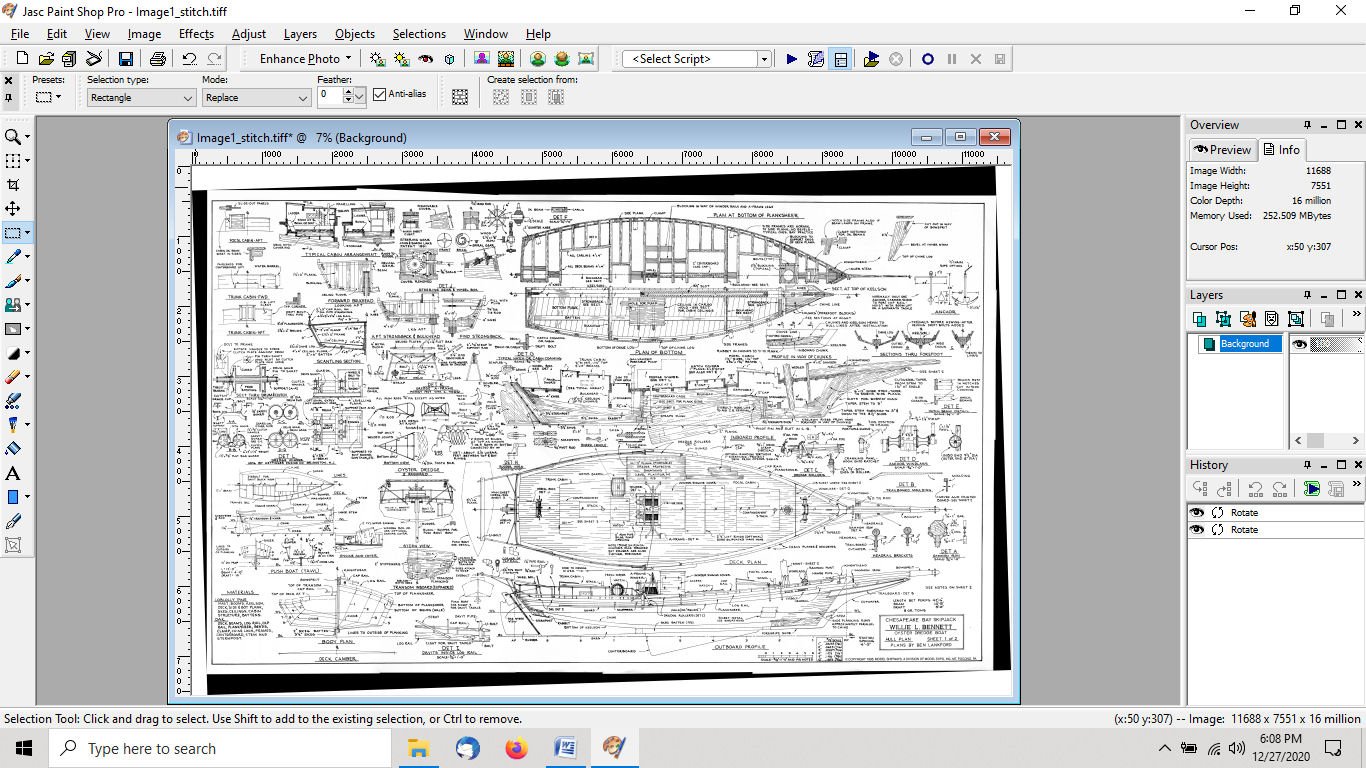
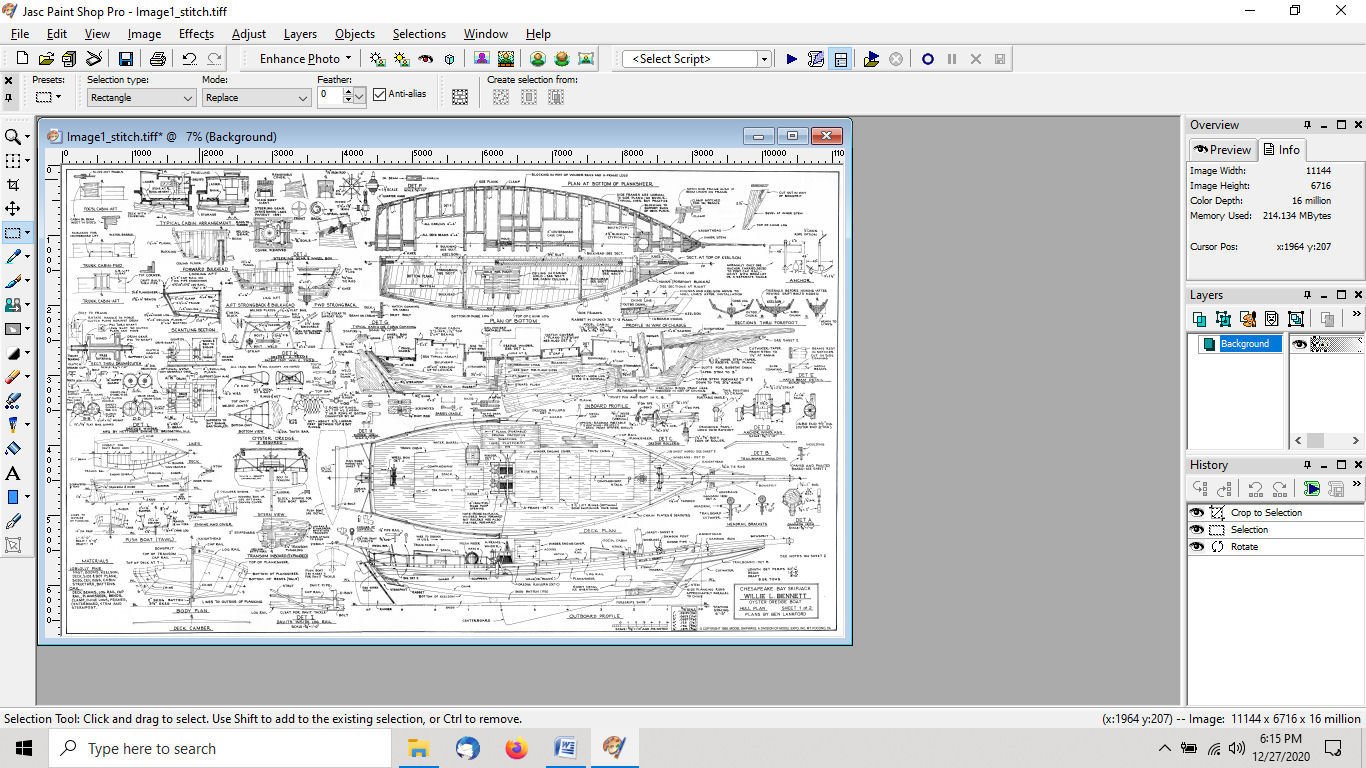
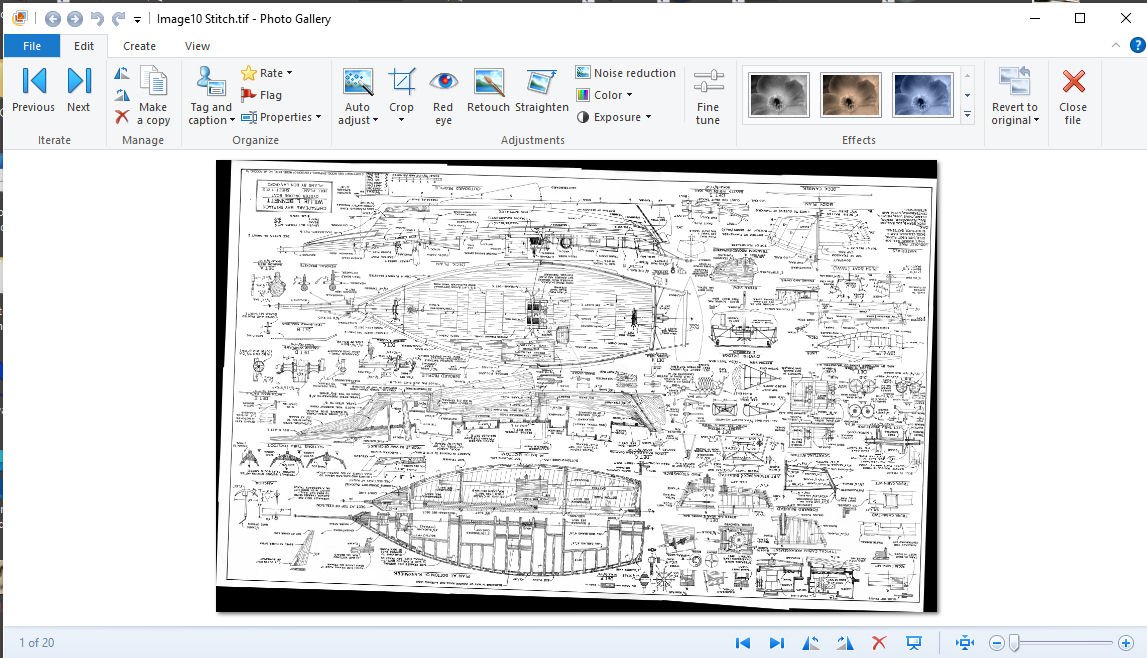
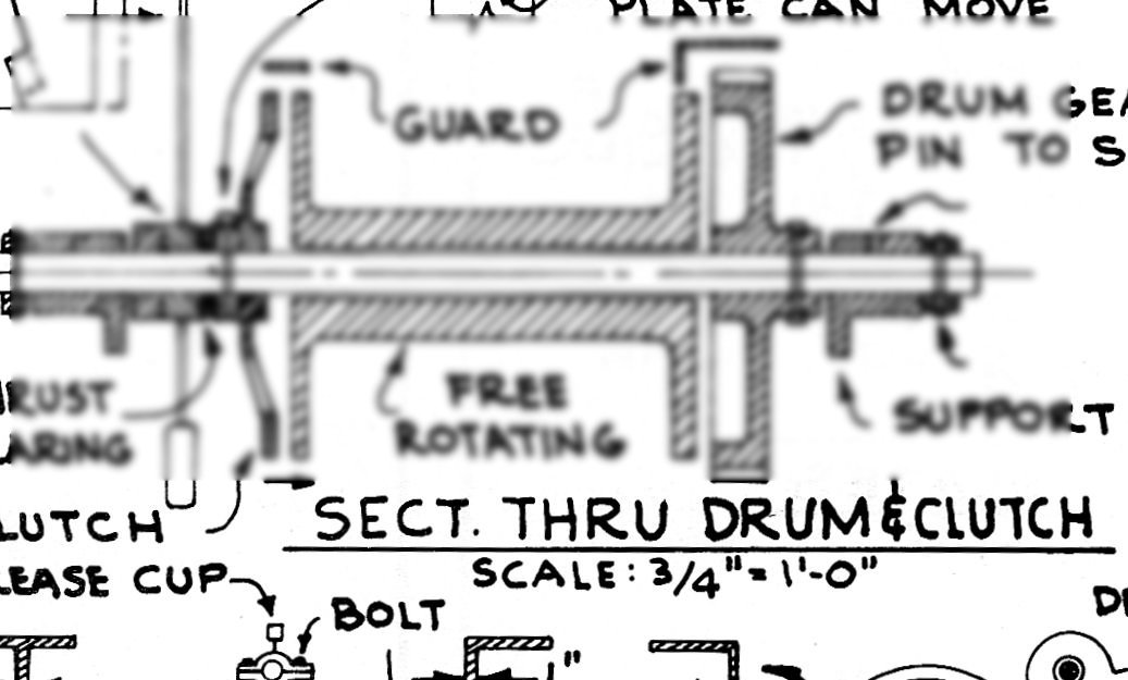
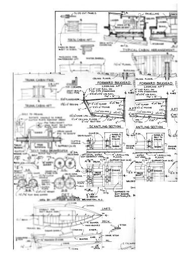
Part 03 Then close the program, then when it has finished, select “Discard Project”. Now you can use a graphics editor to finalize the panorama. As another note: ICE saves the composite as a compressed .TIF file. So the first thing you should do is open it with your graphics editor, and save it as an uncompressed TIF file, before you further work on it. I’ll show an example using my very old copy of Paint Shop Pro 9. No explanation, other than the pictures, as your program will be different. I then rotated it to level. In this case 1.75 degrees left. Yes, I cheated and had previously used my CAD program to find that angle. Then cropped it Now I have a nice composited digital plan file. Not all the drawings inside the plan are square with the border, so use an internal drawing line as your reference to “level” the whole drawing. This was the case with this plan, so I used one of the center lines. Check several center or baselines to make sure the drawing is not bowed or otherwise not correct. On this drawing the deck center line is bowed (by about 1”) but all the other base and center lines are straight to within the width of the drawn line. The original drawing must have this error, and it is not due to the compositing.
-
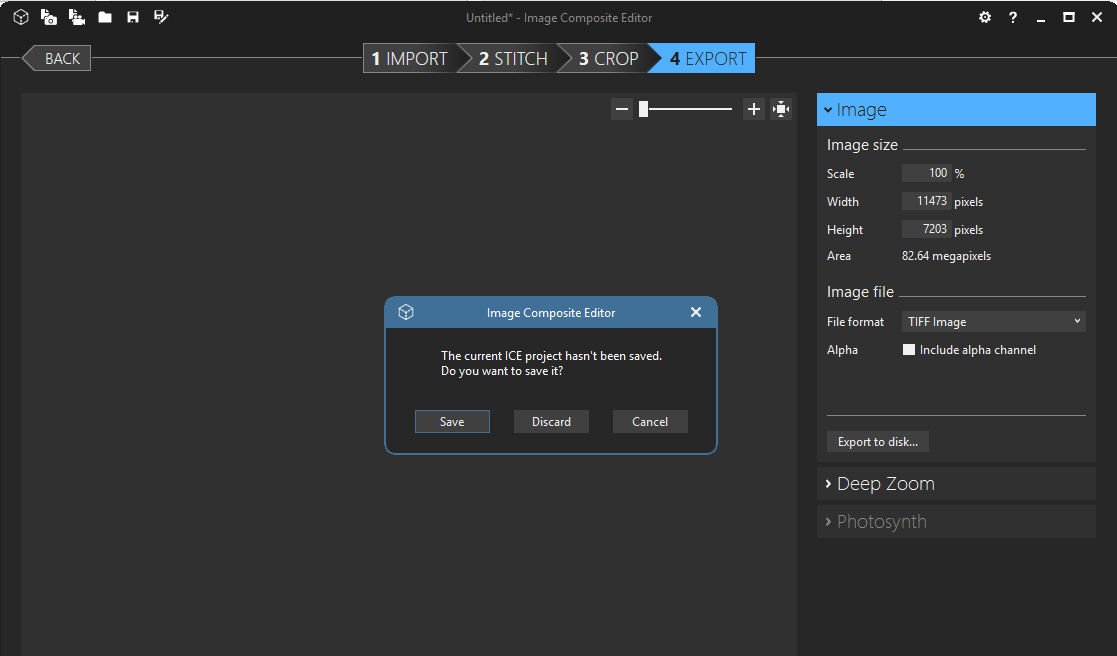
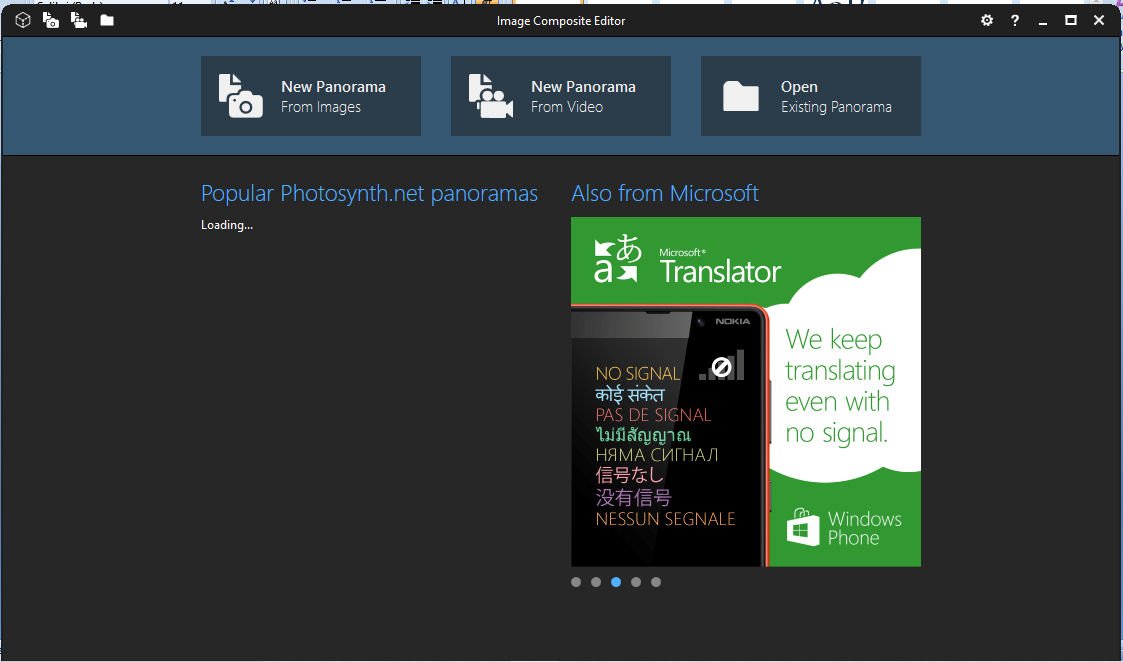
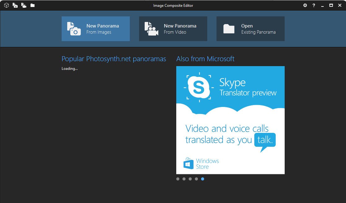
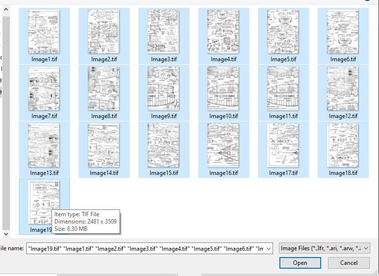
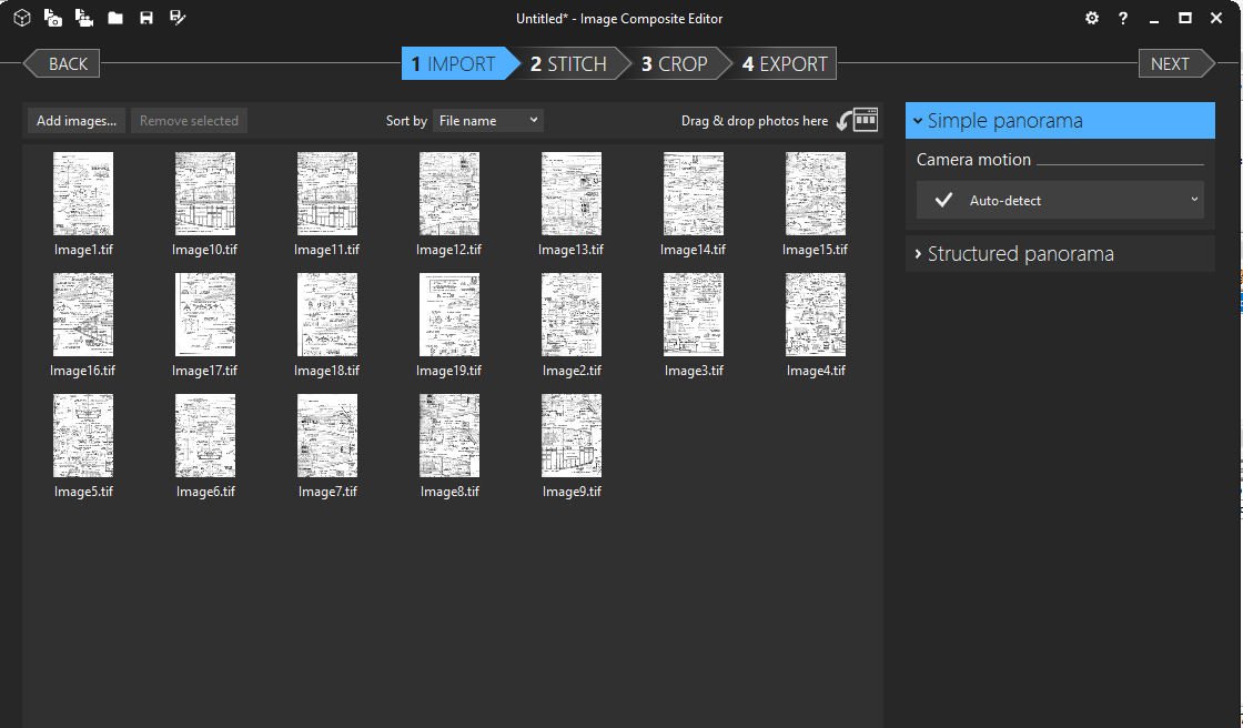
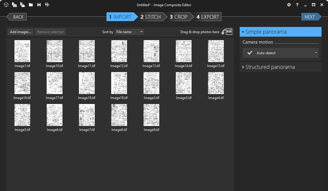
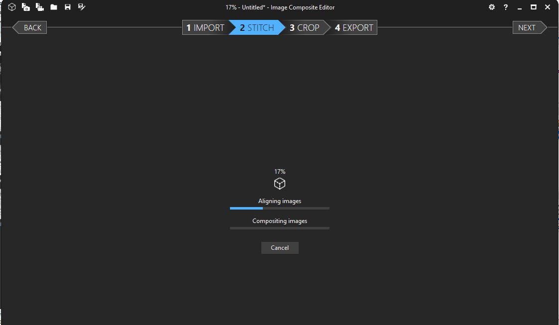
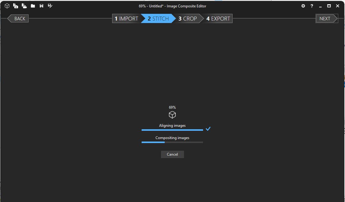
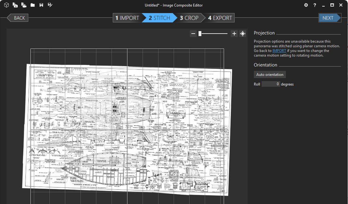
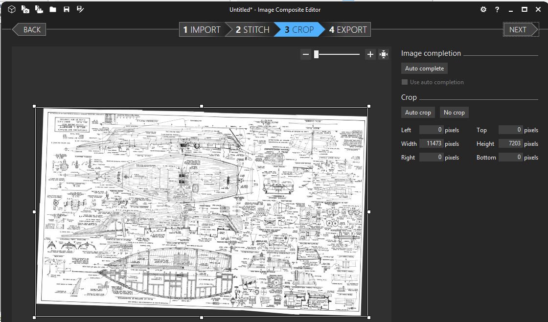
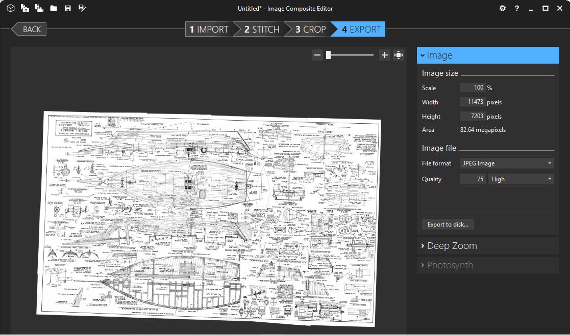
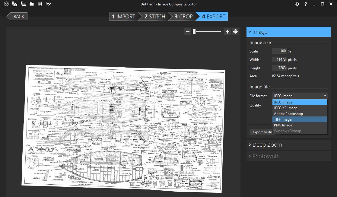
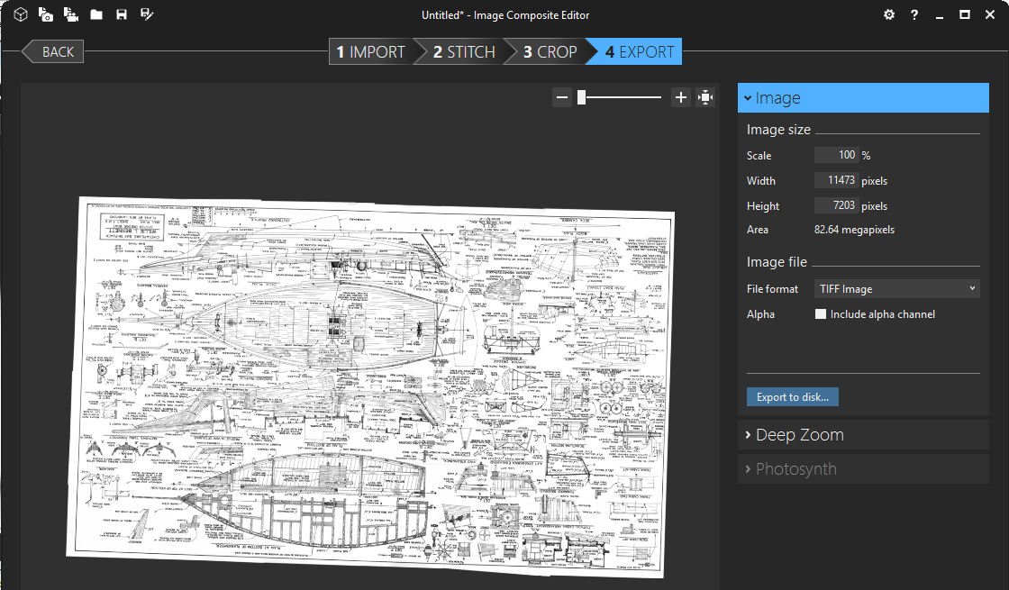
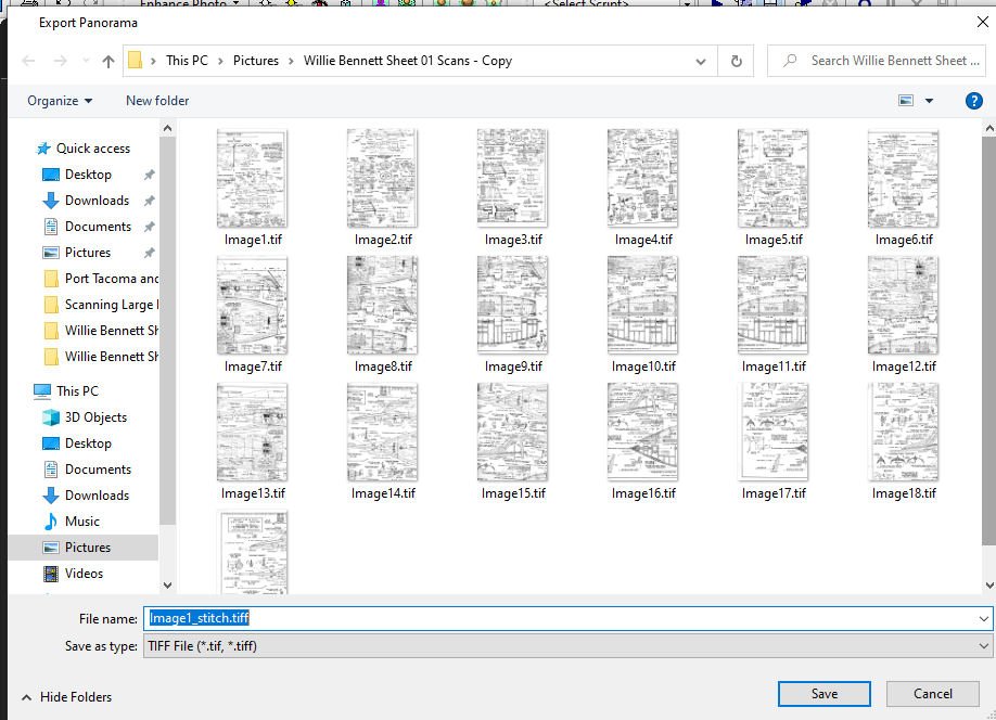
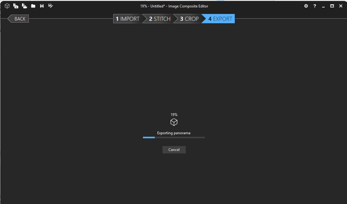
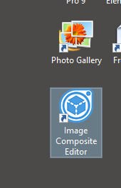
Part 02 Select “Save”, and the file will be saved, when that is done, the finished file will be displayed. Don’t worry that it is not square in the “Frame”, you can fix later with a graphics program. In this case it is also upside down. That must have been how I scanned it, or at least how Gallery saw the best way to combine the files. In any case, copy the stitched file to your original directory. I generally delete the directory file in “Pictures”, just to save disk space. ICE is a bit simpler. Note: You can use any directory with ICE. Start ICE This screen will be displayed Select “New Panorama From Images”. Go to your directory and select the images. This screen will be displayed, with your images displayed. Select “Next” The process then starts. The process continues. The finished panorama is displayed. Select “Next” again and the “Crop” screen is displayed. Select “Next” and the “Save Image“ Screen will be displayed. In the “Image” area select the box in the “Image Format” section, then “TIFF”. Then select “Export to disk”. The file will be saved. The save screen will be displayed, notice that ICE also supplies a name, if you want to use it. Select “Save” and the file will be saved.
-
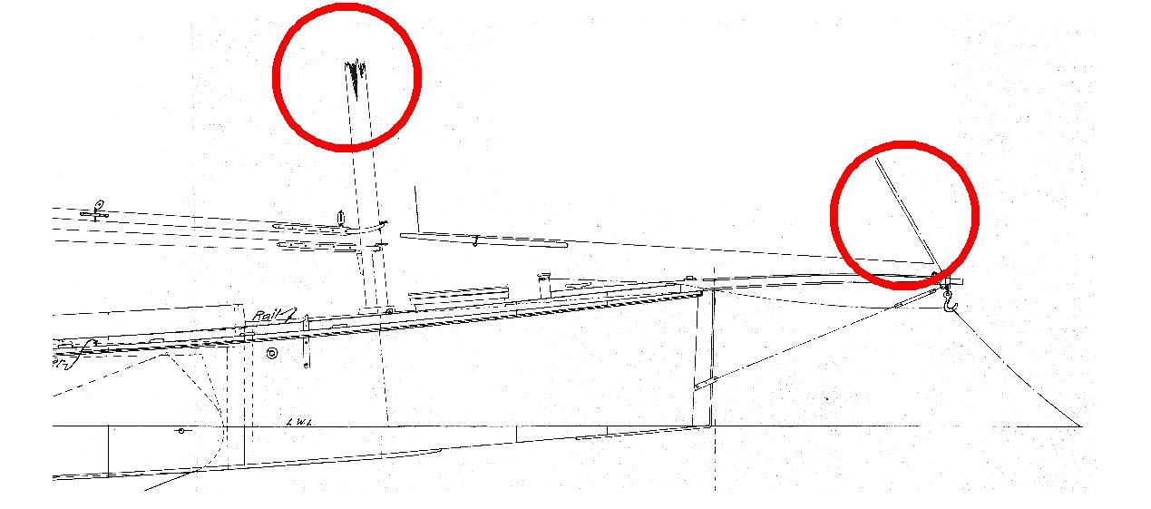
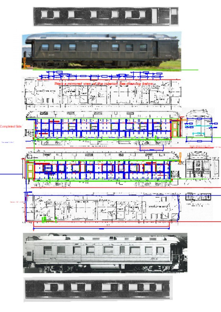
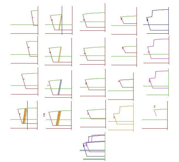
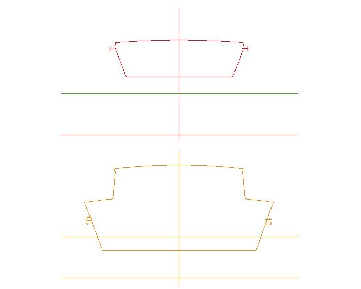
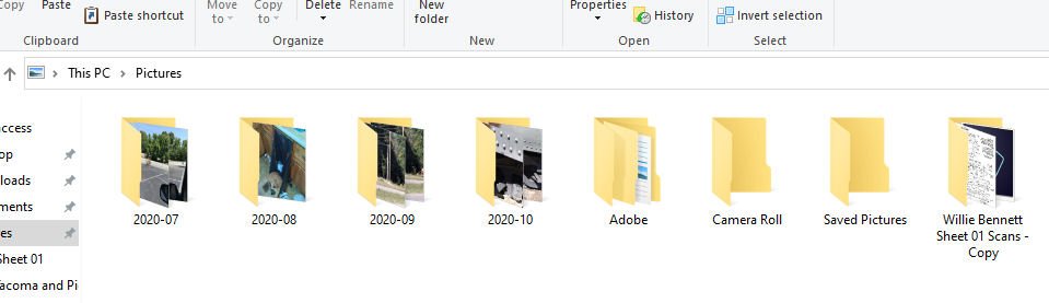
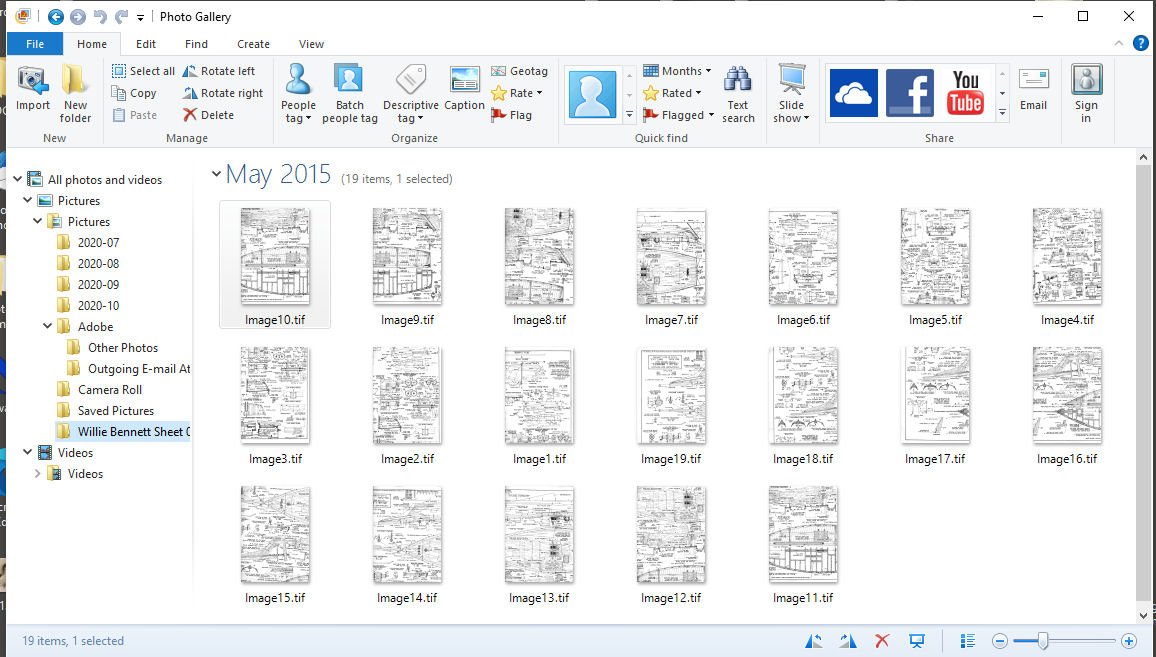
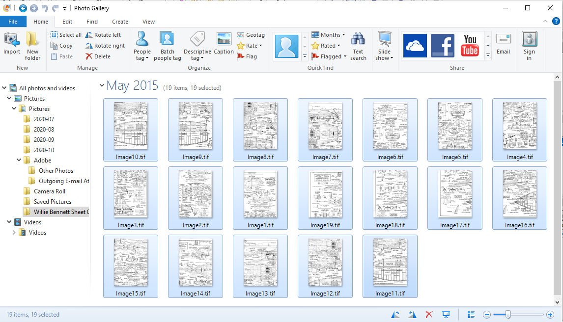
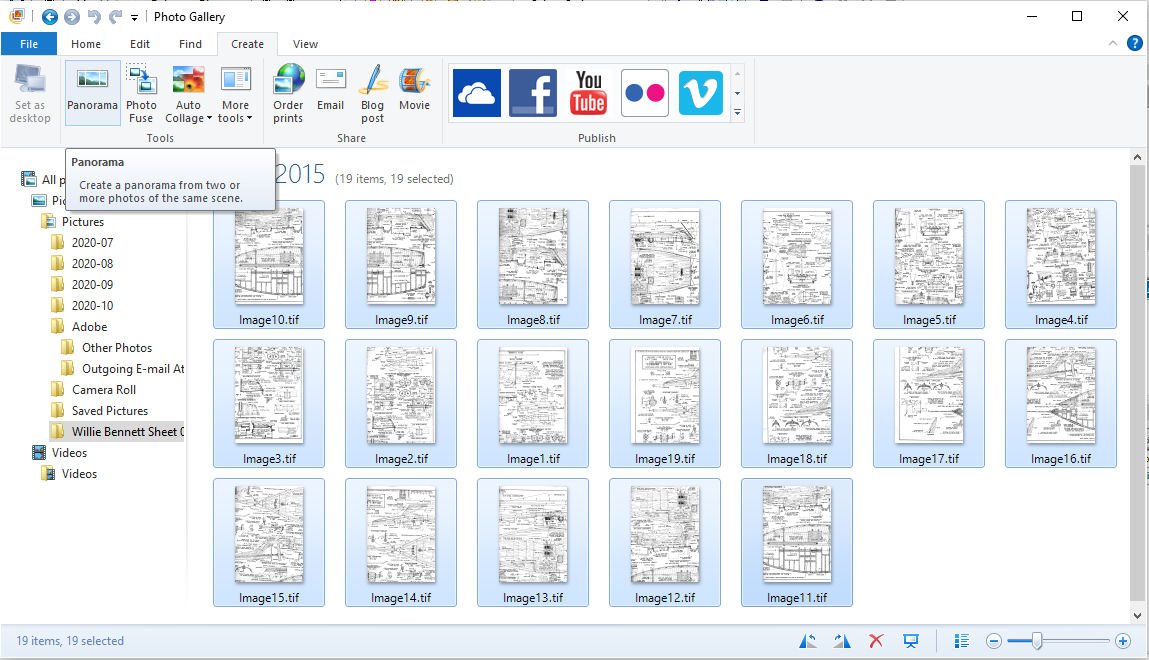
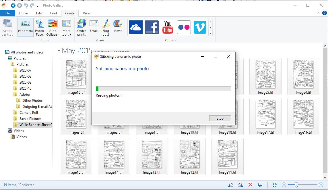
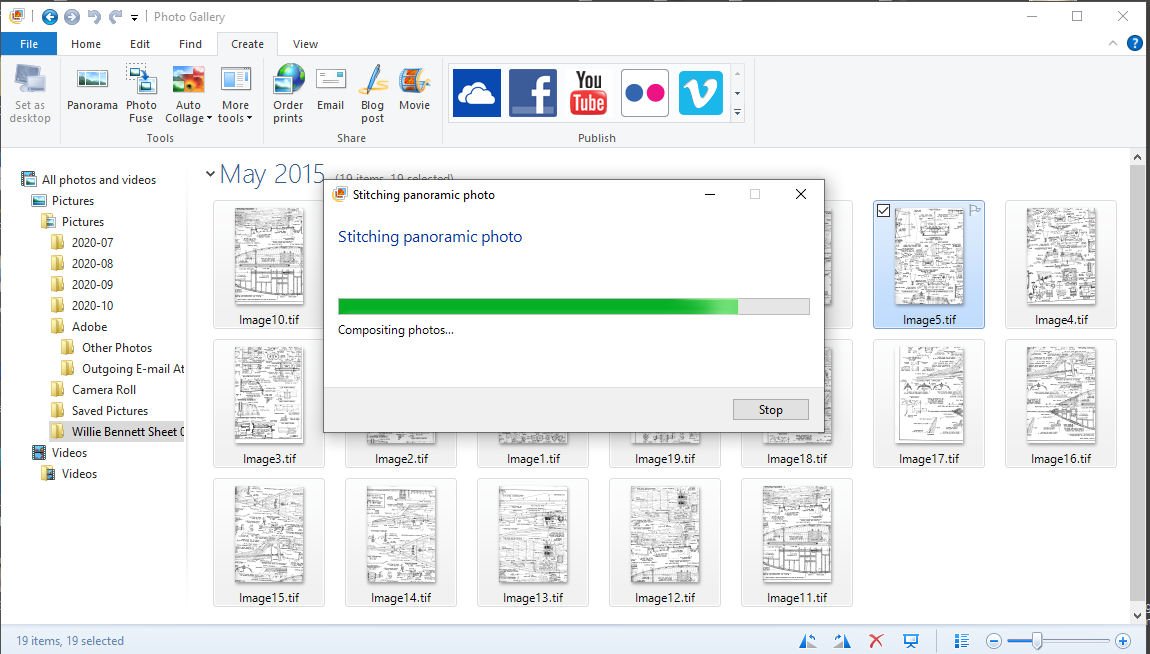
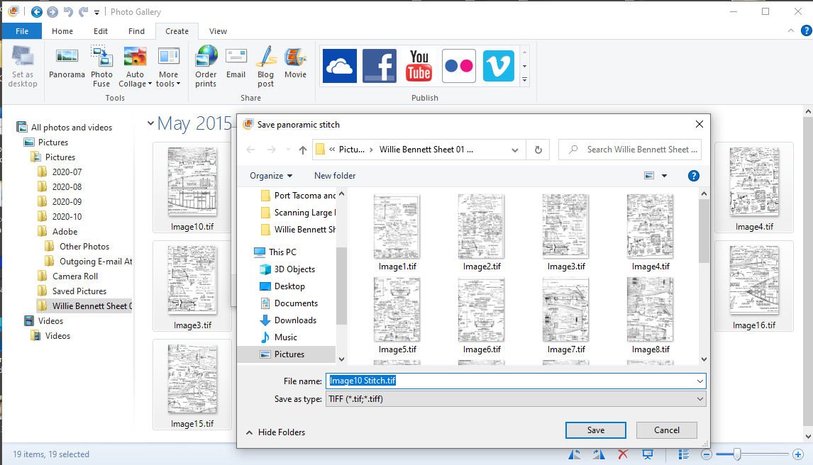
Part 01 Most of us don’t have very large format scanners at home. One that could scan a large plan sheet. Nor do we necessarily have even paid access (or the money for same) to a commercial one. Thus we are stuck will our standard 8 ½ by 11+ scanner. As some will note, scanning in the plans can add distortion from the scanner itself, as can the process of combining them. If you are careful to check for this, some corrections can be made using a photo editing program. For most of us, any distortions are quite small, and probably less than a real wooden ship varied from the original plans, just due to the fact wood is a flexible and changing media and measurements were not all that precise and the ship could settle during framing and construction. You, of course, can redraw the plans by hand, or use the drawing directly to build your model, but many times CADing the plans works as well or better. There is a way to scan in a large sheet one section at a time and combine them into a single scanned sheet. Why would you need a complete scan of a sheet if you have the original? There could be several reasons. Here are my typical ones. 1. I want to rescale the drawing. 2. There are larger scale detail drawings on the same plans sheet, and you want to make scale drawings as templates. For instance. The plans for Model Expos’ Willie Bennett, has 1/32nd scale main drawings, and 1/16th scale detail drawings on the same sheet. 3. There are many parts on the model that are copies of the same part, (blocks, anti-aircraft guns, cleats) that can easily be copied and moved with CAD. 4. You want to print a copy of a section, and build the model on it rather than the original plans. 5. There is missing information on the plans. A section that has been ripped out and lost, too few frames drawn. I have a drawing I’m working on from an “Out Of Production” kit (manufacturer is no longer in business) where the fore frame line drawings are close and the stern lines completely factious, I assume to keep someone from building the boat from only the plans. The bulkheads were precut in the kit. On another boat I’m drawing, the masts are shown broken off just above deck, with no spar information supplied. Using the short length of fore stay shown, and an old woodcut, I found after a couple years of searching, I was able to determine the mast length for both the fore and main masts. The woodcut showed that the foremast ended just above the fore stay fitting. Not a very hard example, but the plan sheet was too small to draw the masts or sail plan, so CAD was helpful. 6. You need to check some of the drawing against anther area, and want to trace it out in CAD. A case I run into frequently is the frame lines not matching the body lines, or offset table. 7. The various views differ. I’m drawing up a Santa Fe business passenger car, for 3D printing. After scanning in the drawing and starting to CAD I found that the overhead and two side views in the original drawing were slightly different lengths (yes all 3 views differed by several inches). In the case of this drawing, several of the dimensions given were also wrong! 8. You want to compare the plans to photographs (as above) of the original prototype. Again with the train car above, the side views had the windows slightly incorrectly placed. Also using the photographs in direct comparison I was able to correctly place all of the several hundred rivets, precisely. The pictures at the very top and bottom are the sides for a version of the car, after AC was added in the 50s. Those pictures are the sides from a kit. 9. You want to make bulkhead drawings from the offset or frame drawings. It is easy to copy, mirror the one side and place the “other” side once one is done. Here is an simple example: 10. You need to have CAD files for a laser cutter, or 3D printer. Anyway, on to how to do it. 1. Scan the drawing in sections, allowing an inch or 2 of overlap (top bottom and sides). a. Shown is an example of two overlapped scans. As you can see, both scans have hefty amount of overlap. The overlap shown is far more than needed, but that is alright. 2. Save each scan as a separate file. It is best to save them as .TIF or .TIFF files, with no compression. Many other types, such as .JPG or .JPEG, compress the file EACH time you save it! This causes the final file, after several iterations, to be quite blurry. 3. Now there are two ways to get the scans into one picture for your CAD or graphics file. a. You can lay each picture onto a larger graphic editor blank “Canvas”, aligning each by hand. This can be difficult, because as you move the original around for the scans, you will rotate it slightly as it is moved. This means you also have to custom rotate each pane to a common angle, as well as line them up. i. This is easier if you are lining them up in a CAD program, as long as each is prerotated using the CADs ability to measure angles. After finding how much the pane is off by, use the graphics editor to correct the pane angle. You can then place all the scans in the CAD window, mark common points and move the panes to mate at those points. I can give examples of this using DesignCAD, if you want, later. b. You can use a Graphics Editor program to combine them automatically (Called a Panorama or Composite). Most graphics programs can do this with photographs, but many not so well with drawings. I have had poor luck with Photoshop and GIMP. The best two I have found are Microsoft Live Elements (Photo Gallery) and Microsoft ICE (Image Composite Editor). Both are free. i. The Live Elements app Photo Gallery can be used to create a panorama from drawing scans. This is a 32bit program and can stumble on larger files or a large number of files. Note that, with Gallery, the files must be in the User’s “Pictures” directory. MS no longer supports this program, and has taken it off their site, but a full download is available at; https://web.archive.org/web/20170112124505/http://wl.dlservice.microsoft.com/download/C/1/B/C1BA42D6-6A50-4A4A-90E5-FA9347E9360C/en/wlsetup-all.exe ii. The ICE is a free, current, download and is 64bit (There is no telling with MS, how long they will support it, though, as with Live Elements) At: https://www.microsoft.com/en-us/download/details.aspx?id=52459 c. Be sure to carefully check the final “Stitched” drawing, things can and have gone wrong with my files. i. Sometimes the process just fails spectacularly. ii. Sometimes the panorama is distorted. d. If difficulties arise try: i. Checking that your overlap is OK. ii. Make sure that all the images are correctly oriented to each other, all right side up, or all upside down. iii. Perhaps stitch the scans in smaller groups, then stitch the larger groups together. iv. Try a different program. Here are some examples with the two programs. Photo Gallery Note make a copy of the directory you want to combine the pictures in, in that same directory. Sometimes Gallery modifies the files in the original directory also! Then copy the “Copy” directory to “Pictures”. Now that the directory is in Pictures, Start Photo Gallery, and select the directory you will be using. Then select all the images you want to combine Select “Create” Then “Panorama” The program will then start the process. And proceed to the next step. When it is done (if it competes, otherwise you will get an Error message), you are asked to save the Stitched file. Note a name is generated for the panorama, change it if you like.


-
Drafting
thibaultron replied to mangulator63's topic in CAD and 3D Modelling/Drafting Plans with Software
About the comment about the servers going down, just before a deadline. True, but I have a story about regular drafting. Many years ago at a company I worked for a draftsman was working late to finish a batch of drawings. He put the rolled up drawings in his waste basket, as he finished them, to save time. (I will admit that wasn't the best way to store them before filing.) That was fine until he went to the bathroom, and came back to find that the janitors had come through and emptied the trash! The drawings were destroyed before he found the janitors. He spent the entire weekend redrawing them. -
Drafting
thibaultron replied to mangulator63's topic in CAD and 3D Modelling/Drafting Plans with Software
Wow! That is a beautiful model! -
Drafting
thibaultron replied to mangulator63's topic in CAD and 3D Modelling/Drafting Plans with Software
The CAD program I was given was DesignCAD, and it is still my main one. I've been doing 3D printing designs in SketchUp, the free version. I also took wood and metal shop in High School, and am another "fix it my self" type. -
Drafting
thibaultron replied to mangulator63's topic in CAD and 3D Modelling/Drafting Plans with Software
I took drafting in Junior, and Senior High School, and a couple in College(Electrical Engineering, the Mechanicals had a lot more). Drafted by circuit board designs by hand at work, until the Graphic CADs came along. Then went into software programing, as well as the computer hardware design. All that came into use, when I went into process control programing (program the control computer for factories, or in my case water treatment plants). Was given a copy of a CAD program, by a coworker, and have been using various new versions of that since 2D and 3D. On an side note: I had to take a year of typing, which I got a "D" in. I got up to 10 words a minute, but they insisted I go faster, and I completely lost it, and have been a two finger typer since then! 34 years as a two finger programmer! The advent of computer monitor based programming, vs. IBM Cards, was a great blessing to me! Much easier to go back and fix all those typos! When I got into the process control field, I fell in love with the graphics side of laying out the operator control screens (which still had a lot of underlying coding going on). . One boss came in and saw me coding, and exclaimed "Your a two finger typer?". Then she stopped and watched for a short time and said "But you're fast!" and left me alone. -
Same fate as the Pennsylvania.
-
HO scale, Santa Fe roughly 1935 to 1957, freelanced. the layout will be in three "sections" a port scene 2.5' x 12', an engine terminal with passenger car servicing 2.5 X 7.5, and a 12x 9.5 oval shelf layout with the modules 2 foot deep. At first the oval will be just a folded over double loop (making one circuit two times around) for running passenger trains while i watch. Later I will add sidings and industries to turn it into a switching layout also. I bought the Fast Tracks jigs so I can make my own turnouts for the engine terminal, and oval.
-
Yes, huge B-17 fan! I know, so many projects in the que. So far in the past month of being retired, I've gotten to spend maybe 1hour in the shop. I still have my Pyro skipjack and French fishing boat to complete, as well as an almost ready to paint Japanese houseboat. Then there is the whole building the train layout thing, though that is being held up due to lack of funds.
-
Nice! I have a vac form kit of a 1/72 B-17 YB, the first production model, and am terrified of it! Maybe some day I will tackle it. I have the complete series of 1/72 kits (all the A thru G variants), and would like to build the vac kit, when I finish those. I even have a card version kit of the prototype. Probably not enough years left to finish all of my stash.
-
A question for the moderators. If this was scaned and converted to a PDF, would you be interested in putting it on the forum? If, so I would be willing to do the scanning and conversion, then send the manuscript back to Steve.
-
I watched a documentary on his death. It concluded from the angle of the wound and that the plane that was chasing him was too far away to hit him, it was indeed ground fire which killed him. In fact they narrowed it down to three specific gunners, then to the most likely one of them. The interesting thing is that they found the full military info on the other two, including ID? photos, but there were no photos in the info for the one who most likely got him.
-
When I built my MS Smoothbore Cannon, I used a Sharpie "Permanent" marker for the caulking. Big mistake! After I glued the decking to the ply subdeck, the marker ink ran al over the place while the glue dried ovenight. Had to remove the planks and start again. MS sent me a new set of deck planks free.
-
I'm going to have to wait for the DVD, my tv does not support the Apple TV app.
-
You have to expect a little "Movie Magic". I'll watch this, probably Thursday.
-
Converting a Backyard Shed into a Model Workshop
thibaultron replied to Hank's topic in Modeling tools and Workshop Equipment
Mother nature abhors a vacuum, but not as much as a cat does! -
Michael, Look up "Fast Tracks" They sell all types and scales of templates for hand building track and turnouts (switches to some). You don't have to buy one but the picture of one of the dual gauge templates would answer your questions. https://www.handlaidtrack.com/
-
Converting a Backyard Shed into a Model Workshop
thibaultron replied to Hank's topic in Modeling tools and Workshop Equipment
Buy 4X8 sheets and have them cut them down to 2x4 or 2x8 for you, much cheaper. -
Converting a Backyard Shed into a Model Workshop
thibaultron replied to Hank's topic in Modeling tools and Workshop Equipment
Yes, do stagger the rows! -
Very nice work! I like your seam treatment!

