thibaultron
-
Posts
2,952 -
Joined
-
Last visited
Content Type
Profiles
Forums
Gallery
Events
Everything posted by thibaultron
-
 The expression on his face makes him look like he is being held by a real gator!
- 106 replies
-
- 7
-

-
- trumpeter
- john brown
- (and 2 more)
-
New ( I think.. ) Dremel
thibaultron replied to Gregory's topic in Modeling tools and Workshop Equipment
I know that one major supplier of micro-motors to the Model Railroad community, and I imagine others, close shop after their factory was destroyed in the tsunami that hit Japan, and also set off the nuclear plant. -
I am also a Model Railroader, and am signed up for the site. I found the article quite interesting.
-
Thanks again!
-
Thanks for the tutorial!
-
The Midwest Skipjack is also a good option. The Bennett is a model of a traditional Skipjack, and quite detailed. The Midwest one is of an "Oyster Pirate" (what the type was actually called). They were smaller faster boat used to illeagaly harvest oysters at night. Both kits are based on the real boats, The "Willie Bennett", and "Messenger". I have kits of both. Midwest also made two other Chesapeake Bay boats the Flatie and the Crabbing Skiff. I'm not sure if the Sharpie model is an CB specific design, or just one from the East Coast area in general.
-
Are you using the quick setting thin CA or the thicker ones? The thicker ones take a few seconds longer to set, giving you a little more time to position the door.
- 106 replies
-
- 5
-
-
- trumpeter
- john brown
- (and 2 more)
-
Your welcome, and thank you.
-
Nice! By the way, if you want a name for her, she is based on the "Messenger" from Chapplle's plans. She was an Oyster Pirate, a boat used to illegally dredge oysters.
- 5 replies
-
- 1
-
-
- chesapeake bay skipjack
- finished
- (and 1 more)
-
Well dang! Painting with the old dope got quite interesting half way through. Won't be quite so fun with the new stuff!
-
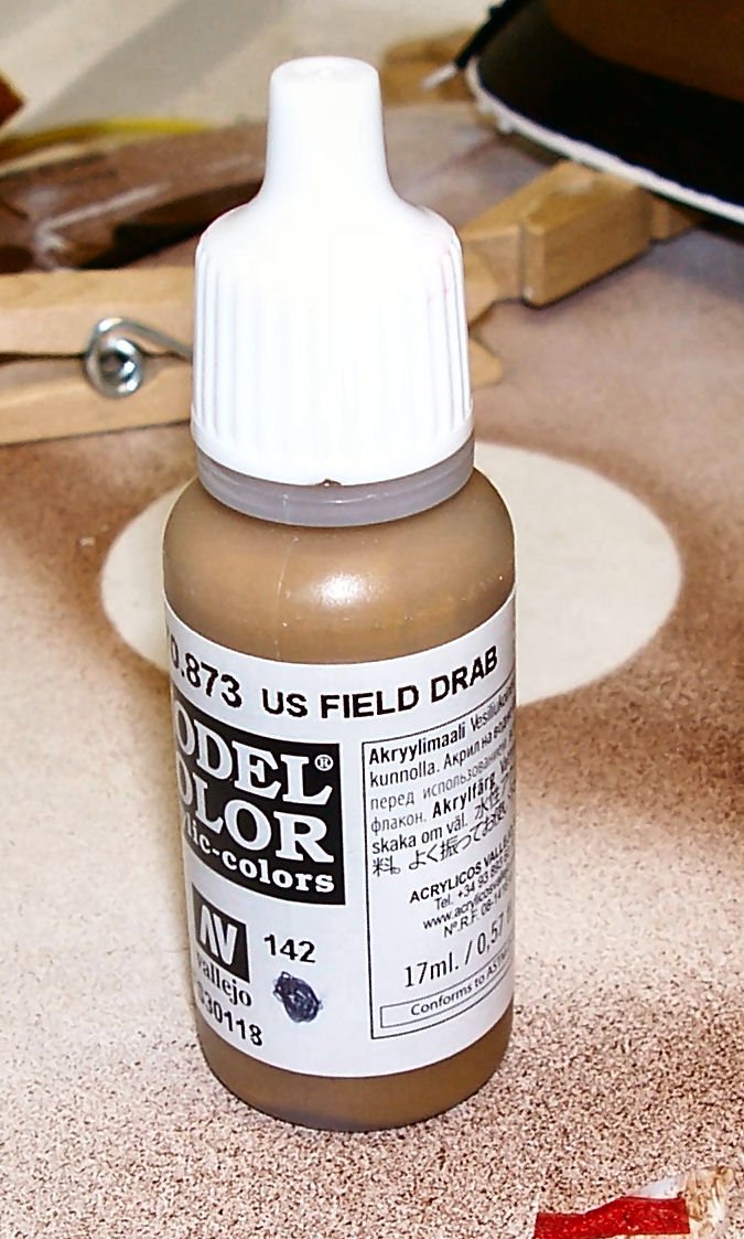
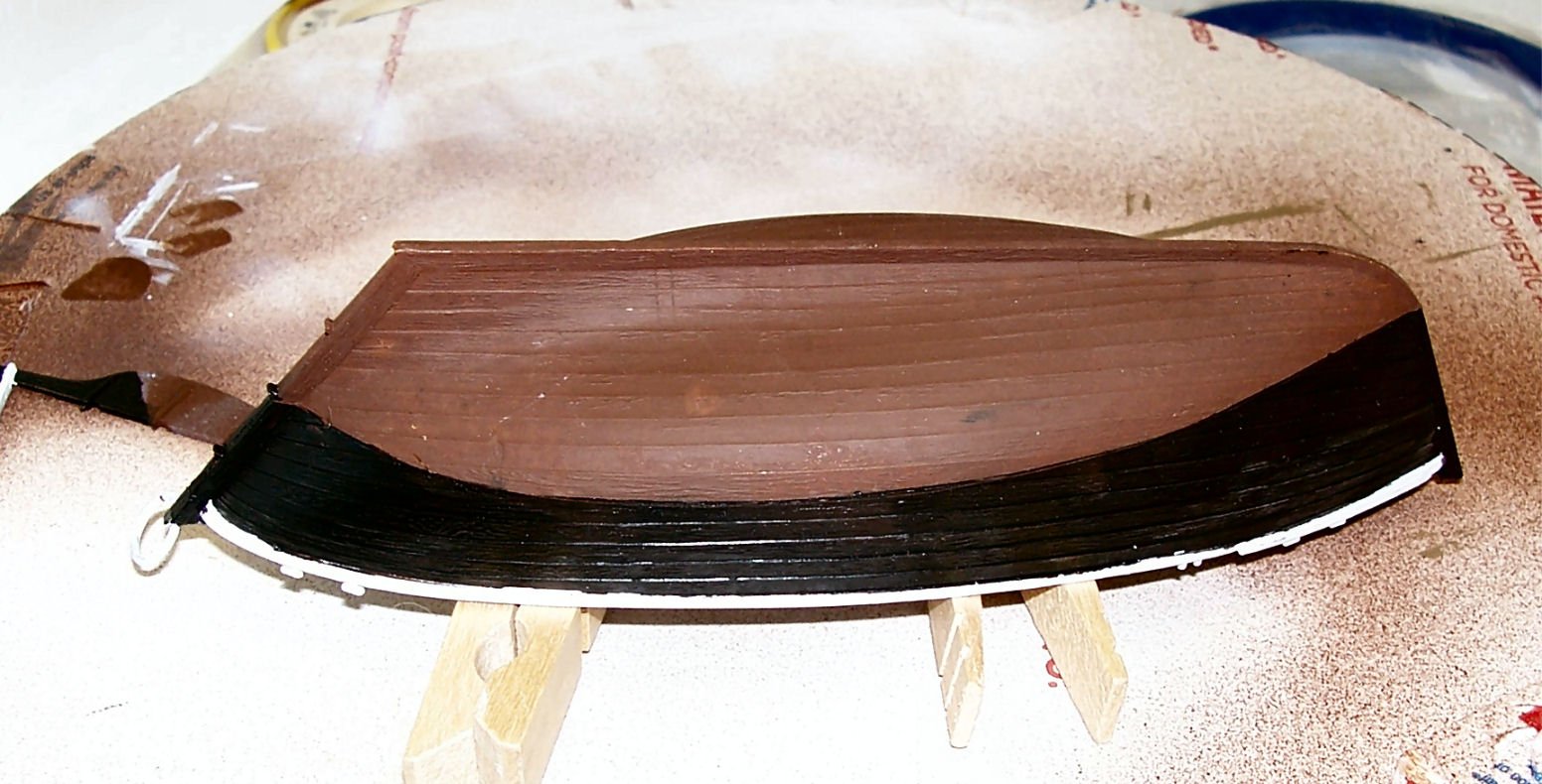
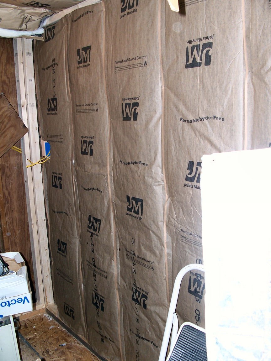
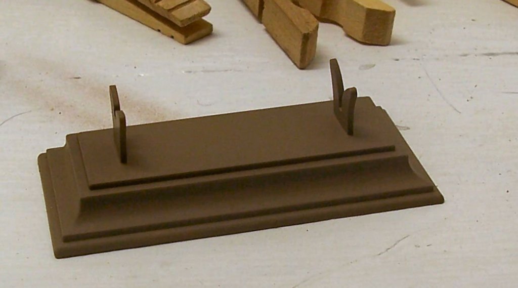
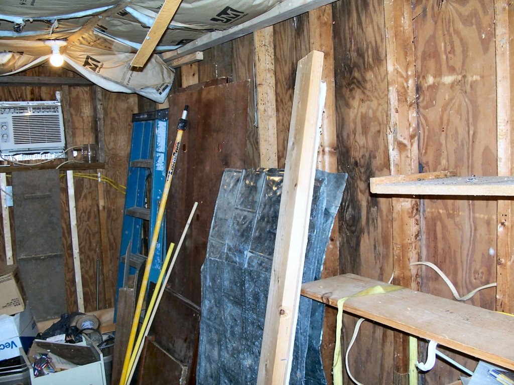
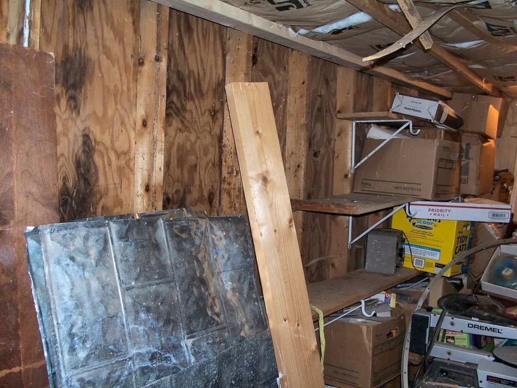
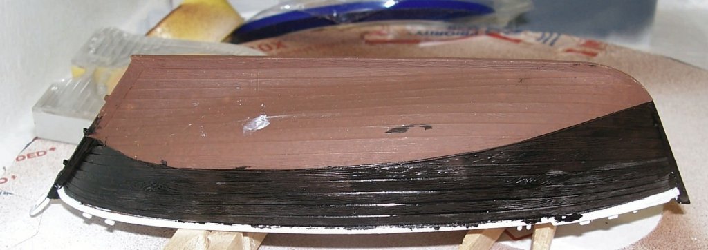
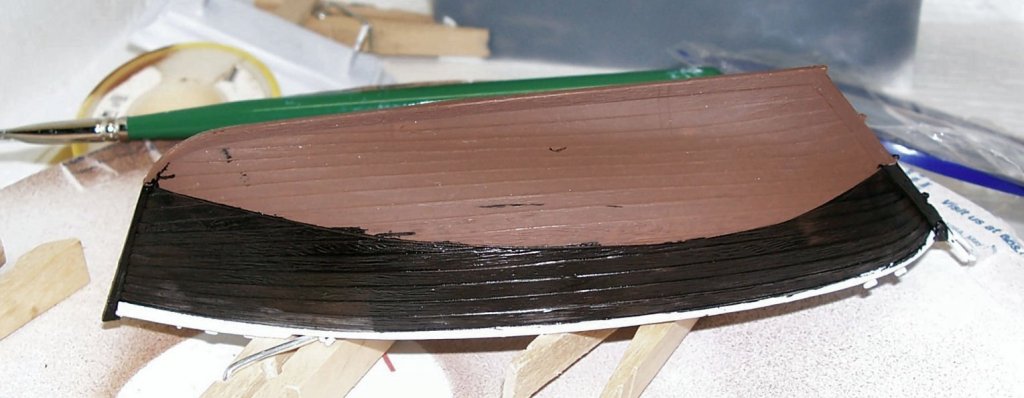
Sinagot Fishing Boat – Heller – 1/60 – Plastic - Small PART 9 Went back yesterday and did some touchup to the model with a brush, freehand. It looks better now, though there are still some spots to correct. As masking tape wasn’t developed when these boats were first built, a little roughness at the edges can be excused. “That’s my story, and I’m sticking to it!” LOL First thought I selected a color that I think looks right for a varnished spar/mast. Vallejo Model Color 70.873 “US Field Drab”….. was the closest I found in my stash of paints. It is darker then the Humbrol brown supplied with the kit. The pictures below show lighter streaks on the spars, this is the wet color of the paint, before it dries. This time I moved my magnifying light over to the spray booth, and painted using it. I found a world of difference when using it. Much better control. I’ll wait a week for the paint to set, before I mask off the metal parts, for their black paint. I also had to put 3 coats of the Model Color on the base to get full coverage. I’m thinking of using some of my Vallejo stains, really thin paint, to add some grain to the base. The stains come from the Vallejo “Wood and Leather” set. I’m also thinking of putting a gloss varnish finish on it, similar to a real wood base. For the name plate I’m going to do the “wood” area like the base and the Name Plate area in brass paint, both letters and background. Below are pictures of the touched up hull, still some work to do, but better. The last couple mornings I’ve been insulating the back wall of what will be the ship building section of the shop. This is the hardest part, as it is a 16x7 foot section of shelving. So I have to take down the “stuff” do the wall, then put the shelving and “stuff” back up. Limited room makes this interesting. I’ve gotten the left hand side double studded and double insulated (R-13 x 2 for R-26), so far. The side wall shown in the left of the first picture is already double studded, and has the through wall AC installed. The AC unit is a 5000 BTU window unit, semi-permanently mounted with bolts to the wall. A few years ago someone broke into my shop by pulling out the window AC unit, so now the shop has no windows and both units are bolted to the wall!


-
Thanks for this tip! I'd never heard of this before, and just looked it up. In the very near future, I'm going to build a model of Gutenburg's press and need to stain all the basswood pieces for it.
-
Which Glue: cooper wire on wood
thibaultron replied to MESSIS's topic in Metal Work, Soldering and Metal Fittings
I read an article years ago, about a model of a stationary steam engine at 1/32 scale, complete with every bolt of the original. Doesn't sound hard, until you find out that some of the bolts were 1/4 inch diameter 20 threads per inch, complete with scale hex heads and threads! The guy even made his own taps and dies to make the bolt threads and holes, as well as the wrenches to install them. The wrenches, at least were big enough to use by hand. -
Lighting the Work Area
thibaultron replied to Richmond's topic in Modeling tools and Workshop Equipment
One consideration is top match the light you are modeling with, with the light you will be displaying your models with. While not as big a consideration with wood ships, if you paint your models, the colors may be off if the two types of light are different. This is an important point for model railroaders. -
In my Model Railroad Club, we have a saying, "We always get it right, the fourth or fifth time!"
-
Merry Christmas to you too Frank! Glad to hear the treatments are done. I hope you can get back to building again soon! Best wishes!
-
Vasa deck shift
thibaultron replied to BLACK VIKING's topic in Building, Framing, Planking and plating a ships hull and deck
I read the Red Bay books on the Basque whaling ships of the 1500s. Same thing. Different materials used from frame to frame, random hull planking, including one short plank that only went between adjacent frames. The tree nails in the hull were drilled with the left one at the top and the second below and to the right of it in some sections, and the opposite in others, etc. -
Welcome aboard!
-
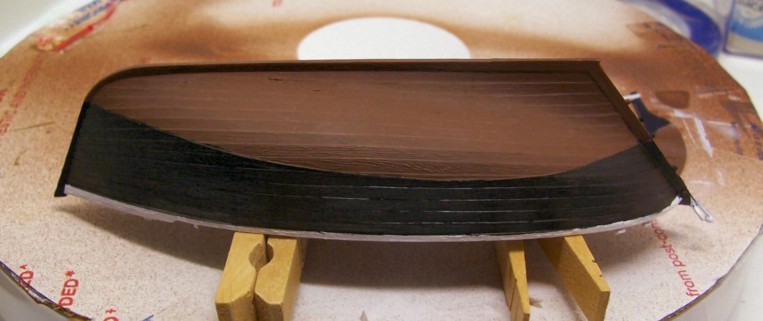
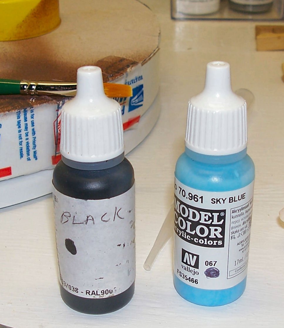
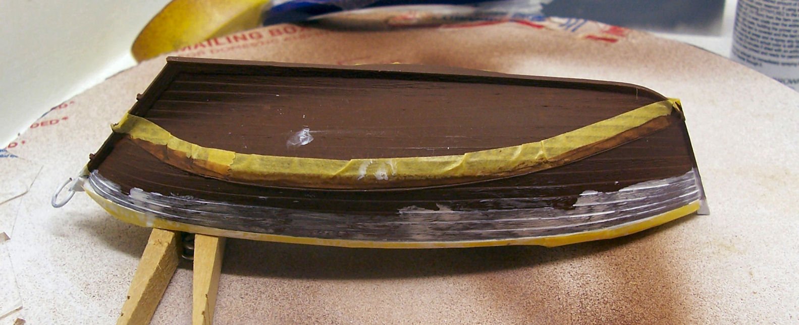
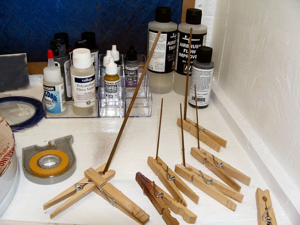
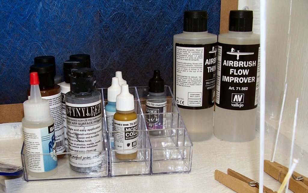
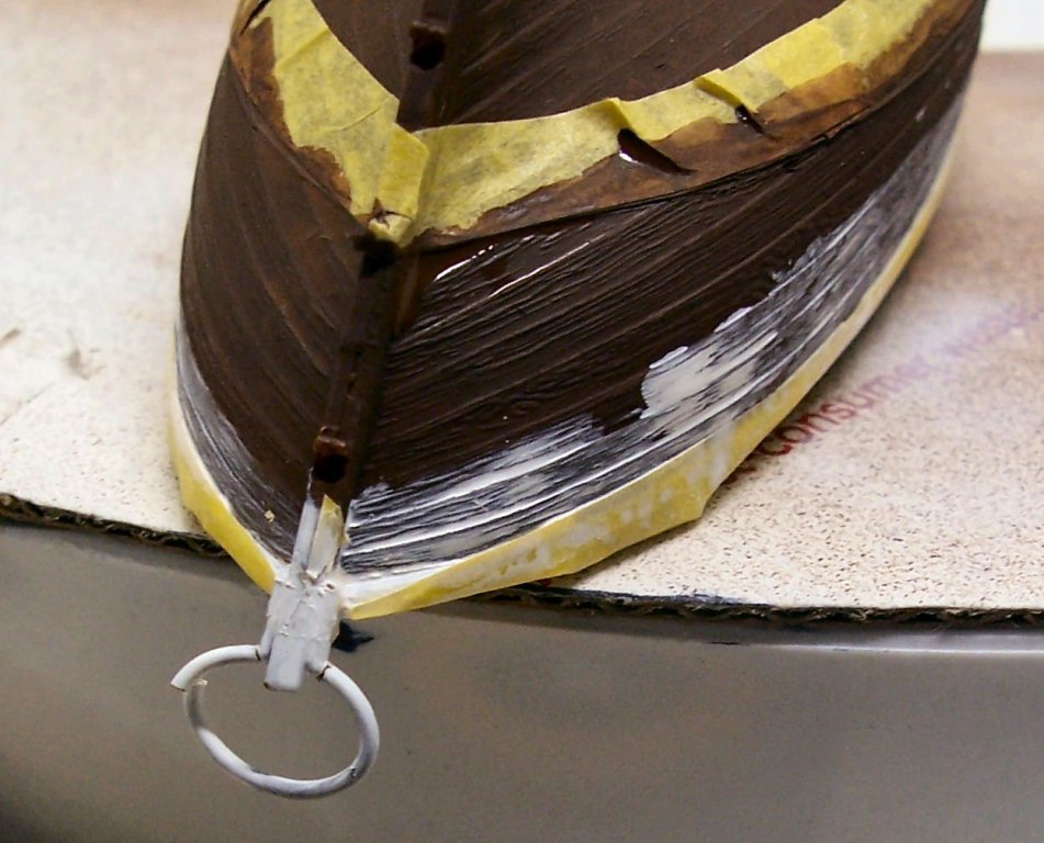
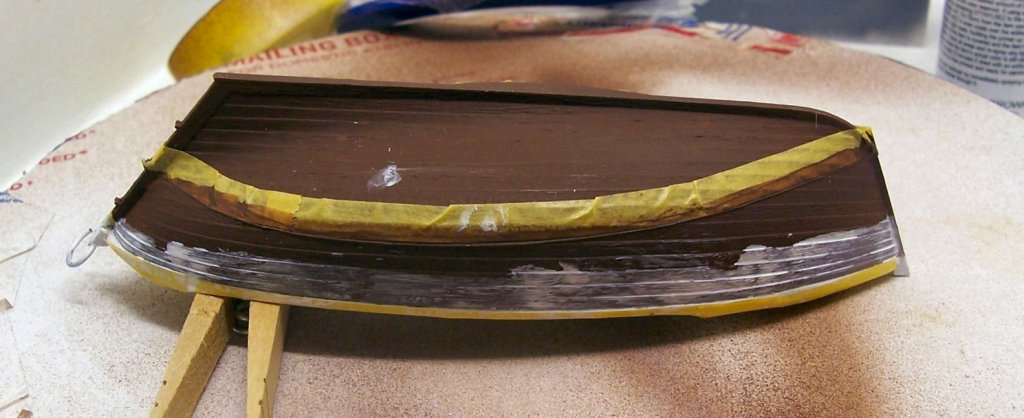
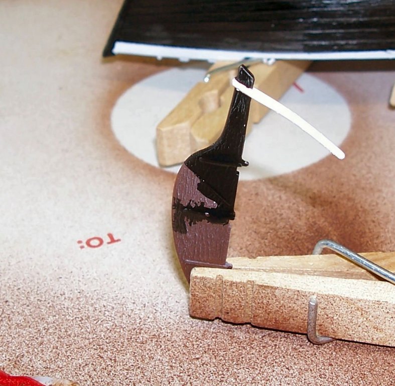
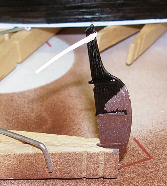
Sinagot Fishing Boat – Heller – 1/60 – Plastic - Small PART 8 Finally got a chance, last week, to get back to painting. Major fail! Seems I need a lot more practice with masking and brush painting. One thing I definitely need is to either get a second magnifying light for the spray booth, or bring my workbench one over when I’m painting. My eyes are definitely getting older! Anyway, to start with I found a neat item I’m using as a paint bottle holding tray at Dollar Tree. I think it was in the cosmetic section. It has one large section that is great for the larger primer bottles, and 8 smaller sections, just right for holding a bottle of Vallejo paint. For the upper hull I’m using Vallejo Model Color Black and I’ll be using Model Color Sky Blue for the interior. The blue is not quite a direct match for the Humbrol blue supplied with the kit, but it is close. I noticed that while masking the hull I damaged the thin plastic traveler. I will try to repair it later. I may have to fashion a wire replacement, as there is still quite a lot of handling to be done in the future. So I masked off the bottom of the hull and the railing, then I painted on diluted white and hull red at the tape joints to try and seal them, but either I did not burnish the tape down enough, or I lifted the tape with the brush. Burnishing over the cast in wood grain is difficult to start with, so that may also be contributing factor. Here is what I found after removing the tape. I also managed to get some of the paint on my gloves, and onto other areas of the model.

-
I use the scan, then trace method using DesignCAD and the Curve function (a type of Spline curve). After that I use the 3D feature of my CAD to place the frames in position, and draw in the horizontal water lines connecting the frames. By viewing them from the top, I can see any deviations from a smooth flow of the lines. I then redraw the curves skipping the frame with the "bad spot". Then I bump that part of the frame in/out to meet the new line. I then redraw, and check that the lines are now smooth. Generally a couple of iterations will give me good frames. This works well where you are just given the frames drawn, but no body plan. I was able to generate all the aft frames of an old kit, where the frames did not even come close to making a hull, as drawn. If the drawing was acurate. I think the manufacturer deliberately distorted aft frame drawings, so that you had to buy the kit, to build the model.