thibaultron
-
Posts
2,952 -
Joined
-
Last visited
Content Type
Profiles
Forums
Gallery
Events
Everything posted by thibaultron
-
The Model Ship Builder forum has a thread on a scratch built version. You may get some info from it.
-
 My panting skills where further aided by my cat! It was very cold, for here, yesterday and she slipped into the shop. Normally she goes off and hides, so I can't put her back out. Yesterday, however, once I got started painting she came over and sat on my lap, and kept bumping my arm, for attention! I didn't want to put her back out in the cold, and if I took her back to the house, I would have had to clean up all the paint "stuff" first. At least there are no cat hairs in the finish!
 -
Got a bit more painting done. I'll post pictures later. Still need to improve my skills in this area.
-
Thanks. I was hoping there was some trick I couldn't think of.
-
CA adhesive, which one do you use?
thibaultron replied to Modeler12's topic in Masting, rigging and sails
Also take into consideration availability. Look for a local source. The best CA on the market, will be of little use, if you run out in the middle of a session, and have to wait while you mail order more, or until you can drive a long distance to get more. While you should keep track and order more in time, some times you forget, or the glue, for whatever reason, sets up on you between modeling sessions. -
Chuck, a question about the mast step. Could you have positioned the mast without gluing the little square mast step, temporarily attached it, then used it as a guide to drill the hole in the floor boards? If so, how would you go about temporarily attaching it? Just a question, not a criticism.
-
Did some more painting today. This time I was using a brush. I repainted the spars, as the airbrush did a poor job on them. I also hit the interior areas of the hull that the airbrush could not reach. I did have to add a little water to the Stynylrez to get it to flow well with the brush. Tomorrow, I'll paint the ends of the spars now being held by clothespins. I've also been slowly translating the Sinagot book from French. I hit a snag though. While on vacation, I was using my laptop, and it picked up a virus. I had to do a full scan of it and the external drive. It took 35 hours. Now I'm rescanning it to verify that I got it. Once that is done, I'll transfer the files to my desktop, and continue.
-
In DesignCAD you can also goto "File/Image/Save Image File" to save a graphic of the screen/drawing. I don't know if TurboCAD has a similar command.
-
Looks like they fall on the frames too. In any case you can always plank with full length stock, and scribe in the butt joints as each plank is in place, but before the next is laid. If using butt blocks, they can be glued in opposite the scribed joint. Saves trying to do it with shorter lengths.
-
In reading about the history of the British navy, there was one Admiral who was, both extreemly egotisical and sadistic, his favorite tactic was to call captain to his ship, while keeping it under full sail. It could take hours for the Captian's longboat to reach his ship! Perhaps the contemperary model with the extra thole pins were a response to adding extra rowers for this situation. By the way he is also the person who, when he became a Lord, fired all the elderly workers at the Navy dockyards, putting them pennyless onto the streets, as a cost saving measure. In the past the workers had been given small or light tasks, when they became to fraile with age or illness, after they had worked the heavy labor at the yards for years.
- 421 replies
-
- 3
-

-
- medway longboat
- Syren Ship Model Company
- (and 1 more)
-
Tung Oil "Experiment"
thibaultron replied to knightyo's topic in Painting, finishing and weathering products and techniques
Thanks for the reminder! -
I wish I remembered all those years of French I took, 45 years ago!
-
I have the Red Bay books, and can also recommend them!
-
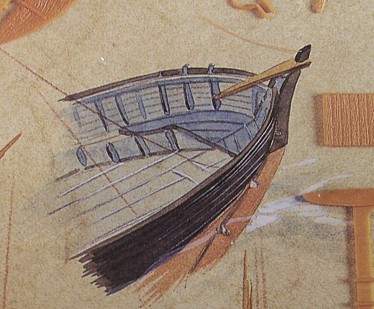
Got my Sinagot book today! While I can't read French, it does have many diagrams and boat sketches that show the rigging. I may scan the book and run it through OCR and French to English translation programs.
-
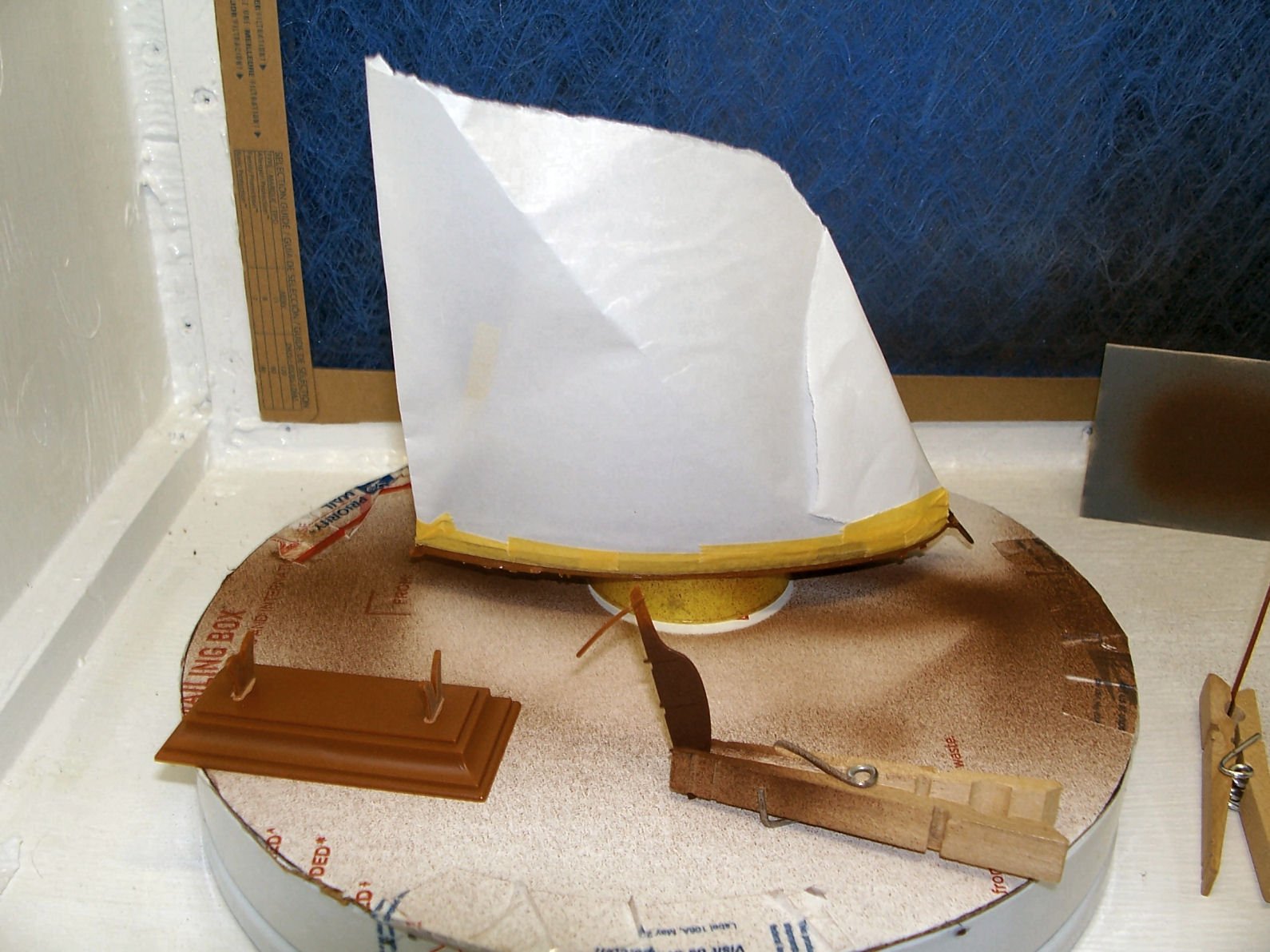
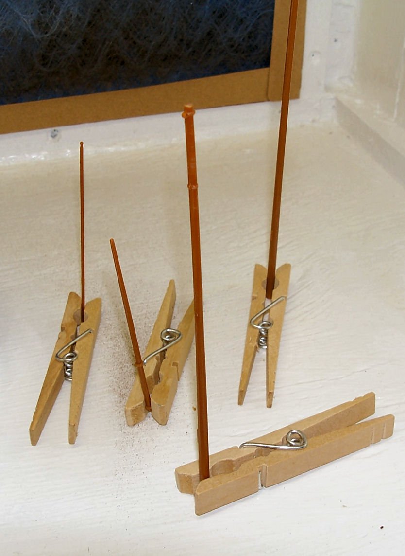
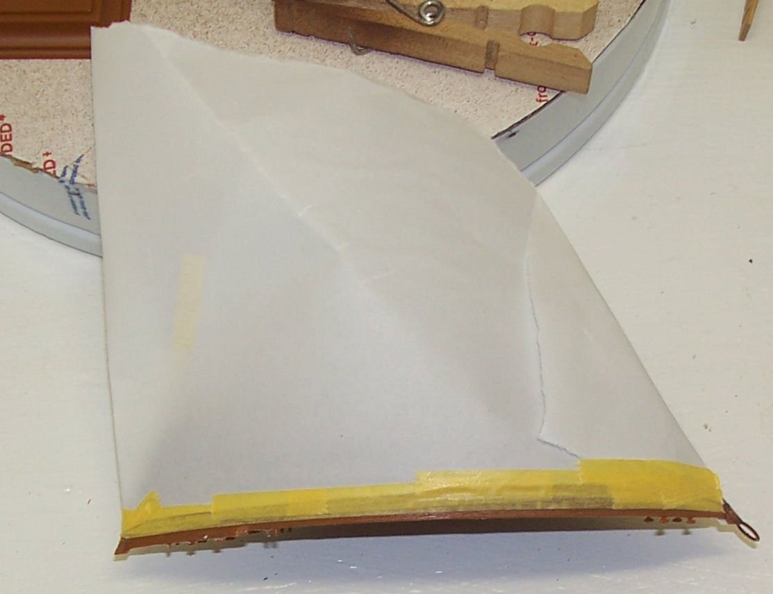
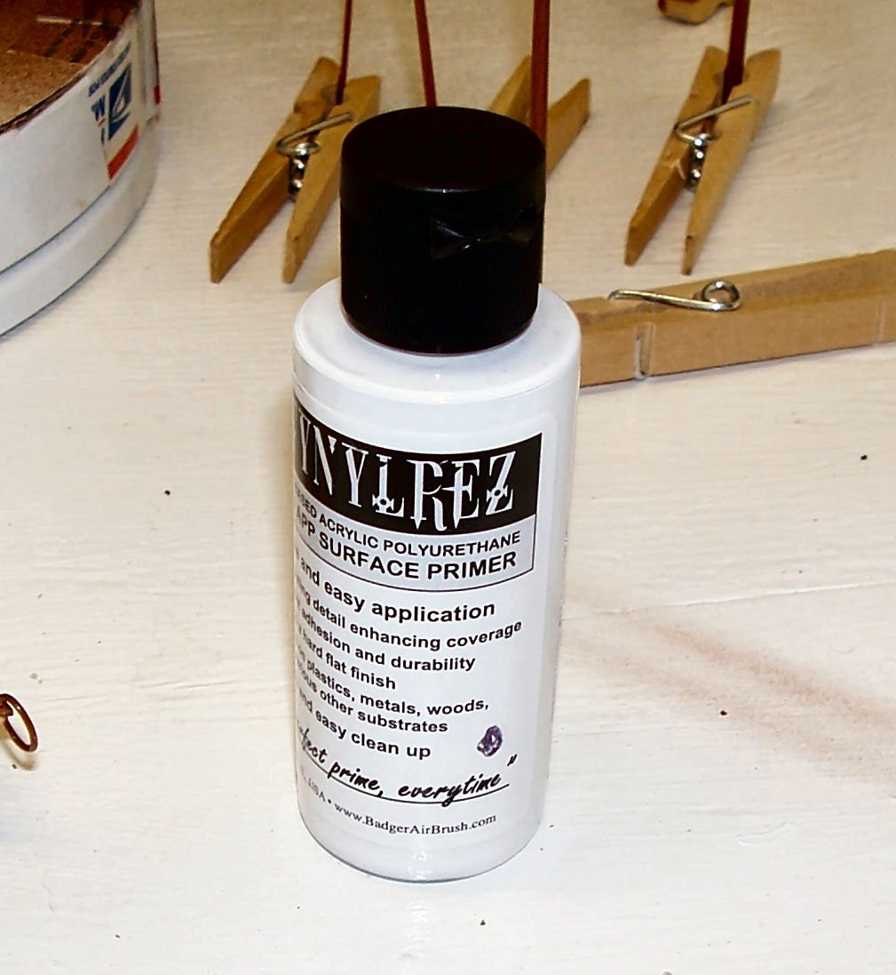
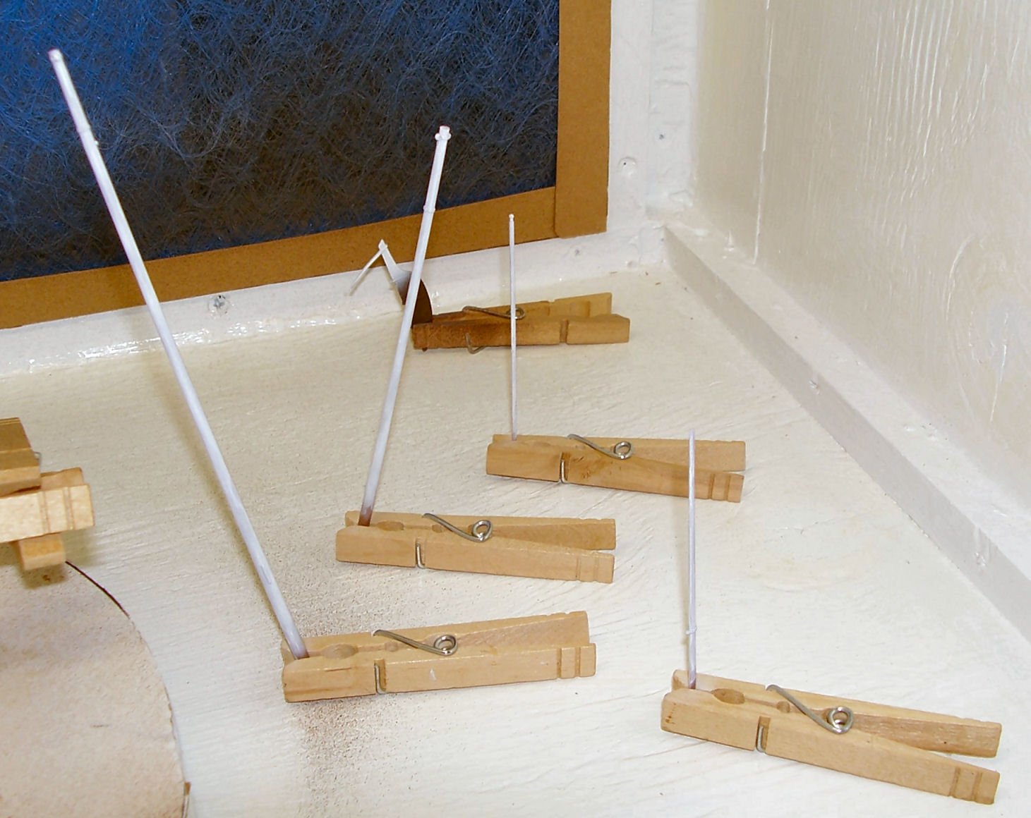
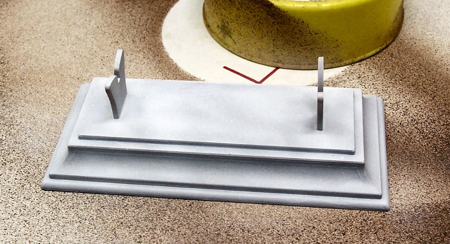
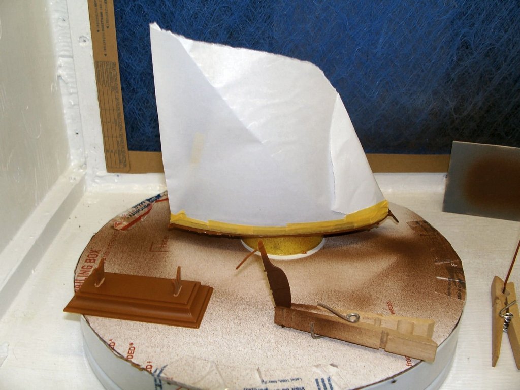
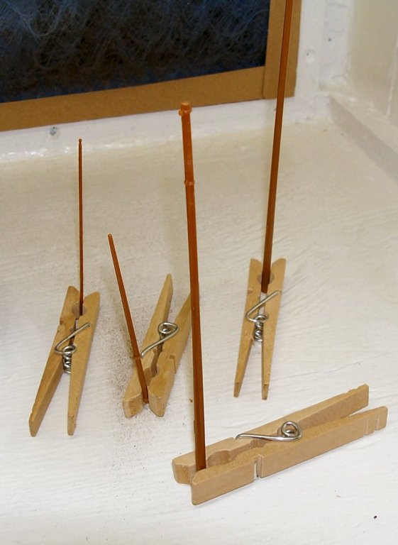
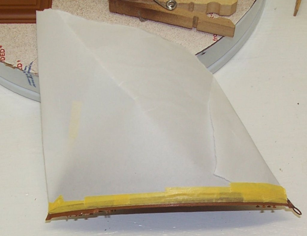
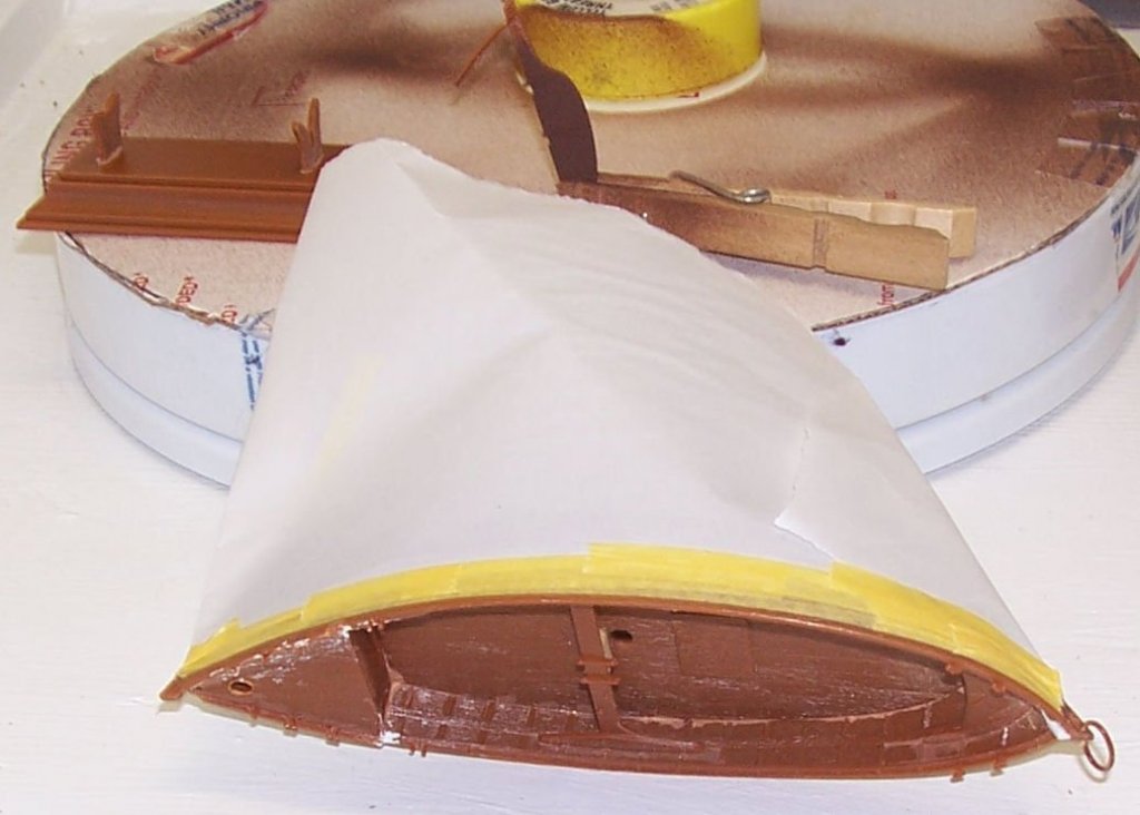
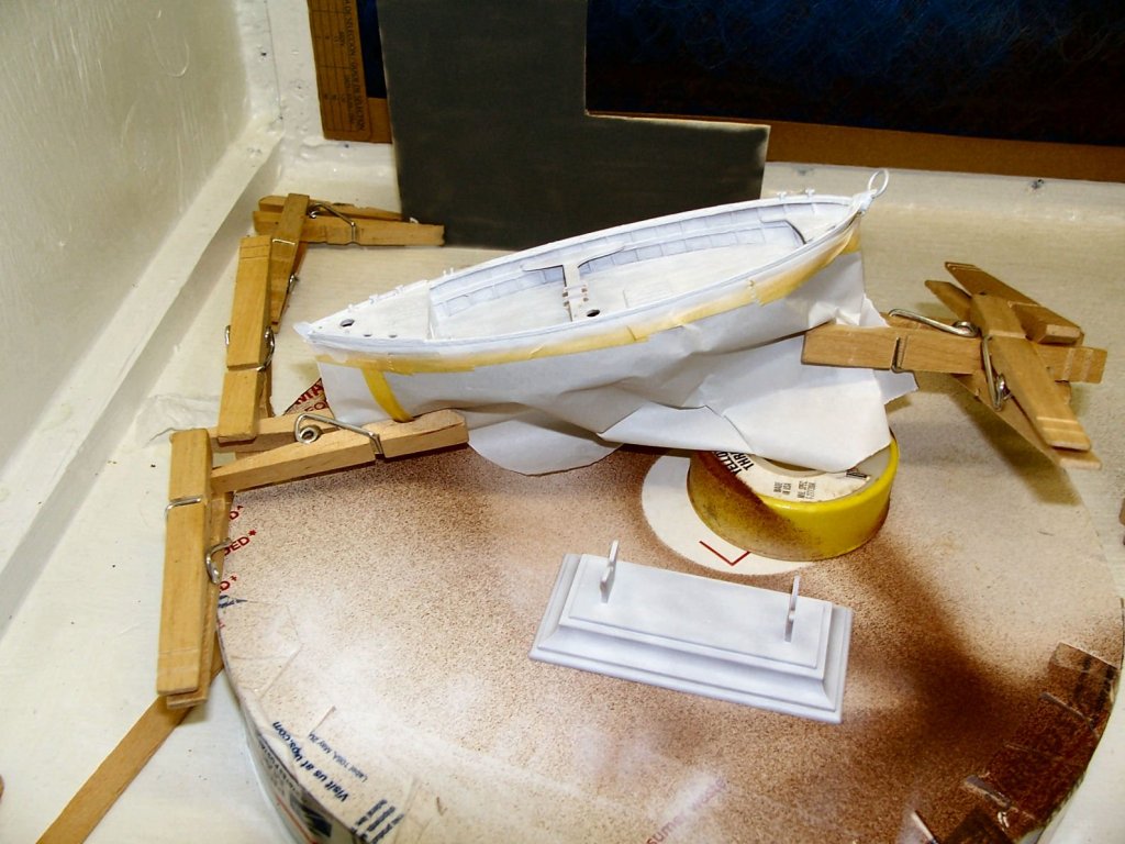
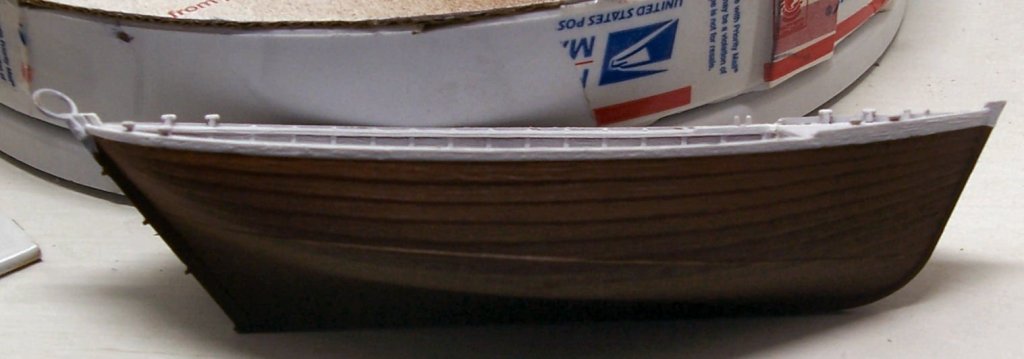
Sinagot Fishing Boat – Heller – 1/60 – Plastic - Small PART 7 Today I shot the next coat of primer onto the hull and several other pieces. First Note: Applying masking tape with gloves on is a pain in the a..! It was bad enough when I was using the old style enamel paints, now that you have to wash the model and then handle it with gloves on until painting is finished is not fun. With the acrylic paint, you have to have an oil free surface for proper paint finish, that includes skin oils! Second Note: Trying to airbrush long thin plastic pieces with an airbrush causes interesting oscillations at the unsupported end of the part! Next time I’ll brush paint these parts! This was aggravated by the need to use about 30PSI to the airbrush. More on that later. Third Note: Using a double acting airbrush for anything other than small parts is frustrating, and takes forever. Fourth Note: When using said airbrush with Stynylrez, and I guess most acrylics, for an extended period, clean out the airbrush regularly, even if you don’t change colors! I was painting for about an hour, and almost needed a chisel, or sand blaster to clean the paint out. It had dried inside the passageways and the inside surface of the cup. Fifth Note: Also completely disassemble the brush and check the needle, etc. when cleaning after using the Stynylrez! When I used the double acting brush when I was practicing, I cleaned it out and ran cleaner and water through it. When I went to use it this time, I had filled the cup, and then tried to use the trigger, it was stuck solid!! I disassembled the brush and found a crust of the Stynylrez all over the needle! After this session I broke it down all the way and cleaned it. When I was using the Vallejo primers and paint on another model, the brush cleanup well without the disassembly. I chose the double acting brush for this job as there were a number of nooks and crannies under the seats. I felt that the external mix brush delivers too much paint and would flood the interior while I was trying to get under the seats (Yes, I know that there is a perfectly Nautical term for them, but everyone knows what a seat is), especially under the one at the stern. In the end I will still have to go back and brush some under both seats. I shot it at 30PSI, the upper limit in the Stynylrez directions, using a 0.50 needle, also as per directions.. As noted earlier, this high pressure caused a couple of the smaller spars the oscillate when I was attempting to paint the far end. Also trying the use an airbrush to paint long thin round “things” is difficult. From now on I’ll brush paint both the primer and topcoats. I plan to brush paint the interior for the color coat, but wanted a smooth primer coat to start from. In the pictures below are the taped hull and the rudder and spars held in clothespins. When I primed the rudder with the Red-Brown primer it was held by the tiller end, so I had to hold it by the bottom today and prime that end. I used Tamiya masking tape and some fairly heavy white paper for the masking. I was going to use regular masking tape for the Tamiya to paper joint, but decided that it was both too wide and I was afraid too sticky, and might pull off some of the primer. I masked the hull below the railing, as the hull will later be painted black. I chose to do the rail first, as the Stynylrez sets much faster than the Vallejo color coats, so I can mask it several days sooner than if I had to mask the black color coat. The next two pictures are close-ups of the masking on the hull. As I said earlier it took a long time with the double acting brush, but I got the job done. For priming the other ends of the spars, though, I’ll use a paint brush. I also need to go back through the box, there is one of the yards missing, from the washed parts! I had other things to do today, though, so I didn’t get to look today. Sixth Note: I will buy some of the poster board sheets, and cut some to cover the bottom of the inside of the booth, even with the little painting I’ve been doing, it is starting to become “Not White”. This is the bottle of primer, I put the black dot on the label (lower right) to indicate that it is open and that I’ve put a stainless steel BB in it to help mix the paint, before use. I bought two sizes of specially coated balls, 6mm and 8mm (I believe), for this purpose. I read that regular SS comes in many types, and most of them will rust when constantly immersed in water based paints. I’ll look up the manufacturer and post the name later. I use the 6mm for the regular Vallejo size color coat bottles (17ml), and the 8mm for the larger primer ones (2oz in this case). I tried glass beads, but even large ones are too light. From my experience today I think I will thin the Stynylrez a little, next time, and add a couple of drops of retarder to help with the fast drying inside the airbrush. I also need to dip the needle in a lubricant, to help keep the paint from adhering to it. I have a bottle of the Badger brand, but forgot about it today. It is “Regdab” (Yes, that’s Badger spelled backwards, who can tell with Marketing Types!). No picture of it, it is buried under junk, due to the (eternal) remodeling of the shop. The next two pictures are of the result of my efforts, before I removed the masking. Note the “Rube Goldberg” clothespin setup to support the hull until it dried. The gray piece behind the model is my Test Piece. I use it to see if the airbrush is working, paint consistency, etc. You’d almost think I knew what I was doing, nope, just figuring it out as I go. It does not show in the picture, but the coat on the spars leaves much to be desired. And pictures after the masking was removed. The pictures have different contrast levels as some are taken with flash and the others without. I choose the pictures that show the best detail, rather than worrying about how they look compared to each other. As can be seen by the two side shots, I need more practice with the masking, but it is OK. The model also has the standard out of scale raised grain patterns, typical of plastic models, working against me here. When I paint the black for the hull, I’ll use an old trick to help with the bleeding. After masking hit the edge with a thin spray of the color you are masking off, in this case white as I’ll be protecting the railing, or with a clear coat. This way any paint that bleeds through matches the protected color and seals those spots for when the new color is applied. As also can be seen in the third picture the primer coat is a little spotty, due to trying to cover a relatively large area with a small spot size of paint. It will do for the primer coat though. Again I’ll brush paint the light blue interior color coat. For the railing I went over the area many times to build up the opacity. If I had to do a larger area, than the railing, the double acting brush would not be a good choice, or I'd apply a white color coat. The last picture is the primer coat on the stand. Again not an opaque coverage, but the color coat will fix that. Another problem with using the airbrush on this small part was that it was being blown all over the booth whenever my grip slipped.


-
Thanks everyone!
-
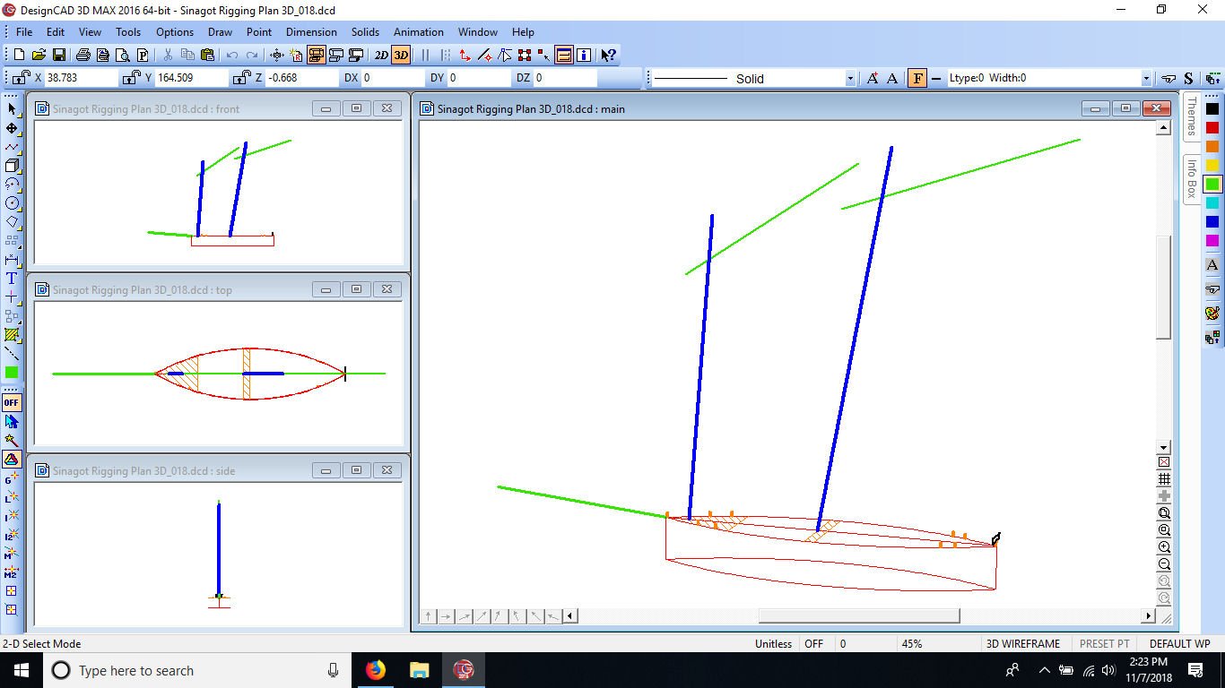
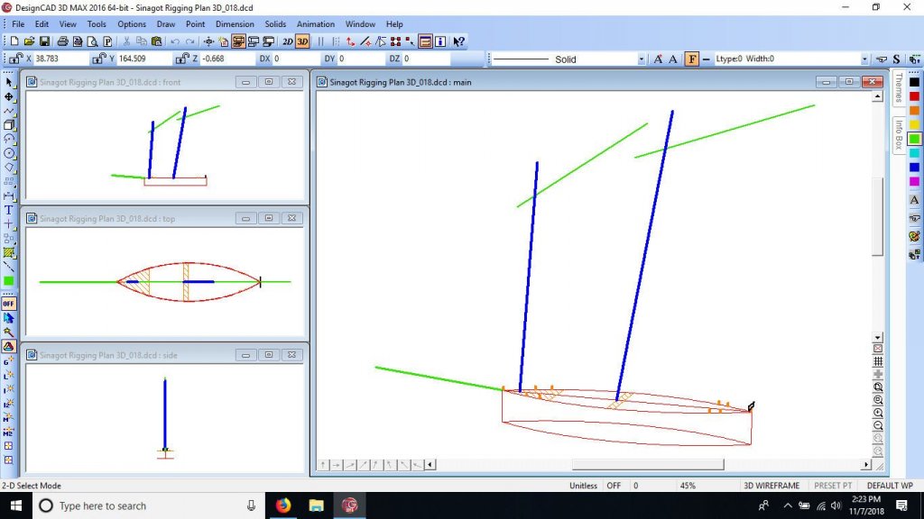
It doesn't look like much now, but here is the rough 3D CAD "Clothes Horse" I drew to start my rigging plan. I'm going to draw in the lines as I find them using the photos I found. The red is a very rough representation of the hull, the green the spars, and blue masts. The orange points are the bitts on the hull, and the black the traveler.
-
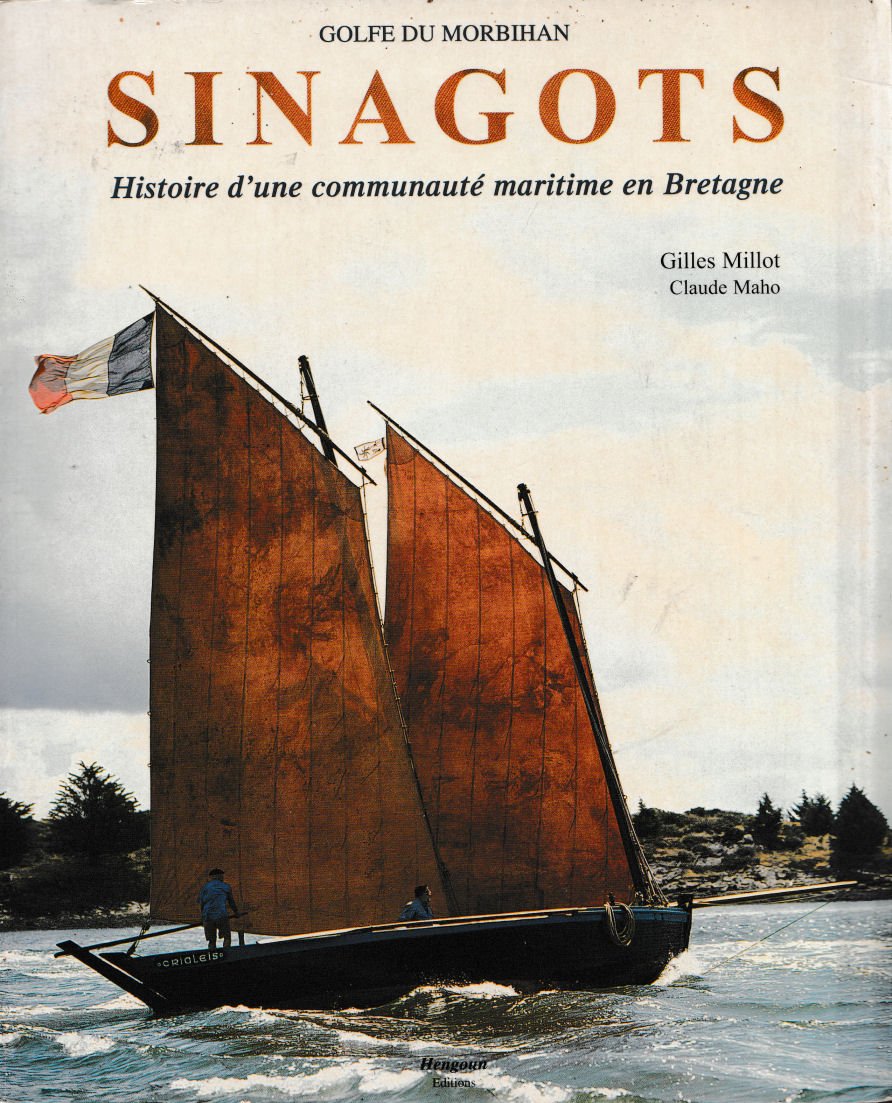
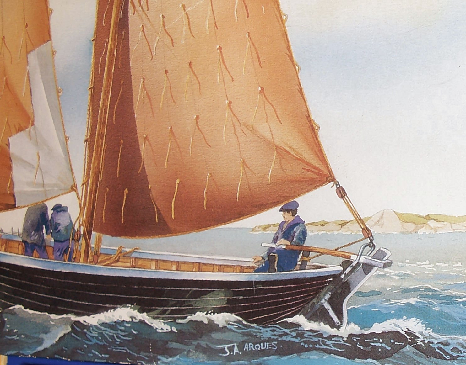
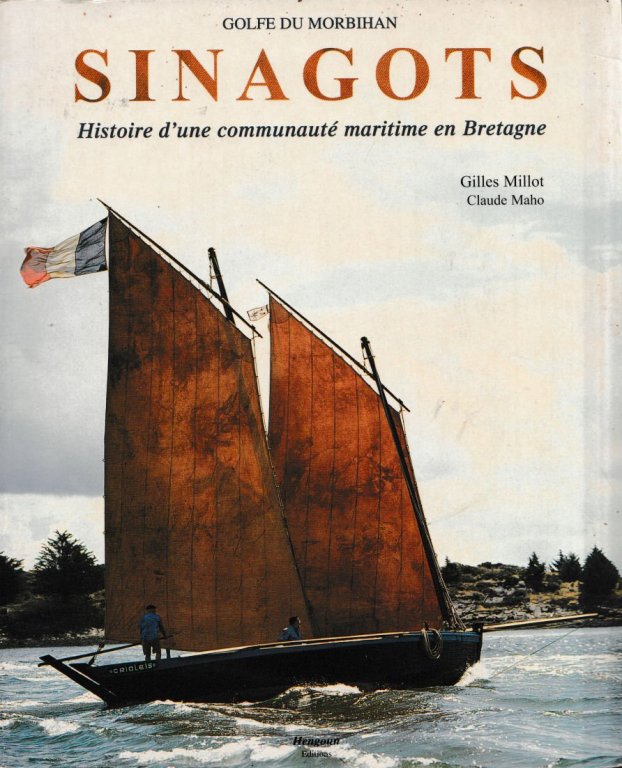
No progress on the model itself, but I did find several pictures of restored Sinagots online. The most useful search was for "Jolie Vent" a restored boat originally built in 1958. Several pictures that will help me figure out the rigging. I also ordered " Sinagots : Histoire d'une communauté maritime en Bretagne " a book on the Sinagots. Its in French, so hopefully it will have lots of pictures! I may have to scan it in and use google to translate it! I did find out that the boats were used in protected waters, and had no dedicated stays or shrouds. The sails are set so that the foresail is always raised on the Port side, and the main on the Starboard. When running into the wind, one of the sails billows against its mast. The boats generally had black hulls and were differentiated by the color of the railing. There is a wooden kit in 1/20th scale, but I can only find it from one supplier, and will stick with the Heller one. There is a nice video of "Jolie Vent" at
-
The polyester also uses the heat of the reaction to set, and in thin sections may not harden well. One one of my Combat Warship models, I had to put the hull in the hatch of my car and park it at work so that the sun shone in all day. It took several days to finally set fully. The car stunk to high heaven for a week, but my hull was ready.
-
Great workmanship. I hope mine comes out half as nice.
-
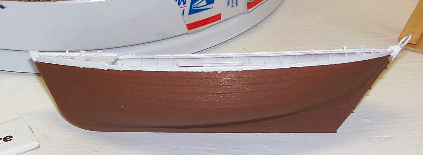
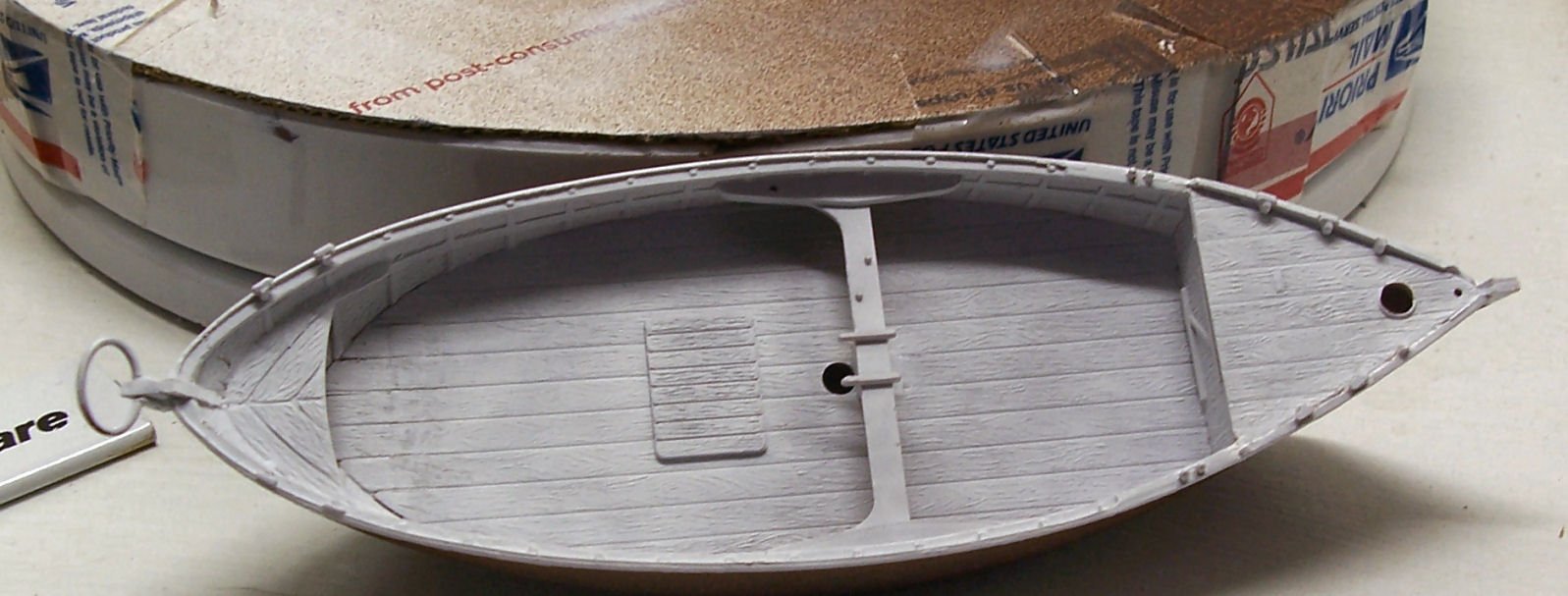
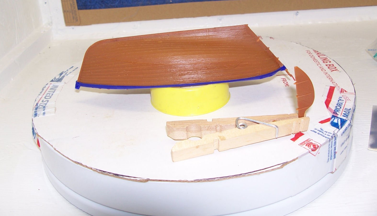
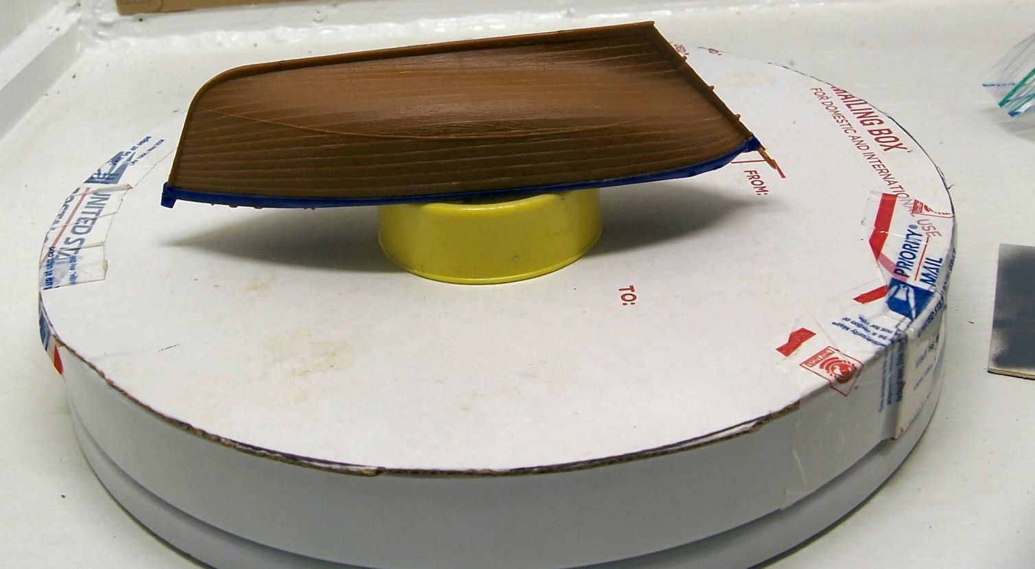
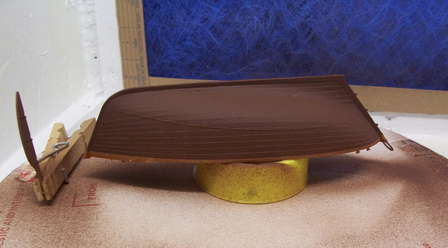
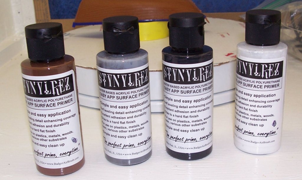
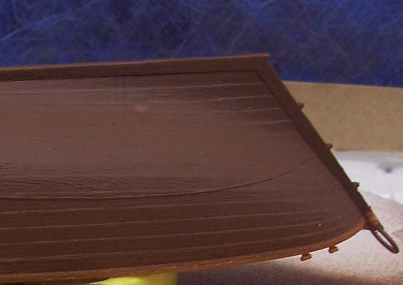
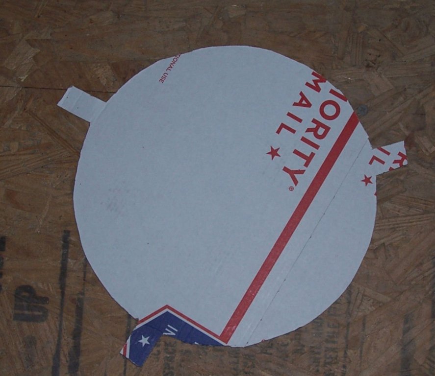
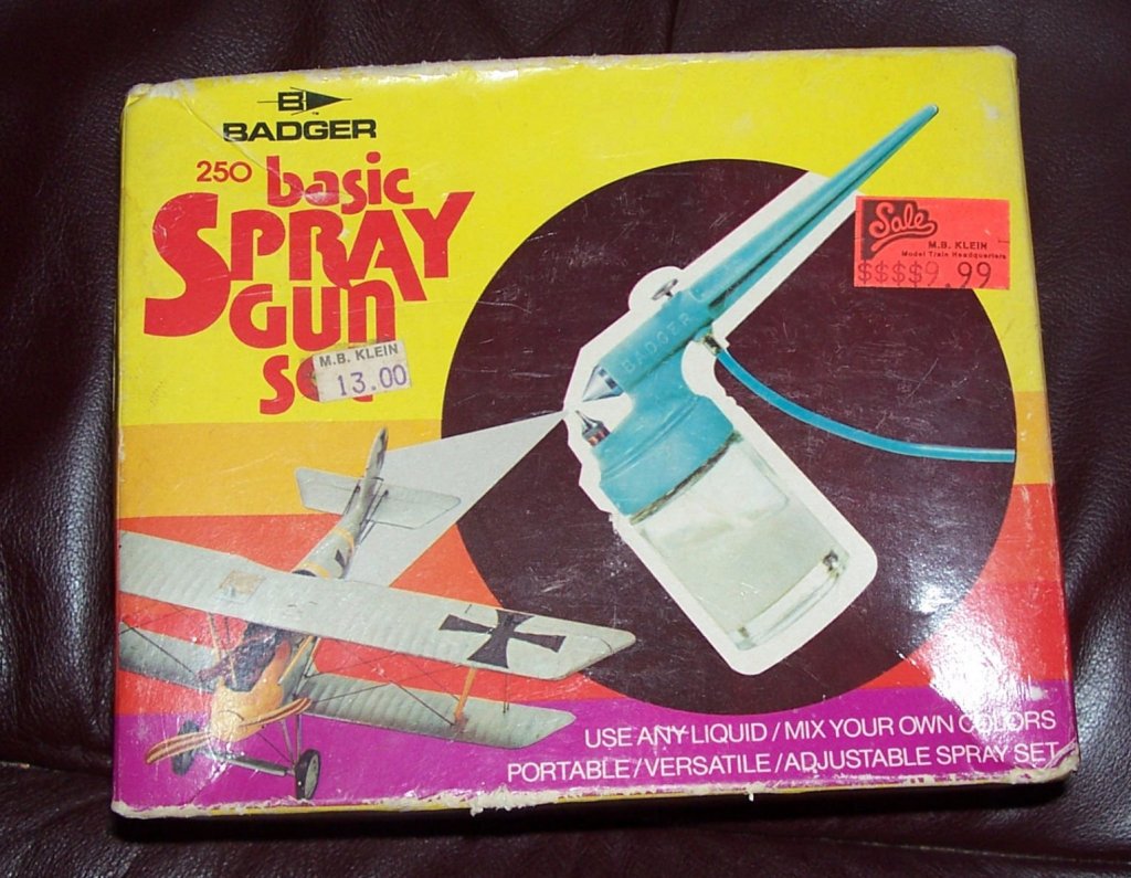
Sinagot Fishing Boat – Heller – 1/60 – Plastic - Small PART 6 After much delay I am one again working on the Sinagot! I bought some new Stynylrez Primer. I had gray, but wanted to get at least their new (since the last time I bought the gray a couple of years ago) Red Brown, to use as the anti-fouling bottom paint. While looking at Amazon, I found a three pack of Gray, White, and Black, also, so bought that to. I'll used the white for the railing (painted white in the box art), and the interior, which is a light blue, then the gray for the rest of the parts. Here is a shot, from Part 4, of the box art, on the front of the box, showing the white railing. This picture varies from the next and the instructions, in that the hull interior is shown as natural/tan. The next picture, also from Part 4, is from the back of the box. It shows the light blue interior, as per the instructions, but with the railing in black. I chose the white railing for my model. I'm also going to go with the Main Sail Traveler in black, like almost all iron work on ships, and the rudder pindles and grunions the same color as the surrounding area (black above, anti-fouling below). I had already washed the parts down to remove molding and skin oils. This is a very important step with the new acrylic paints. After that you need to always wear plastic, latex, etc. gloves while handling the parts, until painting is completed. I stored the washed parts in a clean covered cardboard box, until I was ready to paint. After painting I left them in the spray booth to dry. The booth has a removable front cover to keep the dust out. I just painted the outside of the hull and the rudder, with the Red Brown primer. I taped off the railing area, for its later coat of white primer. Below is a picture of the hull and rudder sitting on the painting turntable. The turntable is one I modified from a two tier plastic one I found at a yard sale. I cut off the tube connecting the upper and lower tiers, and made some rough round cardboard covers for the lower tier. I just traced the outside of the tier onto a collapsed mailing box, which was made with thin cardboard, and added three tabs that fold down over the sides, so that I can tape a cover in place. I cut through both layers of the box, giving me two covers when finished. Of course, as it is illegal to use the USPS boxes for other than mailing “stuff”, I always save and use only the ones from packages that I receive in the mail, right. I used the turntable for the hull, and held the rudder using the clothespin when painting. I used my 35 or so year old Badger 250-1 airbrush for the primer coat. The double action brushes produce too fine a line for easy coverage of large areas, which even this small hull constitutes. While external action brushes like this brush (and this one is a very kludgy cheap introductory design) generally give a rough surfaced coat of paint, compared to even a spray can, the Stynylrez smooths out nicely as it dries. I will say though that this is the first airbrush I bought, and the one that showed me I could use one, and get a better finish with the old enamel paints, than with brushes. It also showed me that the airbrushes could be cleaned without the Herculean effort always talked about in the magazines of the time. You may ask, “What is wrong with just taking more time and using the double action brush, or a quality external mix brush?” The answer is over spray and the temptation to pull the airbrush back to get a wider line. Especially the later, as pulling back from the surface gives the paint more time to dry, before it reaches the model, and can leave a rough powdery surface. I learned this from a YouTube review, that unfortunately the address for is on the hard drive of my dead desktop. When I finally get a new computer, and can get to the content on those hard drives, I'll post the address here. Here is the painted shot and then one after I removed the tape. On a side note, I found as couple of spots on the hull after I finished cleaning the airbrush! I'd accidentally sprayed a few drops of either water, or cleaner on the hull! I resprayed those areas with the double action brush, and will, from now on, move to another area to clean the equipment! After a couple days to allow the paint to fully dry, I'll mask off and paint the rail and interior, in the white primer, as well as paint the top of the rudder, that was shaded by the clothespin.


-
Also each Captain setup the rigging on his ship as suited his "ideal" setup, so each ship had some variation, even from captain to captain.