robnbill
-
Posts
841 -
Joined
-
Last visited
Content Type
Profiles
Forums
Gallery
Events
Everything posted by robnbill
-

soldering torch vs iron
robnbill replied to rtropp's topic in Metal Work, Soldering and Metal Fittings
Since I generally have very small soldering jobs, the micro torch has been my go to tool for this. It has a refillable propane tank in it's handle. -
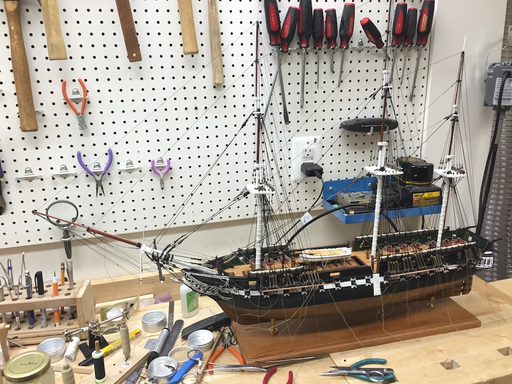
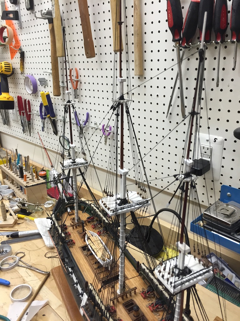
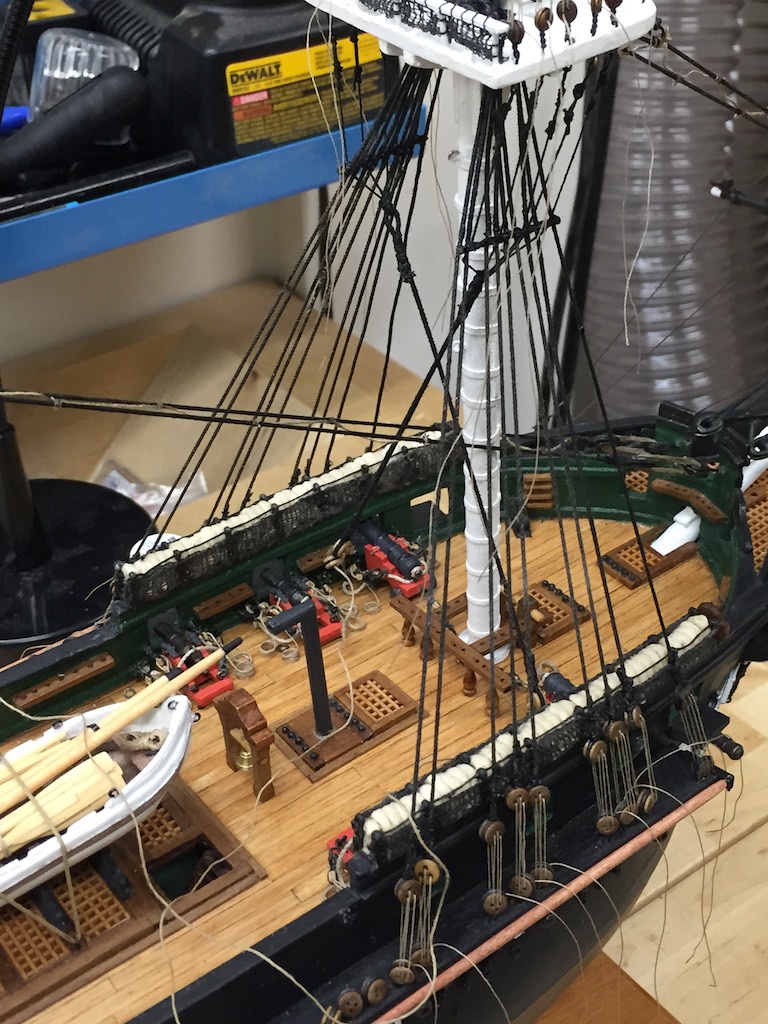
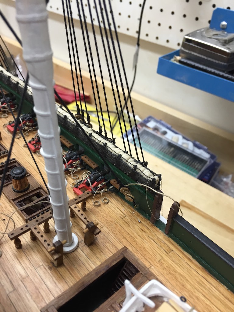
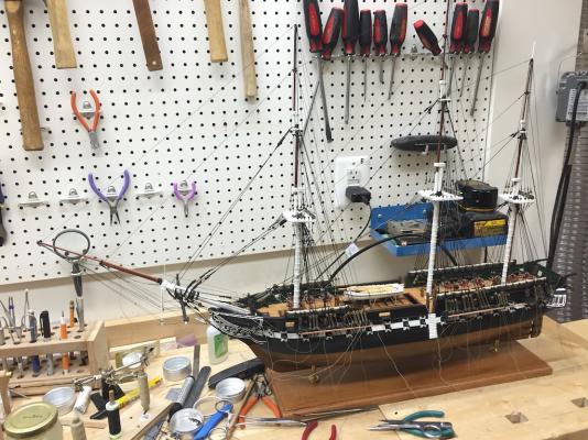
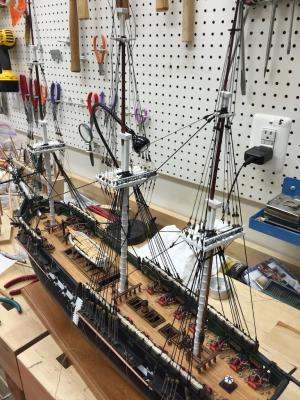
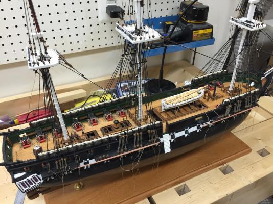
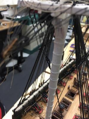
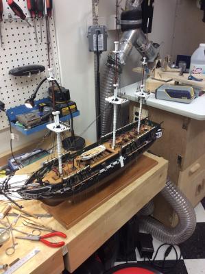
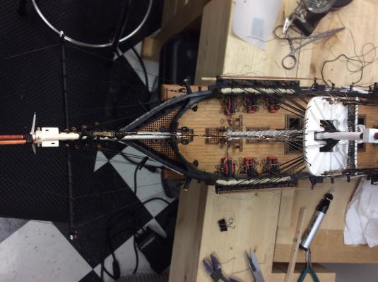
Milestone reached! The standing rigging is completely installed. I still need to perform final tensioning and dressing. Of course the rat lines are not part of this. I do not plan on running the ratlines until the interior running lines are installed. The mast alignment is pretty close. I will need to tweak the tensioning a bit to perfectly align them but they are not far out so this should be easily accomplished. I will be busy next week and will not be able to get to this, but a week for the lines to settle in will be fine as well. Sorry for the photo, The tools in the background make it difficult to see all the lines, but trust me there are there.
- 335 replies
-
- 6
-

-
- Constitution
- Mamoli
- (and 3 more)
-
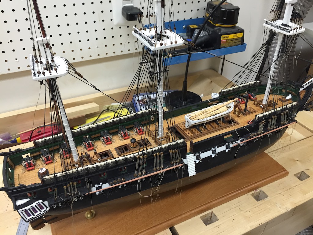
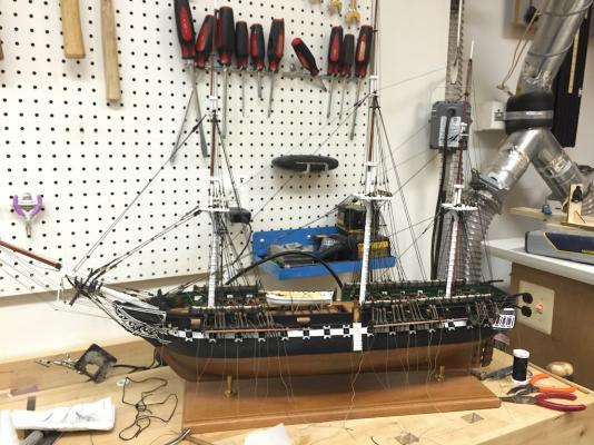
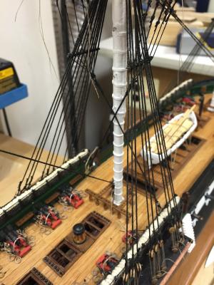
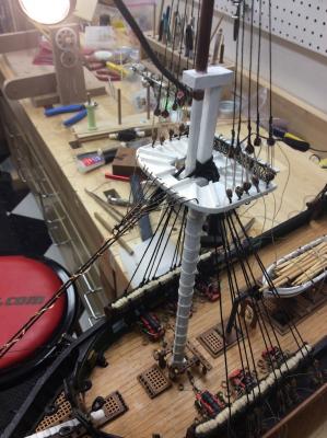
I completed the middle level of the standing rigging as well as all of the standing rigging for the mizzen. I hope to complete the standing rigging tomorrow. I still need to tension most of the lines and dress them. So progress is being made. She is getting big now. Funny how adding lines to the tops of the mast start to make her shape up.
- 335 replies
-
- 5
-
-
- Constitution
- Mamoli
- (and 3 more)
-
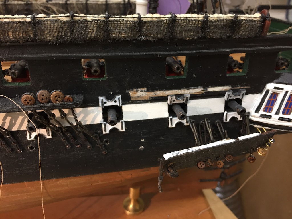
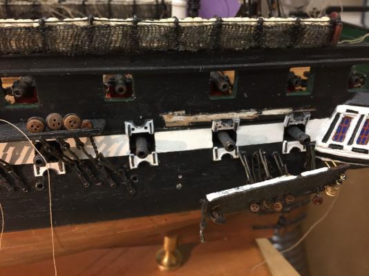
Lesson learned. When I was installing the channels I focused on where the front edges of the channels mounted according to the plans. What I should have been focused on was where the notches in the channels were and aligned according to those along with the cannon ports. As a result of this, the aft most channels were installed about ⅝" to far forward. This resulted in the rear canons being obstructed by the rigging. This became especially apparent after I ran the additional stays to the channels. I thought about this overnight and what could be done. If there had been room in the channels I could have cut new slots for the shrouds but there was not. There were only two possibilities. I live with this and hope no one notices. This would have been assisted by the whaleboats since they would have been mounted over the obstructed cannons, thus not easy to see unless you look down on the level of the cannon, or 2nd, I tear off the channel and move them in to the correct position. I chose the later. To remove the channels, I unlaced all the lanyards and taped the shrouds to keep them untangled. I took an exacto knife and cut along the hull at the rear of the channel to keep the paint from chipping. Then I took a pair of needle nose and carefully bent the channel up and down until it came free. I used a wood chisel to remove the forward part of channel support since it would no longer be under the channel, then I epoxied the channels back in their new position. Luckily I only had to remove one of the chain plates and move it aft on each side. I touched up the paint and let everything harden for a couple of hours. Then I replaced the shrouds and stays. Below are photos of one of the channels after removing it, and after the repair.

- 335 replies
-
- 7
-
-
- Constitution
- Mamoli
- (and 3 more)
-
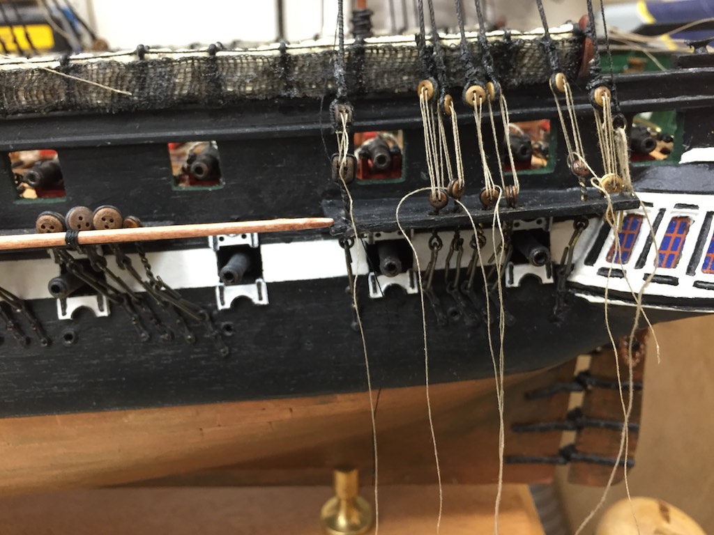
Today I added the mid-level forestays and backstays on the Mizzen. Tomorrow I will continue to work my way forward on the mid level stays. I did notice that the next to last cannon ports are blocked by the stays. I will look at seem adjustment but this is something I may have to live with. This may go back to how the chain plates channels were attached. I thought they were aligned according to the plans. I will look at it with fresh eyes tomorrow.
- 335 replies
-
- 4
-
-
- Constitution
- Mamoli
- (and 3 more)
-
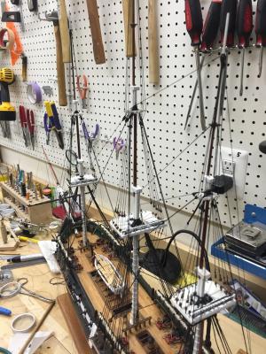
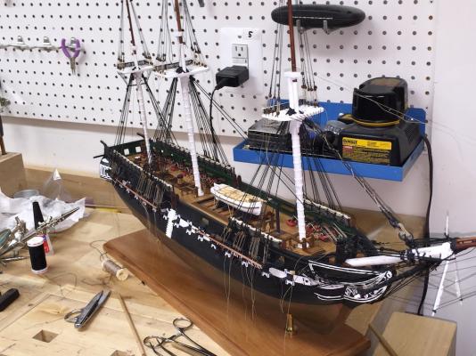
I completed the fore stay Bentinck shrouds today. I have started the alignment of the masts but not yet cinched the lower side shrouds permanently. The masts are close. I will start adding the upper forehand back stays tomorrow and start locking the lower shrouds in and dress the lines as I do.
- 335 replies
-
- 8
-
-
- Constitution
- Mamoli
- (and 3 more)
-
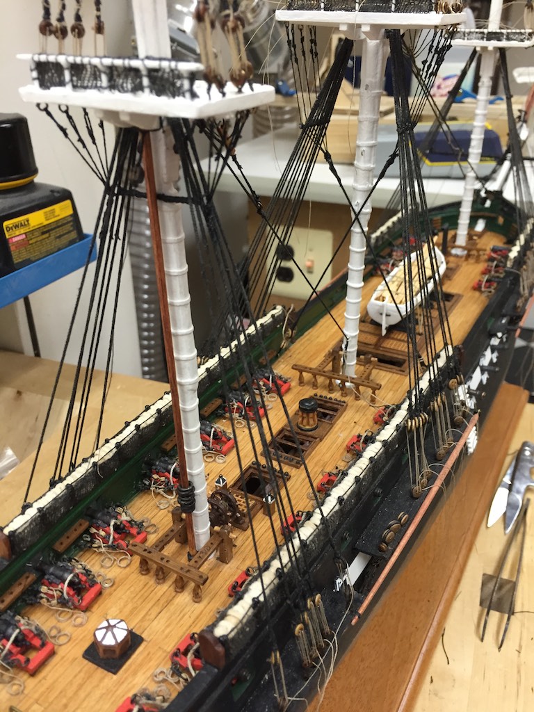
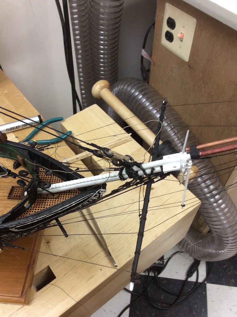
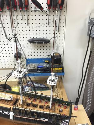
What I did was use the guides to hold the mast upright and mostly in position. Then I attached the lower shrouds. I am using these to perform the final alignment. Since the masts are not glued in, I can change the rake or side to side with the shrouds.
- 1,756 replies
-
- 2
-
-
- constitution
- constructo
- (and 1 more)
-
soldering torch vs iron
robnbill replied to rtropp's topic in Metal Work, Soldering and Metal Fittings
The solder goes where the flux is. There are a number of different flux solutions. What I use depends on what I am trying to do. I have a flux paste that I use if I am trying to get a wider smoother coverage. When the iron hits the flux it spreads. Anywhere the flux goes, I know solder will follow. There is also a solder/flux paste that comes in a syringe. This is great for targeting very small solders. For this I generally use the torch flame since a pass of the flame is all that takes the small amount of solder and paste to melt and adhere. I also find if I use the solder tip to warm the piece and melt the flux, then I can touch the solder to the tip and it flows off the tip and everywhere the flux just went. -
soldering torch vs iron
robnbill replied to rtropp's topic in Metal Work, Soldering and Metal Fittings
I prefer the micro torch for quick work on small parts. The torch also comes with soldering tips so if I need more control than the raw torch allows, I can attach the tip to it and quickly have it up to heat. I have both this and the electric torch but for a quick soldering for a small part, I reach for the micro torch kit. -
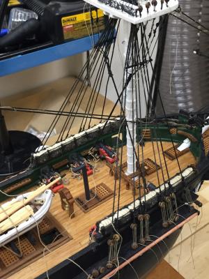
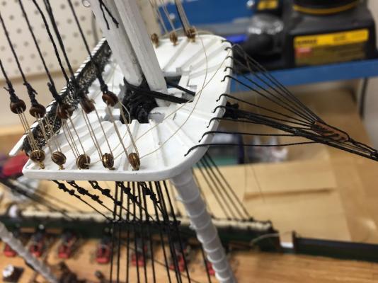
Today I was able to complete the Bentinck shrouds for the Main mast. I made the shrouds themselves by fully serving a line then serving a loop on one end and a deadeye to the other end. I know on the ship this is not exactly a deadeye, but looks very much like one over a standard block. I have attached some photos of the main with the Bentinck shrouds installed as well as some additional views of the crows feet. I will continue with the fore mast tomorrow, then start working on the upper mast stays and dressing the shrouds.


- 335 replies
-
- 4
-
-
- Constitution
- Mamoli
- (and 3 more)
-
There are also a number of plans out there if you want to make your own. I know everyone who has one of Alexi's machines loves them, there is a certain amount of satisfaction building your own. Serving is just wrapping a line with other line. This is done to protect the line against chafing. SO for shrouds, the forward most shroud on many ships was served full length. Another area is where the should pairs wrap the mast, this is also served. There are many areas of line that can be served. However, it is your choice whether to serve the line or not. At some scales, it would be difficult to see.
- 1 reply
-
- 5
-
-
The AOS has the crows feet in the configuration. I made mine based on those plans. Historically, by 1812, the British navy was phasing these out of their ships. It could be part of the 1812 configuration or not, it was probably on part of the original configuration given when she launched. 1812 is on the cusp of the change. I know there is a huge controversy over the accuracy of the AOS. The Mamoli plans did not have these, however, since there was a high likelihood it was part of the original configuration and in the AOS, and I liked the look, I made the change. They were fun to install.
- 335 replies
-
- 1
-
-
- Constitution
- Mamoli
- (and 3 more)
-
Thanks Mike. I told a friend tonight I see light at the end of the tunnel, I am just not sure how long the tunnel is. I am enjoying the rigging. I was't sure I was going to.
- 335 replies
-
- 3
-
-
- Constitution
- Mamoli
- (and 3 more)
-
I completed installing all the lower forestays on all three masts. I removed the zig zag line from the fore mast stays and redid it. I had looped the original line around the stays then seized it to the stays. This time I only zig zaged it between the stays and seized it. This is consistent with the main mast as well. I also completed the crows feet for all three masts. Tomorrow I will work on the Bentinck shrouds for the fore and main masts. Then I will start tensioning and dressing the upper stays. Here is a shot from the bow showing the stays and crows feet in place. There are still a number of temporary lines on the bowsprit. These will be removed as the upper stays take the support for the bowsprit.
- 335 replies
-
- 5
-
-
- Constitution
- Mamoli
- (and 3 more)
-
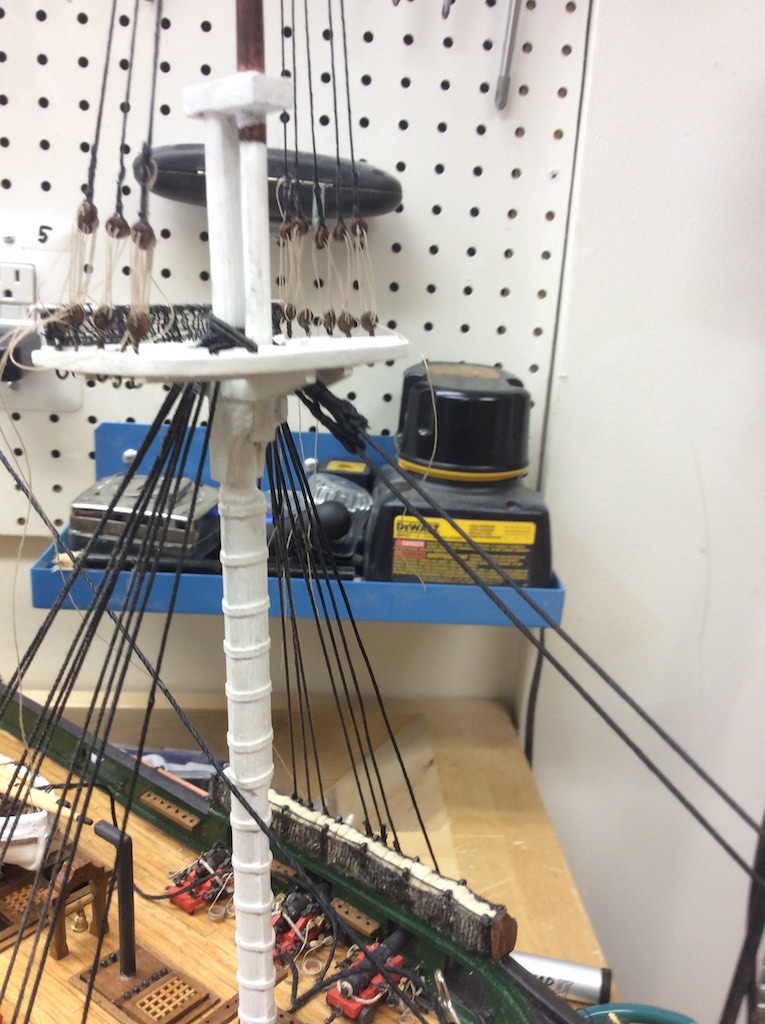
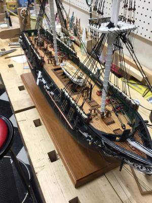
I was able to get the main mast forestays completed and installed today. I have not yet done the crows feet or zig zag line between stays. I do however have a better photo of the crows feet on the fore mast as well as an overall shot of where the Connie is sitting now. I do have a bit of clean up on the paint where the dye in the lines has rubbed on the white. That should be fairly easily done with a cue tip and some acetone.
- 335 replies
-
- 7
-
-
- Constitution
- Mamoli
- (and 3 more)
-
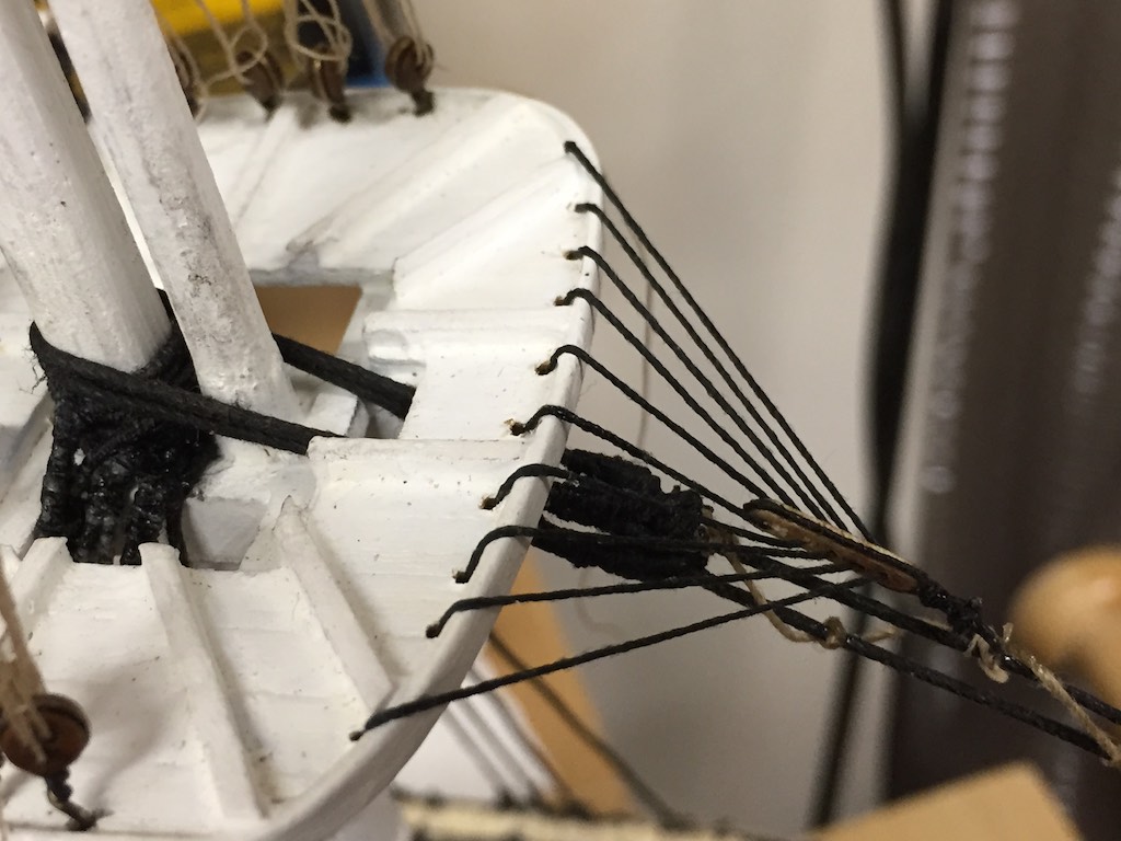
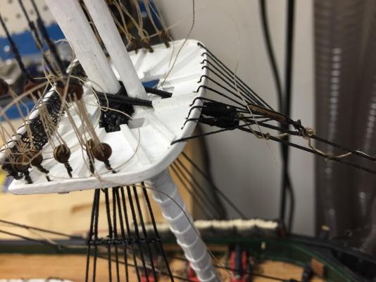
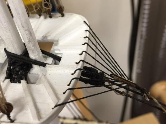
Here are some close ups of the crows feet on the foremast. I was able to create a small block to run the lines through. I am pleased the way it came out. I also spent some time this morning dressing the lines along the lower part of the Bowsprit. I put a temporary forestay to the tip since the lower lines were tending to deflect the tip slightly.
- 335 replies
-
- 4
-
-
- Constitution
- Mamoli
- (and 3 more)
-
I installed the first two forestays on the lower foremast today. I played a bit with how I wanted to build the mouse on each stay. I tried carving a small dowel with no luck. Finally I used a heavier line and served the line to name the mouse. I used the normal size serving line to serve the loop on the end of the stay and the loose end. I rove the mouse end to the mast and after fitting the metal eye to the end I served this to the lower end. I performed this on both the upper and lower stays. Then I ran the zig zag line from the lower part of the stays to the top. One decision I made to go off the Mamoli plan was to install the crows feet to the fighting top. I drilled the holes and attached it initially with a ring to the forestay. However, I want to try creating a block for the crows feet tomorrow and reinstall the crows feet. The ring can be a back up should I not be able to get the block made the way I want it. I have attached some photos of the ship after the stays were installed but before I rigged the zig zag line or the crows feet.


- 335 replies
-
- 4
-
-
- Constitution
- Mamoli
- (and 3 more)
-
Well if it is any consolation, a good soldering iron will last a long time.
-
Wow, what we miss as a Mac household!
-
Thanks. I will wait to add the pins until I start actually belaying lines. I was able to compete the side shrouds today. None are dressed. I plan on installing the lower fore and back stays first, then once the rake is correct I will dress the lower shroud lanyards. So as of an hour ago, the Connie has all her masts installed! Now it is all just tuning! Right.
- 335 replies
-
- 1
-
-
- Constitution
- Mamoli
- (and 3 more)
-
Welcome to the Connie builders - and to the smaller set of Mamoli Connie builders. There are a couple of build logs on here for the cross section. I would add to not reject out of hand the faux copper bottom Mamoli has. While you certainly can use real copper foil on the bottom, then you have to decide to patina it, clear coat it, or wait years while it goes through the darkening process. The Mamoli green plates were designed to create a faux finish by first, being separate plates, then secondly by the finish you apply. The directions tell you after you apply the plates to the bottom you lightly sand them then coat the bottom with a copper paint, followed by a thin green stain. This creates the mottled copper/copper patina bottom. You have a lot of control over how green or copper you want your bottom to be. I actually like the way mine came out. However, I can see the attractiveness of applying copper foil as well. Anyway, I know you will enjoy your build as we will who will be following your log.
- 113 replies
-
- 2
-
-
- constitution
- mamoli
- (and 1 more)
-
I suspect you have a bad soldering iron. If your iron isn't getting hot, then it cannot heat the metal you are soldering. Both the soldier and the metal you are working on have to be at the same temperature. That allows the solder to free flow over the piece. If your iron has started to take a long time to melt the solder, get a new iron.
-
Thanks Henry. It would be fascinating to see photos as the progresses through this revolution.
-
I do have the book and have been using it or the rigging. I forgot there was a belaying plain the back. Thanks!
- 335 replies
-
- 1
-
-
- Constitution
- Mamoli
- (and 3 more)