robnbill
-
Posts
841 -
Joined
-
Last visited
Content Type
Profiles
Forums
Gallery
Events
Everything posted by robnbill
-
 I actually have 100 belaying pins. Certainly more holes in the belaying pin racks than that so I will need to do some reading ahead to see where I need pins and what holes I want to leave open. Suggestions?
 -
From the Connie's site. Public Tour Hours SHIP TOURS ARE FREE OF CHARGE - ALL PERSONS AGE 18 AND OLDER MUST PRESENT A VALID FEDERAL OR STATE-ISSUED PHOTO I.D. OR PASSPORT TO BOARD THE SHIP. October 20, 2014 - March 2015: OPEN Thursday - Sunday, 10 a.m. - 4 p.m. CLOSED Monday - WednesdaySHIP TOURS ARE FREE OF CHARGE - ALL PERSONS AGE 18 AND OLDER MUST PRESENT A VALID FEDERAL OR STATE-ISSUED PHOTO I.D. OR PASSPORT TO BOARD THE SHIP.
-
The group that supports the Connie giving tours in period costume is also responsible for suppling the wood to the museum. If you contact them, they could probably arrange to get you a piece of the wood. Popeye2sea is part of this group and pointed me in that direction for mine. They ask for you to consider giving a small donation to their group since it is non-profit and supports a great cause. The link is below. www.1812marines.org Seaburd, in March 2015, the ship is going into dry dock for a number of years undergoing a major refit. So if you wait until summer, you will probably be out of luck in getting aboard her.
-
Thanks. I guess I need to count how many pins I have and work from there.
-
I have a question. I looking over the various logs I noticed some models have their belaying pins installed pretty early. Others wait until much later in the process. What is the best practice on this. Should I look at installing the pins now or wait until the standing rigging is complete?
-
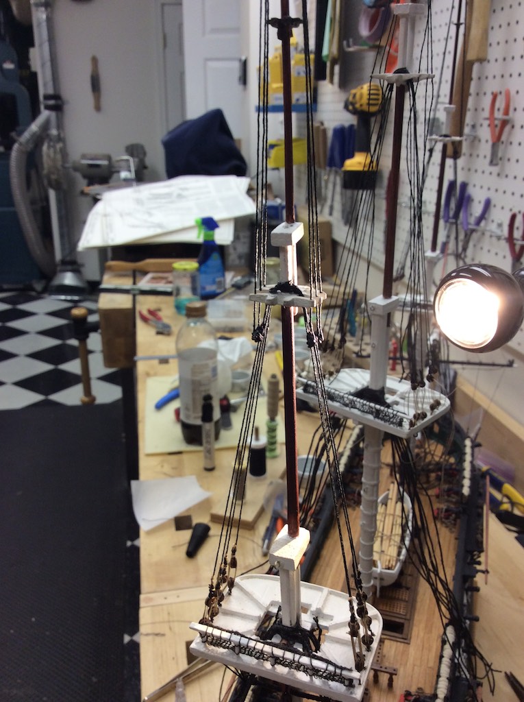
I finished rigging the lower main mast shrouds today. I also did a preliminary tensioning to see how the masts aligned. I did not cinch the lines off but wanted to start tensioning. I have decided to rig the fore mast before I rig the upper shrouds on the main and fore masts. This will allow me to align the masts with the lower shrouds before I start working on the upper shrouds. I will rig the mizzen then start installing the fore and back stays for the lower masts.
- 335 replies
-
- 3
-

-
- Constitution
- Mamoli
- (and 3 more)
-
USS Constitution by galf
robnbill replied to galf's topic in - Kit build logs for subjects built from 1751 - 1800
Looking at the photo of the Connie, it appears the nail heads are less than an inch. Probably ¾" to ½" if the boots are as close to them as it appears. If that is the case, ¾" would equate to about .25mm, assuming you are working on the MS version of the Connie at 1:76. So it would be difficult to scale realistically, however, there are many modelers out who have added the nails, they are just not in scale. It is a look and provides the appearance of having the nailed plates to the bottom. So this really is up to you. Add nails knowing they will not be in scale, or no nails. Look over the logs to see how others have accomplished it. My Connie is 1:93, so she would have been too small. Also Mamoli used a completely different technique using wood to copper the bottom. So I can't be of much help there. There are many ships built here that have copper plating. -
This is looking good. You might want to apply finish to the lower gun decks before you build around them. They will be difficult to get to later.
-
USS Constitution by galf
robnbill replied to galf's topic in - Kit build logs for subjects built from 1751 - 1800
This link from the Navy states there is 120 - 150 nails per sheet. http://www.history.navy.mil/USSCTour/manuals/ConstitutionCopperSheathing.pdf The photo below, taken from the 92-96 restoration, shows a single plate in the lower right, still attached and you can se the nail patterns on it. The link to the site is: http://www.hazegray.org/features/constitution/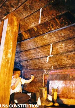
-
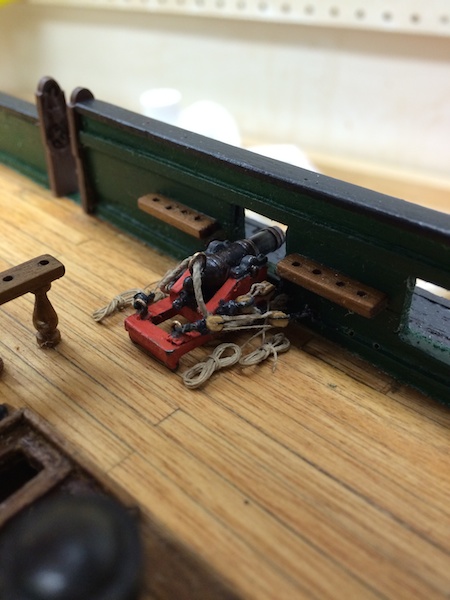
I read somewhere where it described the sailors flaking the line back and forth over the deck in a somewhat zig-zag pattern. This could be done quickly and would allow for the line to run freely when the cannon recoiled. Unfortunately, I think it would make for a weird looking model. The flemish flake would certainly allow the line to run freely, but I question if they could or would do this under battle conditions firing the cannon as quickly as they could. That is why I settled on the coil. I know it is still problematic fort knotting, but having the flemish flakes makes it look like they are ready for inspection rather than battle. So if the cannon were not in firing position, I think the flemish flake would look great. Anyway, that is my two cents.
-
Thanks. I am beginning to see her shape up. Tomorrow I will be tackling the Bentinck Shrouds (off plan) since that is likely the way the futtock shrouds were done. They certainly were done in the British Navy at the time so I suspect the American Navy as well. It looks like the only the forward and main were done that way so I used a catharpin on the Mizzen. Previously I rigged the deck rings for the shrouds. Now I just have to implement it. I will post photos once I have it done. I am assuming that I should not run the forestays until all the side shrouds are done. On this I am following the Mamoli plans (for the order at least).
- 335 replies
-
- 2
-
-
- Constitution
- Mamoli
- (and 3 more)
-
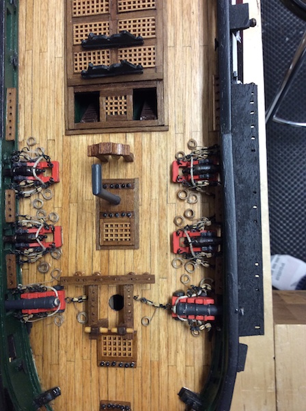
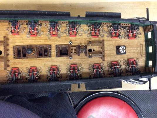
I agree that the guns would be trained on the target. I also think that this might look at bit strange on a model. However, I could imagine where the guns would be loaded and run out and they would all be perpendicular to their gunport. Then as their target came into line, the crews would use the tackle to adjust the aim. All that said, I would play with it until you like it and go with that. One thing that was pointed out to me (by Chuck) was since my guns were also pointed out and ready for firing was the lines coming from he blocks were bundled neatly and laying to the side. This would have caused them to knot terribly once the cannon was fired. So I ended up just coiling them (not using the flemish flake), but just coiled since they were ready to fire. I also placed the canon both before and after rigging and took lots of photos. I felt that allowed me to see the ship better and study what I liked or didn't before actually attaching and gluing the cannon to the deck. Here are some photos of both the canons how I had them originally bundled and how I ended up with them installed.


-
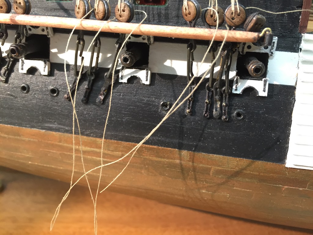
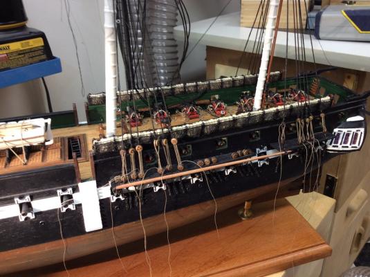
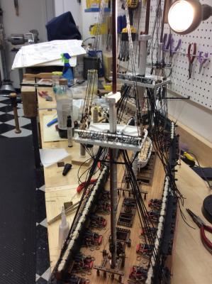
I thought I would take a break and finally post a photo of where I am on the Connie. I am continuing to rig the lower main shrouds. I had a small setback yesterday when I noticed that months ago when I rigged the deadeyes to the chainplates I inadvertently missed one of the deadeye holes. So yesterday I noticed as I was rigging that the two sides did not match. It was pretty easy then to see my mistake. Since the chains were one of the components that was short in the kit, I had to make a new pair. I did this using brass wire. First I bent a small piece into the lower chain plate. This I soldered in the middle, then drilled three holes. One in each end and one in the middle. Then I took a second piece of wire and bent the connecting chain. After blackening I attached it to the ship and touched it up with black paint where the brass showed through. I have attached a photo showing the new chainplate installed. It is the second from the right. I am continuing to work on the main deadeyes and should have the lower main shrouds completed today.

- 335 replies
-
- 8
-
-
- Constitution
- Mamoli
- (and 3 more)
-
Welcome Fletch, I too am currently building a Connie. Targeting the 1812 version will be fun and challenging. As CaptianSteve mentioned, the real Connie is headed into dry dock this spring for a multiyear rebuild I don't think they have published a list of everything they are going to do but interest is great to see what they will be doing on the bow and stern. One thing you will find as you go through the logs here is everyone who has worked on her or is thinking about working on her has strong opinions on what she should be configured like. However, it depends on the source of material that each builder has determined will be the definitive source for them. Some of the areas that you will find a great deal of discussion around: 1) The stern - the configuration of windows, the number and layout, 2) The stern - The ornamentations on the stern, some paintings have a much more elaborate stern than that on the ship currently 3) Gun ports - Do they have covers or not, if so, are the split or solid. 4) Gun stripe - What color should this be. There is evidence this strip was painted yellow at least one period during her life, 5) Bow - What did it look like. Originally she had a Hercules figurehead, which was destroyed in a collision during her first voyage in the Med. There was also a period she had a figurehead of President Jackson, but that was in the 1830's so probably not something you would want. For most of here life she has carried the simple fiddlehead like she has now but I do not think the exact pattern of it is known. 6) Rigging - Each captain decided the rigging that they were going to have on the ship. Indeed, the sources around the Connie suggest that she was considered a slow ship for a number of years. So masts have been shifted, yards have been changed, and the general sail plan has changed depending on the captain. 7) The bowsprit - The hull model shows steps from the forward deck up to the bowsprit. Most models do not as the current ship does not. There are steps up the bowsprit but stop when they get to the bulkhead. 8) Armament - How many guns and of what type did she carry in 1812. 9) Ships Boats - These changed over the years as they tended to get destroyed pretty easily. Most models show her with 4, but she carried many more than that at times. The extra boats were usually stacked over the main hatch. The bottom line is you will need to do your research and decide which source you will follow. Each source has it's advocates as well as it's detractors. For every point above, and many more, you will find those who feel very strongly about each side. No one knows who is totally correct since there is no documentation that answers any of these points with absolute certainty. So build your Connie with the choices you decide represents what you think she looked like. It is your ship. If you do have specific questions about a particular area, ask. I guarantee you will get a great deal feedback and opinions on what each of us thinks. Then you will have to decide what to do. What you will not get is someone to tell you this is exactly what she looked like. The Constitution Museum historians are there to help. I have reached out to them a number of times and they have been helpful. You can also obtain some of the Connie's wood from the museum and use it in your model should you be interested in having a piece o the old girl in your ship. The Connie is a fun and challenging ship to build and should provide you with many hours of pleasure. Take your time, it will probably be a multiyear effort to complete her. At least it has been for most of us. Welcome to the forum. I look forward to your build and what you will be adding to the knowledge base of the ship.
- 47 replies
-
- 10
-
-
That is interesting. I was able to preview it, including the pages the description and digram were on.
-
I am continuing to work on the Main Mast lower shroud deadeyes. The process I have found to work best for me is 1) Serve the first deadeye to the shroud and laced to the lower deadeye - this sets the level for the remaining deadeyes. 2) Bend the next shroud around a set of bent tweezers to locate the next deadeye. This allows me to tension the shroud while locating the deadeye position, 3) Make a loop in the shroud and tie just above this with the serving thread. 4) Push the deadeye into the loop. 5) Use the tweezers to hold the deadeye under tension and adjust the loop accordingly. 6) Server the shroud just above the deadeye. 7) Recheck and perform final adjustment for shroud length (using the tweezers again) 8) Rotate the deadeye for hole alignment 9) Use small amount of CA to lock deadeye and serving to shroud. 10) Trim loose end of shroud and add additional serving (and lock with CA) 11) Lace the deadeyes with the lanyard and loosely tension. 12) Do a shroud pair on one side then rotate to the other side. Seems like a lot of steps but it is working for me better than the wire jigs. Currently I am about half way through the lower main shrouds. Once I complete them, I will dress the upper shrouds. They are already laced but not fully tensioned.
- 335 replies
-
- 4
-
-
- Constitution
- Mamoli
- (and 3 more)
-
Do a google search on Dog-Bitch Thimble and you should find an excerpt from The Anatomy of Nelsons Ships that describes it as well as has a drawing. http://books.google.com/books?id=_I8AqFfhvn0C&pg=PA237&lpg=PA237&dq=dog-bitch+thimble&source=bl&ots=HrkgQ4vHPj&sig=DduiOcb2GKF3uMLc56uV5k21klk&hl=en&sa=X&ei=deBQVKHWKszdsAT5o4KADQ&ved=0CC0Q6AEwBA#v=onepage&q=dog-bitch%20thimble&f=false
-
Agreed. I learned my lesson years ago cutting Cocobolo without proper dust and respiratory protection. Now I can't use that wood at all. Luckily the Hardwood store bought back the wood I had not used yet. This was my old house shop so my partner had to actually clean and wipe everything down before I could go back into it. I had become highly allergic to it. So when I was building this shop out I actually had engineers at Penn State Industries design the dust collection system. You are absolutely correct that too large of ducting with an underpowered motor would not work. There are also losses of suction at every bend and fitting due to friction within the system, so I looked to the professionals to help me with my system. They called my shop the bowling alley because it is long and narrow. Since the system is fully ducted throughout my shop, I also have drops that are sweeps so I can sweep the dust on the floor into them. I also have 4" flexible hose that connects to rolling sweeps and handheld to assist in cleaning around the benches and under saws where the dust still manages to slip by. Penn Industries was great to work with and their design has worked well. I just installed the Sawstop with their under and overhead dust collection. They claim the high 90's in collection. I will know once I start cutting the wood for the Eagle but that is a bit out since I am working on the rigging on my Connie now.
-
Interesting on the PVC. I actually have a fine dust filter that filters the air leaving my cyclone to .5 Micron. When I installed my system ( well over 10 years now) I decided to put spiral metal ductwork in. Primarily because of the throughput since it is a larger circumference, but also because it was stronger than standard metal ducting.Outside of the Cyclone, I have Delta air handlers that filter ambient air down to 1 Micron. I have two hanging in the workshop since it is long and narrow. Each is set to change the air in a 20x20' room up to 18 times per hour. Also, since sanding is one of the worst culprits for dust, I have a 4'x3' sanding table that I can hook into the dust control system that pulls a strong downdraft on the top. So I can place the object I am sanding on the table and the dust is all sucked downward and into the cyclone. My biggest concern with my shop was it is in deep the basement of our house so any dust that escapes would find itself throughout the house. I way overbuild the dust collection system so I could counter that. So far it has worked like a charm.
-
All those are good ideas. Han I was planning my workspace I knew I have to install a good dust collection system. So each of my machines is piped thorough the duct work to the machine. When a gate is opened on the system the collector automatically comes on. I also installed two ambient dust collectors like Mike has (Delta brand on mine) and they recall the air in the shop to remove fine dust that did not get sucked into the collector. The cyclone certainly makes the shop cleaner since it removed the majority of the dust created when using a tool. However it is the fine particulate that does not get removed since it leaves the blade while it is away from the cyclones suction that causes the most issues for health as well as the fine dust that collect on everything. Ambient collectors go a great deal forward in removing that from the air. On mine, I can set them on three different speeds and a timer so they can be turned on and continue to run after I leave the shop. The cyclone runs while the tools is running. The ambient collectors continue to run after until the dust is no longer in the air. Together each part of the DC system operate well and keep the dust to a minimum. One other thing to keep in mind, While PVC makes easy work of running a pipe between the Shop vacuum system and a tool, it also creates it's own hazard. As the dust moves through it a high speed it creates a static charge. Under the right conditions this static can cause s spark that can ignite the dust in the system. Running a ground wire through the pipe end to end solves this problem.
-
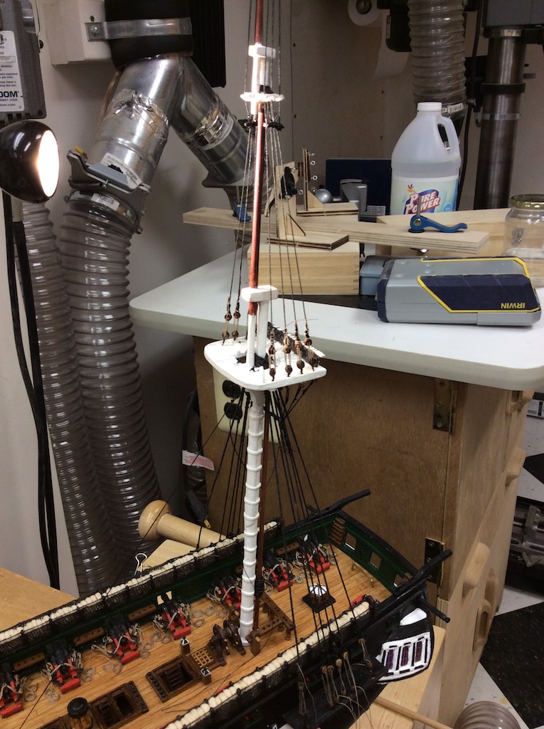
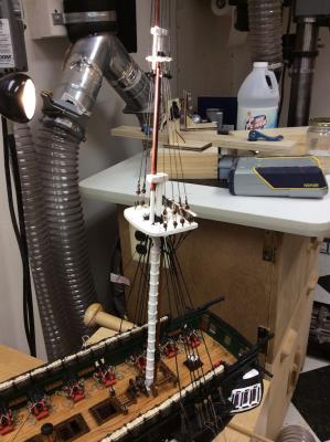
I drilled a small hole in the foot of the main mast and inserted the end of a needle. This gave me just enough grab to stabilize it. I only had to do this on the main. The others seem stable enough for me to rig. I will know shortly. I have finished the mizzen and will be starting the main next.
- 1,756 replies
-
- 2
-
-
- constitution
- constructo
- (and 1 more)
-
Your build is looking great. I think you will find that all manufacturers have their positives and negatives. I would look at the aspects of the build you want to do, then look for any build logs of that model in the forums. Then you can decided if the model is right for you. One suggestion on your current build is to sand the metal parts to remove and molding marks or flashing. Keep up the great work.
-
I completed rigging the Mizzens shrouds today. I dressed the upper shrouds but will wait dressing the lower shorts until the other masts are in place and the rig is stretched out a bit. The upper shrouds have been tensioned for awhile now. Next I will move forward to the Main.

- 335 replies
-
- 5
-
-
- Constitution
- Mamoli
- (and 3 more)
-
That might be a bit of a challenge since it uses a double acting bolt. When you tighten the knurled knob on the top of the jig it swells the fitting riding in the miter effectively locking the jig in both directions. It could be replaced but it would require some ingenuity.
-
It is Minwax Golden Pecan. The difference in colors is the wood from the Mamoli kit. The decking is Tanganyika and the coamings are walnut. I do use a Walnut stain touchup Pen as well on areas of the walnut that might need touching up.
- 335 replies
-
- 2
-
-
- Constitution
- Mamoli
- (and 3 more)