
.JPG.ca33079f5815b861e67b9c2cccd37982.JPG)

Blue Ensign
-
Posts
4,572 -
Joined
-
Last visited
Content Type
Profiles
Forums
Gallery
Events
Everything posted by Blue Ensign
-
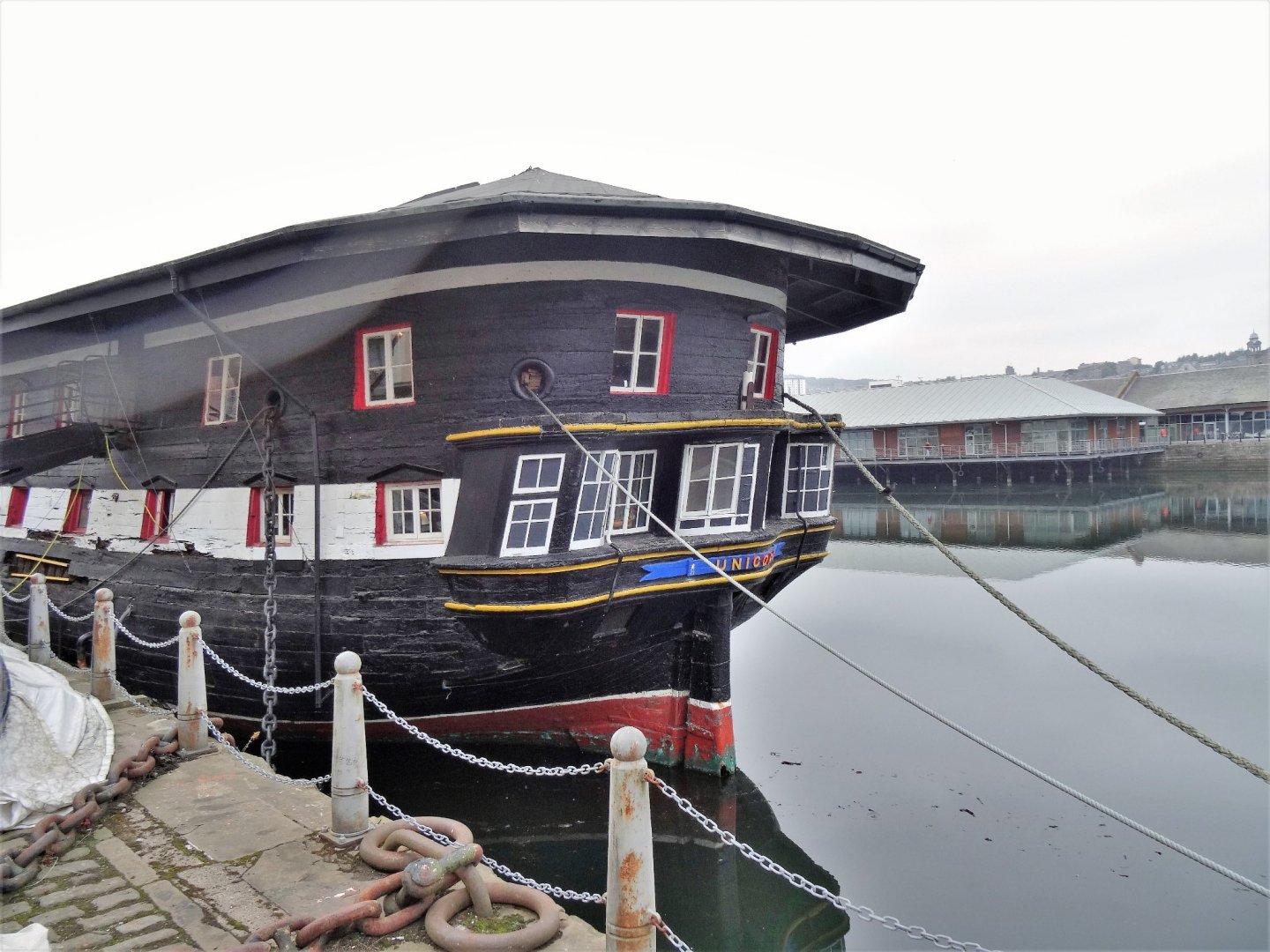
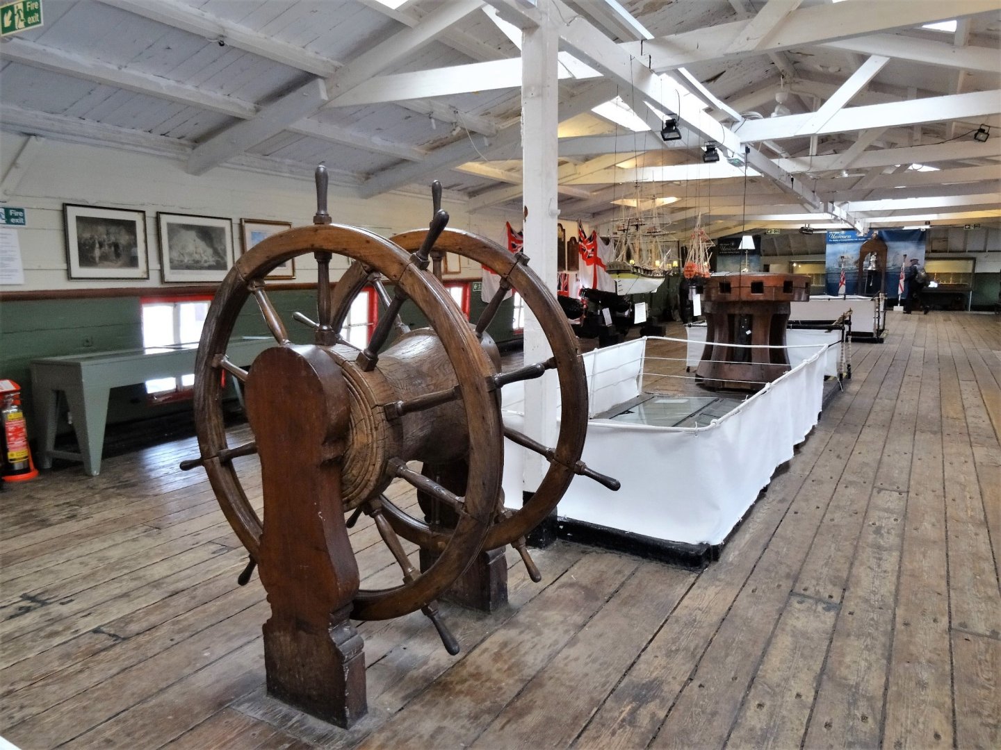
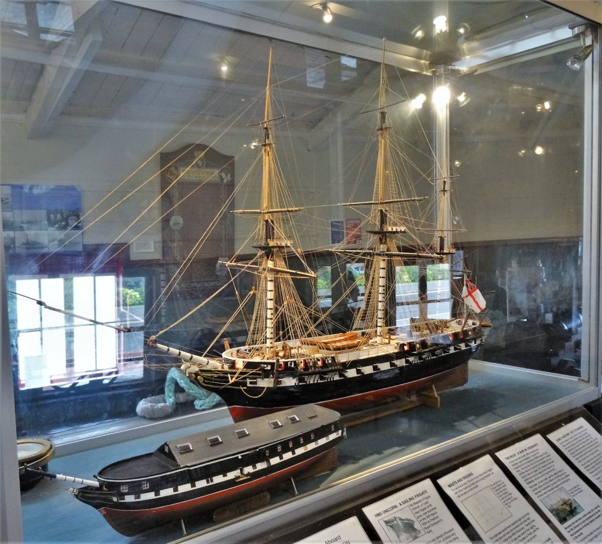
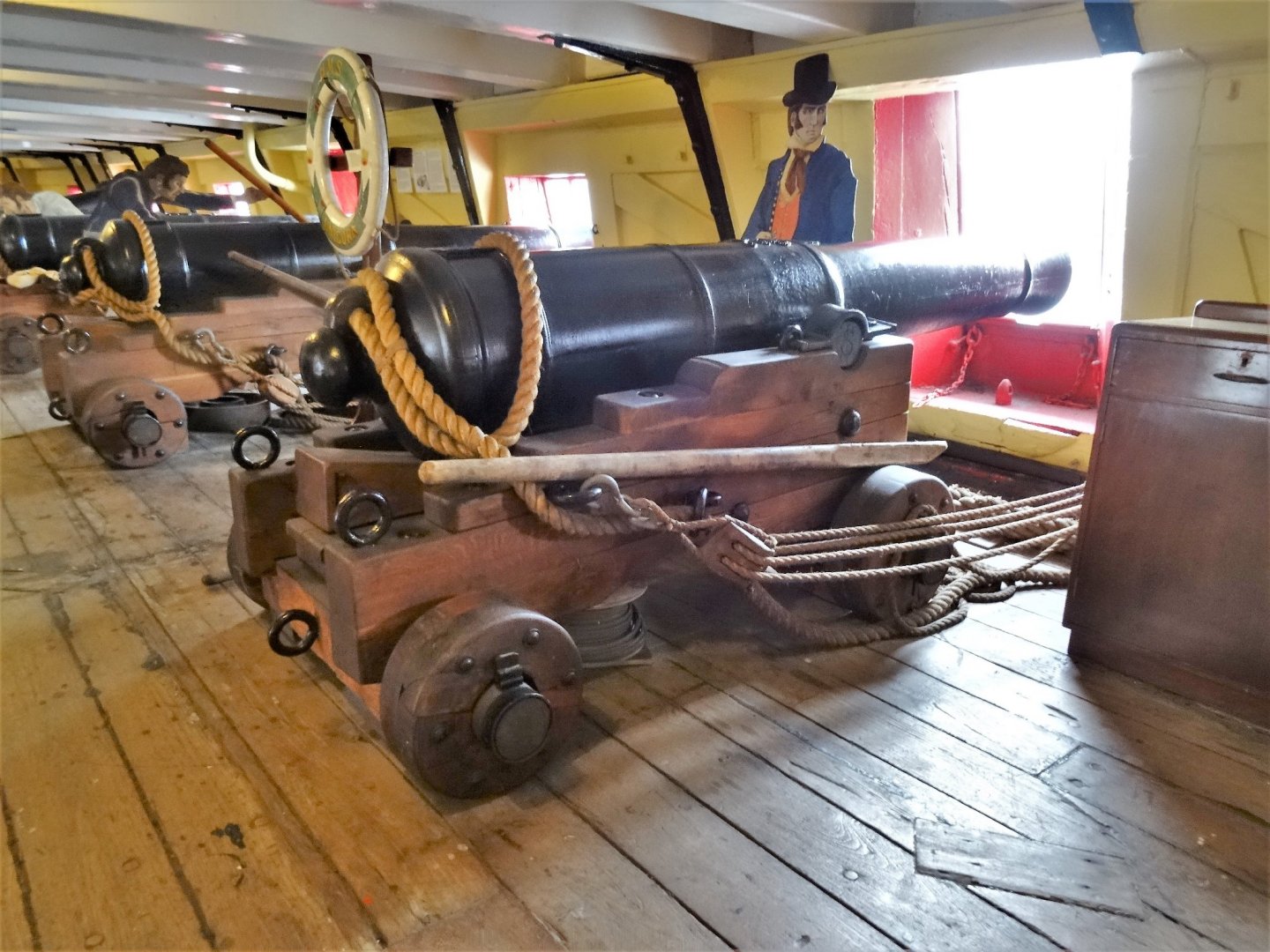
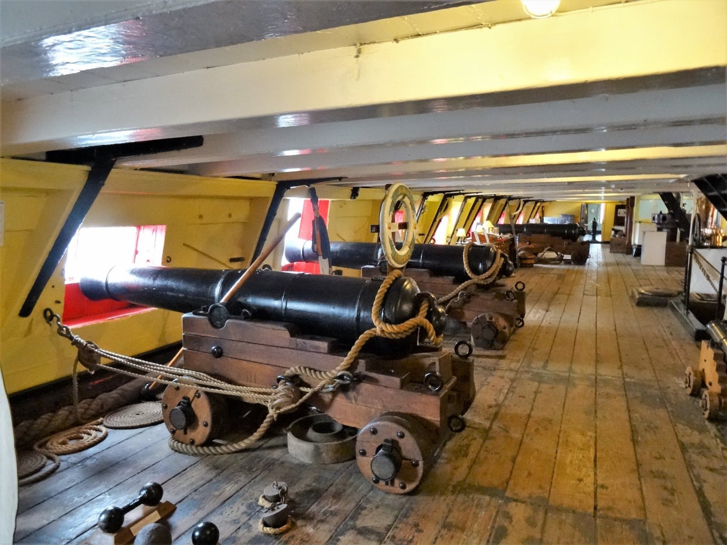
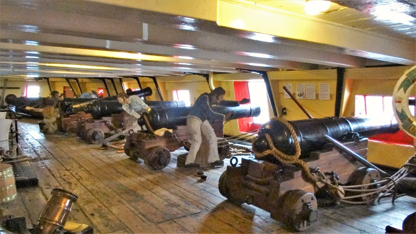
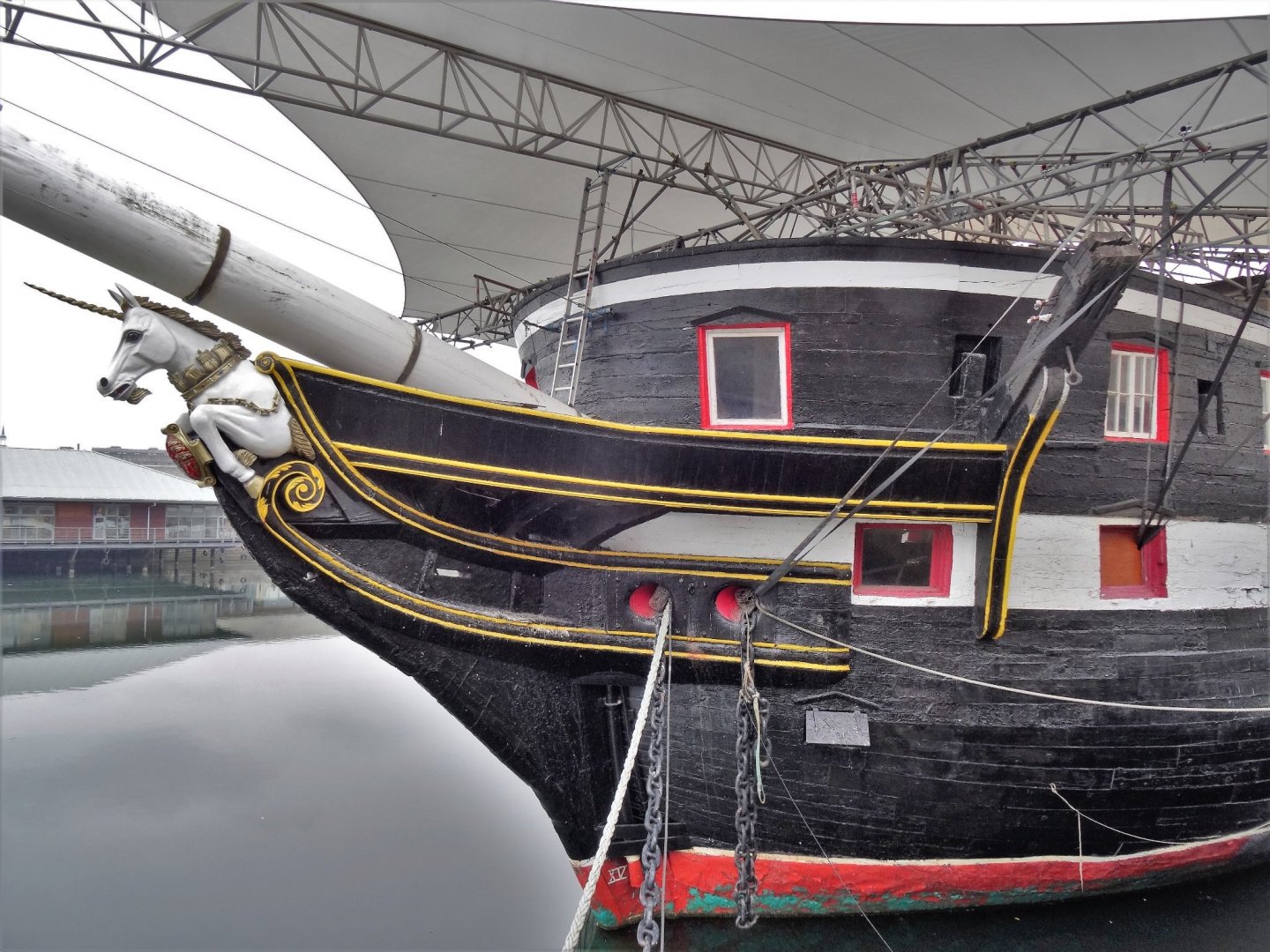
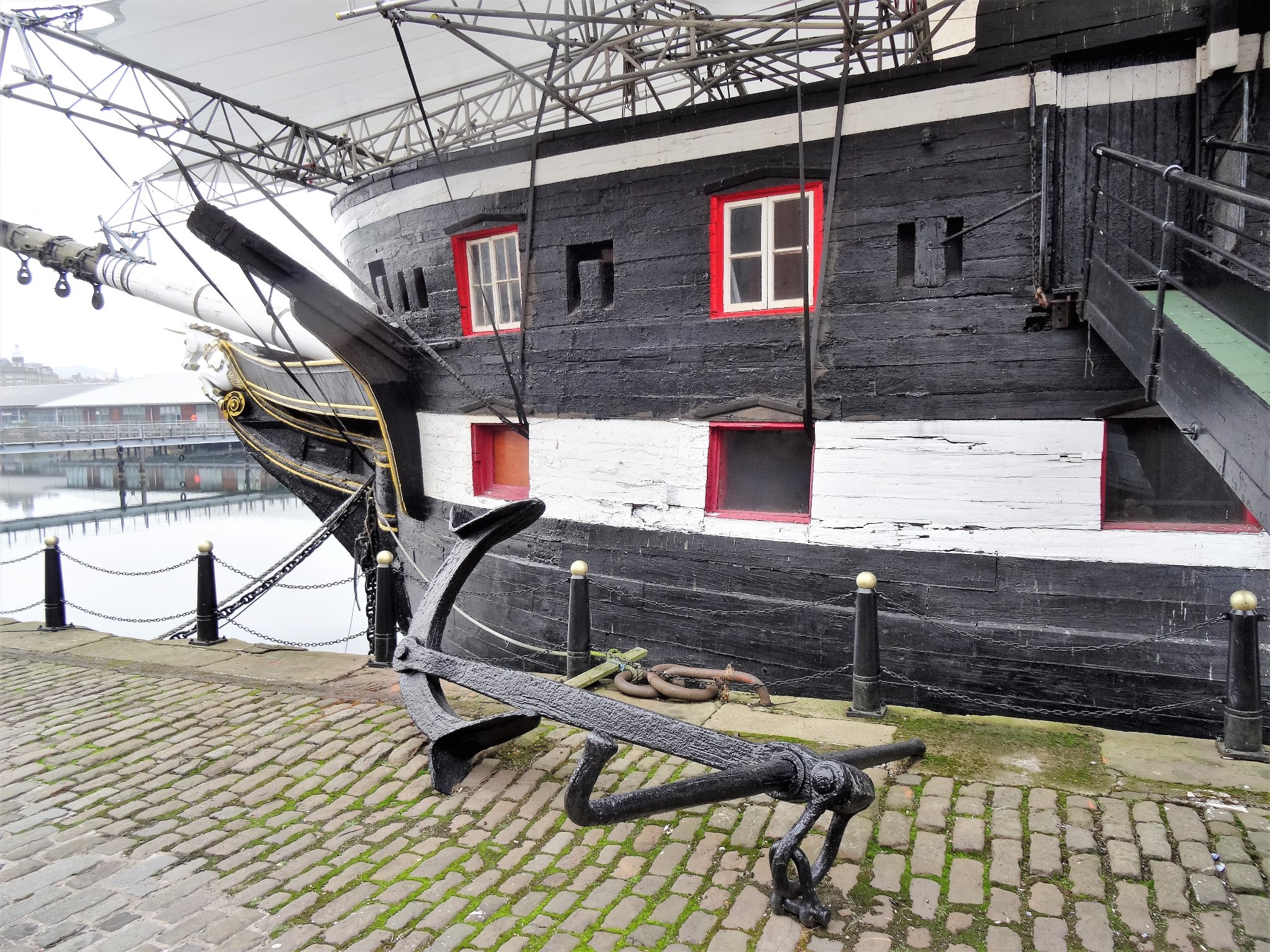
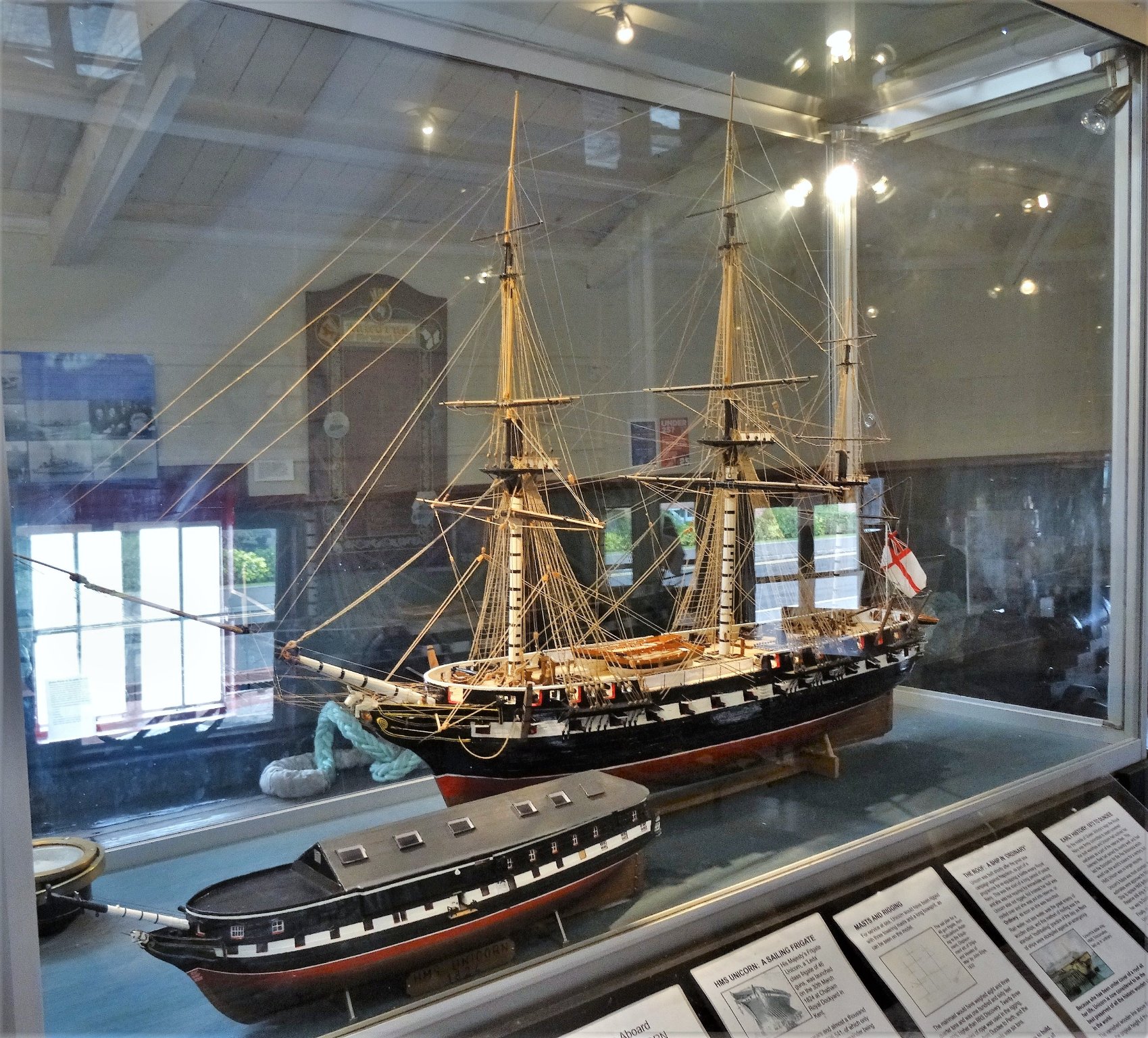
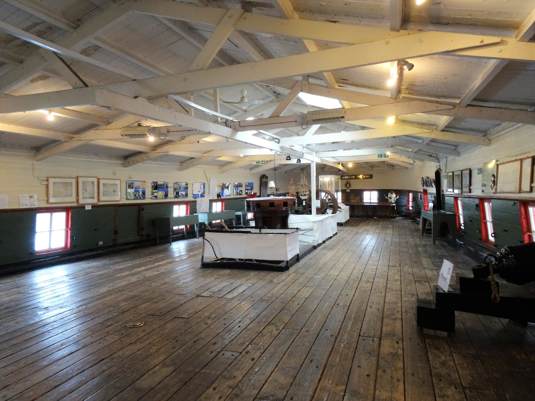
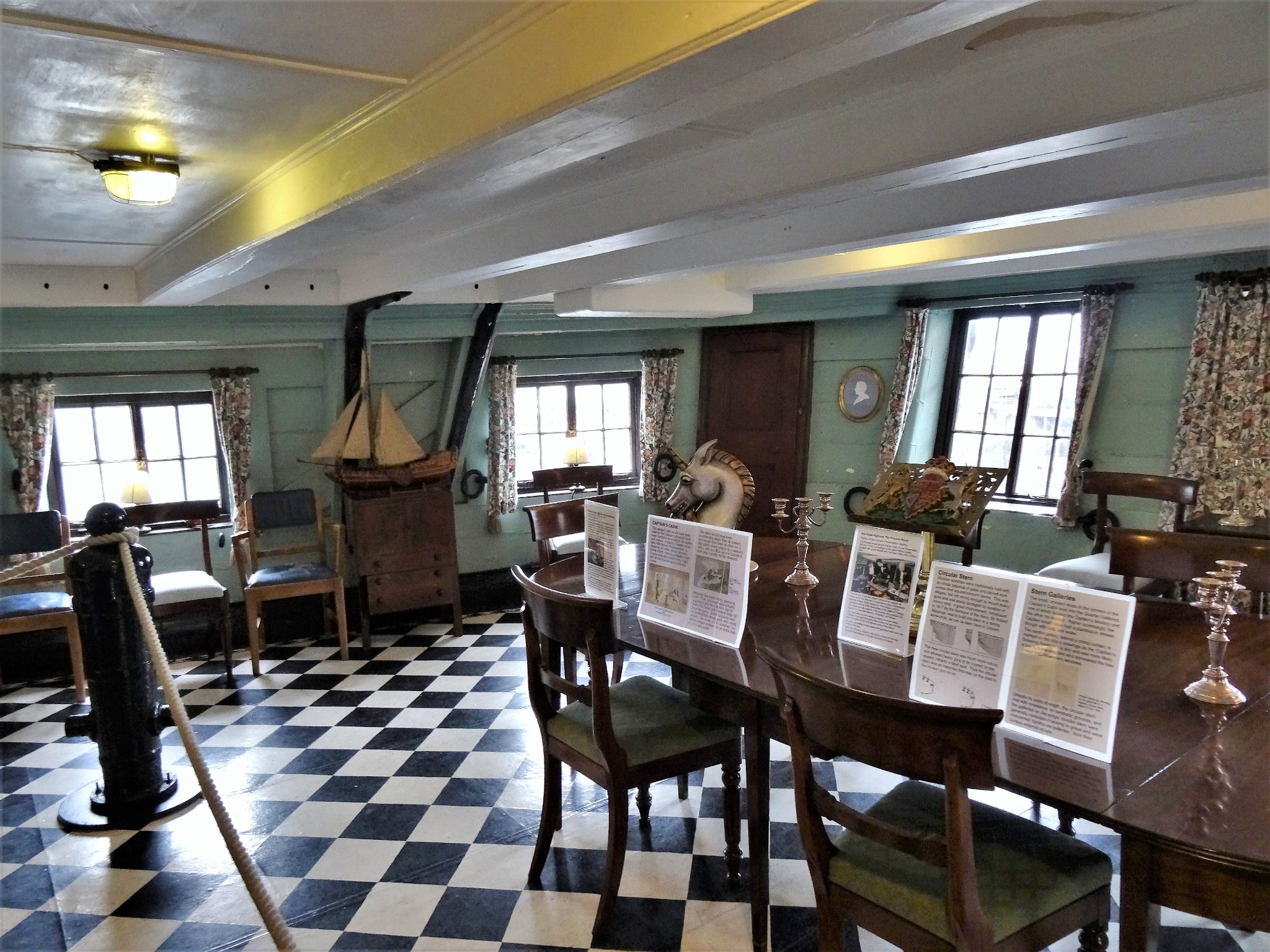
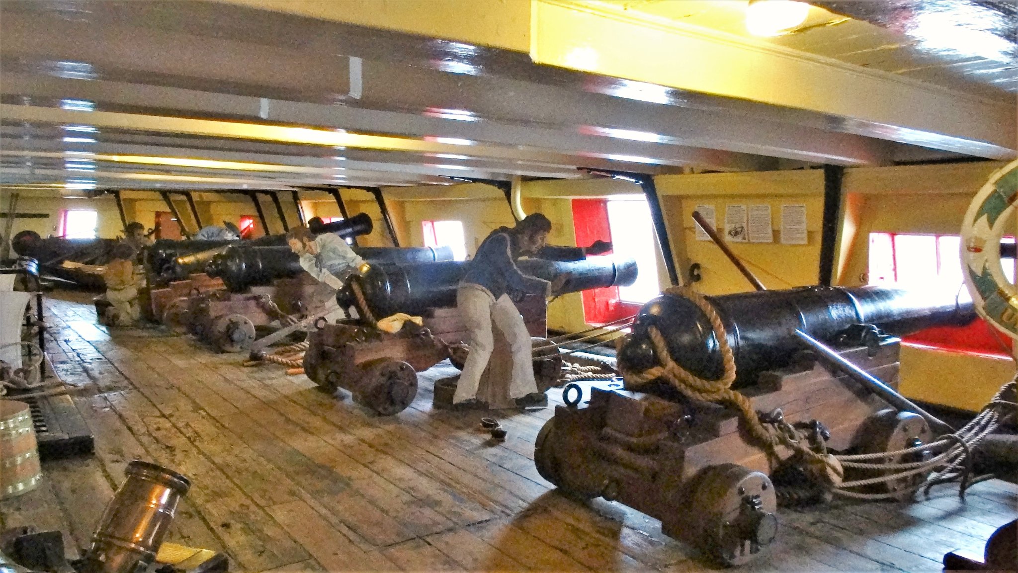
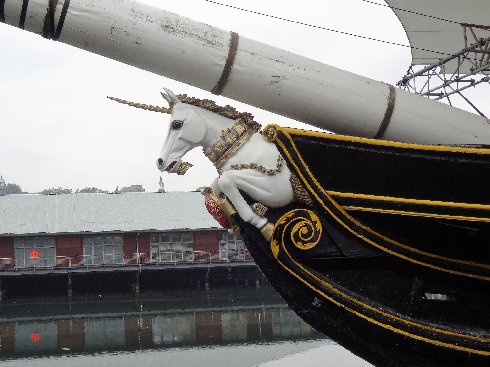
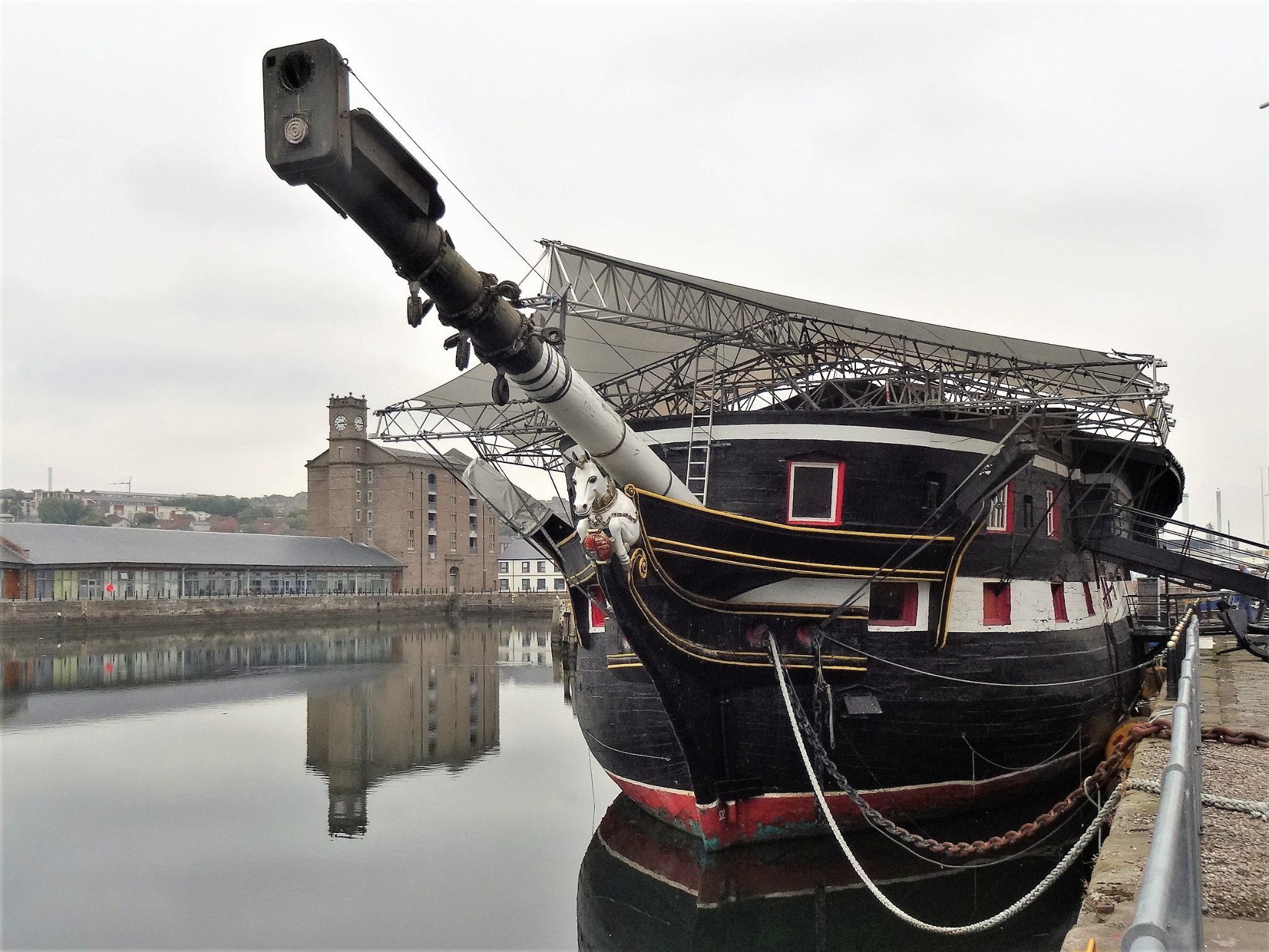
 I enjoyed a visit to HMS Unicorn back in 2013, I do hope she is preserved, she is an important historical artefact. Here's a few photo's I took at the time which may be of interest. B.E
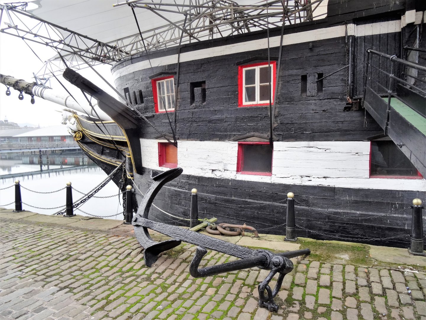


- 13 replies
-
- 8
-

-

-
- HMS Unicorn
- preservation
- (and 2 more)
-
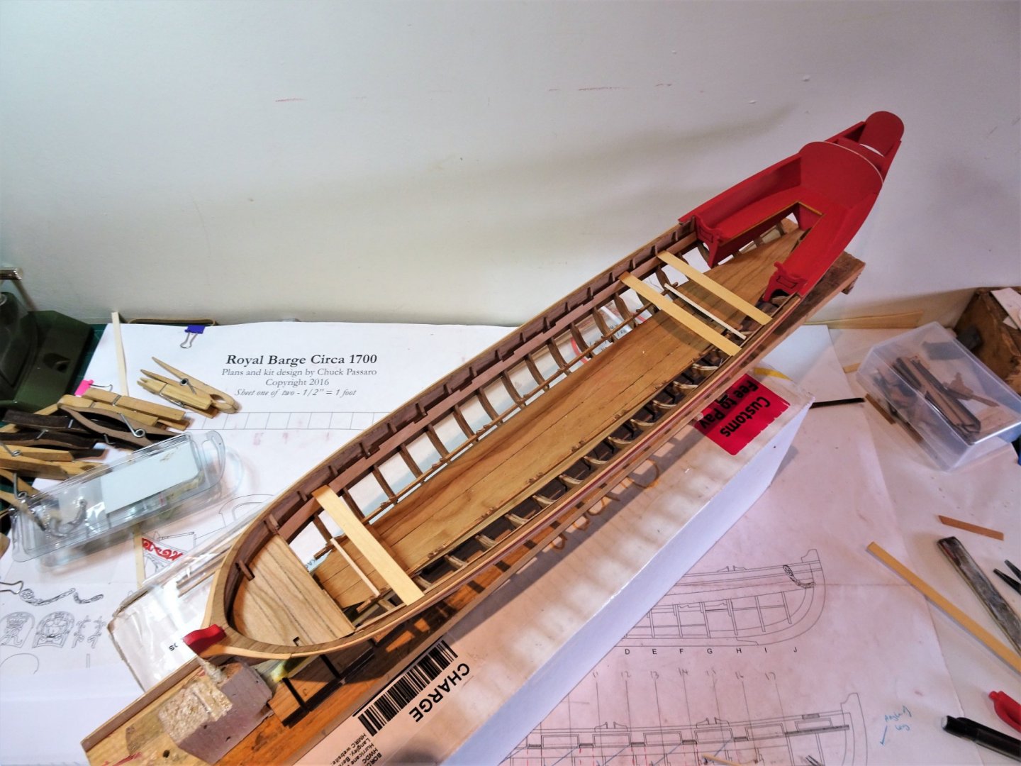
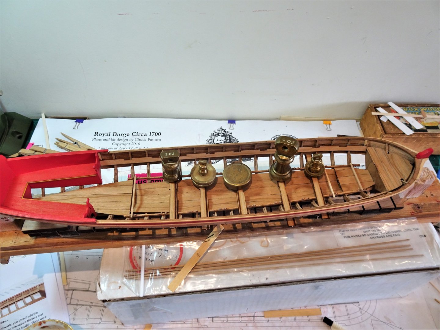
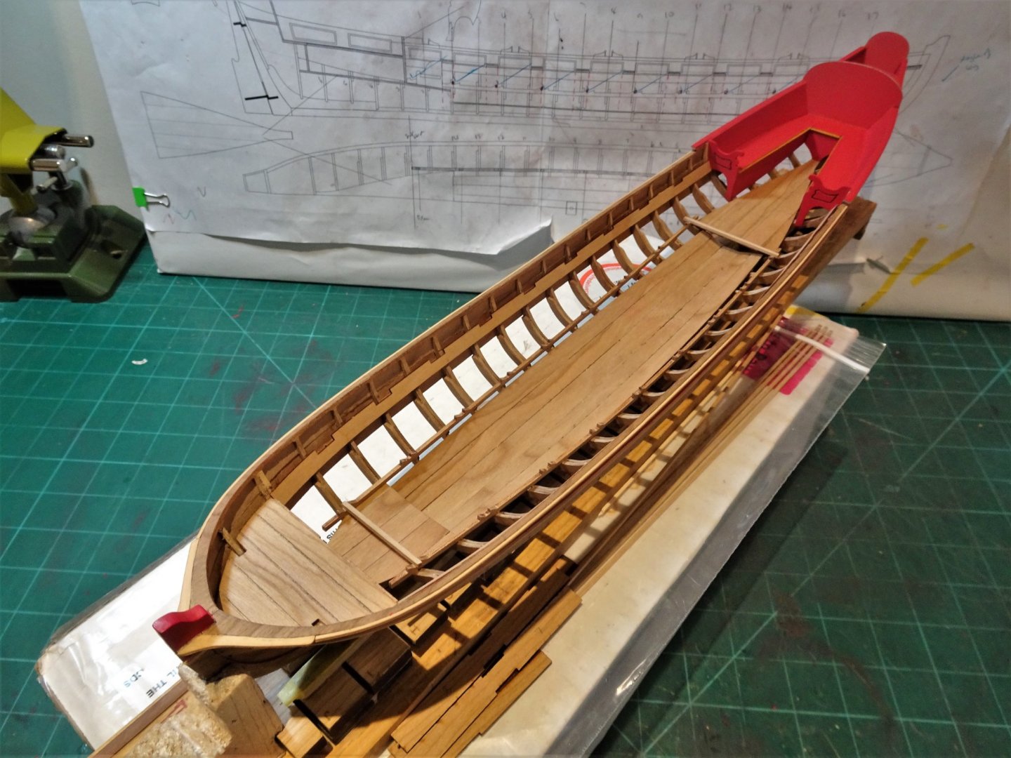
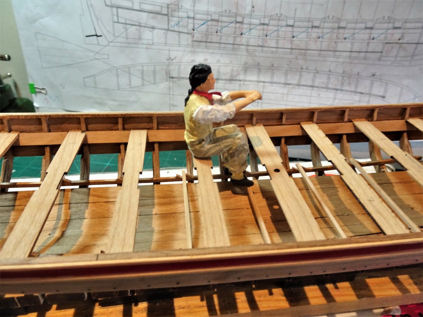
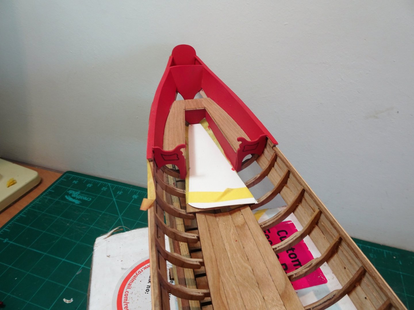
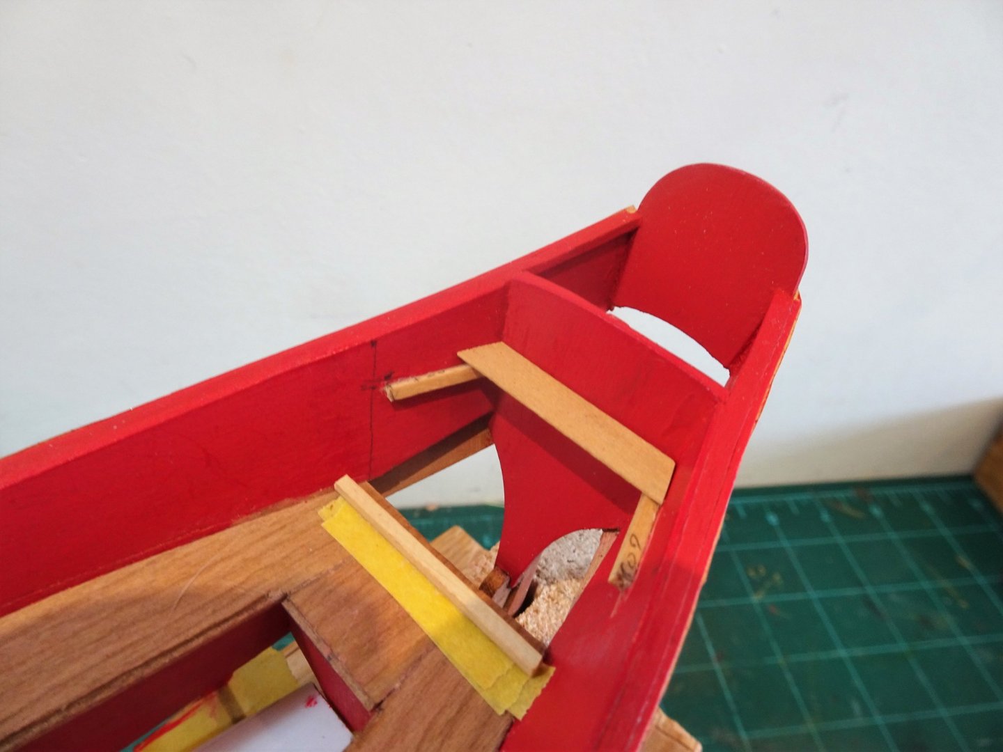
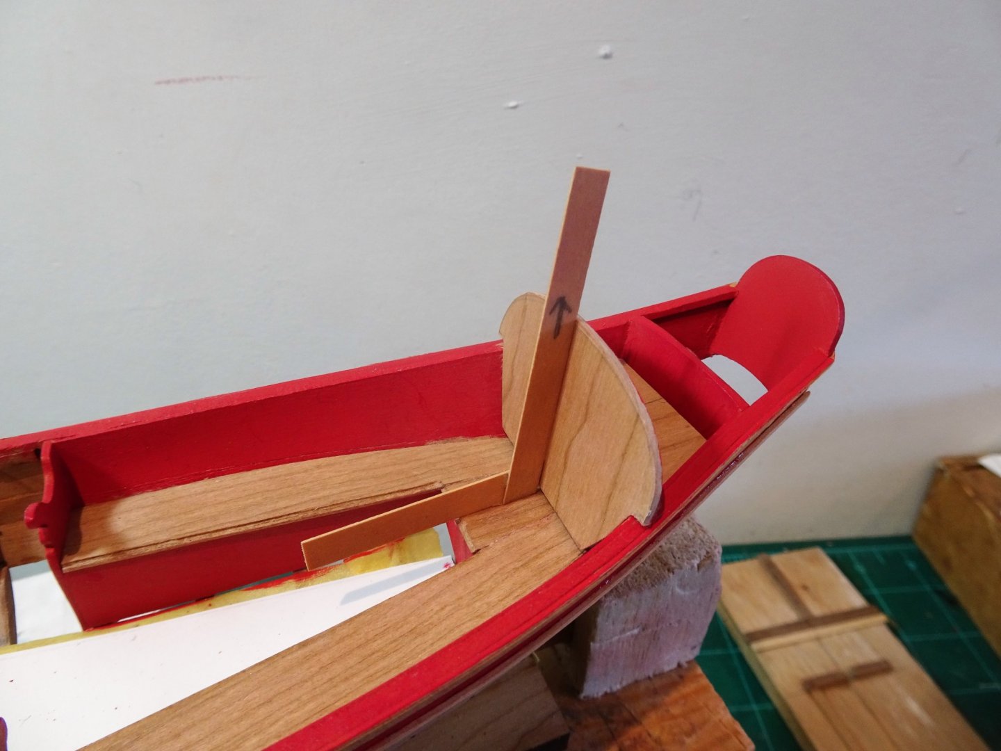
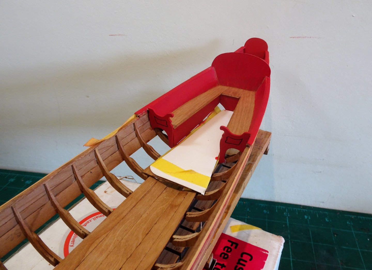
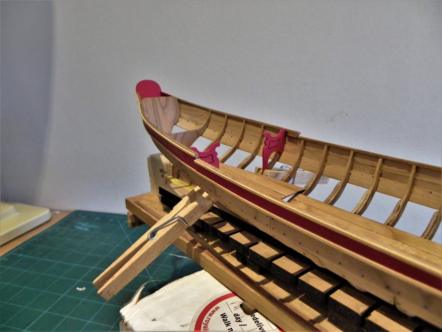
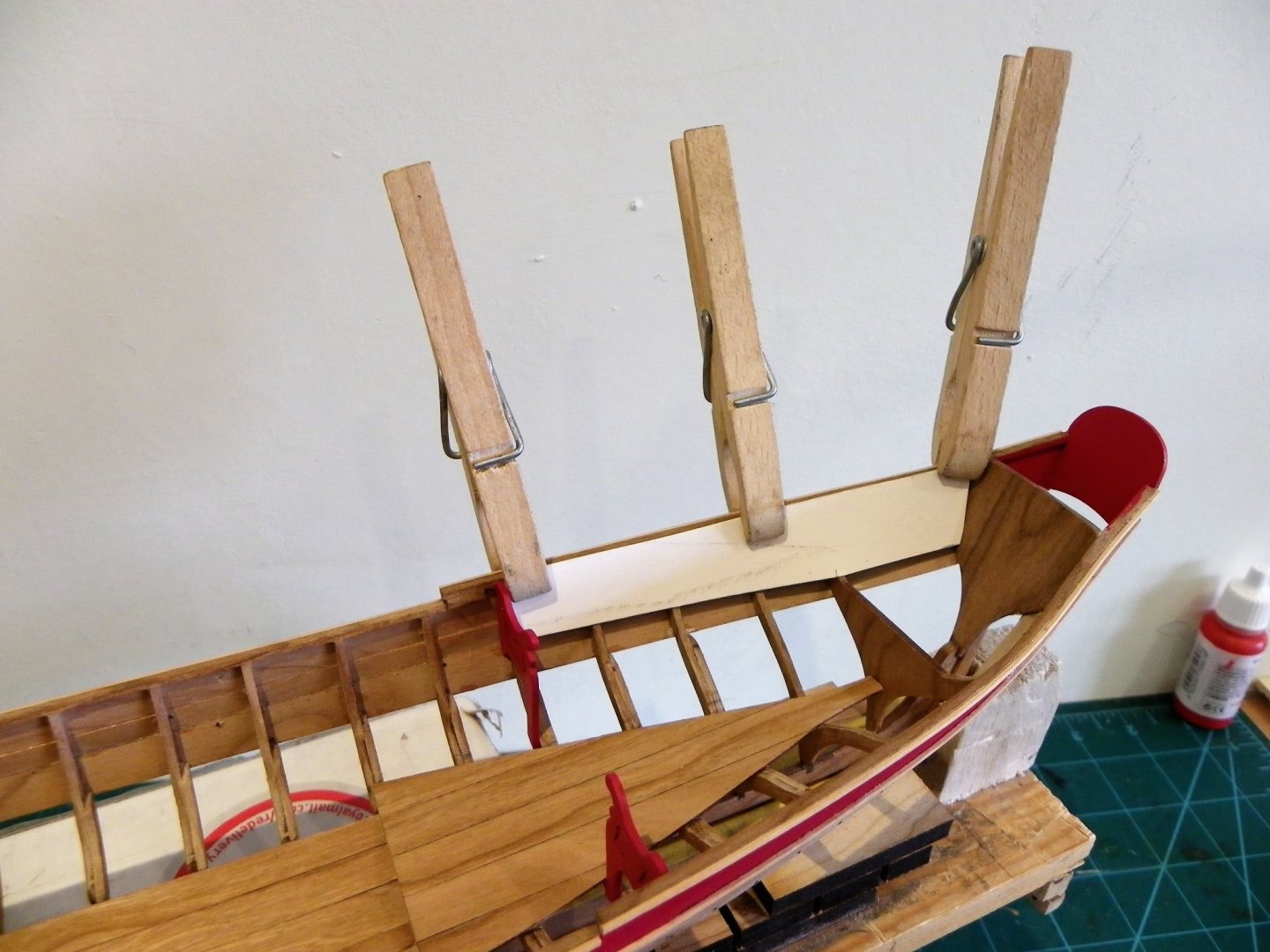
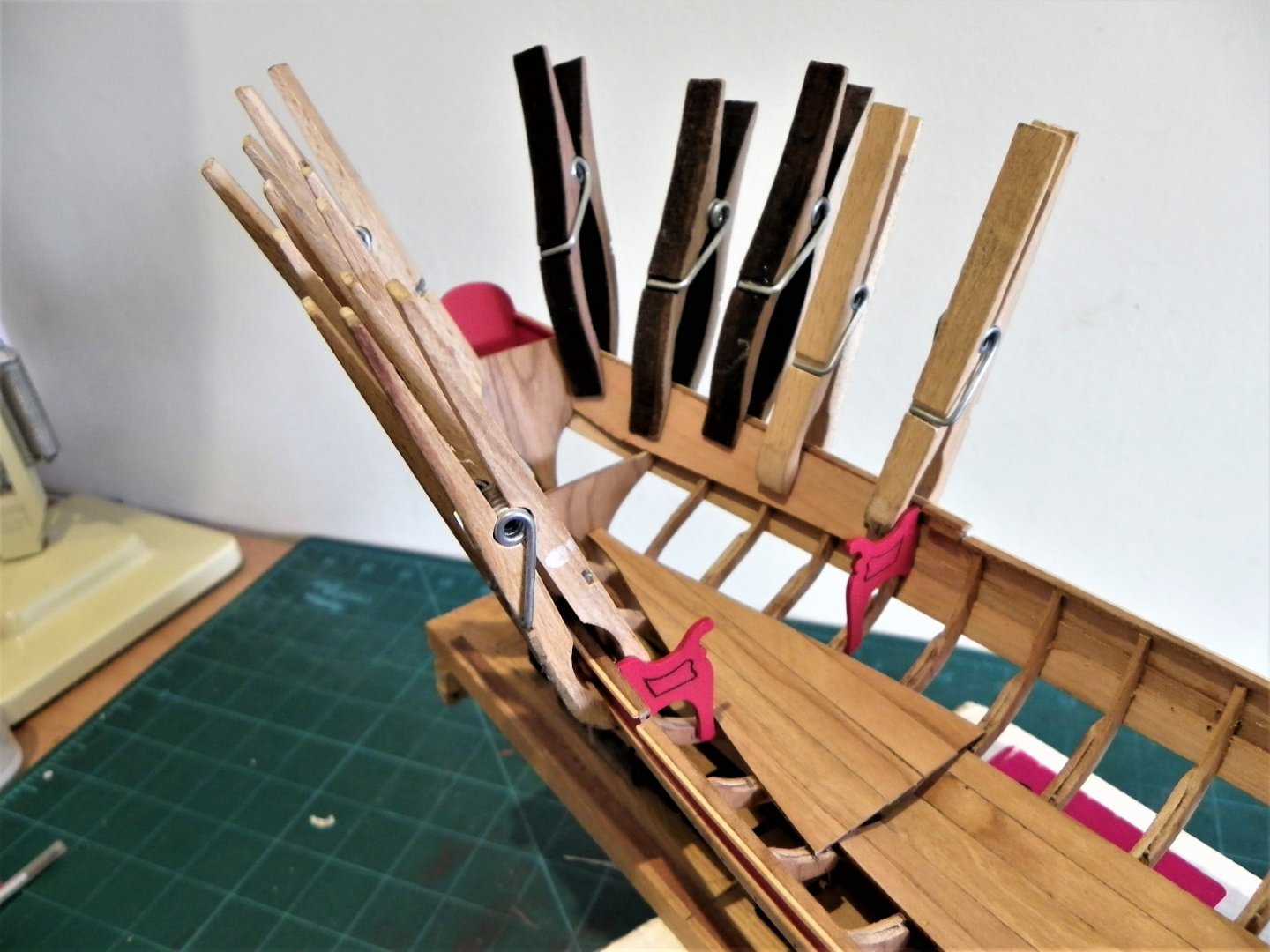
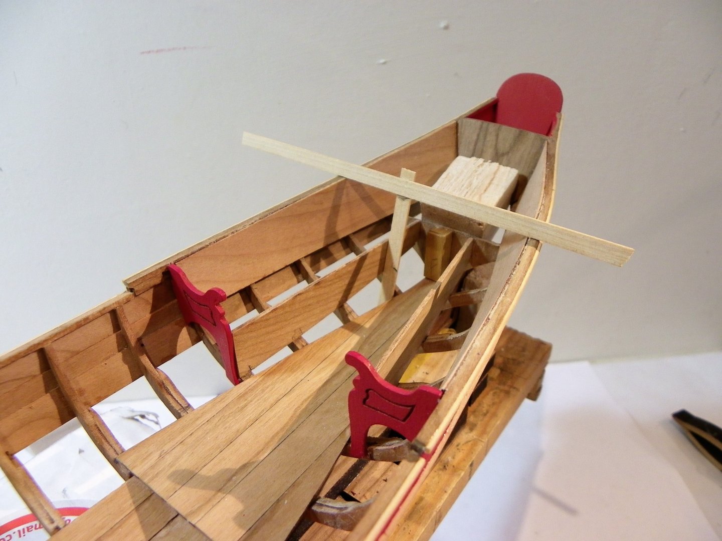
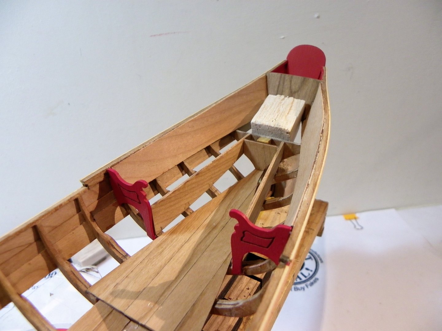
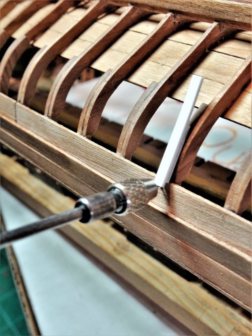
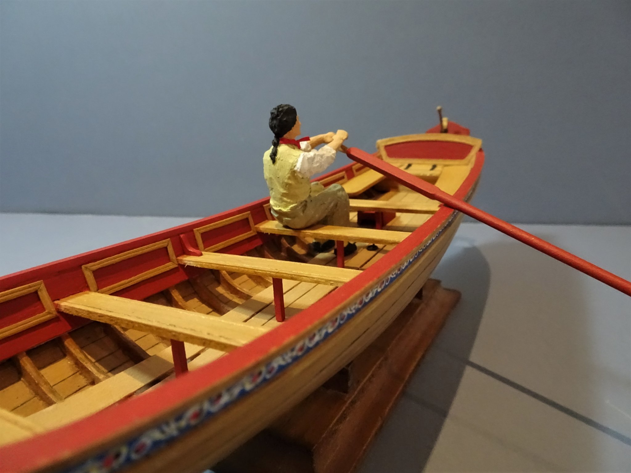
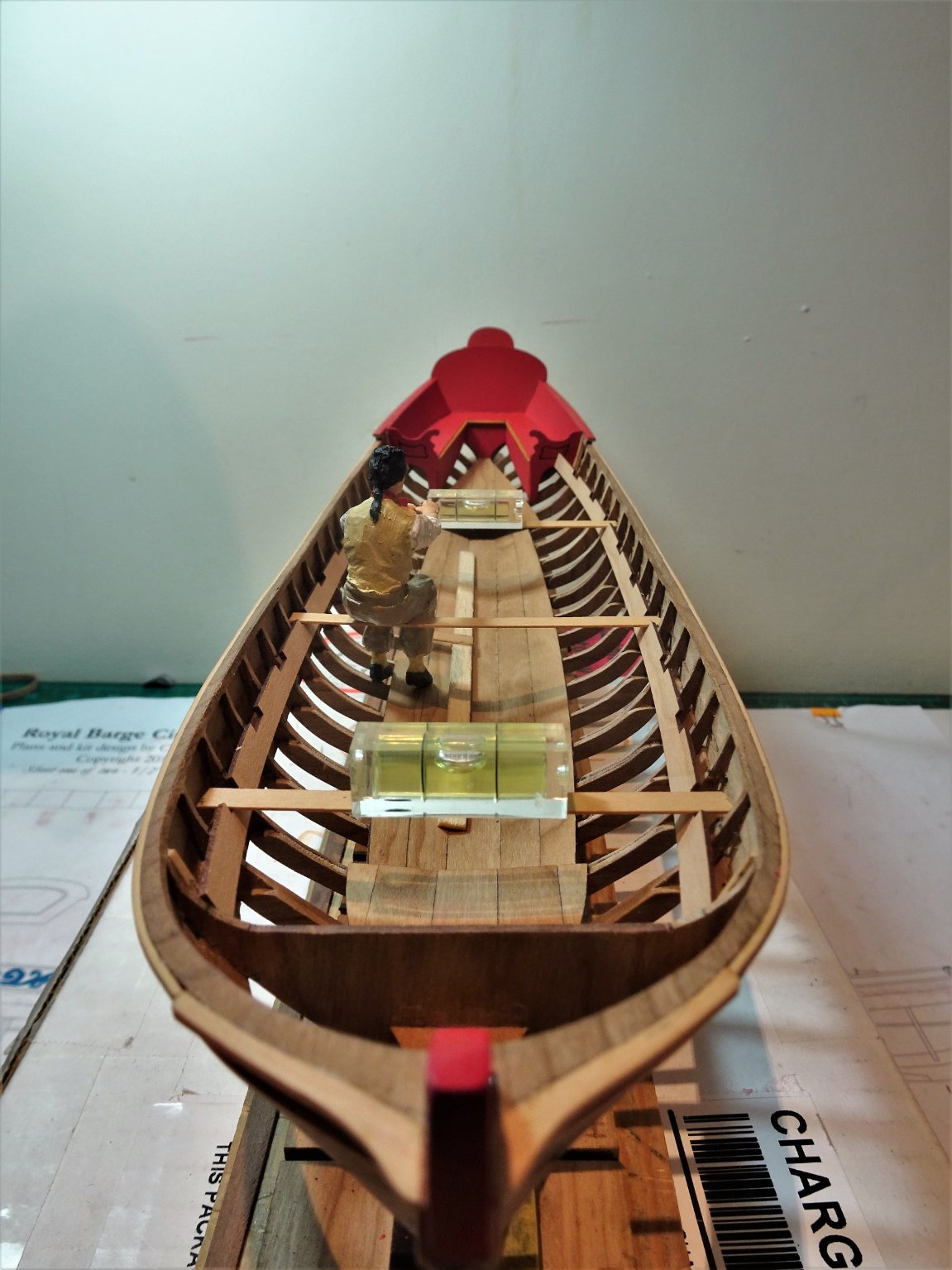
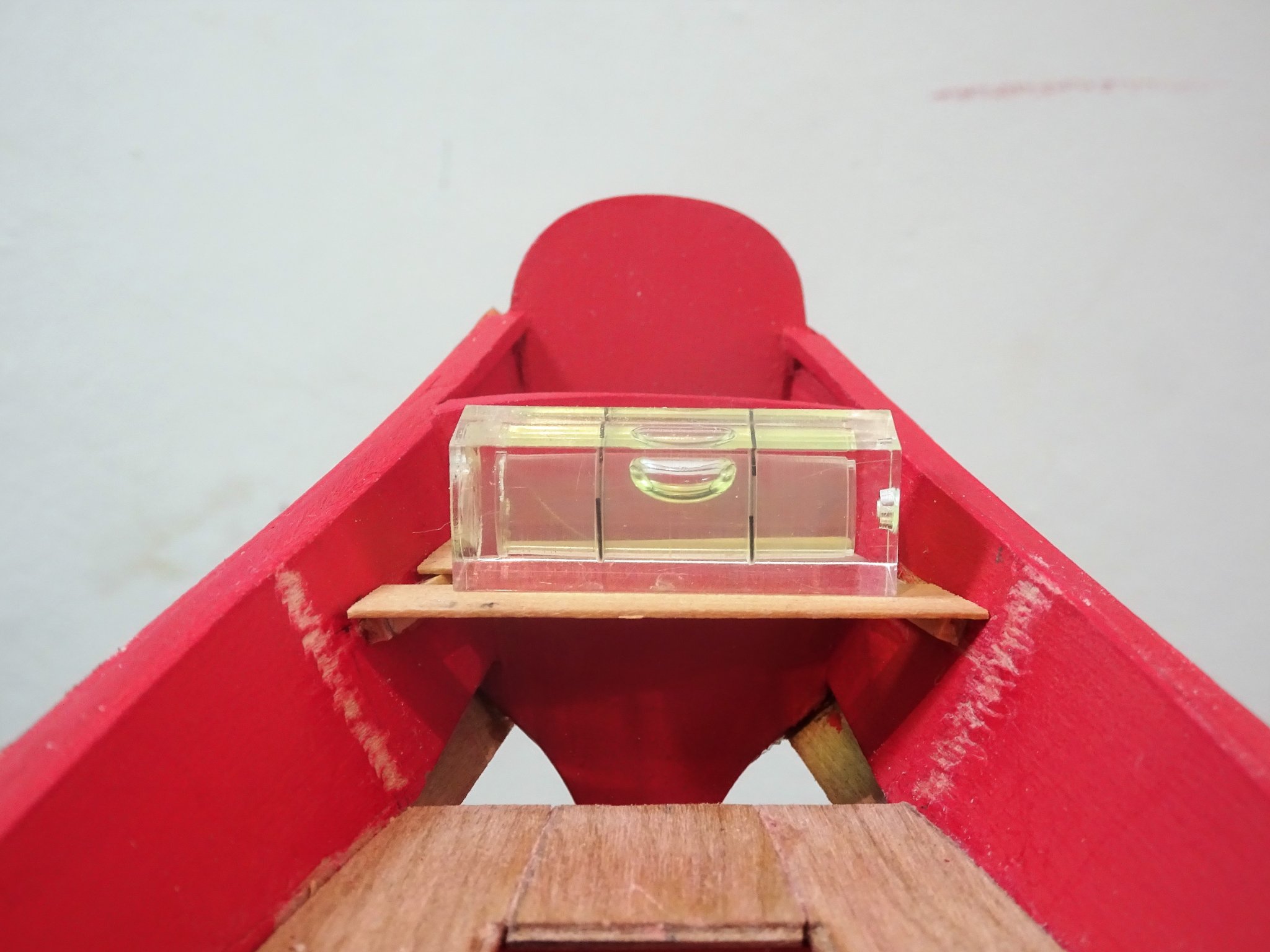
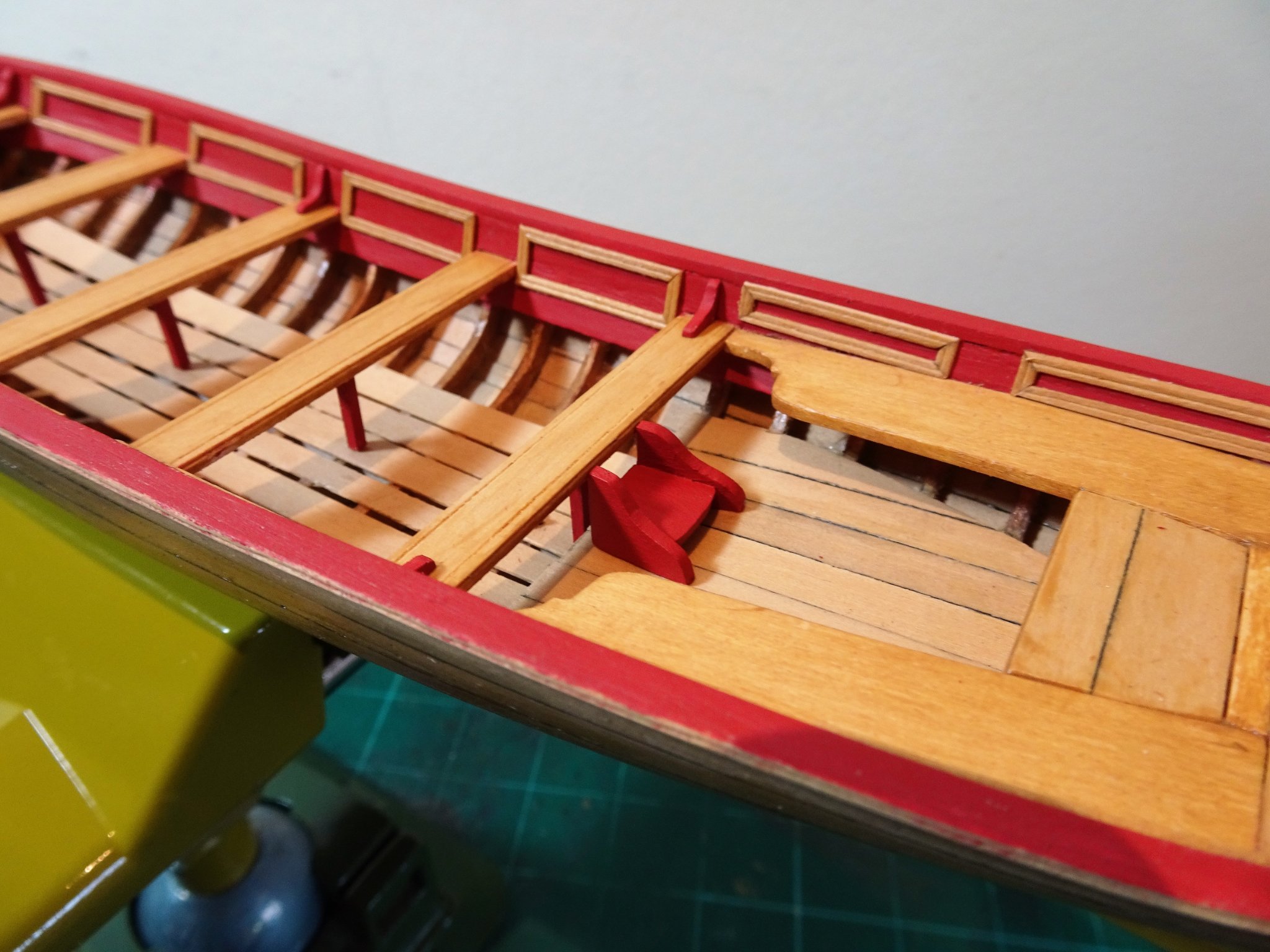
Post Twenty-four Stretchers These are bars running athwartships across the floor boarding for the oarsmen to brace their feet against to give purchase when rowing. They are secured by chocks cut into long timber strips that run along the inner sides of the boat above the decking. The question is how to approach the job, it seems quite tricky at first thought. The strips that hold the stretchers need to be even on both sides, remain vertical, but have both a convex curve on the horizontal plane, and a concave curve on the vertical plane, to follow the frames on which they sit. Chucks Model The plan in my kit (2018) does not reflect the required set-up, and the exact positions can be seen in the instruction photo’s as shown above. My approach. The two easily determined points are at either end of the strip. I glued the Port and Starboard strips at both ends to the frames in the correct positions and used temporary cross pieces (stretchers) to check the squareness before the glue fully set. At this point I have not glued the remainder of the strip length to the frames. 1692 The related temporary thwarts were put into place to check they ran in line with the stretchers. 1694 One side of the strip was then glued down using weights until the glue grabbed. Small wedges were used to make sure the strip didn’t move downwards towards the decking. 1697 I then glued the stretchers in place at the two end positions followed by the remaining contact points on the opposing strip, which was also then weighted. 1720(2) The remaining stretchers were then glued into place having checked that all the thwarts lined up with the stretchers, and that the stretchers were level across the deck. 1708(2) I had an issue with the laser cut thwarts in my kit which Chuck has quickly sorted out, but I used the now scrap (inverted) thwarts for test fitting purposes. 1711(2) The thwarts sit well along the risers and I am content with the result. 1712(2) Satisfying to see that the stretchers are not a bad fit for the test oarsman. 1713 1716(2) 1717(2) While I wait for the new thwarts to arrive there is plenty of other stuff to get on with, not the least the carving aspect to the decoration. B.E. 01/05/21
.thumb.JPG.ba470198795a00da07353099e3b8ffd1.JPG)
.thumb.JPG.2d84ef95f1f145a2ca5d47c3d54c3b55.JPG)
.thumb.JPG.a3aa0cbe7ba8e41041535de2f417e1ef.JPG)
.thumb.JPG.1c0f9463b43b70b06b6eacaf661334f7.JPG)
.thumb.JPG.f2cfddeac1702a7bd79ef3a5158672b6.JPG)
.thumb.JPG.7ac488e1bc3ec3ae63795569429a1304.JPG)
.jpg.3471ec24d4a27ef12ab11b324f45a666.jpg)
- 185 replies
-
- 14
-
-
- queen anne barge
- Syren Ship Model Company
- (and 1 more)
-
Hi Ian, I am in contact with a company called Modelu. Modelu – Finescale Figures (modelu3d.co.uk) This is the company that produced the figures I used on my fishing boat builds. B.E.
- 185 replies
-
- 1
-

-
- queen anne barge
- Syren Ship Model Company
- (and 1 more)
-
He first put in an appearance on my Pinnace build also at 1:24 scale 0922 His origins are a Dean's Marine 1.24 scale figure, but he underwent some serious surgery. Originally he was a Vietnam War period American soldier in Jungle gear. His arms were broken in two places, his uniform and jungle hat cut away and he was given some clothes from the slop chest. I was pleased that at a given 1:24 scale he fitted the boat spot on, as he seems to do on the Royal Barge. I am seriously tempted to crew the barge in the style of the Museum model, but it won’t be cheap having a crew of nine plus the Queen at 1:24 scale made. B.E.

- 185 replies
-
- 12
-
-
- queen anne barge
- Syren Ship Model Company
- (and 1 more)
-
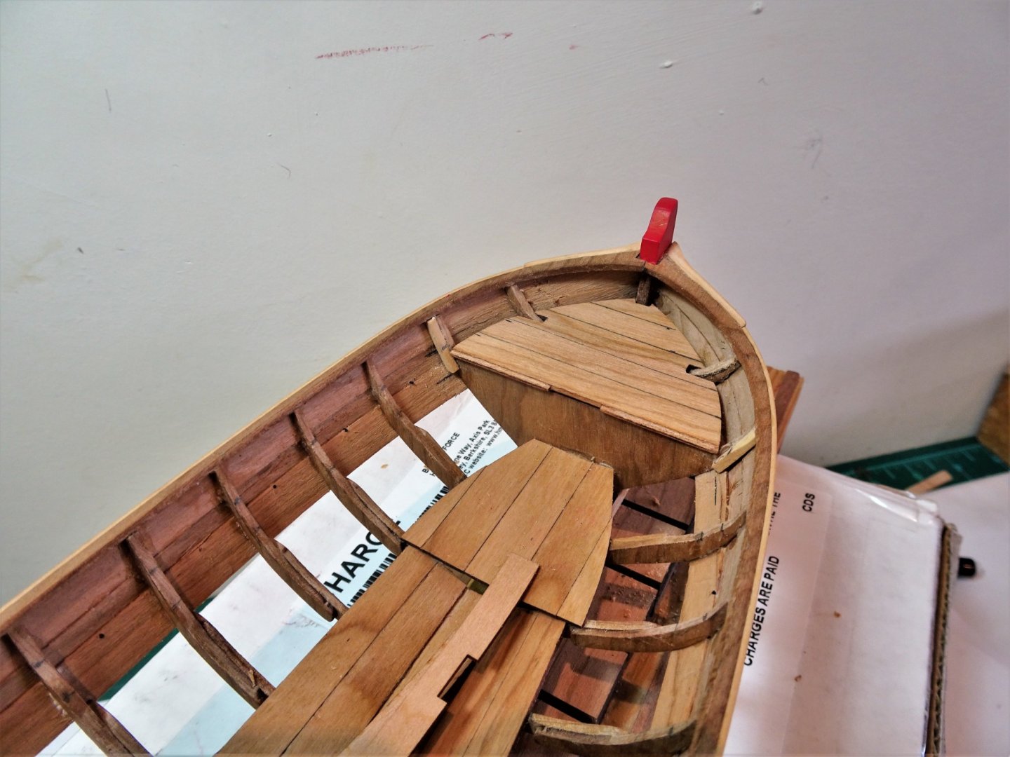
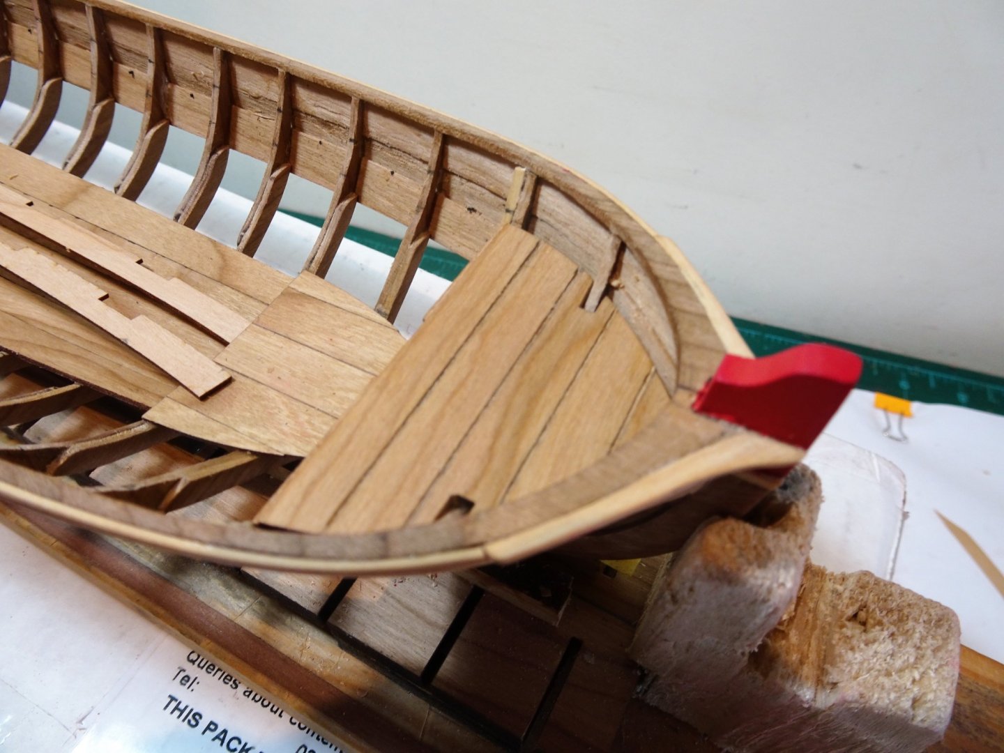
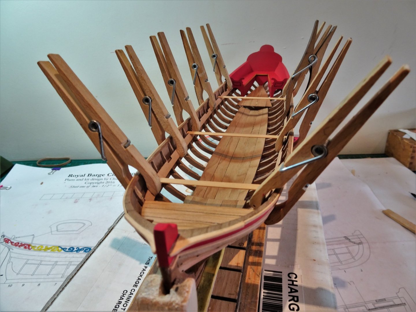
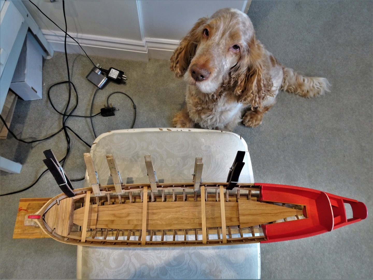
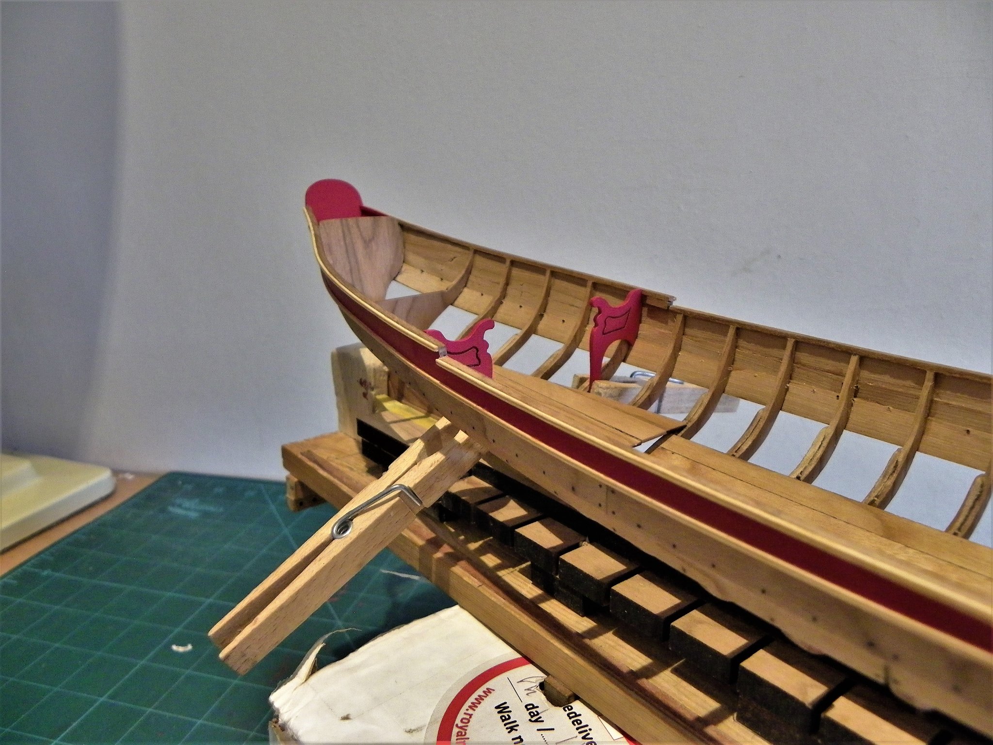
Post Twenty-three Rising to the occasion Well at least installing the risers, but before I begin I take one last critical look at the frames and apply a little more fairing. I also gave more attention the inner face of the lower planking that will be seen below the risers and cleaned that up before applying wop. The top level of the riser strips is taken from the plans and copied to the model using a strip ‘T’ square. The recesses for the thwarts are pre cut so it is important to not only ensure the risers are level across each side but that the corresponding thwart slots are square across the boat. Having marked the riser line I needed to get a feel for the fit. 1653 Temporary thwarts are set across the risers that are simply wedged into place against the top line marks. 1658(2) So far so good, and I bring my scale oarsman into use to check the relative height. 1654 He’s above average height for the early eighteenth century but even so doesn’t look out of scale to my eye. The next suggested task is to fix the risers, but before I went further I thought it a good idea to check the Fore-deck position as its relative height to the risers is important. After some faffing about I decided to fix the deck in place first, which will give a firm level to adjust the risers to. A small notch was cut out of the aft edge of the deck lip to allow the risers to pass and meet the bulkhead. 1667 To get the deck to sit flat on bulkhead ‘I’ I needed to pare down the frames a fair bit more. I note on the plan that the deck is shown as boarded, this is not reflected on the provided Cherry kit piece. 1669 Even tho’ the deck is intended for painting, I think it is worth scribing plank lines which should subtly show thro’ the paint. 1673 With the Fore deck in place a further dry fit of the risers. Can’t be too careful at this stage, out of square or level thwarts will ruin the look of a boat. 1677 With the riser of one side glued, temporary thwarts are again used to check that they sit parallel and square across the boat. The process is overseen by the critical eye of my boat yard assistant. 1688(2) Both risers glued into place and fitted with full size temporary thwarts. 1686(2) With some relief it seems that I don’t have to reposition a riser, and my eye detects nothing untoward. 1682(2) Satisfied with the result I can now move on to the stretchers. B.E. 29/04/21

.thumb.JPG.69a9690967d1d616fd5a0c012129103b.JPG)
.thumb.JPG.6dfed6e46529e9bd66695c4bc3b4cbc4.JPG)
.thumb.JPG.3399be6bc235c440b92980811173c090.JPG)
.thumb.JPG.7ed20eedd89b94e30a2b18aef6ce3ce5.JPG)
.thumb.JPG.c3326ed6ac3f866adadb39b3f6caf042.JPG)
- 185 replies
-
- 10
-
-
- queen anne barge
- Syren Ship Model Company
- (and 1 more)
-
A wonderful build Michael, full of interest, and you've created a great period look. She looks splendid in the display case, nice job. 👍👏 B.E.
-
Great progress Michael, I think your canopy looks wonderful, love the decoration and the impression given of a heavyweight fabric. B.E.
-
Thank you Glenn, I quite enjoy writing the logs, something to keep the grey cells occupied, provide me with an aide memoire of how I did something, and hopefully answer some of the questions others may be thinking in relation to the same build. Cheers, B.E.
- 185 replies
-
- 3
-
-
- queen anne barge
- Syren Ship Model Company
- (and 1 more)
-
Thanks Chuck, I see what you mean about the gold, it does look better in reality, but a simple thing to change. 👍
- 185 replies
-
- 1
-
-
- queen anne barge
- Syren Ship Model Company
- (and 1 more)
-
Post Twenty-two Completing the stern area Before I started multiple coats of thinned paint were applied to parts previously completed. The bench seats were next added. These took a fair bit of tweaking to get a good fit. 1613 I found it necessary to reduce the width of the bench tops from the back edge towards the aft end to allow adequate space for the smaller central piece, without reducing its size too much. The overall effect looks proportional, to my eye at least, and the fit was otherwise fairly good. It is not reflected on the model but I would imagine that parts of the bench tops were hinged to allow for storage. At this point I turned my attention to fitting the Coxswain’s benches. The height measurements were taken from the plan and transferred to the model. 1620 I decided to add bench supports in the form of 2mm square stock to aid the fitting of these tricky little pieces. 1624 Checking the level of the support rails. The space for the Cox’n between the stern sheets backrest and the Transom seems quite tight at 18”, but I suppose with an average height of 5’5” in 1700, it must have been adequate particularly if smaller men were chosen for the task much as in the case of modern racing shells. Still I digress… I left the final length of the Cox’s benches until I had got the fit of the back rest. I found this a tricky little beggar to fit. I started with a card template but I still scrapped the original Cherry piece due to over enthusiastic bevelling. I fared better with a replacement cut from a bulkhead centre, but this still entailed what seemed an endless trial and error process. 1627 I made up a simple jig using thin strip, to gauge the seat back angle. Once eventually happy with the fit, I returned to the Cox’s seats. 1628 Having fitted the supports I made a template covering the full width of the seat area. 1632 The seat back is glued into position against the template. 1642(2) The actual seats are then cut to size, bevelled, and slotted into place. I had toyed with the idea of leaving the bench tops natural but I didn’t find the dark Cherry shade against the red paint appealing. I think Box or perhaps Cedar would have given a more aesthetically pleasing effect. 00109 I left the Boxwood bench seats and thwarts natural on my Pinnace build (above) which I think does give a more pleasing contrast. 1641(2) A final check that the Cox’s seats match for level. 1648(2) 1647(2) I decided to detail the laser cut edges of the bench tops in gold, which I thought appropriate for a Royal Barge. 1649(2) The handling, gluing, and minor filling left its mark on the paintwork and inevitably further fine sanding and painting is required now the parts are all in place. I will attend to this before I move onto the risers. B.E. 26/04/21


.thumb.JPG.c247d1ed5c6184bf3c2a61402e7cd100.JPG)
.thumb.JPG.d952ff80fef359bbe698febd5c0955fd.JPG)
.thumb.JPG.6a29aa2ad9082d4363cc616e25ffd808.JPG)
.thumb.JPG.f76d0b13c00f9b9e4803e889ae8d87dc.JPG)
.thumb.JPG.b4935507537e3799f4a79bacafe781d2.JPG)

- 185 replies
-
- 10
-
-
- queen anne barge
- Syren Ship Model Company
- (and 1 more)
-
Thanks Guys for your interest and nice comments.👍 Post Twenty-one Internal stern fittings I am following Chuck’s suggested order of work for the internal fittings, starting with the stern area. Progress has slowed a little mainly due to a relaxing of covid restrictions, and a spell of fine weather tempting me out with the camera. This next part also bears some thinking about, even tho’ Chuck has laser cut all the parts, careful positioning and a little tweaking is still required, and I wanted to take my time with this important area of the build. 0172 The bench armrest were fitted first followed by the stern sheets internal boarding. 0173 For these I made card templates to tweak the fitting requirements before I committed to the Cherry versions. 0175 These were trimmed to fit and heat treated whilst clamped in place. 0183 I also made card templates for the bench seat supports before fitting. The ‘T’ square is used to mark the frame positions for the supports, taken from the plan, and to check the vertical line. A spacer is taped to Frame 10 to position the aft support piece. 0186 The pinky red colour reproduction on these photos is not realistic. On the model the Vallejo flat red is true. Once the glue has set, this area will be painted before moving on. B.E. 21/04/21
- 185 replies
-
- 13
-
-
- queen anne barge
- Syren Ship Model Company
- (and 1 more)
-
The 'B' reference indicates different types of blocks. Have a look on page 107, you will see different types of blocks annotated H7/1, H7/2 etc; These references relate to different types of block as identified on p 106. Look at Block H7/6 there is a small notation 'B9' which is described as Common single and double blocks A very convoluted way of doing things in my opinion. 'C' - cleats 'D' = Deadeyes B.E.
-
A fine looking model Erik, you must be feeling well satisfied, and she looks very elegant in her display location. Well done B.E.
- 222 replies
-
- 2
-
-
- First Build
- Lady Isabella
- (and 2 more)
-
Nice progress Tim, great looking gammoning, and wooldings, and nicely shaped False rails. 👍 B.E.
-
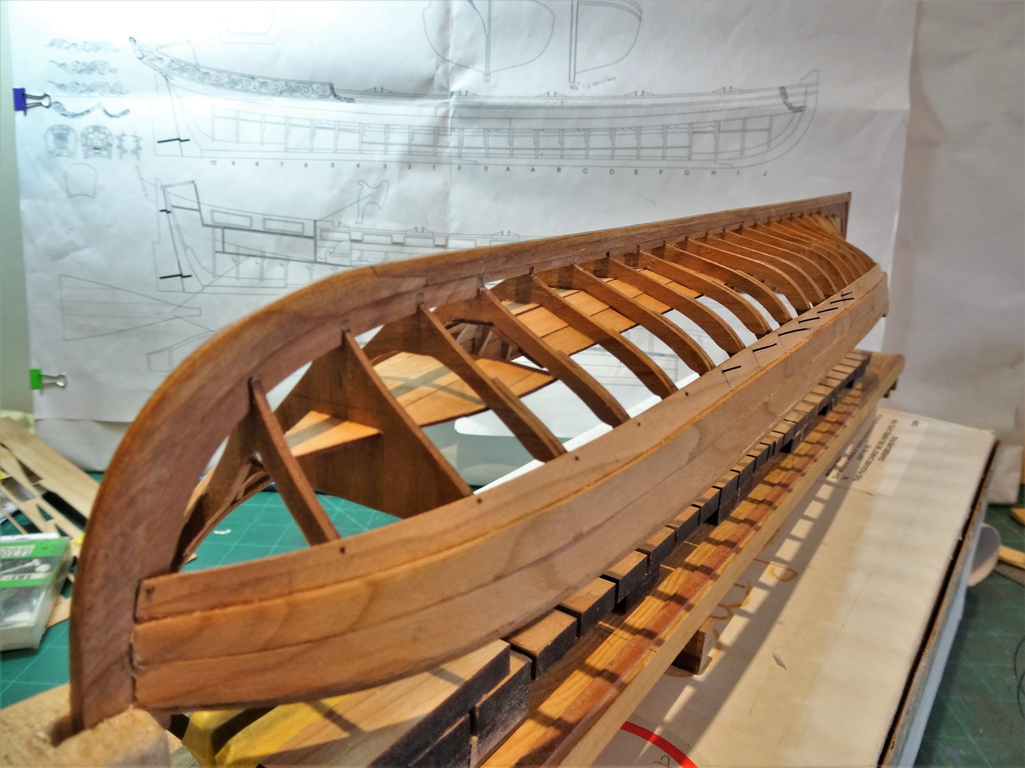
Post Twenty Completing the First section This involves cleaning up the hull, fixing blemishes, and re-coating the topsides. The moulding rail has been extended onto the Bow stem, and paint added. A Further coat of wipe-on-poly was applied to the unpainted areas. I will leave the painting of the capping rails until I have fixed the internal panels. Progress photos to complete this stage. 0114(2) 0115(2) 0116(2) 0118(2) 0124(2) 0127(2) 0153(2) Moving onto the internal fittings. B.E. 16/04/21
.thumb.JPG.c2c8b5e9f7263dc1962f4e561015007e.JPG)
.thumb.JPG.00c3e356fbe18551cbbd3c9b284cd9ae.JPG)
.thumb.JPG.7295fc10380ec69dcd3693cae46babf6.JPG)
.thumb.JPG.a10a91bbe7741dd3d080e4e50187f6ef.JPG)
.thumb.JPG.b764b8cfc2cc3800d84f9a999cbc4dc0.JPG)
.thumb.JPG.8c212c82cb730cf9d947c8ff0a1e91b6.JPG)
.thumb.JPG.aeb1c942998a87bec92296eec2482cd7.JPG)
- 185 replies
-
- 18
-
-
- queen anne barge
- Syren Ship Model Company
- (and 1 more)
-
You're making excellent progress Jean-Paul, Gunport linings look good, and very clean work overall. 👍 B.E.
-
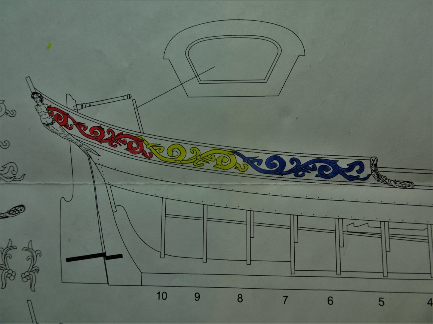
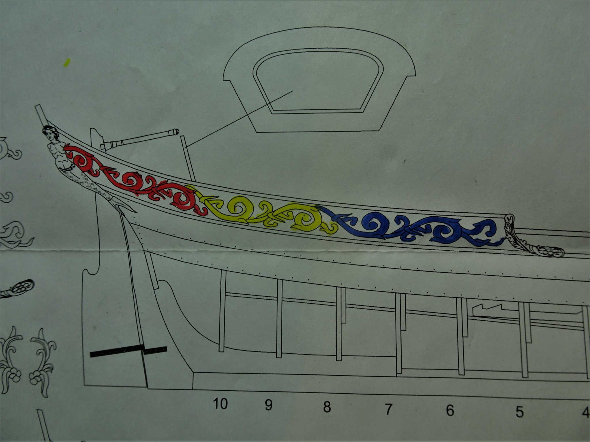
Post Nineteen Lower Moulding Rails The stern Frieze patterns that run from the Flying Transom to the break of the stern sheets govern the position of the lower rail which sits just below the carved decoration. 1588 I used separate colours on the plan to better identify the individual carving pieces. Between the upper rail and the lower rail top there is a space of 4mm running from the bow to around Frame O where it starts to widen by degrees. I used a 4mm wide Pearwood plank to mark the level of the lower moulding to this point, and applied Tamiya tape to secure the line. 1589(2) I cut out the frieze patterns from the plan and Blu tacked them in position to determine the level of the rail at the stern. 1591(2) The required space was thus established and marked with Tamiya tape placed to run with a natural curve to meet the previously placed tape. The main objective is to get a smooth transition and avoid any hint of an awkward angle in the run of the moulding. I have decided at this point to get some paint on the topsides before I apply the lower moulding. 0056(2) This will speed up the process and will provide a good line to fit the moulding to. For the purpose I am using Vallejo Flat Red. With five thinned down coats applied it is time to fit the lower moulding strip. Further coats will be added post fitting. The Boxwood strip used for the moulding is not long enough to cover the full hull length and requires a join. 0066(2) Fortunately, there is a sculptured ornamental decoration that runs downward at the break of the sternsheets and covers this point. I am using ca to fix the rail, but careful as I was tiny amounts of excess ca squeezed above the moulding which will mar the paintwork. 091(2) This is why I haven’t sought to complete the paintwork before fixing the rail. 094(2) 089(2) 086(2) 0108(2) Testing the fit of the carved decoration blanks, I did have to tweak the aft rail sections to get a close fit to the carvings, but fortunately they popped off easily enough with the point of a scalpel blade. Before I move on to the next phase there’s a fair amount of cleaning and further painting to do. B.E. 11/04/21
.thumb.JPG.da2fcb6ed8f30b3c6d03fd46473efafe.JPG)
.thumb.JPG.f26a0418a8a6c6d9e01cc1aca8739bed.JPG)
.thumb.JPG.6c8f317d2b5750a494fff3cbb1545d31.JPG)
.thumb.JPG.a8cc4b01d7399f744e8d5ebcd58e8578.JPG)
.thumb.JPG.c00bf303a6ec740243d92e0be30b3201.JPG)
.thumb.JPG.2e375f6b26658e13d59d264b9d418bdf.JPG)
.thumb.JPG.98087ee4302d7f4750d72b8996d2f5a7.JPG)
.thumb.JPG.a6fe40176fcf7791c2d55dff26f2921e.JPG)
.thumb.JPG.3870cc59623d513961b075f812e2720c.JPG)
- 185 replies
-
- 15
-
-
- queen anne barge
- Syren Ship Model Company
- (and 1 more)
-
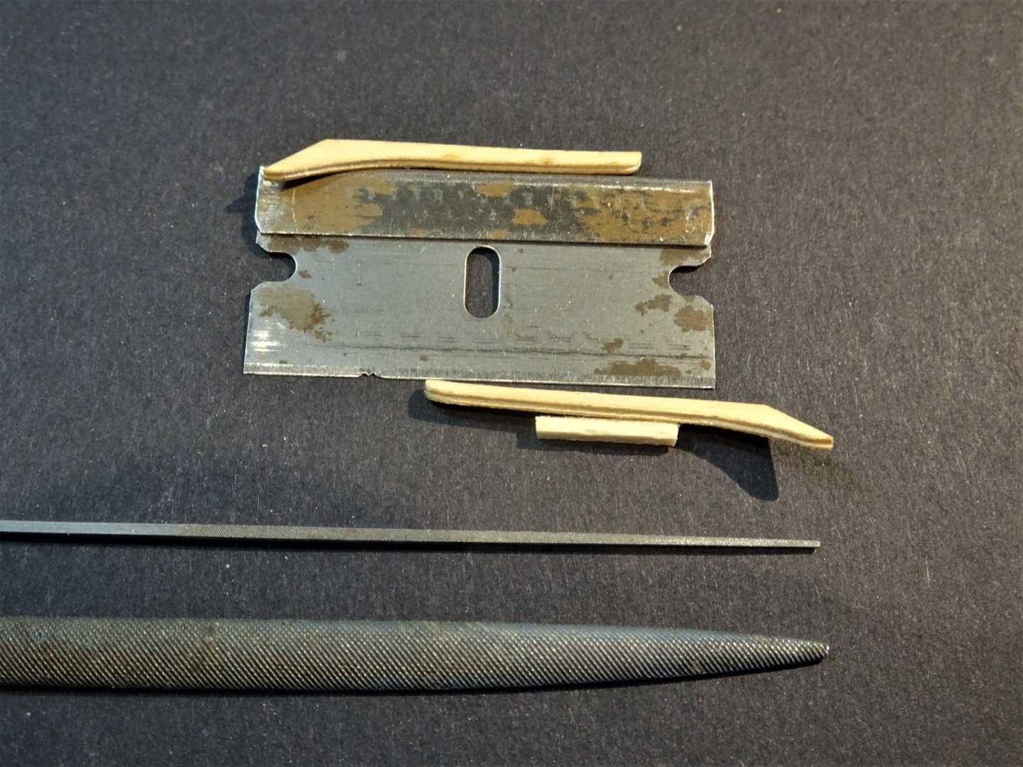
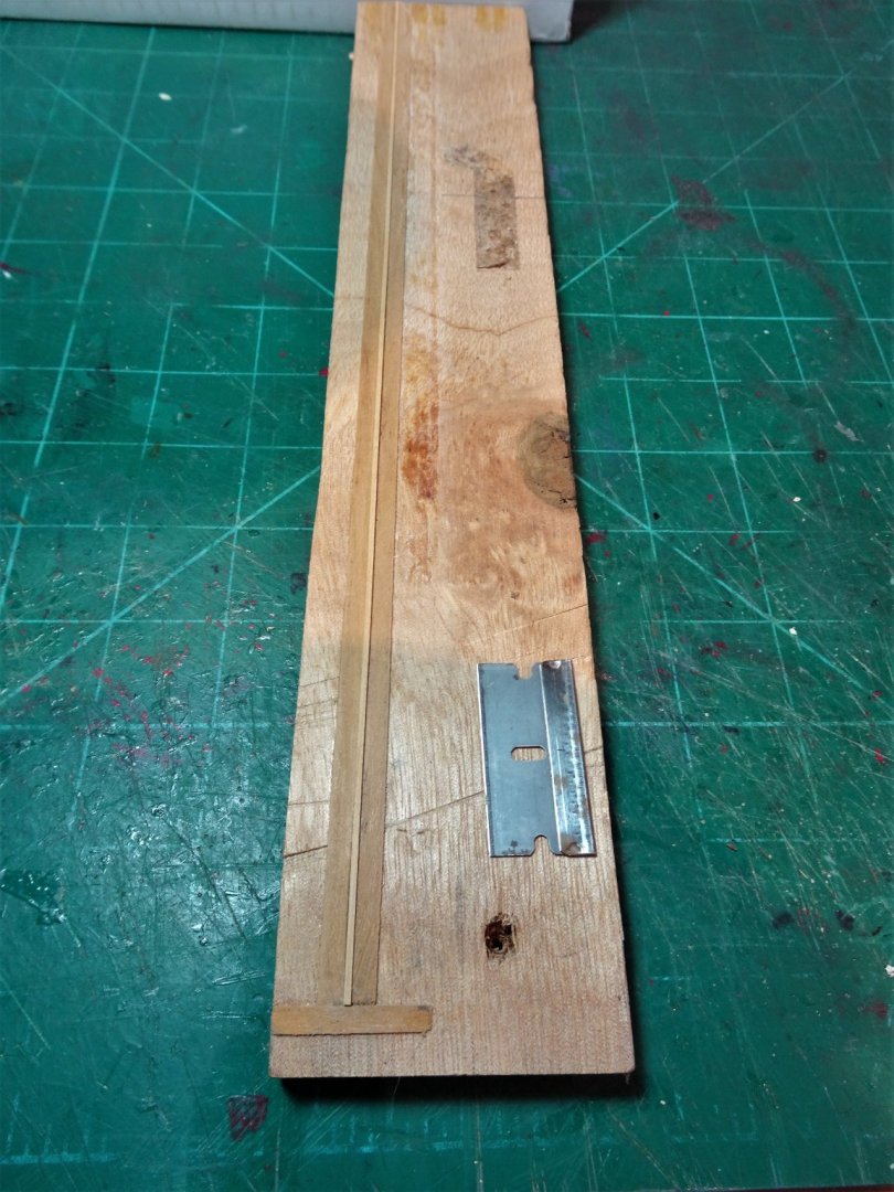
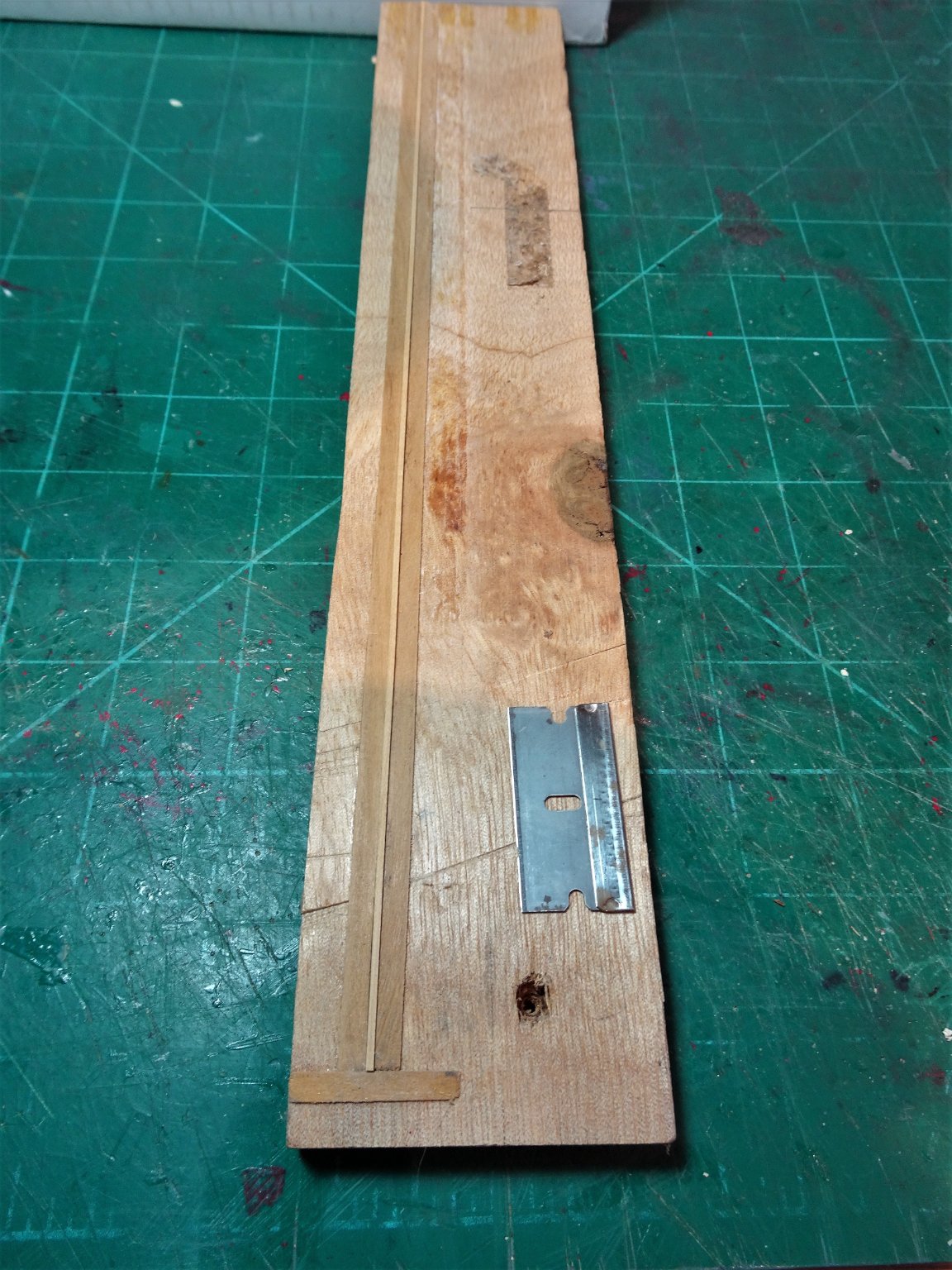
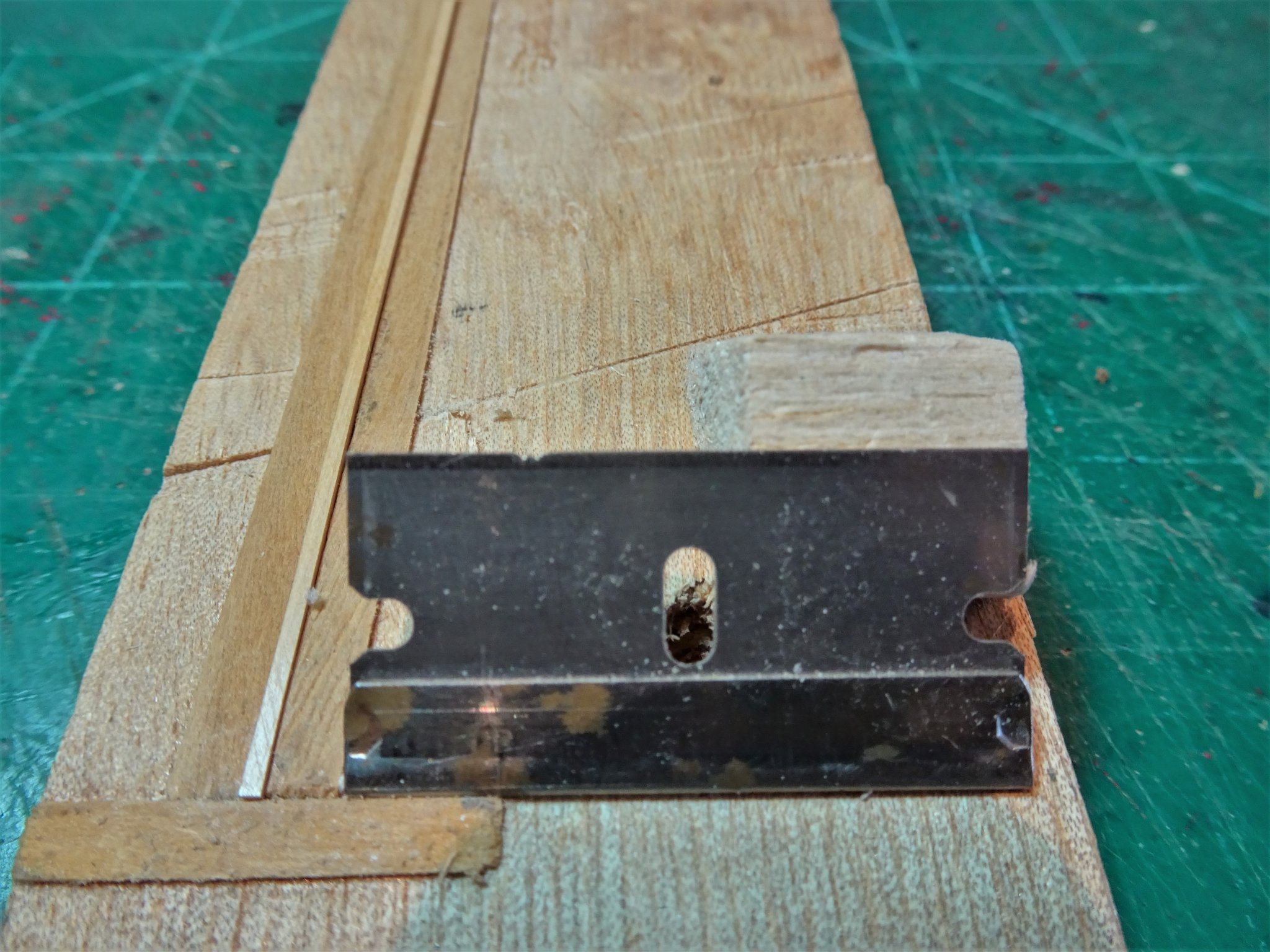
Post Eighteen Ears and Cap rail mouldings. These are provided in the form of pre-shaped Boxwood pieces for the ears and Boxwood strip for the mouldings. These items require a shaped profile to be scribed into the face. I start with the ears; the profile must be simple given that the edged surface is a mere 1.2mm wide. The means is a single edged razor blade, and the way is to cut the profile shape using the edge of a mini file. This is a method I have used on all my models requiring a fancy edge to rails. 1550 Several passes along the ears, and the centre groove is cleaned using the point of a micro file. The same procedure is used to create the profile in the Boxwood strips six of which I think will be required, barring mishaps. The big danger with the fragile Boxwood strips is running off-line as the profile blade is drawn down its length. These strips are 1.20mm wide and 0.90mm thick, and 325mm in length. 1554 I use a simple guide jig to hold the strips to prevent lateral movement. Well, that’s the plan. 1561 The very tiny profile shape can be seen here cut into the blade. 1552(2) The ‘ears’ go on first, needed a tiny bit of fettlin’ to get them to fit reasonably tight against the cap and stem. 1578(2) I used pva to glue the ears on. 1576(2) With the glue set, a little re-shaping was necessary, which resulted in re-scribing of the profile pattern where it meets the stem. 1584 I used ca to fix the top moulding along the cap rail, and heat bent the forward end to de-stress the curve around the bow section. 1585 For the stern section I found it better start at the Flying transom and move forward, as the moulding finishes at the forward edge of the FT and is angled to suit. 1575(2) I now need to establish the position of the lower moulding to allow for the frieze work and decide at what point I will paint the area between. B.E. 09/04/21
.thumb.JPG.ef8ddef3b15c0ab3207beccfb1a2fc7e.JPG)
.thumb.JPG.c2f5010691f04c2bf69e80c2f358aa89.JPG)
.thumb.JPG.407424df90e055ac011760ecd6816437.JPG)
.thumb.JPG.9be31c15d7f47605822fd987bb87c704.JPG)
- 185 replies
-
- 15
-
-
- queen anne barge
- Syren Ship Model Company
- (and 1 more)
-
Thank you Michael and Bob, @ Michael - Yes those are the untrimmed filaments, works quite well in this situation with a delicate hull and not much to drive into. Easily trimmed with a scalpel blade, and to sand flush. @ Bob - sounds good to me Bob, and your trip sounds wonderful, have a great time, and stay safe. 👍 B.E.
- 185 replies
-
- 1
-
-
- queen anne barge
- Syren Ship Model Company
- (and 1 more)
-
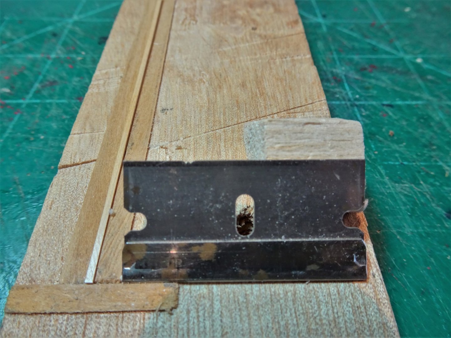
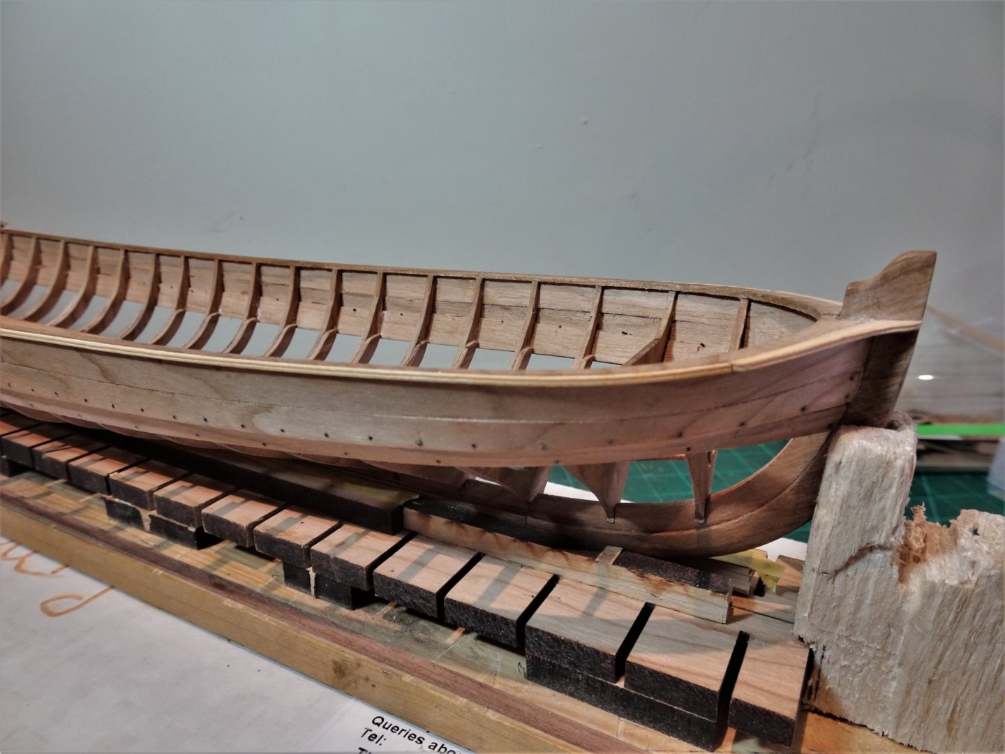
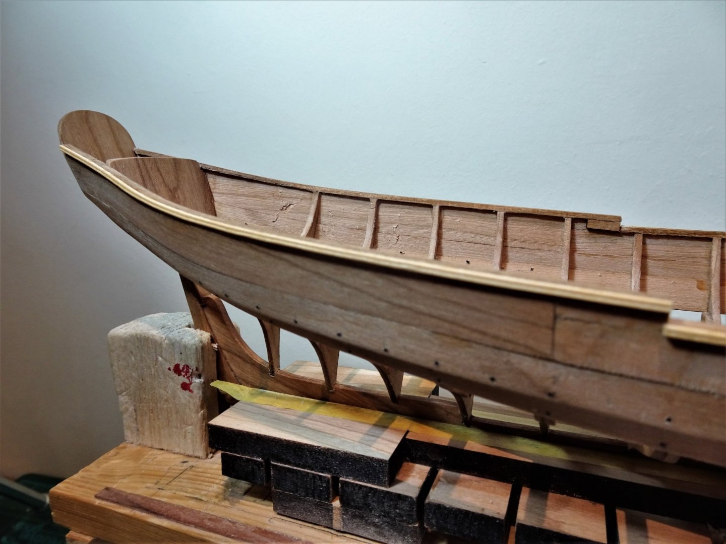
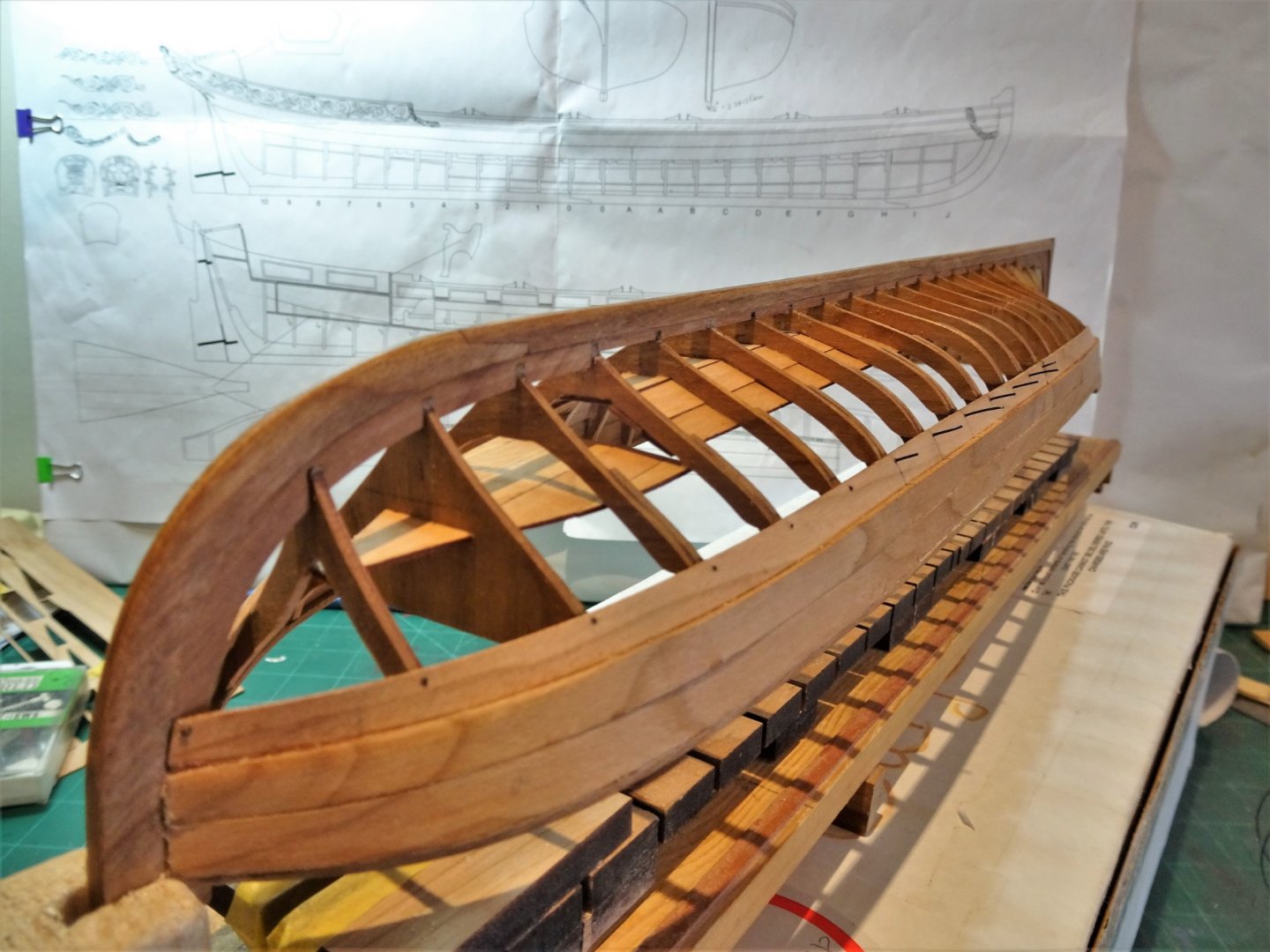
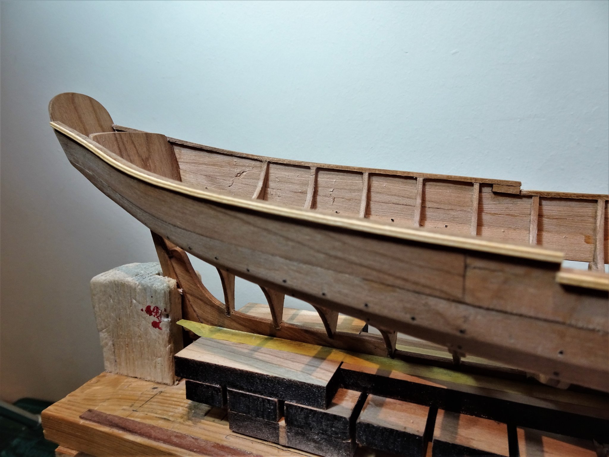
Post Seventeen Adding the nails Following on from my last post I have applied wipe-on to the decking and the framing below the hull planking, and a further coat to the keel pieces. I now need to consider the nailing. Having applied some several thousand copper nails to the clinker hull of my Alert build, this seems like light relief. 20lb black Filament is supplied and a#74 drill bit is recommended for the purpose. Some 1650 mm of line is provided which is sufficient for 330 5mm lengths, more than enough to fulfil Chuck’s suggested arrangement. I’m not familiar with either filament or #sized drills, but converted to metric a #74 drill = 0.5334 mm ø drill #75 drill = 0.5334 mm ø drill The filament has a 0.5mm diameter, and I used a corresponding drill to suit. 0.5mm ø at scale equates to 0.47” which seems somewhat overscale, and less than half of this is probably more appropriate. However, I appreciate that the whole nailing set-up is purely artistic license, but I rather like the effect. For the lower plank I have restricted the nails to only where the plank crosses a frame, it seemed pointless to insert a nail into a plank without anything to connect it to. In reality a clinker-built boat would be planked from the keel up. 1520 For this operation I inverted the boat for ease of working. 1522 I eyed the position of the nails and used a simple jig to fix the drill point at 1mm from the edge. For the upper plank nailing I followed the kit scheme, again sighting and marking the position, and using the jig for the drilling. 1532(2) This time I had the boat the correct way up for marking and fitting and inverted for drilling. 1542(2) 1543(2) I have decided not to apply any more wop to the planking until I have fixed the moulding rails which is the next stage of the operation. B.E. 07/04/21
.thumb.JPG.7279fcc687c537a66c067e4ab18d3211.JPG)
.thumb.JPG.185c13667d2dcb0d33f66bac5e383677.JPG)
.thumb.JPG.ac4a23cfd3f8ffb05a7b8af24a570f83.JPG)
- 185 replies
-
- 13
-
-
- queen anne barge
- Syren Ship Model Company
- (and 1 more)
-
Always an exception to prove a rule, we are talking generalities here. B.E.
-
The one I heard is that you can put a boat on a ship, but not a ship on a boat. B.E.
-
Boats are very welcome, at least my last several builds haven't been thrown off the site, all much smaller than ships.😃 B.E.
-
This thread makes me smile when I consider how contemporary models and even more recent iconic models such as Longridge’s Victory are treated. Even the NMM no longer considers most ship models are worthy of displaying and has shipped them off to storage at Chatham. The last time I saw Longridge’s Victory it was in a poor condition, and that too is no longer on display at The Science Museum. Sadly, the broad sway of the public have no interest in ship models, including most of your relatives. How long the models we build last is of little consequence in the overall scheme of things, build them to enjoy in you own lifetime. B.E.
-
Thank you Jean-Paul, I regularly check out your excellent build as I proceed. B.E.
- 185 replies
-
- 1
-
-
- queen anne barge
- Syren Ship Model Company
- (and 1 more)


.JPG.983d4b1e93bc0191bee9b15fb6cafe50.JPG)
.JPG.5d3405ed3b0de52627b51cdd2ac82dc5.JPG)
.JPG.ac5a1cf65152ea3794fd282dfb11e31c.JPG)

.JPG.b78053f68d2c03de63472fc3c034ce3d.JPG)
.JPG.ba3bbd8d2b109895e6bd59da8cd77365.JPG)
.JPG.d80b136f5314d5249f1f5ffe97df75bf.JPG)
.JPG.f3ba681c1f1076f9a23c787a4d7eaf3c.JPG)
.JPG.897f001e395b07ccdb579c213387f15b.JPG)


.JPG.33a286cda723721de77fd1ef78910a60.JPG)
.JPG.0156d54aad70024c134e0b43b9b1ab26.JPG)
.JPG.21948b341295af6c263e79378250a3e7.JPG)


.JPG.b8b4cb380b216996b2365f7193620970.JPG)
.JPG.809fae33fd04ab3d778a898158e01b10.JPG)
.JPG.6eb9c5bd841dbc1b22127b8fc515d9bb.JPG)
.JPG.db72ef4b757775b181e9db6f322ac6c1.JPG)
.JPG.1eb8140fa7a39494d0063d31d9ef639d.JPG)


.JPG.fbdd6706398cd9699df22582c3a32b7d.JPG)
.JPG.8b8719484646df02fe2c596ce96d81dd.JPG)
.JPG.3d82a610328292b39b65acb2cb867cbf.JPG)
.JPG.d9e65d845a5bef7c5a762409b7b3b758.JPG)
.JPG.03c68da7e4a018196b6eb6e498982bfb.JPG)
.JPG.aad156569c53a16f3a3f933810b28b21.JPG)
.JPG.f91cc57e332d8c6d8f6c2d3e2ab1f2e1.JPG)
.JPG.d1e4f7c1550f2f16017377fef2a96eda.JPG)
.JPG.494a1c87cdc8d169f8460076c365288a.JPG)
.JPG.0ec0e5aa413e6ab45c97dad85081732c.JPG)
.JPG.c1d8ab5c31090b455a02fff313c3fb42.JPG)
.JPG.033fa023a042b06cfbdf020344219d7f.JPG)
.JPG.df0712b135c54cd112969727ef3f99e2.JPG)
.JPG.eaa4ee25430049112b59ab33d870bca8.JPG)
.JPG.3509cbe7d6e25f056b5fd6384cdf965c.JPG)
.JPG.bd82f2c07036dc124842ad176f5dc86c.JPG)

.JPG.35567d7cfa7675ca846a8d49df7428c5.JPG)
.JPG.086890f9e43e33cc290d2b81e7b60fb0.JPG)
.JPG.4152c8737fc9f6ad837b54a31ad9309a.JPG)
.JPG.4b9f892608144aea12ec4e2e51b444fd.JPG)


.JPG.8c2e56891bd90ca6faa4d51b4cd1a8e3.JPG)
.JPG.c7d4c256a7f61a1bcbb7638b30704f01.JPG)
.JPG.8c8f6baefda63d90cadd911eb6593914.JPG)
