.JPG.ca33079f5815b861e67b9c2cccd37982.JPG)

Blue Ensign
-
Posts
4,572 -
Joined
-
Last visited
Content Type
Profiles
Forums
Gallery
Events
Everything posted by Blue Ensign
-
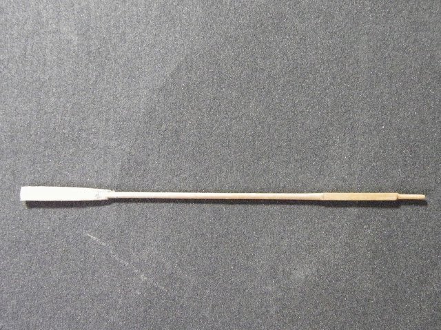
 Nice job on the oars Derek, can't beat the Boxwood look on small boats and oars. The whole model is looking splendid. 👍 B.E.
- 725 replies
-
- 1
-

-
- vanguard models
- speedy
- (and 1 more)
-
Nice set up on the gun rigging Richard, I bet you're pleased that repetitive and fiddly exercise has been completed. B.E.
-
On the NMM version the helmsman still sits behind the sternsheets, perhaps lines were a less intrusive option. On the kit version the tiller is quite short, but the space for the helmsman is pretty small. Thanks Ian, that's what I would plan to do, the red painted internal planking and capping rail would join the two sections together. B.E.
- 185 replies
-
- 1
-
-
- queen anne barge
- Syren Ship Model Company
- (and 1 more)
-
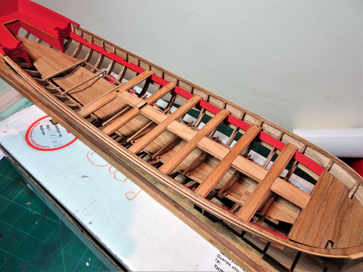
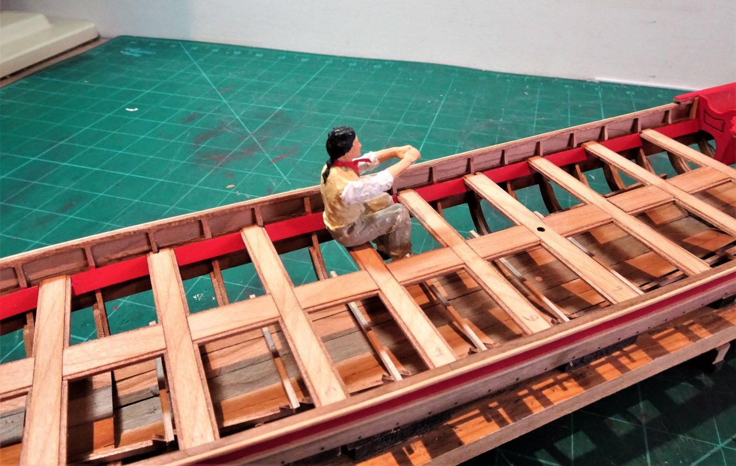
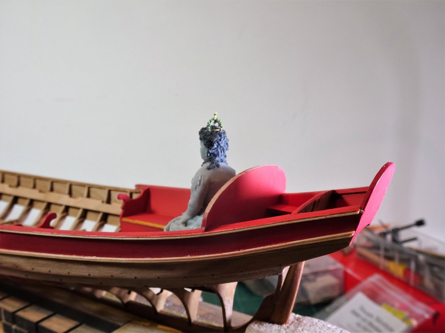
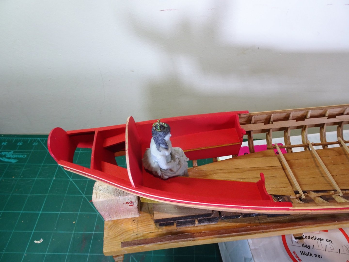
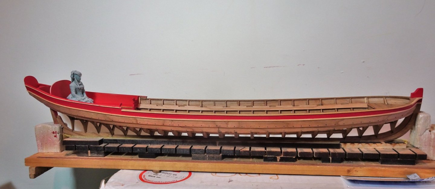
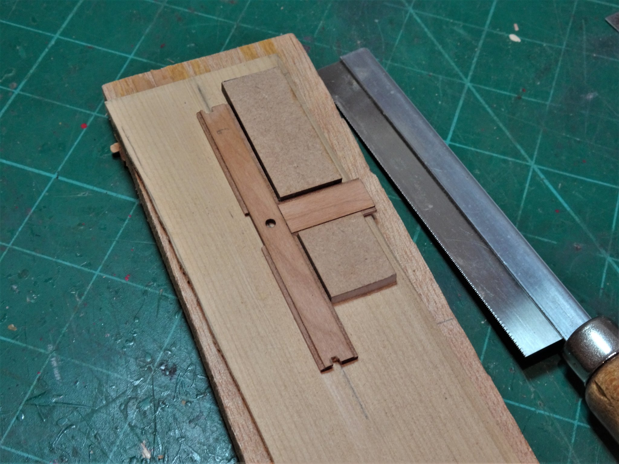
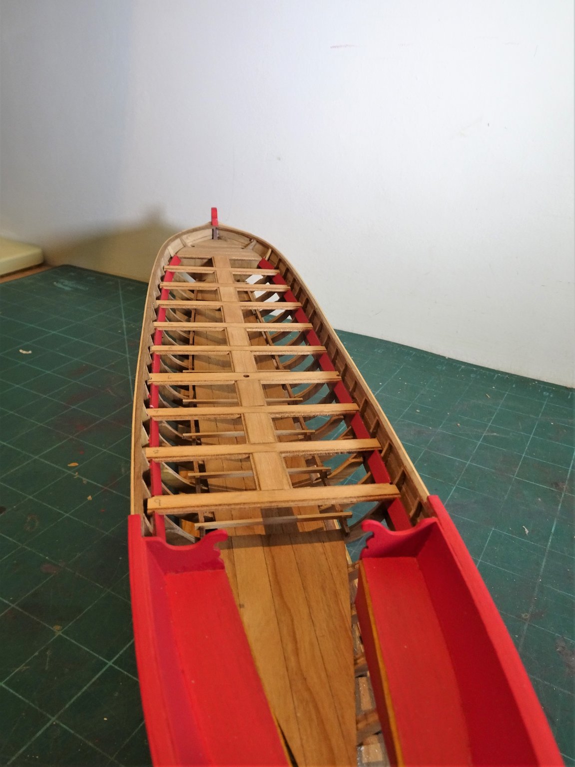
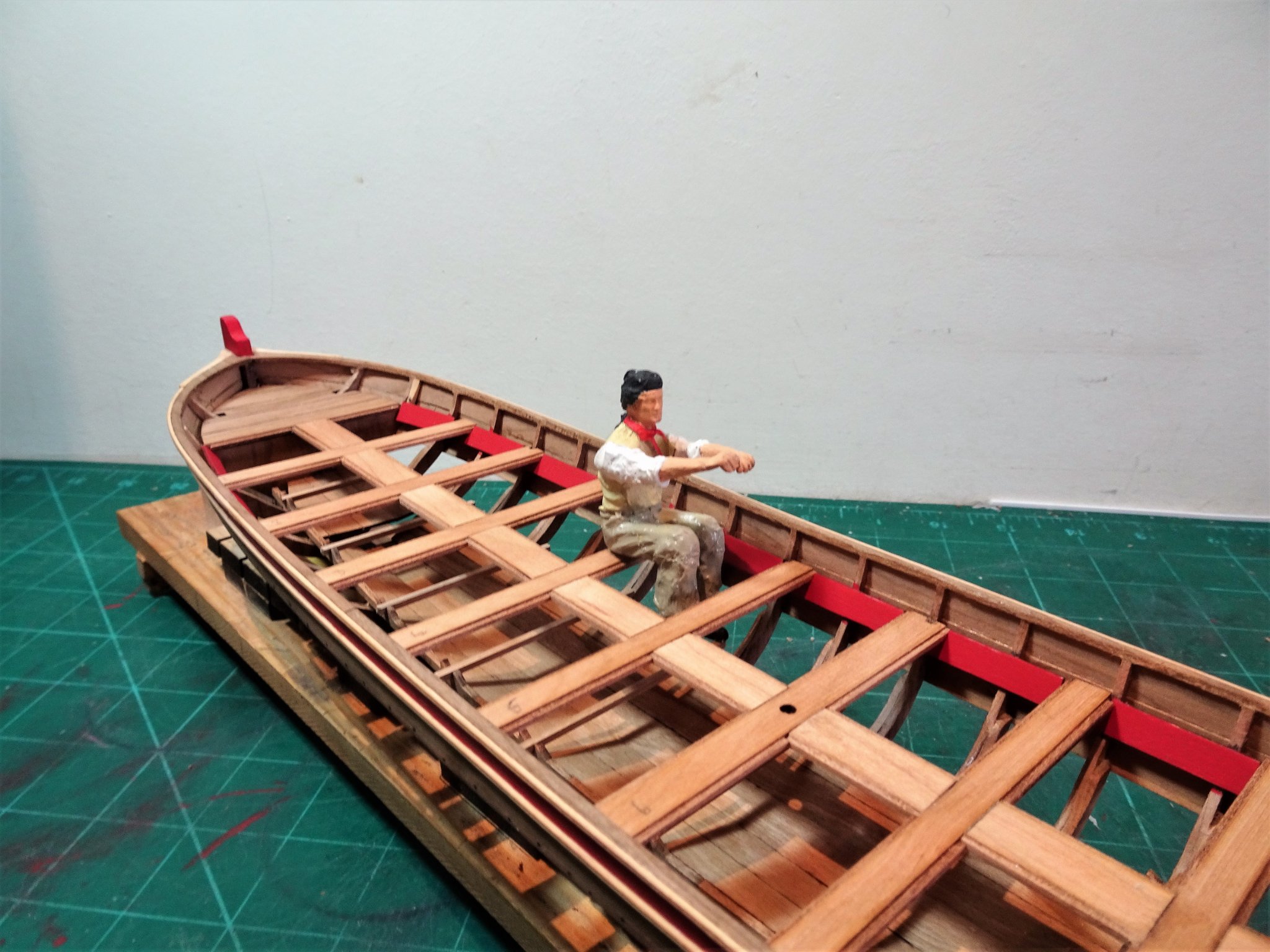
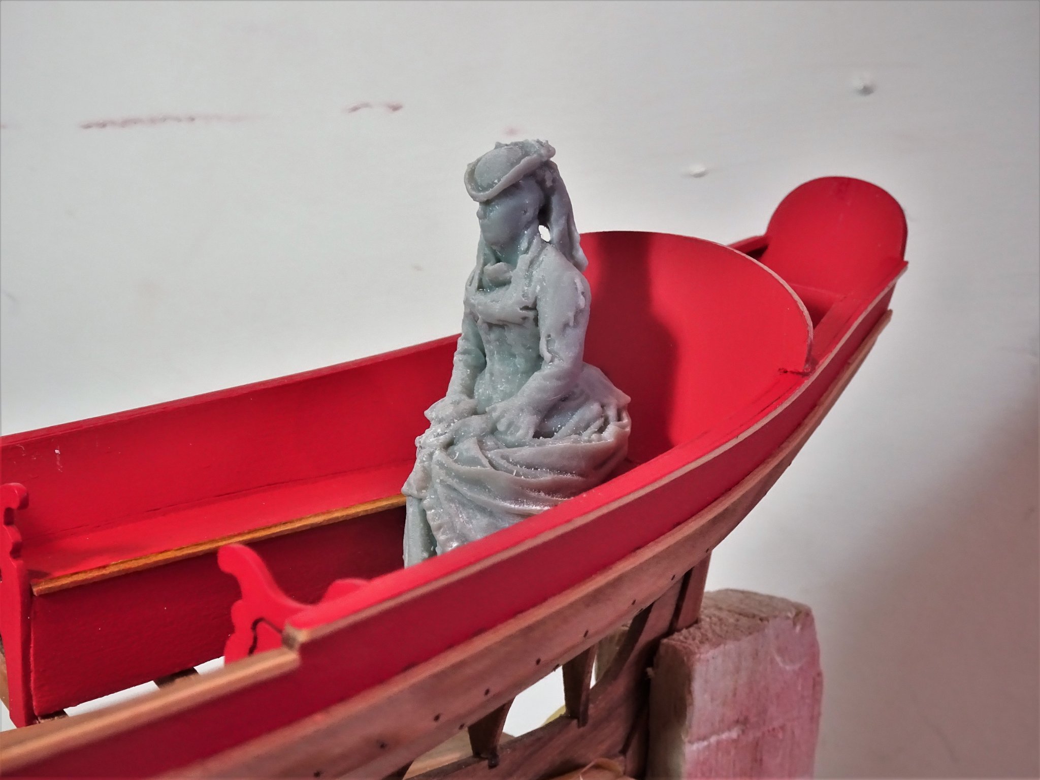
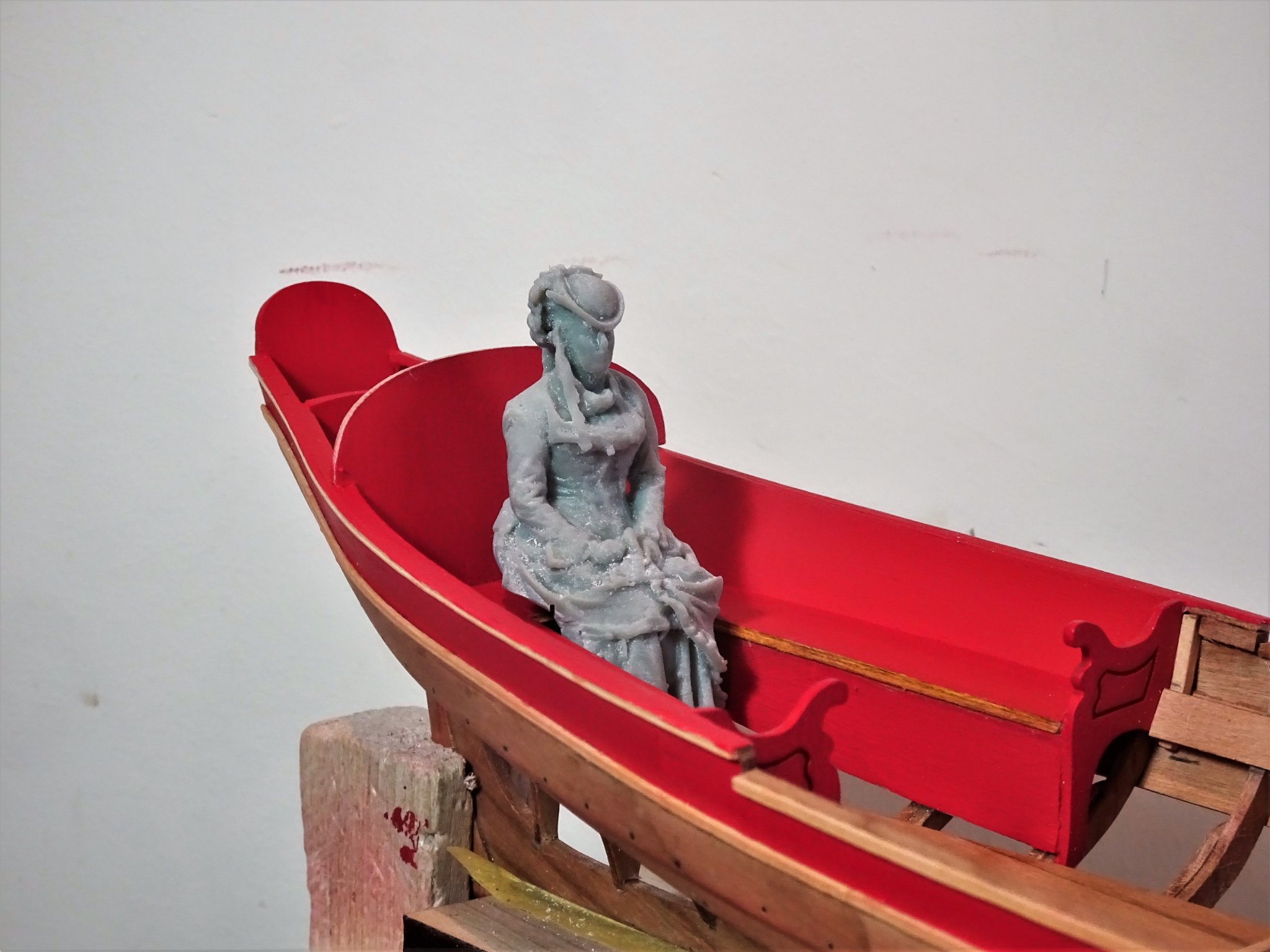
Post thirty-one Progressing the seating This involves placing sections that fit between the thwarts centrally down the boat. The main objective is to get a tight clean fit up against and either side of the thwarts. I start by gluing a section into thwart one, the forward end fitting into the Fore deck edge. The sections will require cutting of one edge to fit the space, the length is marked and cut sufficient to leave a final sanding trim. 1880 To this end I made a simple jig to hold the thwart and centre section for sanding. I took this process very slowly with constant test fits. 1877 I moved progressively down the boat until each thwart had a centre section that fitted into the thwart forward of it. My decision to notch the thwarts around the frames proved the right one. On three of the thwarts, I did need to tweak the fit to get the centres in line; had I initially trimmed them to sit only on the risers, one side may have been left without support. Once I had completed the whole thing I reviewed and replaced three centre sections where I thought the joint insufficiently tight. Fortunately, Chuck includes a few spares no doubt for this purpose. 1882(2) One of my concerns is that viewed from the side the centre line planks run in a subtle sheer line from bow to stern without any hint of an angle. 1885(2) Being unglued at this stage the centre planks can move about a bit but once I have confirmed I can achieve a look good to my eye, I trust I can replicate it as I glue the sections into place. 1895(2) Worth getting my oarsman in to check the seating arrangement. 1898 1896 1888 1891(2) 1890(2) At this point I am torn between painting the thwarts red or leaving them natural, sealed with wipe-on-poly. B.E. 18/05/21

.thumb.JPG.97e7edb22ffe8dc911d354a06e0c54d7.JPG)
.thumb.JPG.15f7fcdfd4797d2e6dff94540e4bd7fa.JPG)

.thumb.JPG.3de8b81705ebf9a7b0dee27a6d3c5256.JPG)
.thumb.JPG.870cb2fe94fe48bd16982d5c9a608f09.JPG)
.thumb.JPG.ea2a3511646f24c7f87941333e2bd7c4.JPG)

- 185 replies
-
- 13
-
-
- queen anne barge
- Syren Ship Model Company
- (and 1 more)
-
Thanks Chuck, I will re-visit the moulding once I have completed the thwarts. On the subject of thwarts, once you had got the dry fit did you glue them all together before fitting to the boat, or glue them in place individually? Regards, B.E
-
I'm not sure Derek, I got it from Original Marquetry in Bristol. B.E.
-
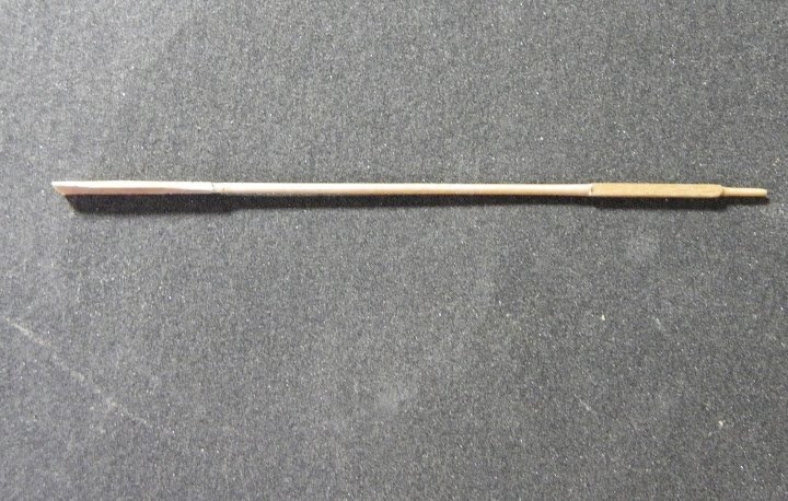
Great idea with the parrels Derek, they look good. 👍 I have made oars at 1:64 scale, I make them by hand, but clean boxwood square stock is required which reduces the breakage rate, but the attrition is still quite high, the blades are also Boxwood. These are examples I made for the Pinnace on Pegasus. B.E.
- 725 replies
-
- 2
-
-
- vanguard models
- speedy
- (and 1 more)
-
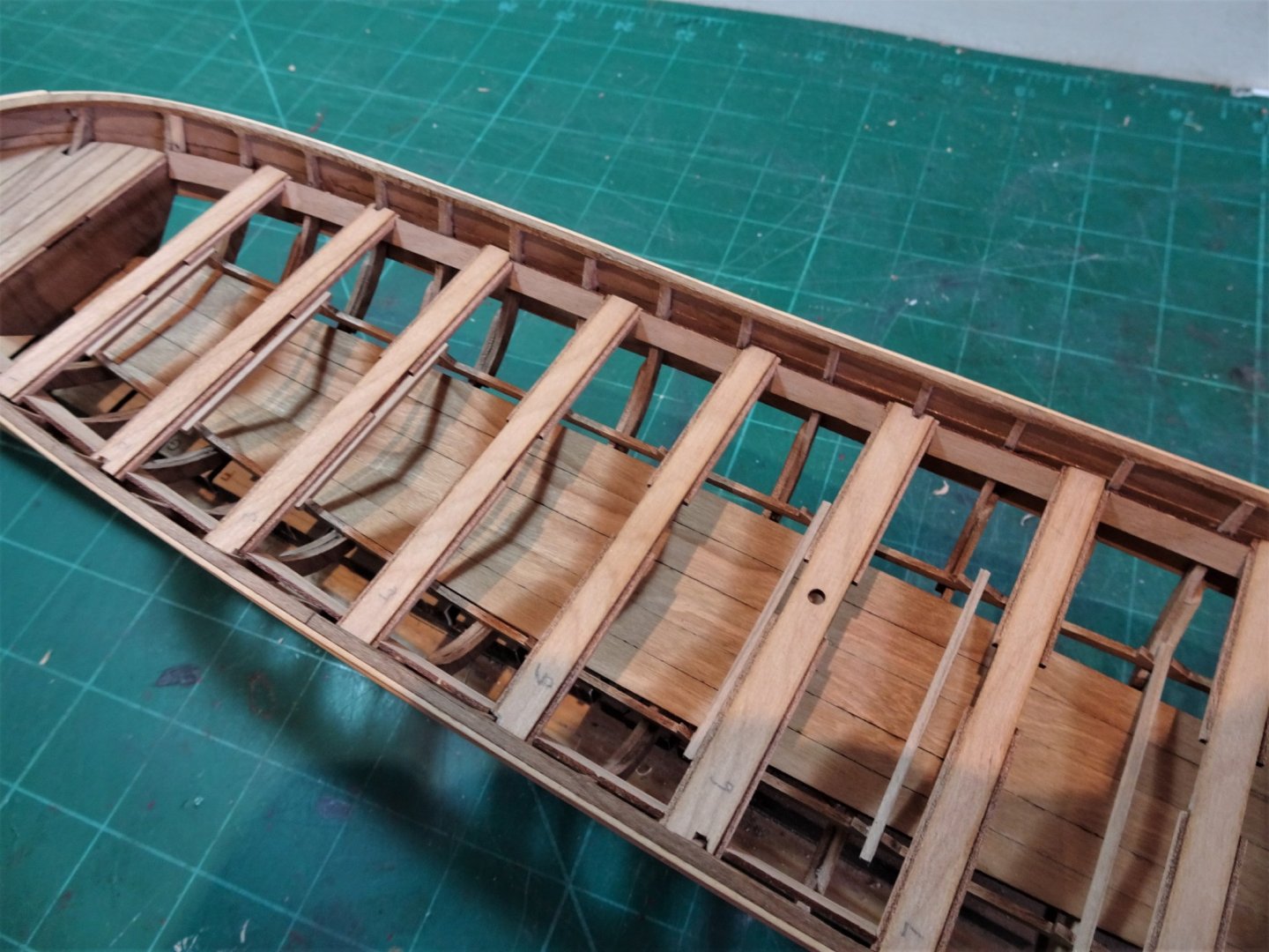
Post Thirty Thwarts n’all I decided to return to fitting the thwarts but before I did I released the one whittled Acanthus decoration from its backing. Hardly a success, it did release naturally but a couple of bits fell off, even more problematic the decoration would not fit between the rails. 1874(2) This is quite puzzling as I measured it accurately, and the resin versions as shown above fits perfectly. The inference is that I haven’t reduced the width of the scrolls and swirls sufficiently, and I thought that they were already pretty thin. I will park this issue until the thwarts are fitted. Fitting the thwarts. My main concern is to ensure that all the cut outs that take the centre pieces are in line once the thwarts are fitted onto the risers. Thwarts 1, 7, and 9 are not much of a problem because they are clear of the frames, but the remainder are blocked from fitting at their full length because the frames at some point inhibit their passage. It looks like Chuck has cut the thwarts on his build shorter to just sit on the risers and up against the frames where necessary. The riser edges are a very narrow surface to support the thwarts, and I envisage problems if there are centring errors with the centre boards. 1871 I opted to notch the thwarts where required which will give me more leeway when it comes to adding the centre boards. The thwarts fitted spot on in the riser notches but as indicated by Chuck, the notches required deepening a tad to allow the thwarts to sit down to allow a close-fit run of the inboard panelling atop the thwarts. 1868(2) Note to self, remember to fit the step for the Royal Standard Flagstaff below thwart six before it is glued into place. 1866(2) The thwarts will now be removed and the risers painted. 1865(2) The next stage is the testy business of cutting and fitting the central boards. B.E 15/05/21
.thumb.JPG.e33cef708da0a61f8813a87ec83191ad.JPG)
.thumb.JPG.2e1706d8664db27ccd6a2f64b8717a76.JPG)
.thumb.JPG.1f17246bb8e879610bdb2ecbea6b359f.JPG)
.thumb.JPG.783747d4c08d5f348bf80d2b3260e15f.JPG)
- 185 replies
-
- 6
-
-
- queen anne barge
- Syren Ship Model Company
- (and 1 more)
-
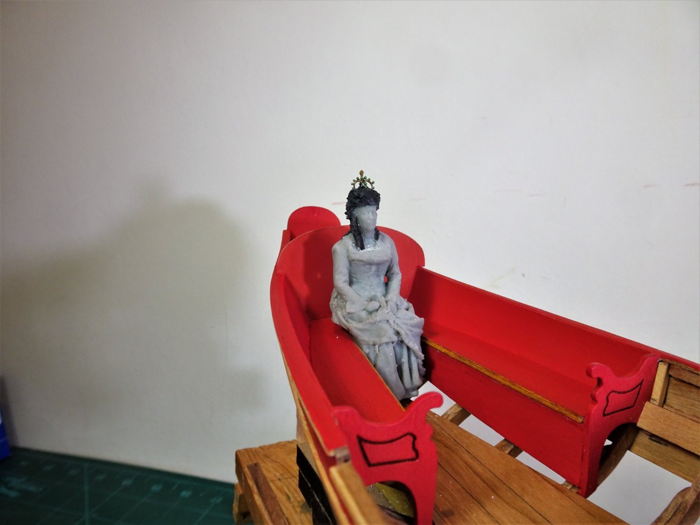
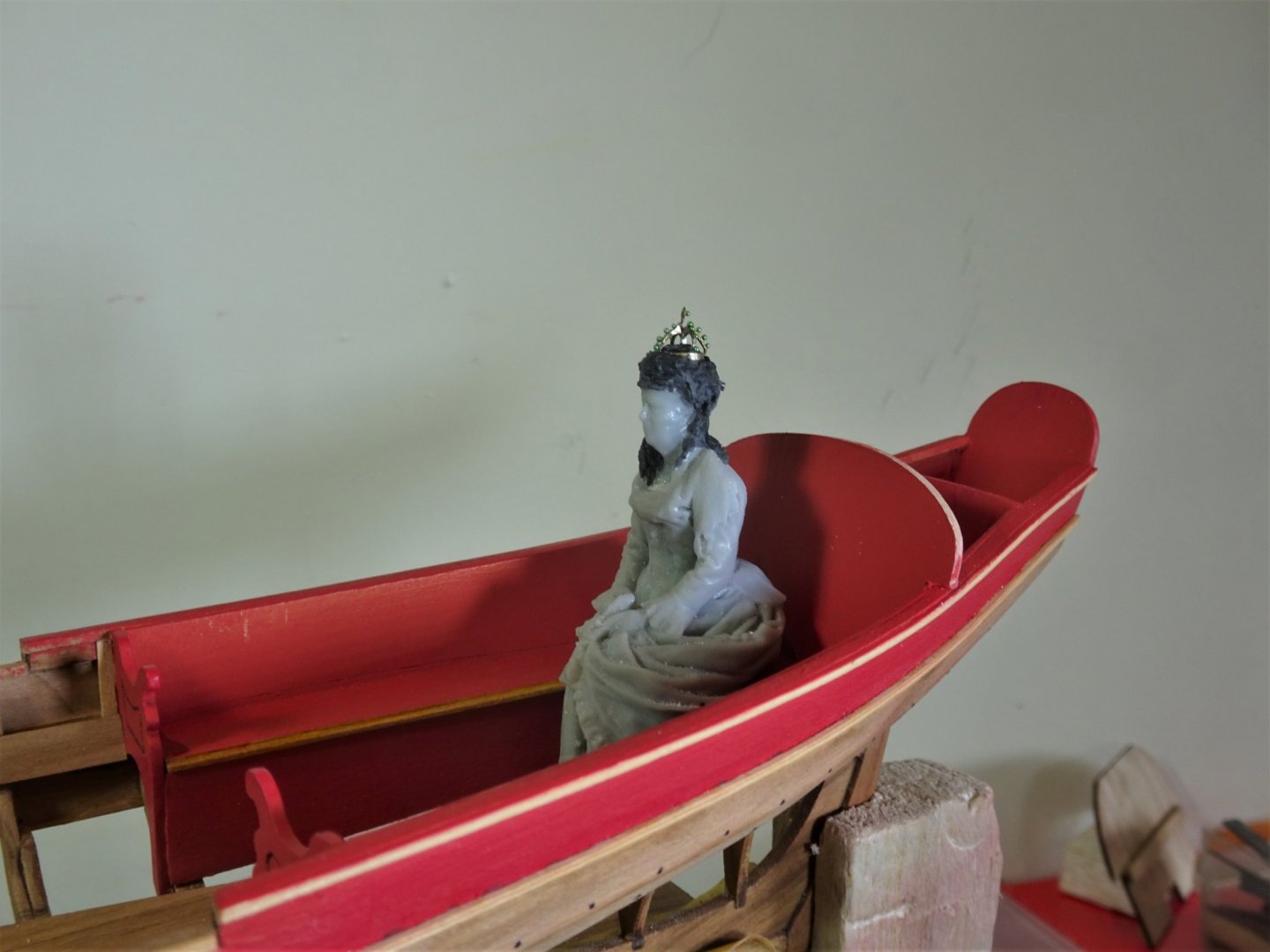
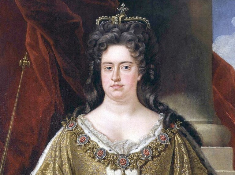
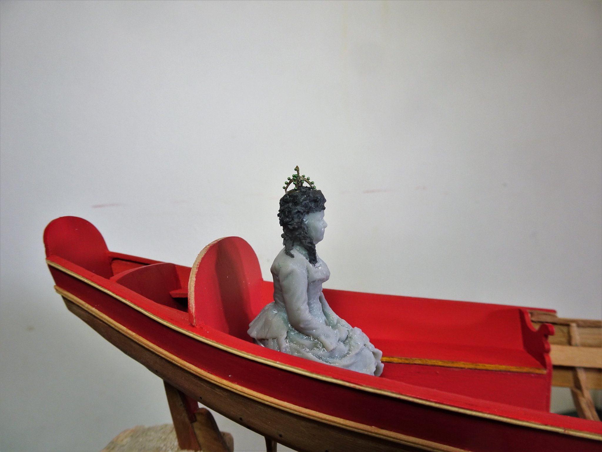
Thanks Chuck, I understand the figure was left unpainted to distinguish that it was a modern (1975) replacement. There’s no mistaking that she is the Queen, dressed in what looks like her Coronation robes, wearing the Imperial Crown, orb and septre in her hands. Interesting that the contemporary model of the Barge has no Flying Transom and is fitted with with tiller lines rather than a tiller. B.E.
- 185 replies
-
- 1
-
-
- queen anne barge
- Syren Ship Model Company
- (and 1 more)
-
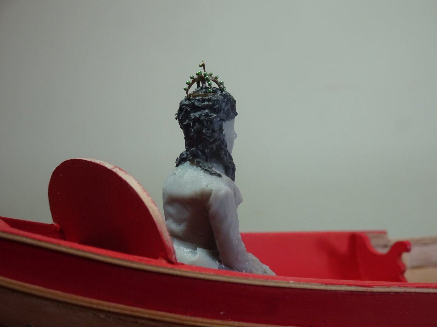
Post Twenty-nine Still in attendance to the Queen Before I put paste to Royal head, I had a trial on a spare figure to get a feel of the how the paste worked, and its working and drying times. The Queen will be wearing a small crown or coronet and I need to establish how this will fit on her hair. 1838(2) Having made a brass ring to form the base of the crown, I could start to form the hair and when the paste had started to set, the ring was placed on the head leaving an impression for the final fit. I then had the task of making up the crown, a tiny thing of 5mm diameter by 5mm high. 1823 The fit looks ok. 1833(2) The parts were silver soldered together and gemstones added in the form of seed beads. 1846 1847 1850 1854 1857 1853 1856(2) Still some tweaking to do, I think the hairline across the forehead needs softening, but I feel that she will now make a credible 18thc figure. I will leave it there now and return to fitting out the barge. B.E. 14/05/21
.thumb.JPG.0c802c738dfd6352eedcf8bc669773ff.JPG)
.thumb.JPG.4997632626277f9cfcb23009c17d5a51.JPG)

.thumb.JPG.c3f8fb474199ebb2ac3d6ba526587ad0.JPG)
- 185 replies
-
- 20
-
-
- queen anne barge
- Syren Ship Model Company
- (and 1 more)
-
I can't get that image out of my head now Hubac.😉 You wouldn't want me around you with a scalpel Derek, I've had two sliced fingers this week.🙄 Thanks Guys, B.E.
- 185 replies
-
- 2
-
-
- queen anne barge
- Syren Ship Model Company
- (and 1 more)
-
Thanks Chuck, As a first move to transforming my Edwardian lady into an 18th Century Queen I had to remove all the hat and hair detail and give her the Virgin Queen look without her wig. 1816 1818 I have left the remnants of a ribbon which will hopefully turn into a ringlet. I used a combination of scalpel, chisel, and files to perform the task. The tricky part was removing the rim of the hat which came down over her forehead. The next stage is to recreate the ringlets and curls piled high on her head and tumbling down over her shoulders. Easier said than done I suspect. For the purpose I will be using Windsor and Newton heavy carving modelling paste to build up the hair by layers and hopefully give her a hair style fit for a Queen. B.E.


- 185 replies
-
- 11
-
-
- queen anne barge
- Syren Ship Model Company
- (and 1 more)
-
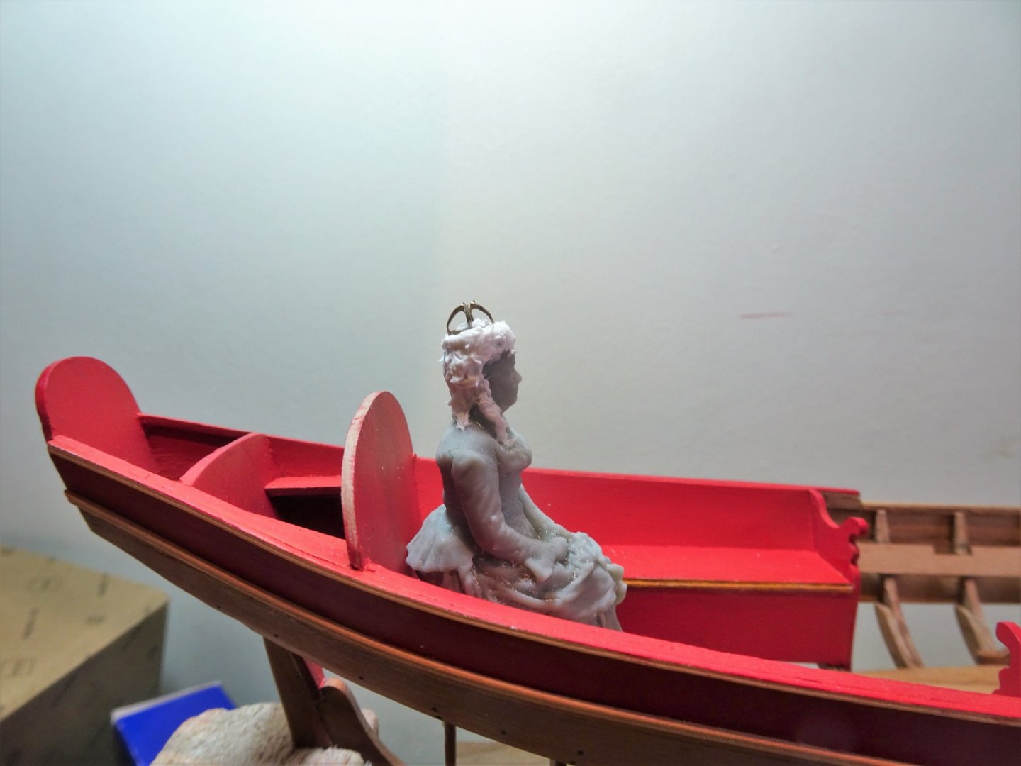
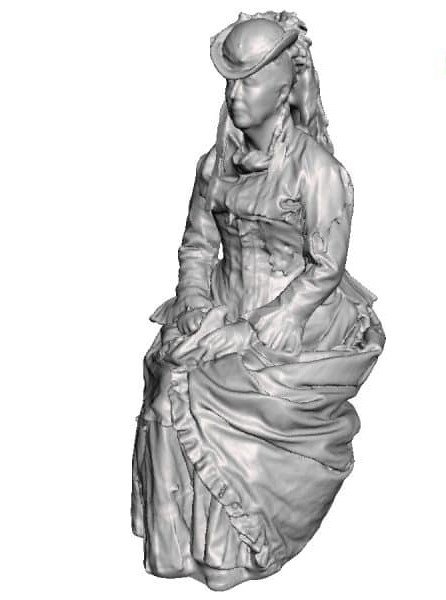
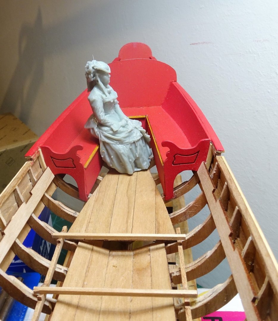
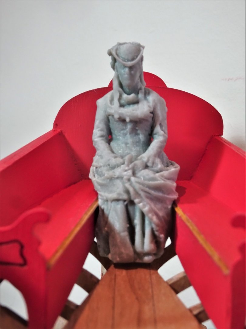
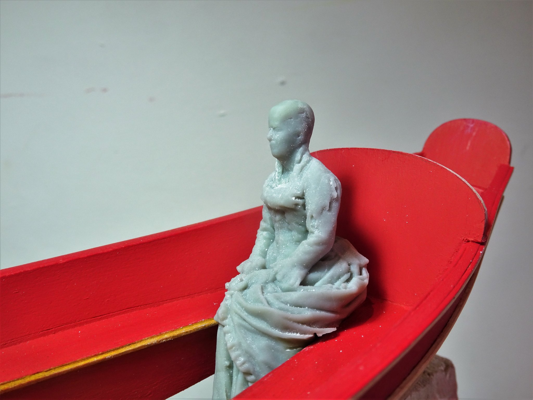
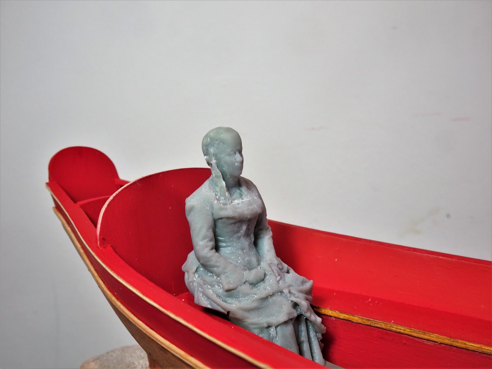
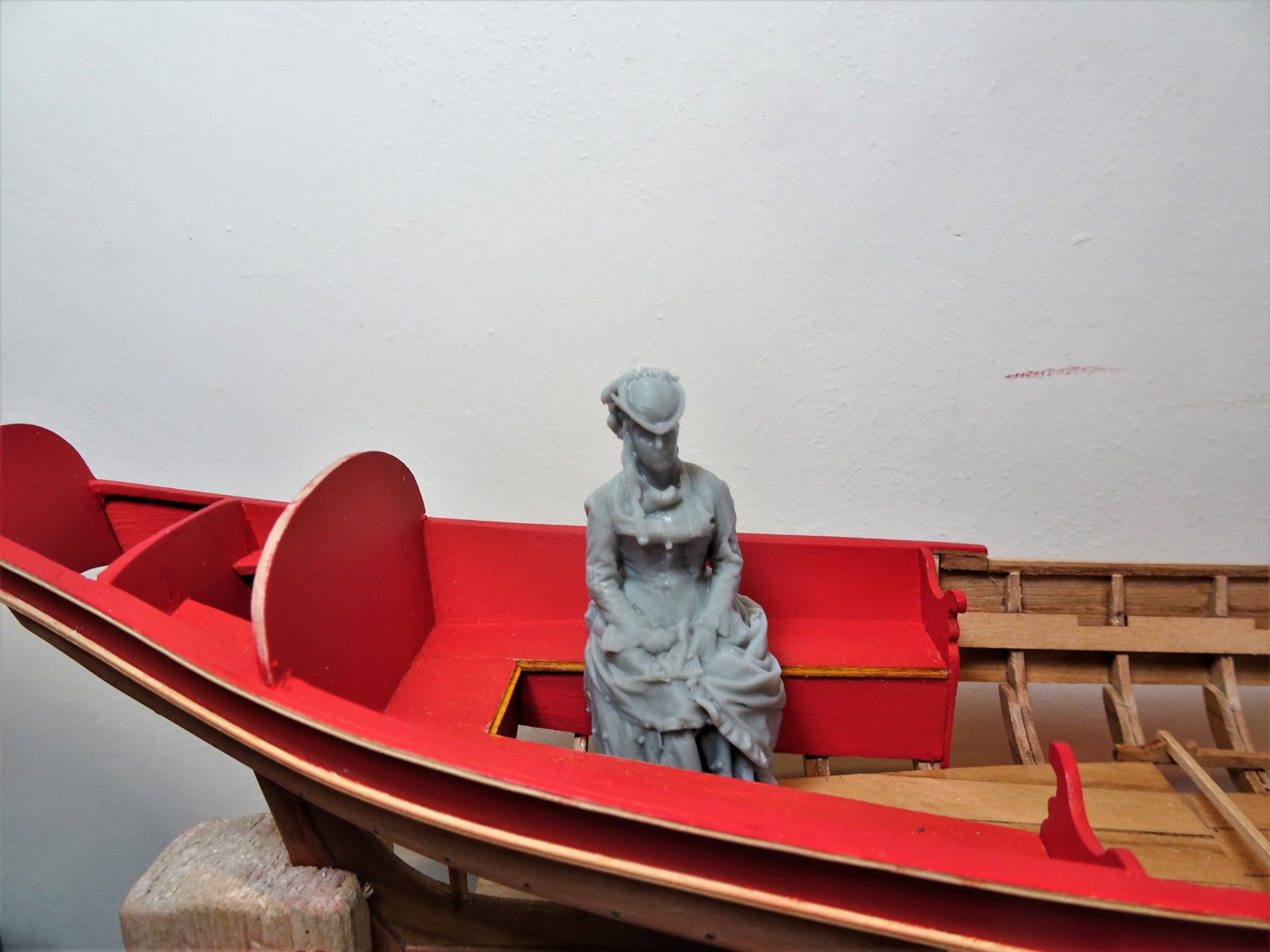
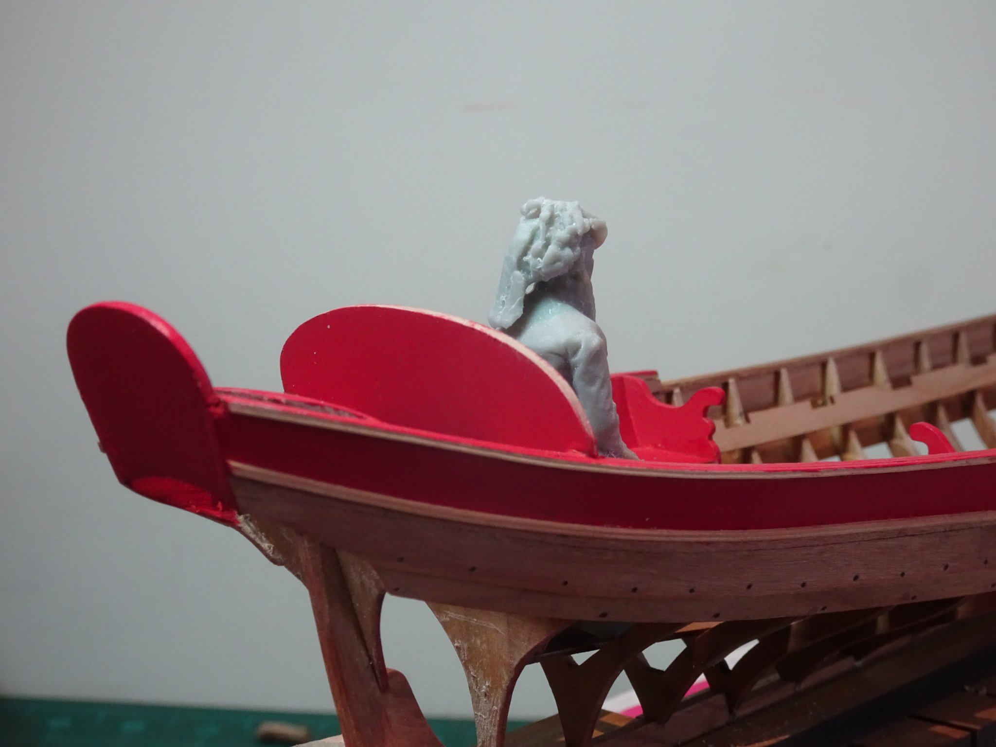
Post Twenty-eight A small diversion – an inspection visit by Royal decree. I mentioned a while ago about crewing the barge and today my ‘Queen Anne’ arrived to audition for the part. She is an Edwardian figure at 1:24 scale produced by Modelu in the UK. 1508 She represents one of several sitting figures designed for a model rail setting and produced in various scales. 1808 As can be seen she is good fit for the Royal Barge. 1806 The lines and folds of of her long dress are also a good fit, altho’ the head will require some surgery to replace her hat with the more voluminous hair style of the early eighteenth century. Queen Anne 1812 A little surgery was required to her clothing to allow her to sit square in the Stern sheets. 1813 1814 1811 1815 I will continue to modify her appearance, but I need to get back to the main event. B.E. 13/05/21


- 185 replies
-
- 15
-
-
- queen anne barge
- Syren Ship Model Company
- (and 1 more)
-
Thanks Glenn, The chisels are made by Swann Morton. This is the supplier I use in the UK, but they are available from many sources. Swann Morton Fine Blades and Handles Range - Scalpels & Blades (scalpelsandblades.co.uk) The SM61 Blade is 1.5mm and the SM62 IS 2.5mm. I couple them with an SF2 handle - 103mm. Regards, B.E.
-
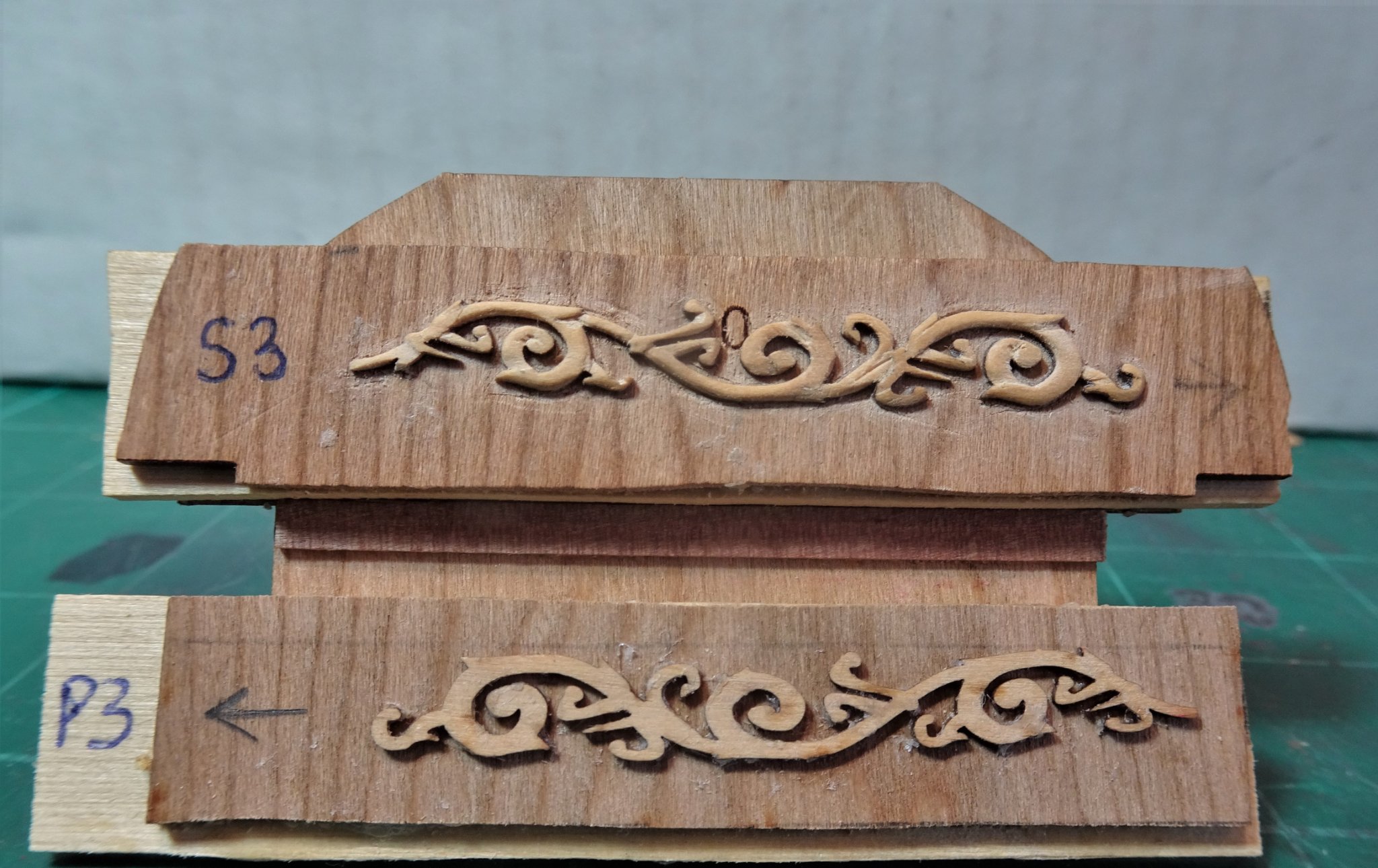
Post Twenty-seven Hull decoration This consist of seven strips of Acanthus leaf decoration (three per side) Boxwood blanks are provided, and whittling consists of stop cuts, paring, and rounding. More complex than the Monogram because tight curves present greater difficulty. Fortunately, Chuck has provided excellent large-scale drawings indicating the stop cuts, the positions of which are transferred to the blanks. Again, there is a fall-back position in the form of a resin version of the decoration. Knowing that it is available reduces the ‘fear’ factor in starting this task. 1798 The aftermost section being progressed, the corresponding blank below it. Chuck's fine examples. This is what I’m aiming for… 1795(3) … and this is the reality as work progresses on the aftermost moulding. A couple of extremities have broken away but were re-attached with water-proof glue. The tiny scroll at the Transom end pinged off into the ether never to be seen again. Fortunately, this is the end that may require trimming to fit so its absence may not be missed. The depth to the moulding is beginning to show as the stop cuts and paring take effect. As the sharp square edges of the blank pattern are softened it is starting to resemble a decorative moulding, but still a long way to go, but I will persevere. As luck would have it my replacement thwarts arrived this morning which means I can return to the main event and progress the whittling at a more leisurely pace. B.E 08/05/21
.thumb.JPG.498d6bdc372ea645c732e6ae3d18b823.JPG)

.jpg.25a817ba353c31bfe01b4e075c42c49c.jpg)
- 185 replies
-
- 8
-
-
- queen anne barge
- Syren Ship Model Company
- (and 1 more)
-
Thanks Chuck I will persevere with the Acanthus leaves, and hopefully they will make the cut so to speak. 😀 @ Glenn, Lack of patience, I don't believe it, given your exemplary work on Cheerful. I wish my completion was in the plural, the acanthus leaves are still the blanks, only the Monogram has received chisel and knife. 😀 B.E.
- 185 replies
-
- 2
-
-
- queen anne barge
- Syren Ship Model Company
- (and 1 more)
-
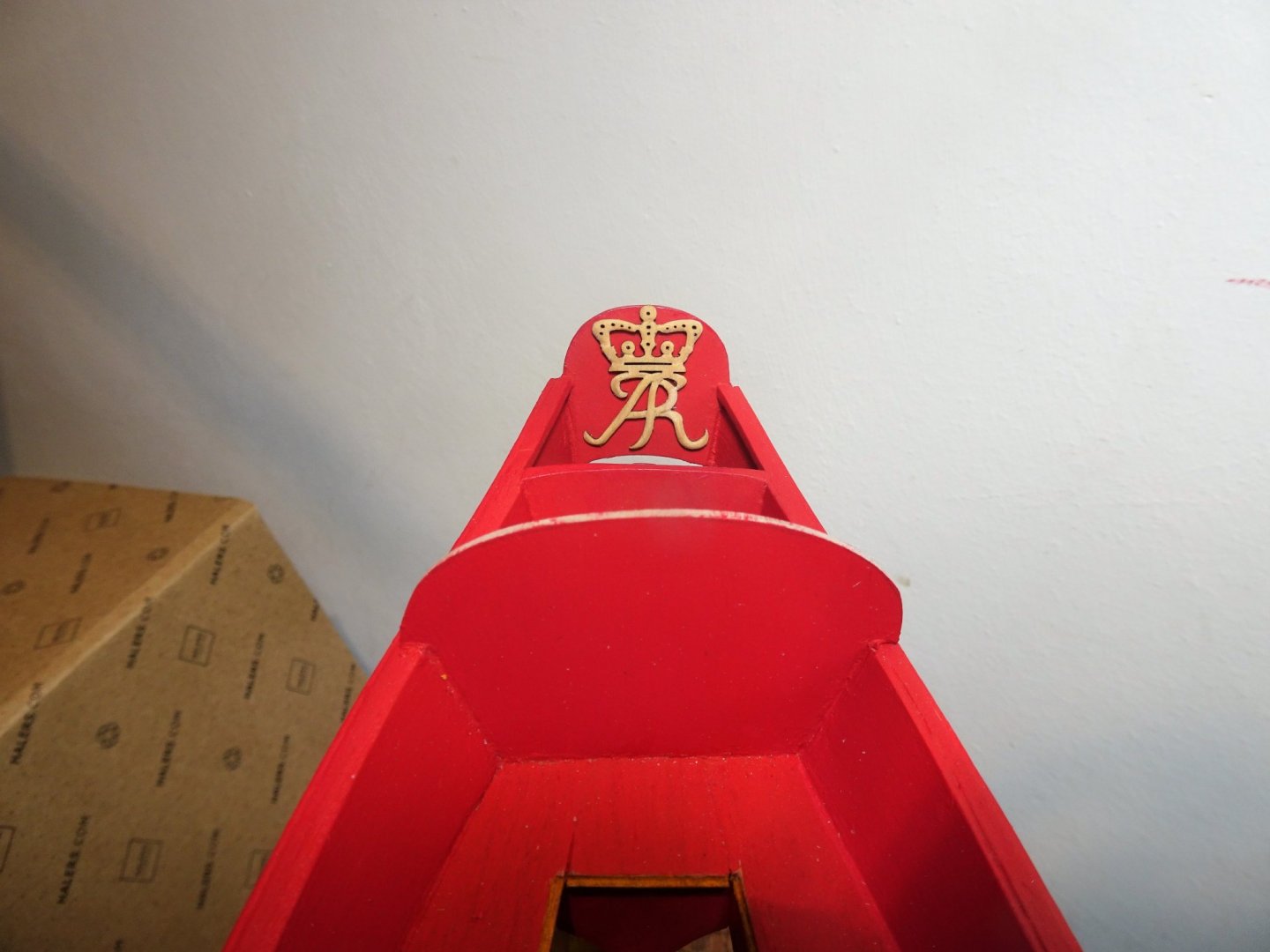
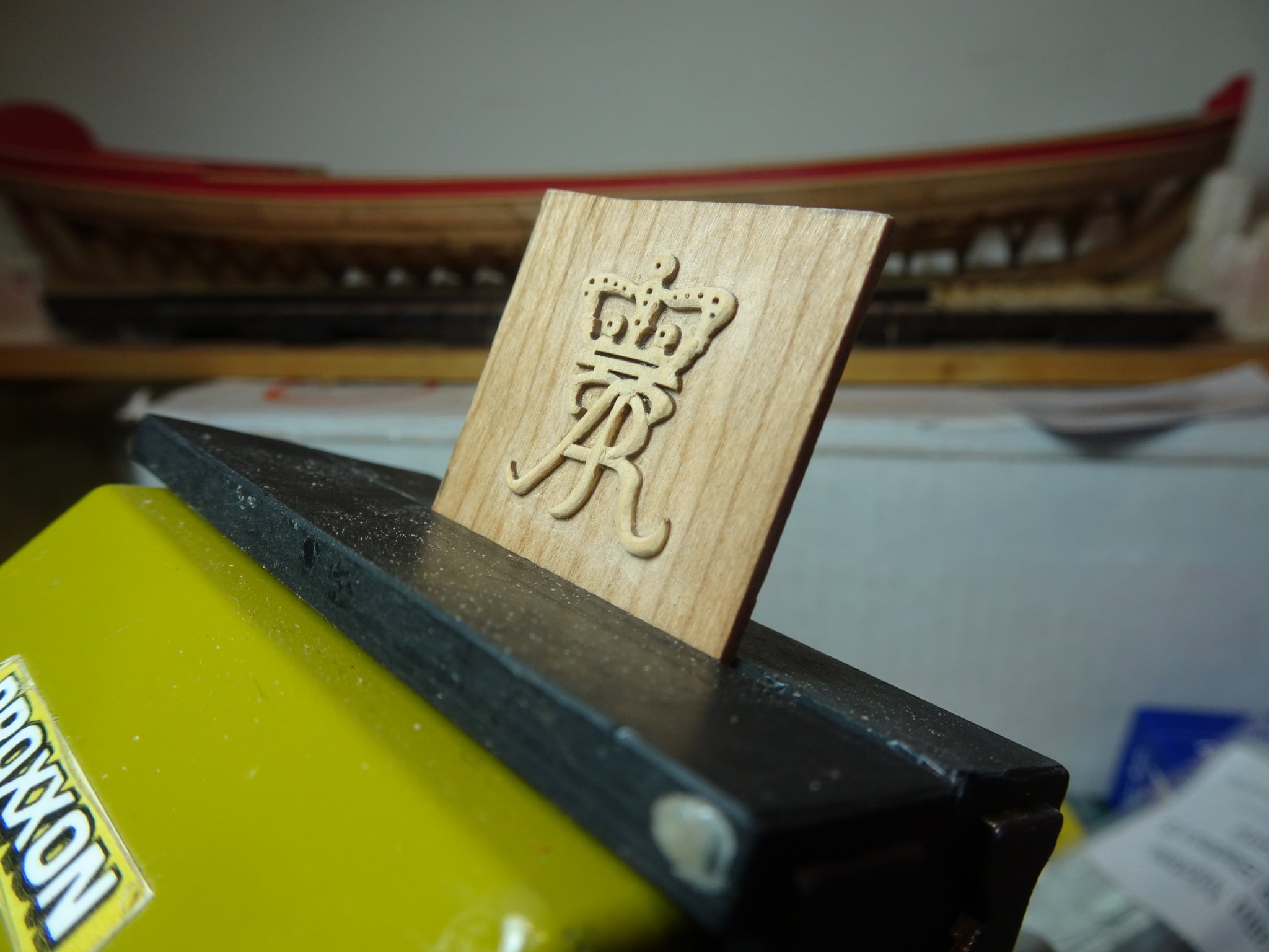
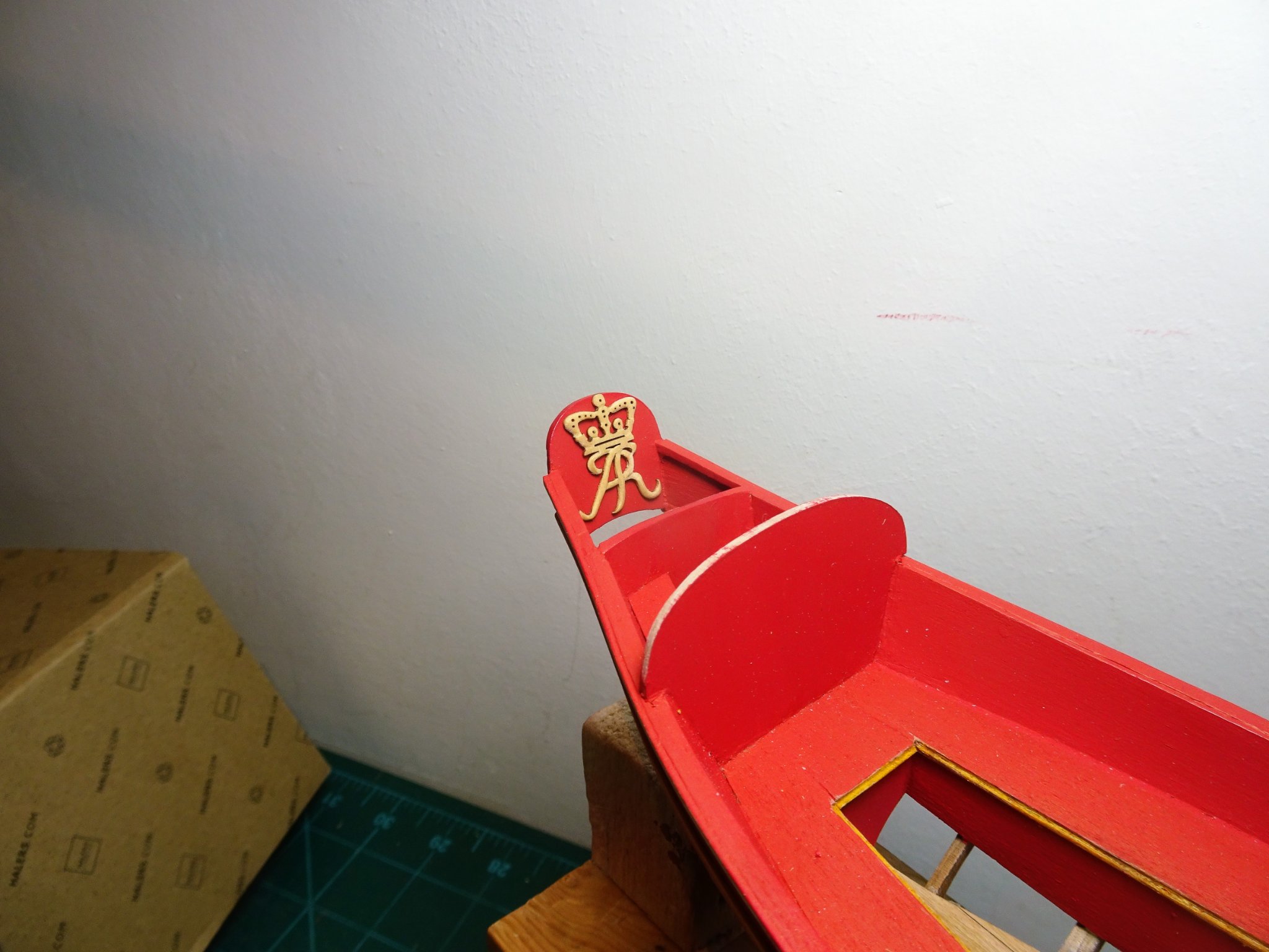
Post Twenty-six A little more whittling I continued to fettle the Monogram using a combination of micro chisels and sanding sticks shaped to fit in the nooks and crannies in an effort to impart some round to these tricky areas. Chuck makes reference in his log to ‘Analysis Paralysis’ 1759 Each check of the macro lens reveals tiny areas displeasing to the eye that are not there at a viewing distance of eight inches, and even less so on the model. 1763 Once I reached the point of satisfaction to my admittedly old eyes, but assisted by the optivisor, I brought proceedings to a halt. The Monogram was placed in a small container of Isopropanol to free it from the backing. I had used a thin smear of dilute pva (non waterproof) to secure it but even after four hours it showed no sign of releasing. At this juncture I did what Chuck wisely advises against. I tentatively slipped a scalpel point beneath the top part which has the least fragile parts, and gently eased it a fraction before replacing it in the alcohol. I repeated the process a few times until I could get a sliver beneath it thus allowing greater access to the alcohol. Over the next two hours, by degrees, I eased the part until it came away intact. Macro views of the Monogram temporarily in place on the Flying Transom. 1793(2) 1788(2) 1790(2) From a normal viewing distance as gauged below, it looks ok to my eye. 1783 1792 I will leave as is for the present and turn my attention to the hull decoration. Even tho’ I escaped without issue with the Monogram, I think the pva is perhaps a little too strong for the purpose, so I purchased a Pritt stick to temporarily secure the hull decoration. I took the precaution of doing a test piece before committing to the real thing, and release was much easier after around four hours. 1771(2) The decorations have been labelled to run fore to aft and I was careful to ensure I had the Portside decorations the right way up to mirror the Starboard set. Looks like I’ll be whittling away for a while yet. B.E. 07/05/21


.thumb.JPG.ce2f27b1acf934fa83e9a2585cf139c0.JPG)
.thumb.JPG.2eda5394499ae7e4233d022394a57c5d.JPG)
.thumb.JPG.096df6570d870f125070a29fcb05aea0.JPG)

.thumb.JPG.4c3c8162cbd356ed60a4e217af6a0349.JPG)
- 185 replies
-
- 14
-
-
- queen anne barge
- Syren Ship Model Company
- (and 1 more)
-
I think the Press was a predominantly British thing particularly in the 18th /early 19th centuries. Britain had a large empire, was mostly at war from the late 18th c to the end of the Napoleonic era, and had a huge standing navy, in constant need of crews. British sailors were rarely allowed shore leave. By comparison the French Navy which spent a lot of time blockaded in their ports even allowed crews to live ashore. I've not heard of foreign navies operating a 'press' but as Welfalk says Land army recruitment, also in the British army, didn't pay too much attention to civil rights, promising long to potential recruits, and delivering a very different reality. B.E.
-
That's a relief Chris, fingers crossed for a speedy recovery. B.E.
-
Hi Glenn, your masting and rigging is an equal to the beauty of the completed hull.👍 For the extent of progress, twelve months seems quite speedy given the quality of your work, hardly a blink in time.😀 I spent 18 months on my Cheerful, and I didn't mast and rig her, and my Pegasus build was seven years on the stocks to completion. Regards, B.E.
- 778 replies
-
- 2
-
-
- cheerful
- Syren Ship Model Company
- (and 1 more)
-
Thanks Chuck, I'll carry on smoothing 🙂 Quite enjoyable doing this, almost therapeutic, a great idea to provide the makings and opportunity to have a go. B.E.
- 185 replies
-
- 1
-
-
- queen anne barge
- Syren Ship Model Company
- (and 1 more)
-
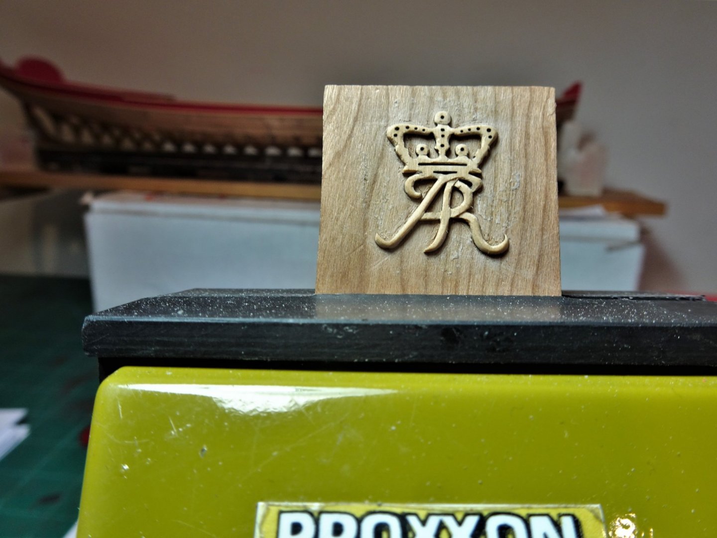
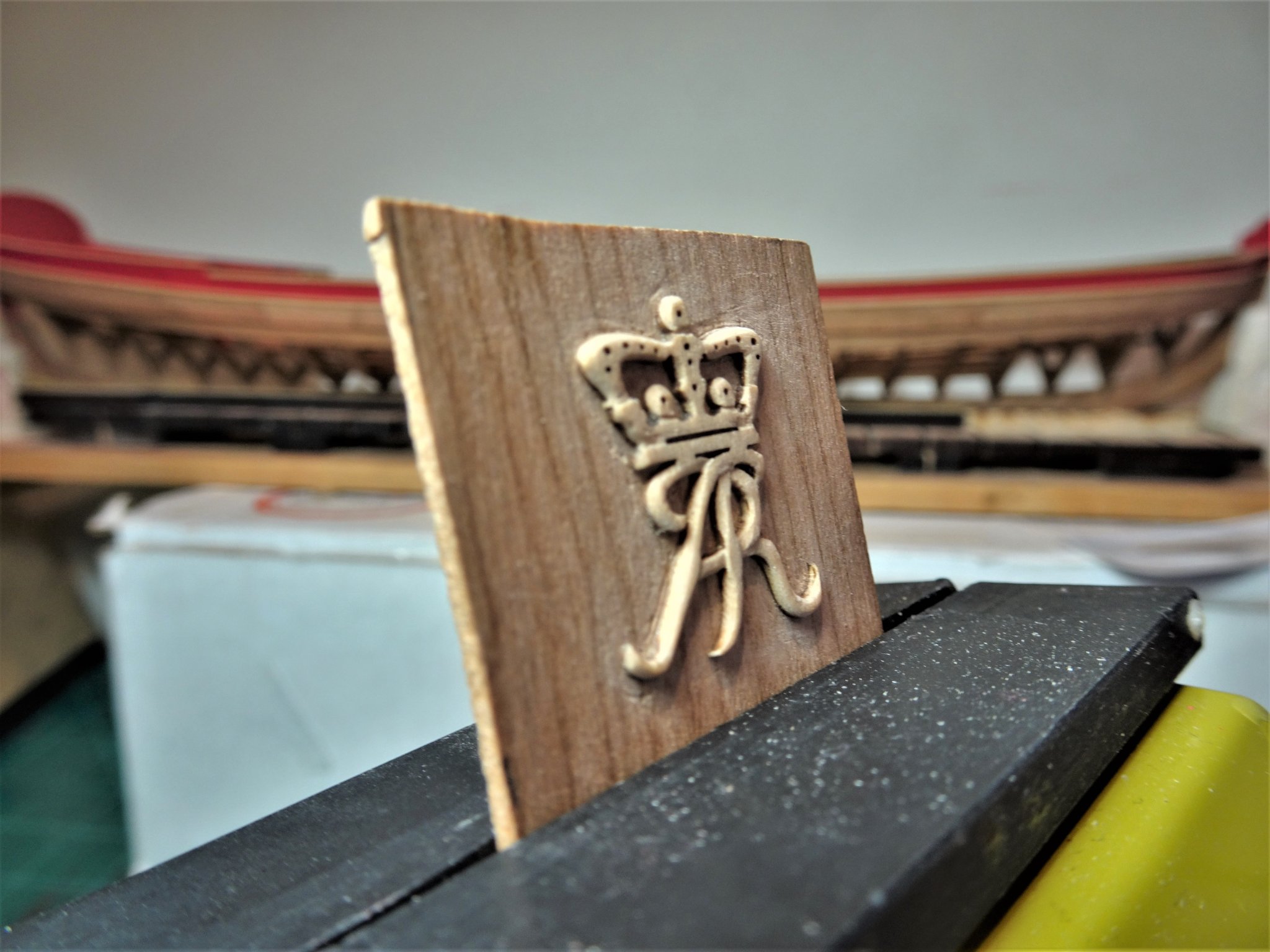
Thanks Rusty, and to those who have posted 'likes' Post Twenty-five That subject of carving Chuck has very thoughtfully provided some nice Boxwood blanks for the decoration of the barge, to give us an introduction to carving. In practice it is more like adding definition and a rounding to the profiles, but even so, easier said than done. If all else fails, and exasperation wins the day, there is the fall-back position of a resin set to take away the pain. 1738(3) My assembled kit to tackle this first foray into this new adventure. As suggested, I am starting with the Queen Anne monogram. 1749(2) The 'carving' in progress. 1750(2) The Swann-Morten micro chisels at 1mm and 2mm widths work well along with the No11 scalpel blade. 1751(2) The rounding and the deeper profiling of the letters can be seen in these shots. 1756(2) From left to right, the wip Monogram, the Resin version, and the original blank. Even at this stage I am preferring the look of the Boxwood versions, altho’ I think the Resin version would look better once coloured. 1749 The question with all exercises of this type is when to stop. I think a little more smoothing, and softening the rounds, but the more you do the greater the risk of a breakage. I will make a back-up Monogram just in case. B.E. 06/05/2021
.thumb.JPG.3cdf07babf523d2df250332ac564f5cf.JPG)
.thumb.JPG.2e75f2911e6db7c77edc6f00badf3bf3.JPG)
.thumb.JPG.3df66838cf368dbd08307700bee44c8b.JPG)
.thumb.JPG.5833d0ec351b747f549170788ce2ea72.JPG)
.thumb.JPG.9eb90016a757a9fb9dbb1b7f704d81c1.JPG)
- 185 replies
-
- 11
-
-
- queen anne barge
- Syren Ship Model Company
- (and 1 more)
-
I hesitate to say Peter, but there are 15 placed around the house, 1 wip, and 1 under the bench. There are also several laid up in ordinary in the loft. You can probably deduce why I am now concentrating on relatively slim models. 🙂 B.E.
- 366 replies
-
- 4
-
-

-
- bellerophon
- victory models
- (and 2 more)
-
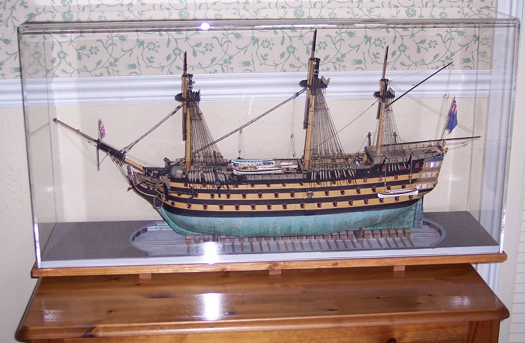
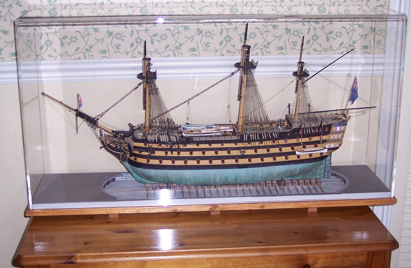
I appreciate your problem Peter, I too would be reluctant to cut a build short having put the work in, and Bellerophon would look magnificent fully masted and rigged. I had prepped the Topmasts and the Main Yard for Victory when reality cut in and I had to accept that I simply didn't have a suitable location for a fully rigged version, the house is already full of models. My solution was to rig the topmasts in the lowered position using the heel ropes to secure, a sort of re-fit display mode. I have now given up building large square riggers to avoid the torment of the decision making. 🙄 B.E.
- 366 replies
-
- 3
-
-
- bellerophon
- victory models
- (and 2 more)
-
Love the lighting in that last photo Peter. 👍 If space is going to be a serious problem, you could always display her with lower masts and standing rigging only and without yards. It is an option I had to take with my Victory build due to the space issue. Regards, B.E.
- 366 replies
-
- 7
-
-
- bellerophon
- victory models
- (and 2 more)

.JPG.44e50a9d7d364a1349b0701e17d3fe59.JPG)
.JPG.6de7026c6464b96c3cf52bffda551c74.JPG)
.JPG.ef18185801f3d3b7ecc6e755de36deb0.JPG)
.JPG.9a0a764726c1b391d12c9f52f7a9e184.JPG)
.JPG.c2634728830ac8aa2e4b26223dceb4f6.JPG)

.JPG.59559e6a155c439d2e5418a7f1624754.JPG)
.JPG.22cfcf07c17575f1f0795331e239ffdf.JPG)
.JPG.fbe46c8bee31d330c21f722e3b794999.JPG)

.JPG.49c7855d725c2e3bd46a2b87a922d99e.JPG)

.JPG.f8e15f704e595b055290de3932477669.JPG)
.JPG.ca0b1fa70dcbd62e657f7e6568b63096.JPG)


.JPG.f7eb9d41cc327d19c66735fc0666ebbe.JPG)


.JPG.432c5868db04c679702d8986045a3a9e.JPG)
.JPG.a5e71d66b336012ed409a8b128804d8c.JPG)

.JPG.62d680f081f6e55336dab60c307f95f2.JPG)
.JPG.98689162bd70c299344787e00a70c58e.JPG)
.JPG.9a7498141c1fbc50c4967365cad4379b.JPG)
.JPG.cef85b995a5fe74326088bb93391463c.JPG)
.JPG.cb8b9d3be9ad97ba44d9306b63f7d986.JPG)

.JPG.0c31de1dc986d3f1208d69f1e10d5e89.JPG)
.JPG.459308b8acdd9d172d0b72361fc16b73.JPG)
.JPG.f7b65e0b160583ff0056462d27911d87.JPG)