.JPG.ca33079f5815b861e67b9c2cccd37982.JPG)

Blue Ensign
-
Posts
4,572 -
Joined
-
Last visited
Content Type
Profiles
Forums
Gallery
Events
Everything posted by Blue Ensign
-
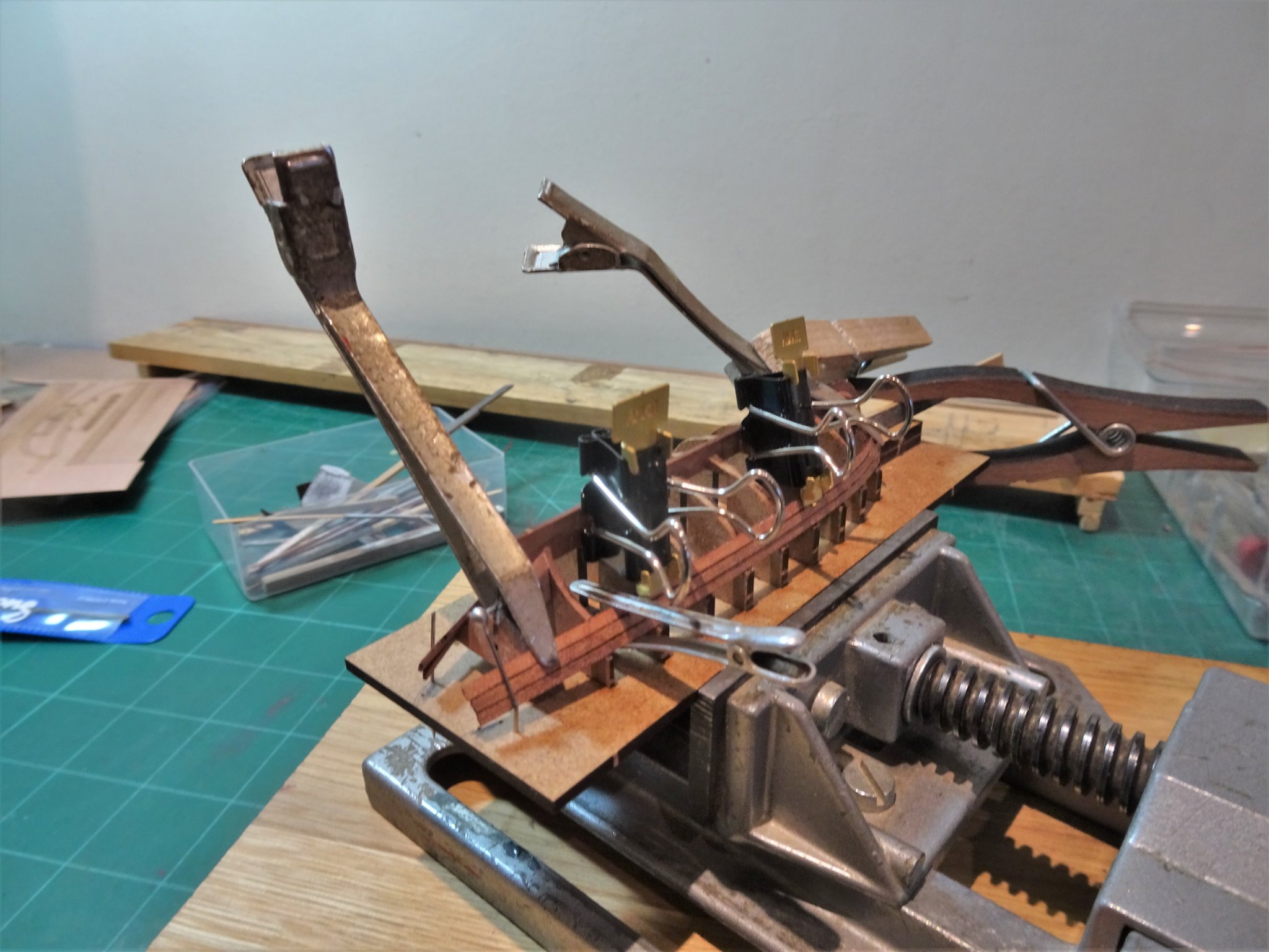
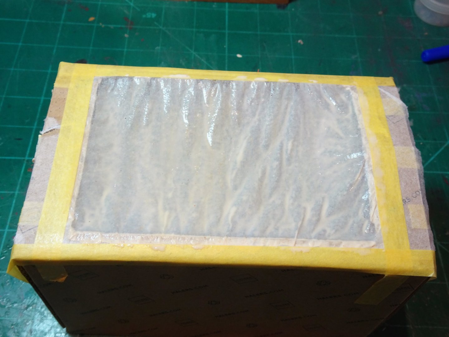
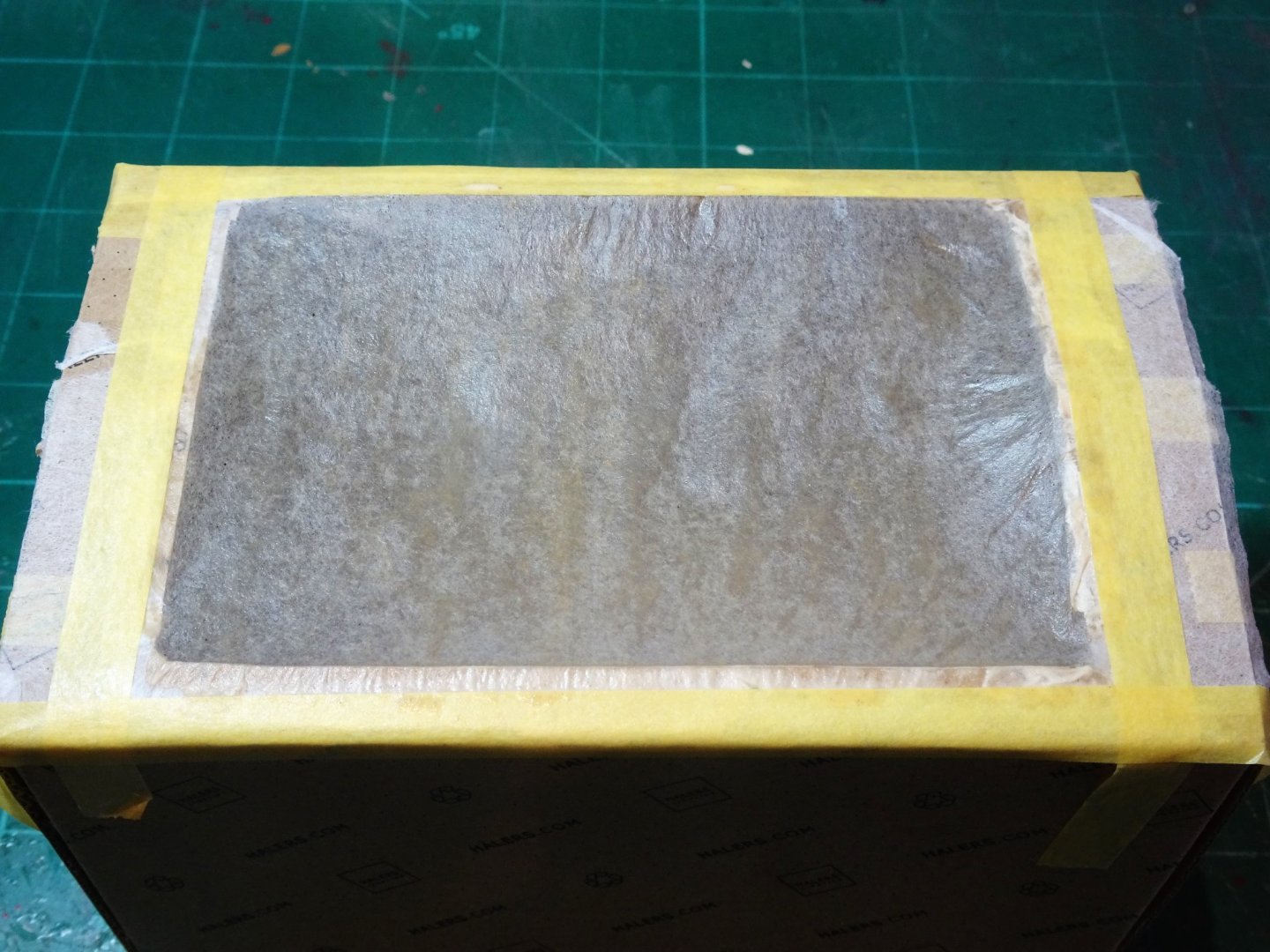
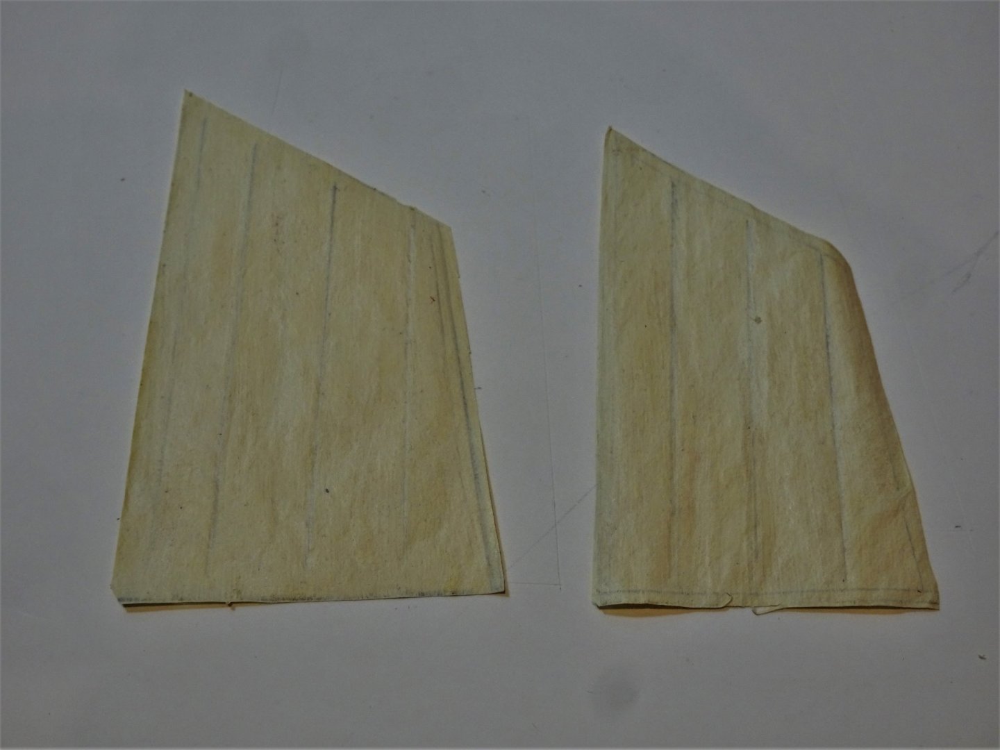
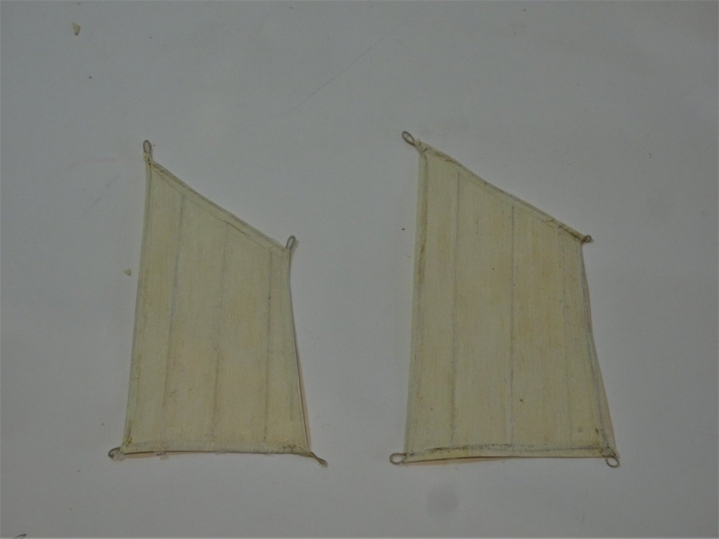
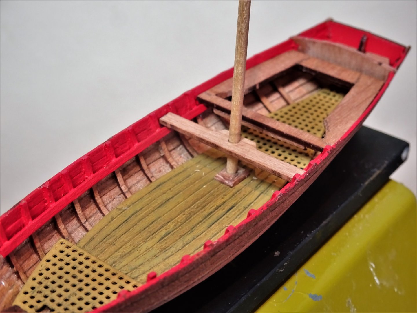
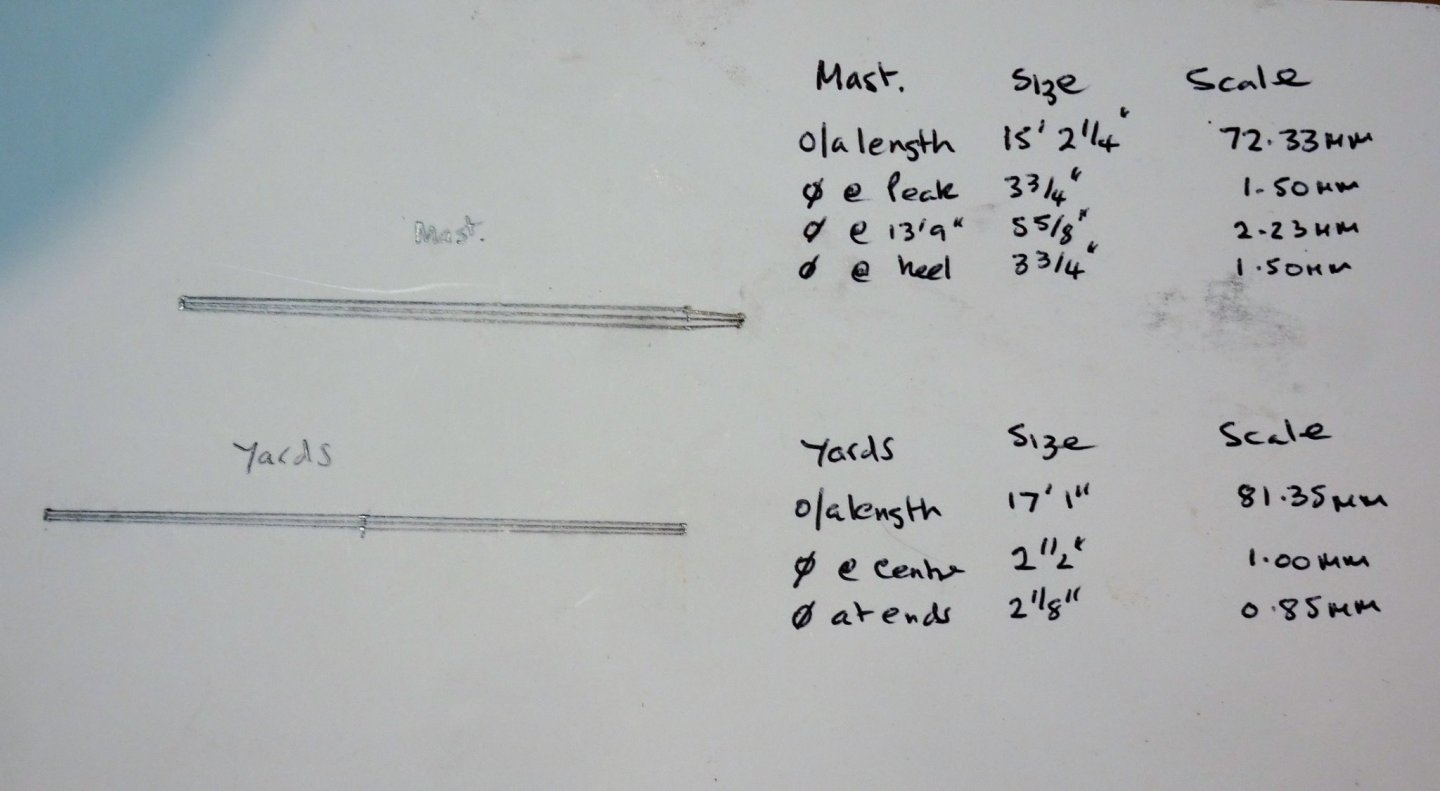
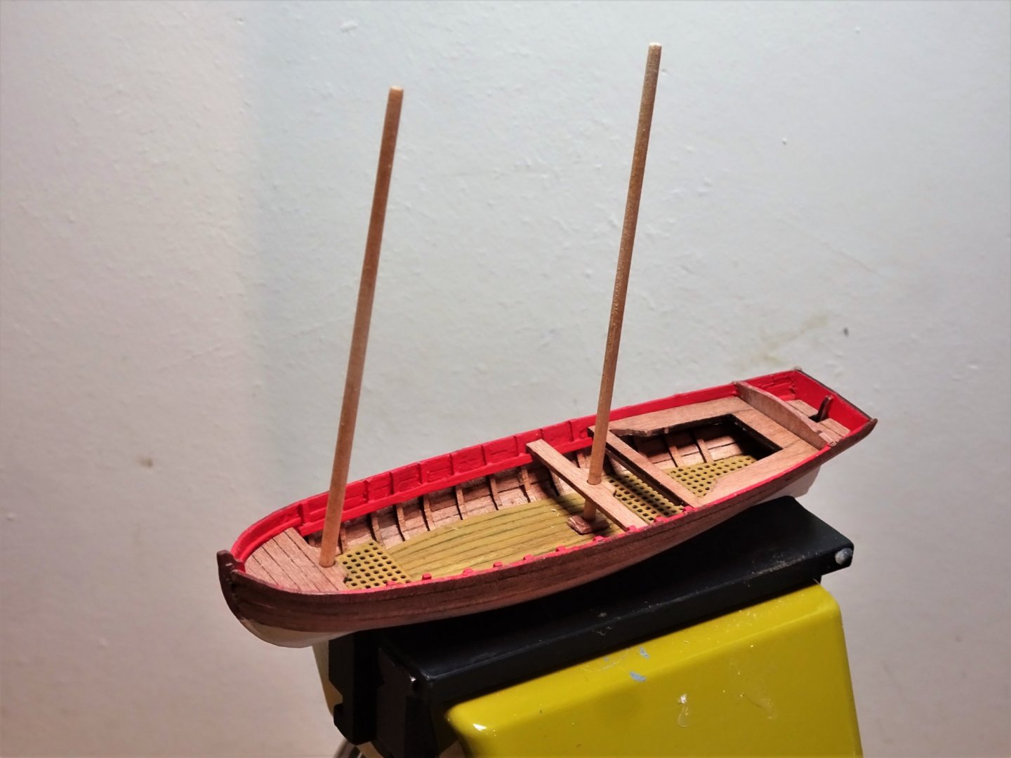
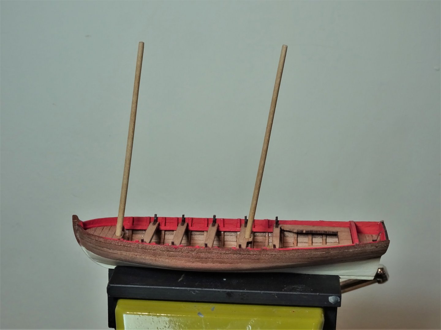
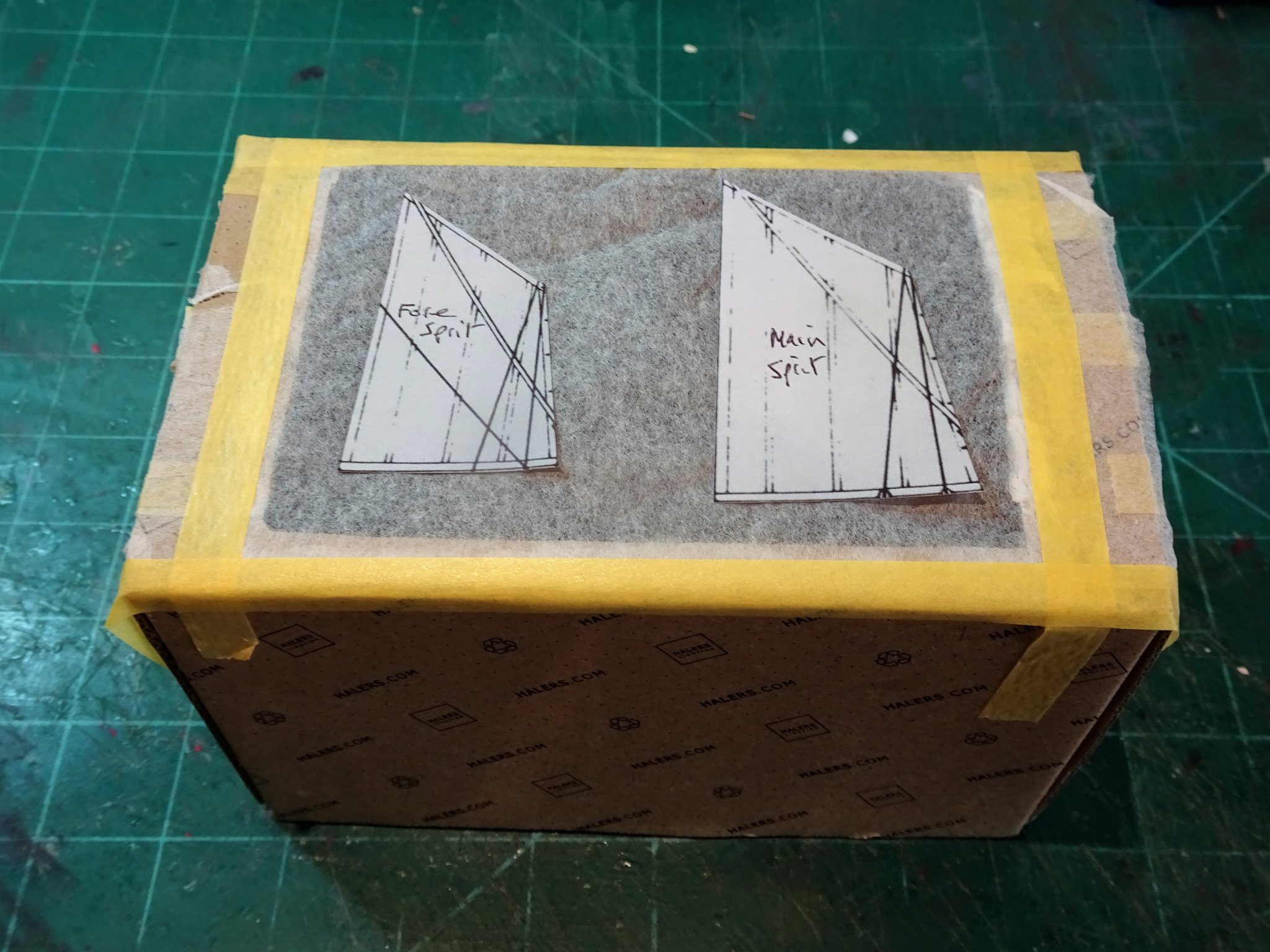
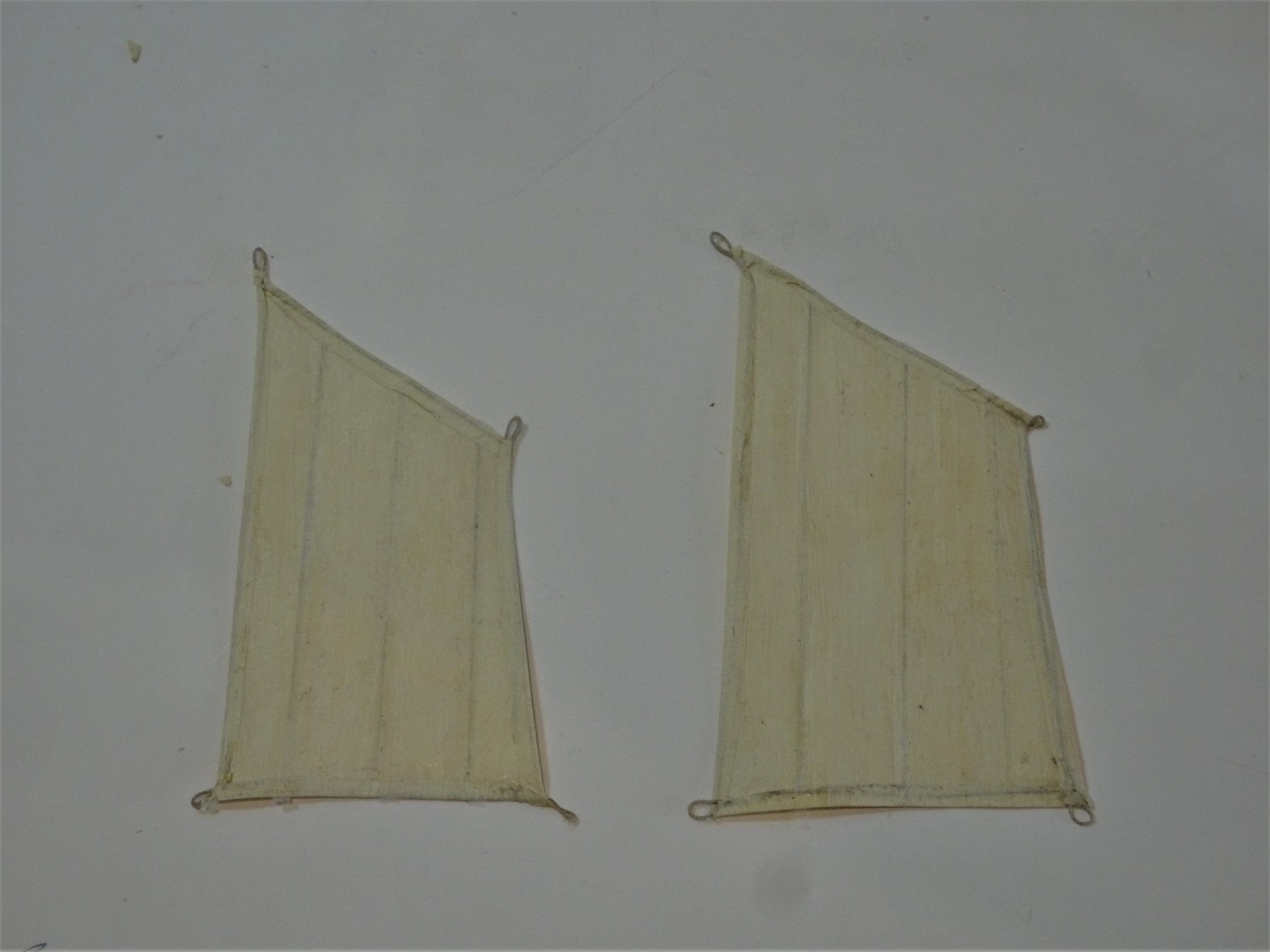
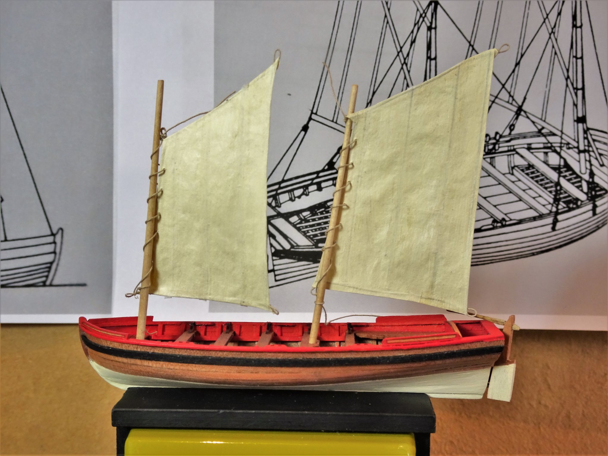
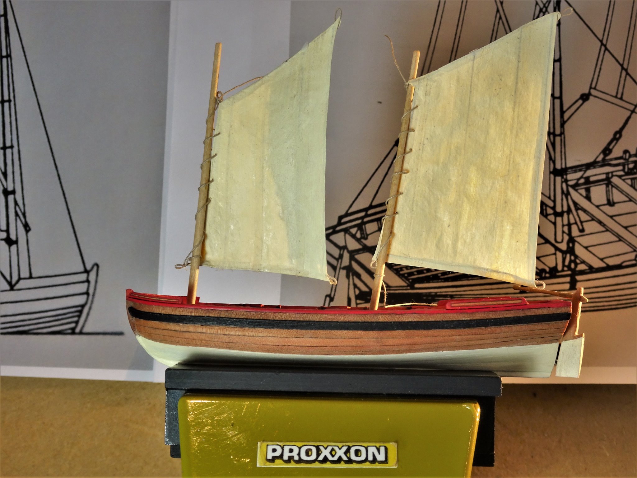
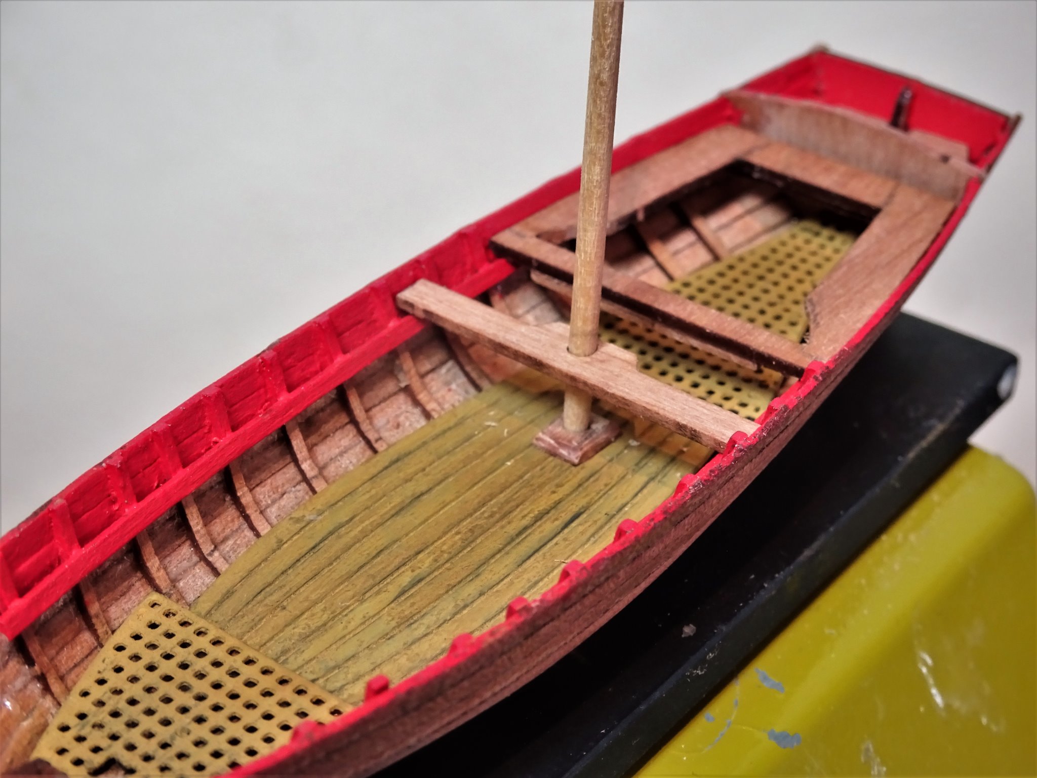
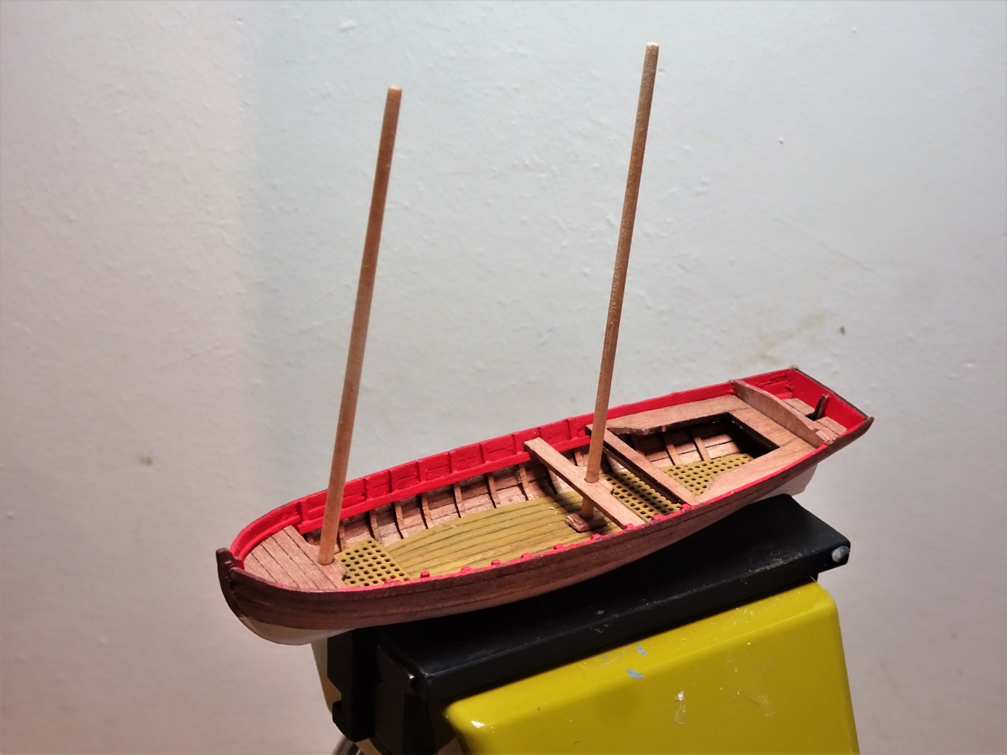
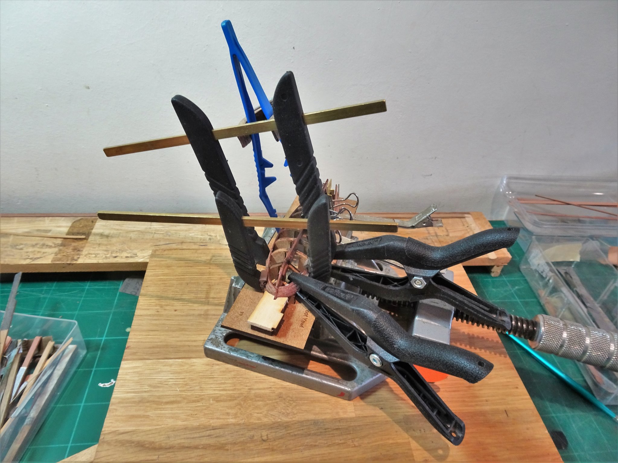
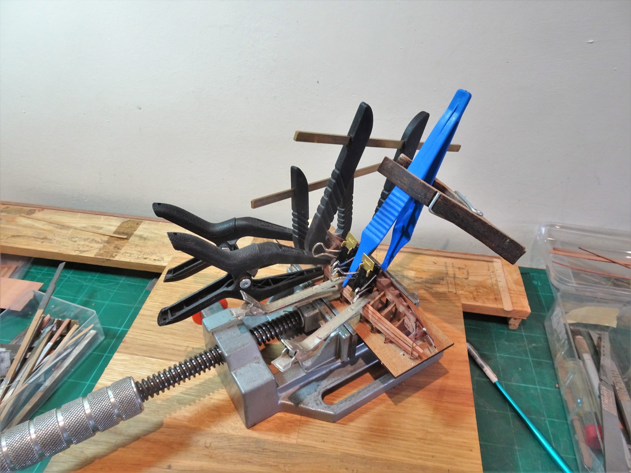
 Post Sixteen Thinking about the rigging. I first needed to work out the relative scale sizes of the masts and the sprits. For this I go to Steel who gives the dimensions in his 1794 work. The mast lengths are 2½ times the breadth of the boat which gives a mast length of 72mm. The Sprit lengths are ⅛ more than the length of the mast giving a length of 81mm. Steel also gives the relative details of the sails. The sails will be made from 21gsm Modelspan using a re-scaled plan. I had to go back eight years to my Le Praetorian build to refresh my memory on making small scale sails. 0448 The Modelspan is taped over a cut-away box, ensuring it is large enough to cover the required sails. 0450 Diluted pva slightly discoloured with yellow ochre, is painted over the Modelspan. 0453 Hairdryer on hot is used and the Modelspan dries taut. 0455(2) The Modelspan is removed, taped over the patterns, and is cut out leaving a margin. 0458 The sails are overpainted with a diluted off-white water-based paint. 0460 The hems are folded over and 0.2mm line is used to form the bolt ropes with cringles in the four corners. Pva is used to seal the hem. Before I proceed further, I need to test check the fit of the sails and work out the position of the Snotter to take the heel of the Sprit. 0469(2) The sails are only roughly laced to the mast at this stage. 0467 0476 I think it will be easier to rig the sails off-model. B.E. 11/02/21
.thumb.JPG.08b72d6ef4d3c2f68e9ff2bb445963ec.JPG)

.thumb.JPG.3ffb4ebeb6b21a56110ec8beeb5d0a74.JPG)

- 70 replies
-
- 10
-

-
- 22ft Yawl
- Vanguard Models
- (and 2 more)
-
I think you’re correct about the thwarts Dan, apart from the question of scale there is mis- alignment with the Rowlocks. I don’t think a sailor would have made that error. B.E.
- 95 replies
-
- 3
-
-
- POW
- Bone model
- (and 2 more)
-
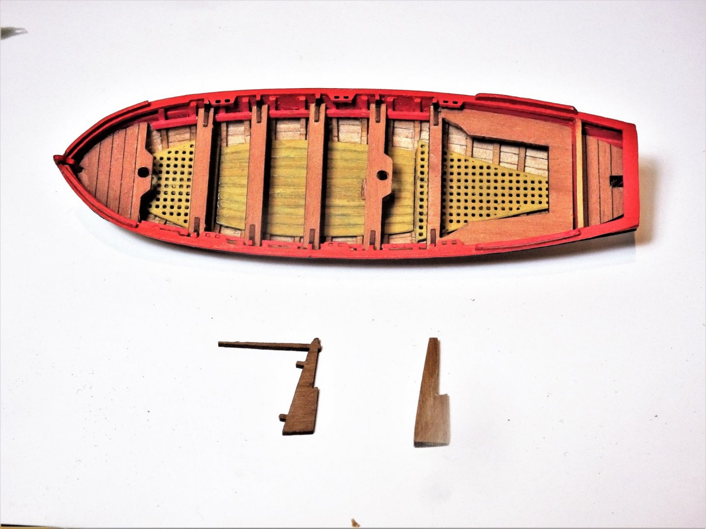
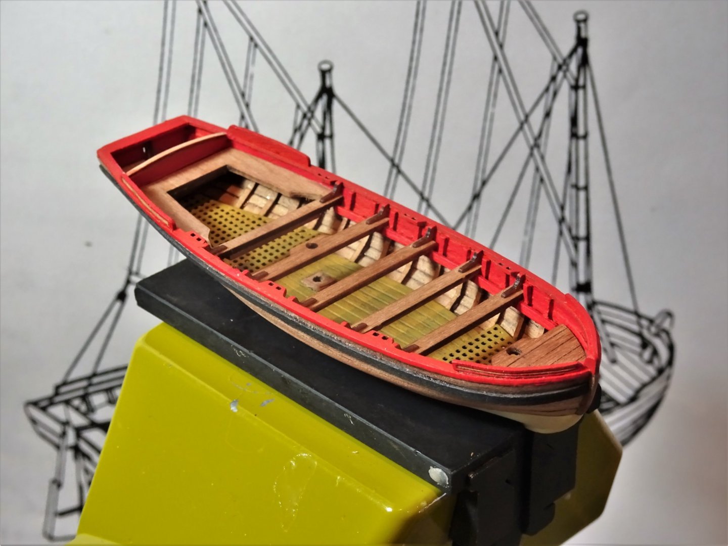
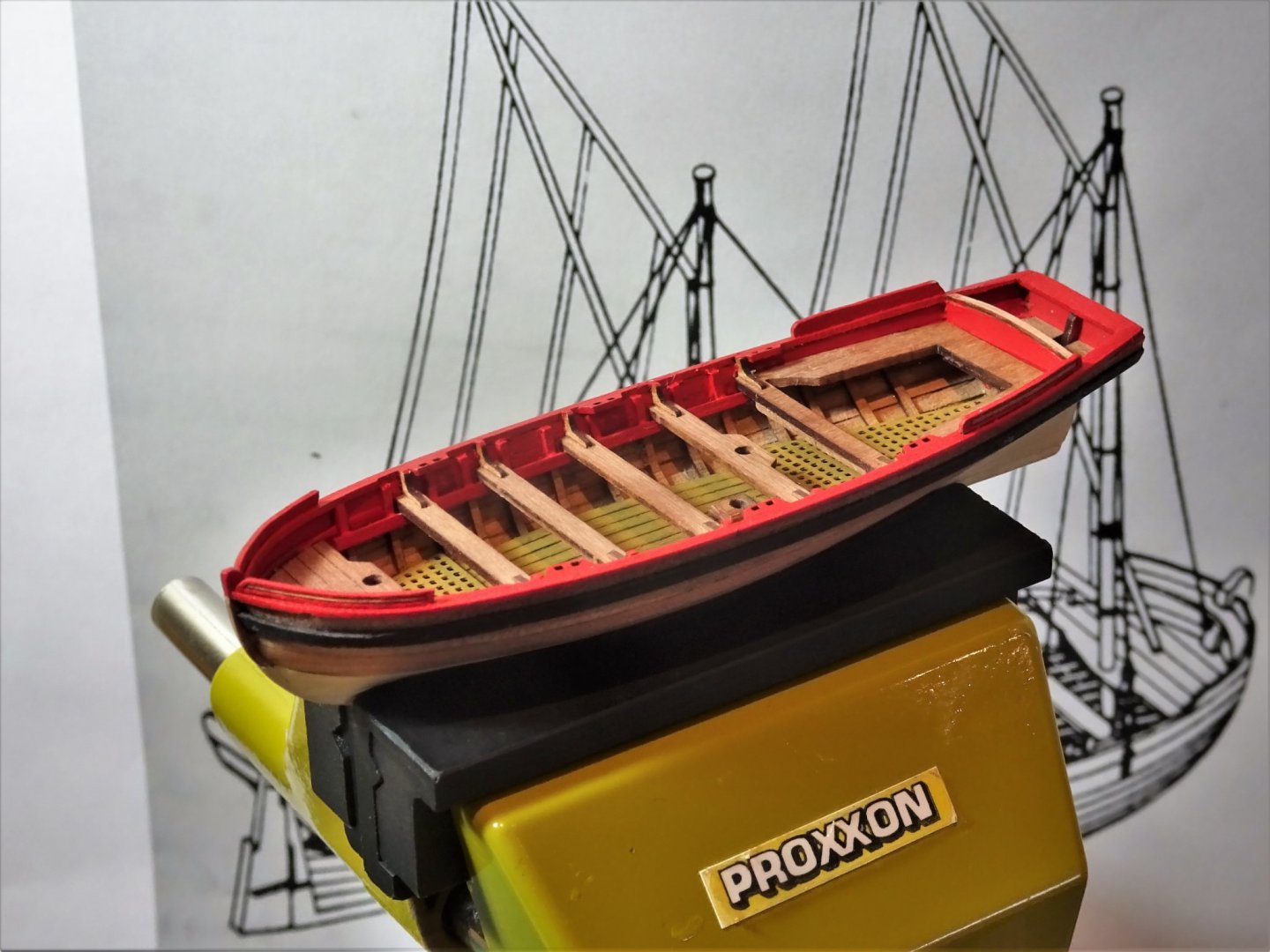
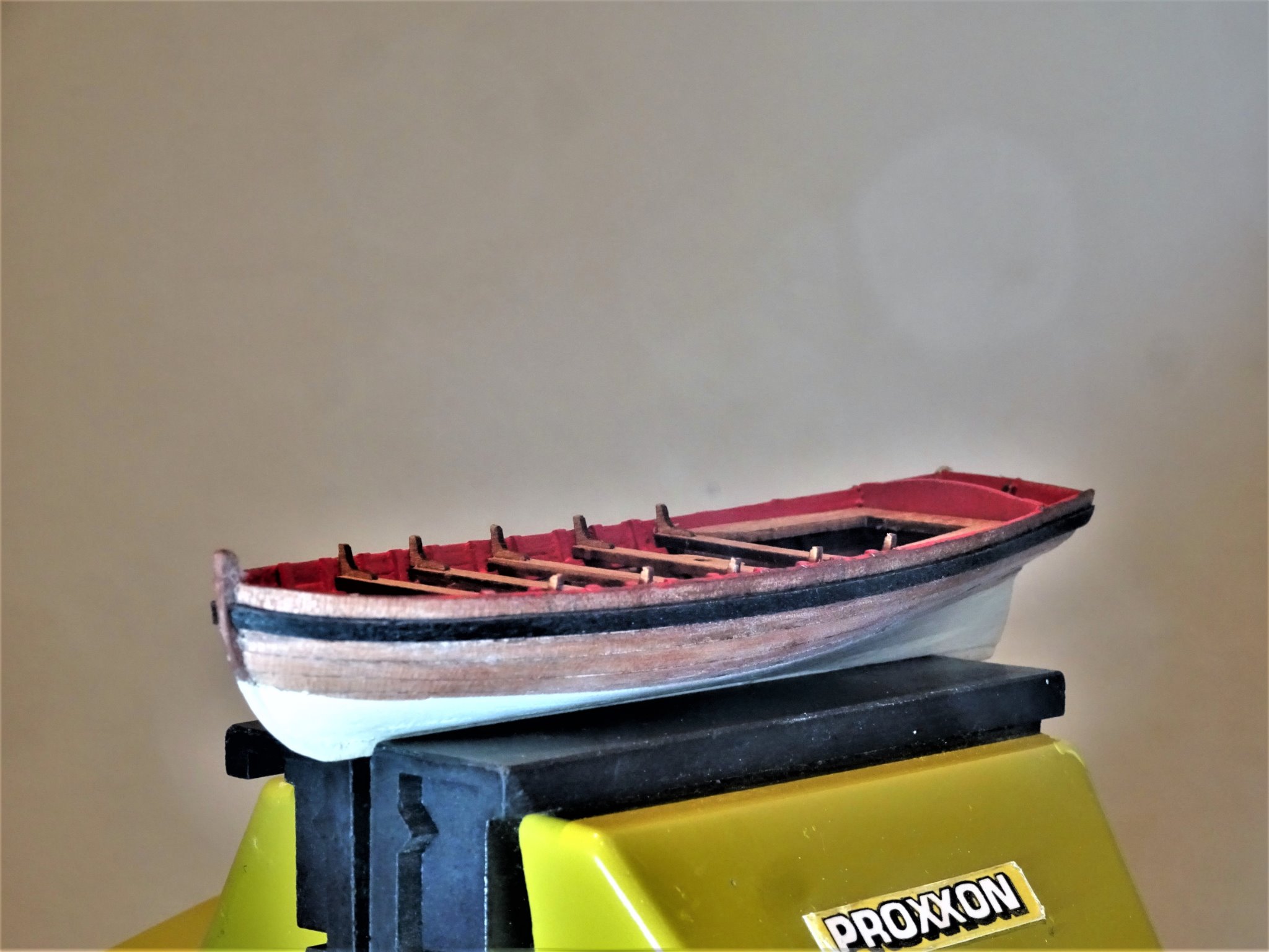
Post Fifteen Fitting the rudder. As with my approach to the cutter build I have discarded the provided rudder with its brass etched facings in favour of a new rudder cut from Pearwood scrap. 00397 The thickness matches the etched ‘sandwiched’ original but the length is left slightly longer to give me more leeway in the positioning of the tiller. 00421(2) On the model a small eyebolt with a fine brass pin silver soldered into it made for the pintles, and eyebolts for the gudgeons. The lower pintle was fitted to the sternpost, it was longer than usual for ease of location. The upper one was fitted to the rudder. 0412 This arrangement was to facilitate ease of removal and re hanging whilst the boat was in the water. 0402 I think it’s time for a general tidy-up.🙄 0443(2) 0426(2) 0427(2) 0439(2) 0440(2) I still need to treat the Pearwood hull with wipe-on-poly and add the rudder straps, but for all practical purposes the basic boat is complete. Before I proceed further, I will attend to the iron hull fittings for the rigging. B.E. 10/02/21


.thumb.JPG.2dddffc0b6097606ab65069142bcf8de.JPG)
.thumb.JPG.a5c5006760868b94ec9c42541b36328b.JPG)
.thumb.JPG.740e78b43a11a0c6578f31074342fe3f.JPG)
.thumb.JPG.c97532d0cf03addecd63a03db60d1946.JPG)
.thumb.JPG.5734209da46c0aec8911a915d2fdc467.JPG)
.thumb.JPG.ed68c50794194a172195e4a0fac67456.JPG)
- 70 replies
-
- 9
-
-
- 22ft Yawl
- Vanguard Models
- (and 2 more)
-
She's looking very smart Eric with some nice little tweaks and additions, which all add to the build experience. Your Pinnace is morphing into a Barge before our very eyes. 😉 B.E.
- 123 replies
-
- 3
-
-
- Model Shipways
- Pinnace
- (and 1 more)
-
Beautiful work Rusty, your wood match of the non wood parts looks spot on, a very fine build. 👍 B.E.
- 201 replies
-
- 2
-
-
- Duchess of Kingston
- Vanguard Models
- (and 1 more)
-
Post Fourteen Gunwales The Gunwales are laser cut Pearwood and what a delight they are. Finely detailed and incorporating the thole pin sockets they were a good fit along the sheer line. I had left the thwart brackets long to butt the gunwale against and they perfectly position the strips. I use ca spots to secure them to the boat. Atop the Gunwales are fitted the Splash boards at the bow and stern. Altho’ these are a mere 1.5mm deep Chris has managed to include an engraved pattern on the face to reflect the mouldings that often featured on these parts. The splash boards require a little bending to suit the run of the Gunwale particularly at the bow, and then they were pva’d into place. 00389 00390 Painting these intricate areas is a time-consuming exercise; lay a coat down, photo it, recoil in horror at the macro, sand using thin sanding sticks and fine paper, repeat the exercise. 😉 Great value for money these bijou offerings from Chris, where else can you get endless hours of pleasure and pain for a mere Twenty-five quid. 🙂 Lovin’ this kit. 👍 B.E. 08/02/21
- 70 replies
-
- 14
-
-
- 22ft Yawl
- Vanguard Models
- (and 2 more)
-
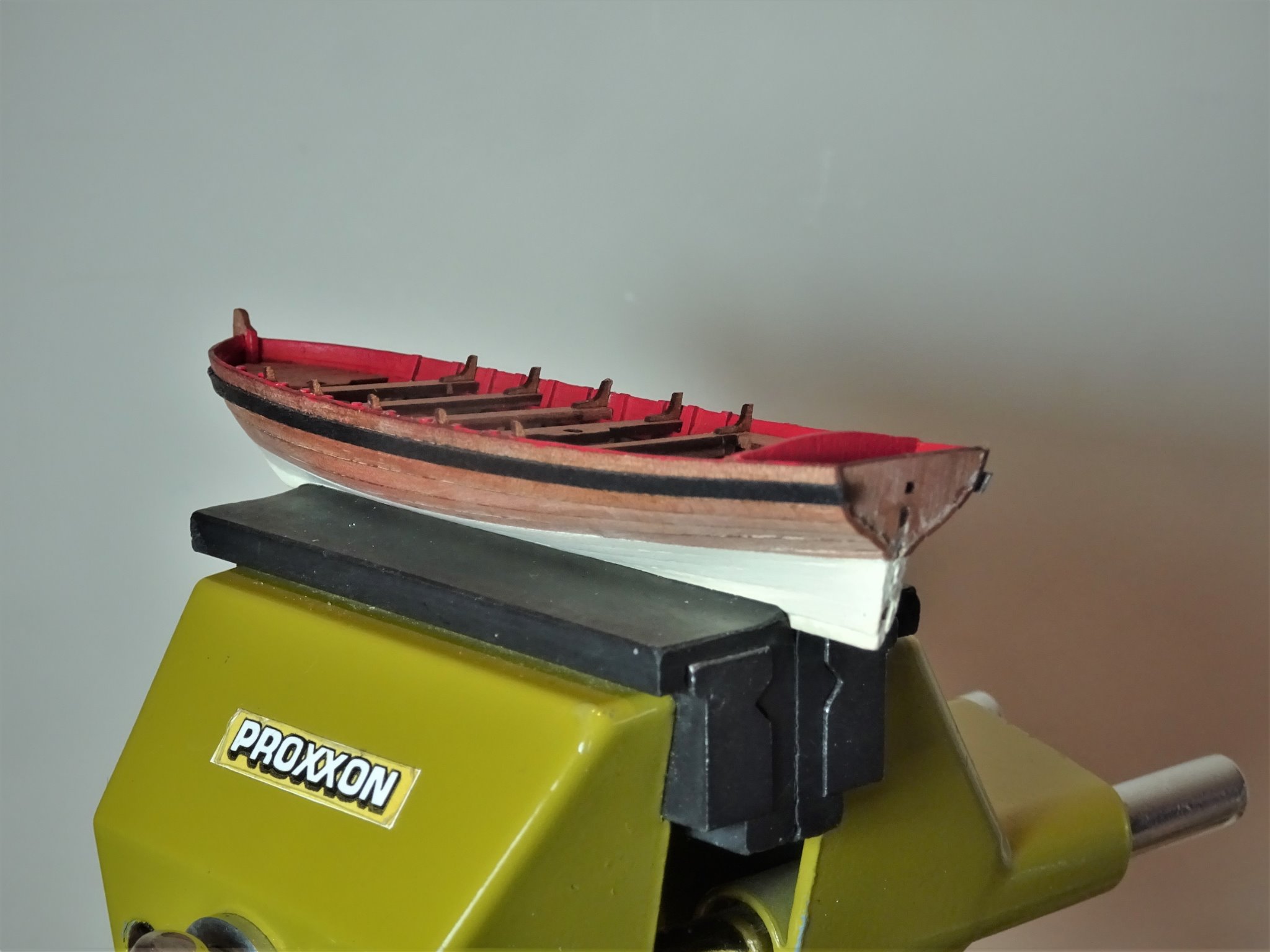
Post Thirteen Inboard works Yawls were fitted for sailing and it has taken my fancy to mast and rig her mainly because I have the reference source (Pandora AotS book) and not many models show the set up on these small boats. None of this aspect of the build is part of the kit. Before I can glue the thwarts in place, I need to fix the position of the tabernacle for the Main mast heel and test the fit of the masts. 00334 00332 00336 The dimensions of the masts and yards are given in the AotS book Pandora. 00339 Only need the heel fitting at this stage, the upper taper to 1.5mm at the peak can be done later. A little speedier progress now, the thwarts are glued into place, the brackets added. 00347 00348 00357 I have decided to fit the wales at this point. 00353 These are pre bent to assist ease of fitting. 00374 I used tiny spots of ca to fix the wales. 00360 00362 I now need to add the Gunwales and think about the rigging fittings. B.E. 07/02/21


.thumb.JPG.bddd07bc9b9261b5c8fd5ac4f7106c8c.JPG)


- 70 replies
-
- 8
-
-
- 22ft Yawl
- Vanguard Models
- (and 2 more)
-
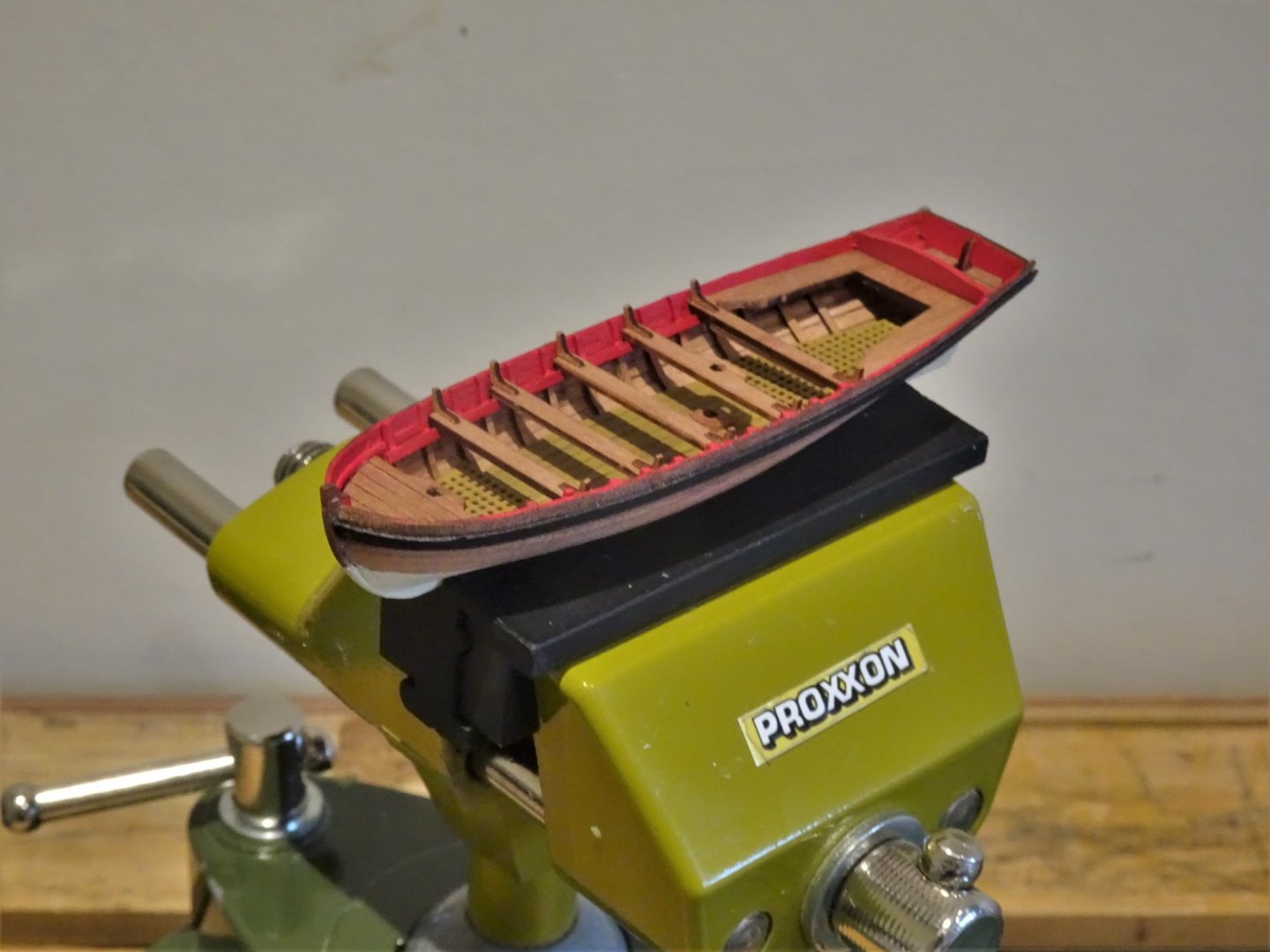
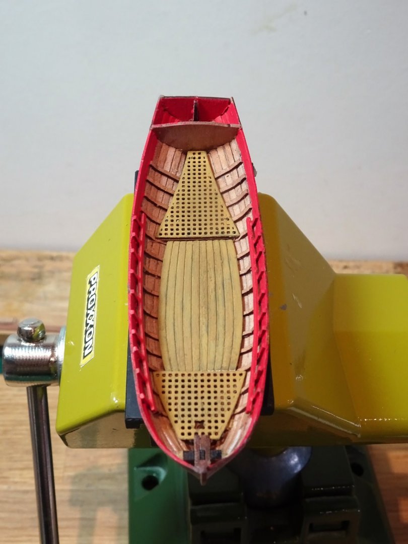
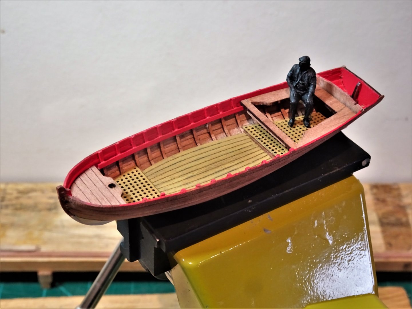
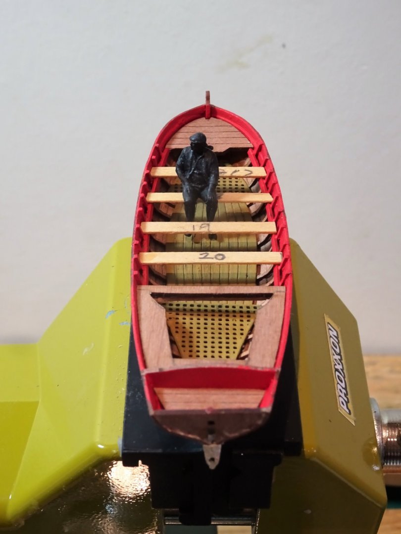
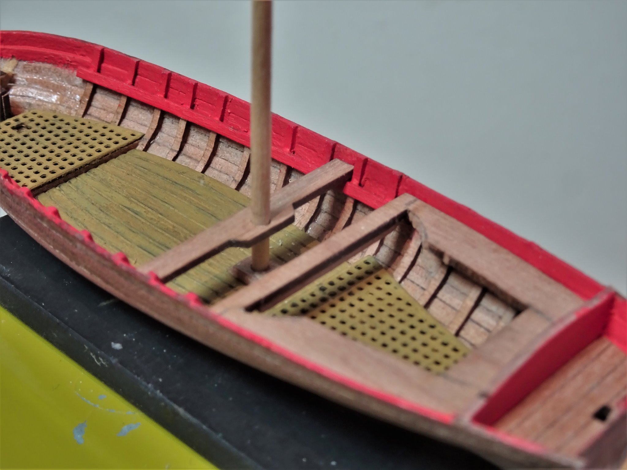
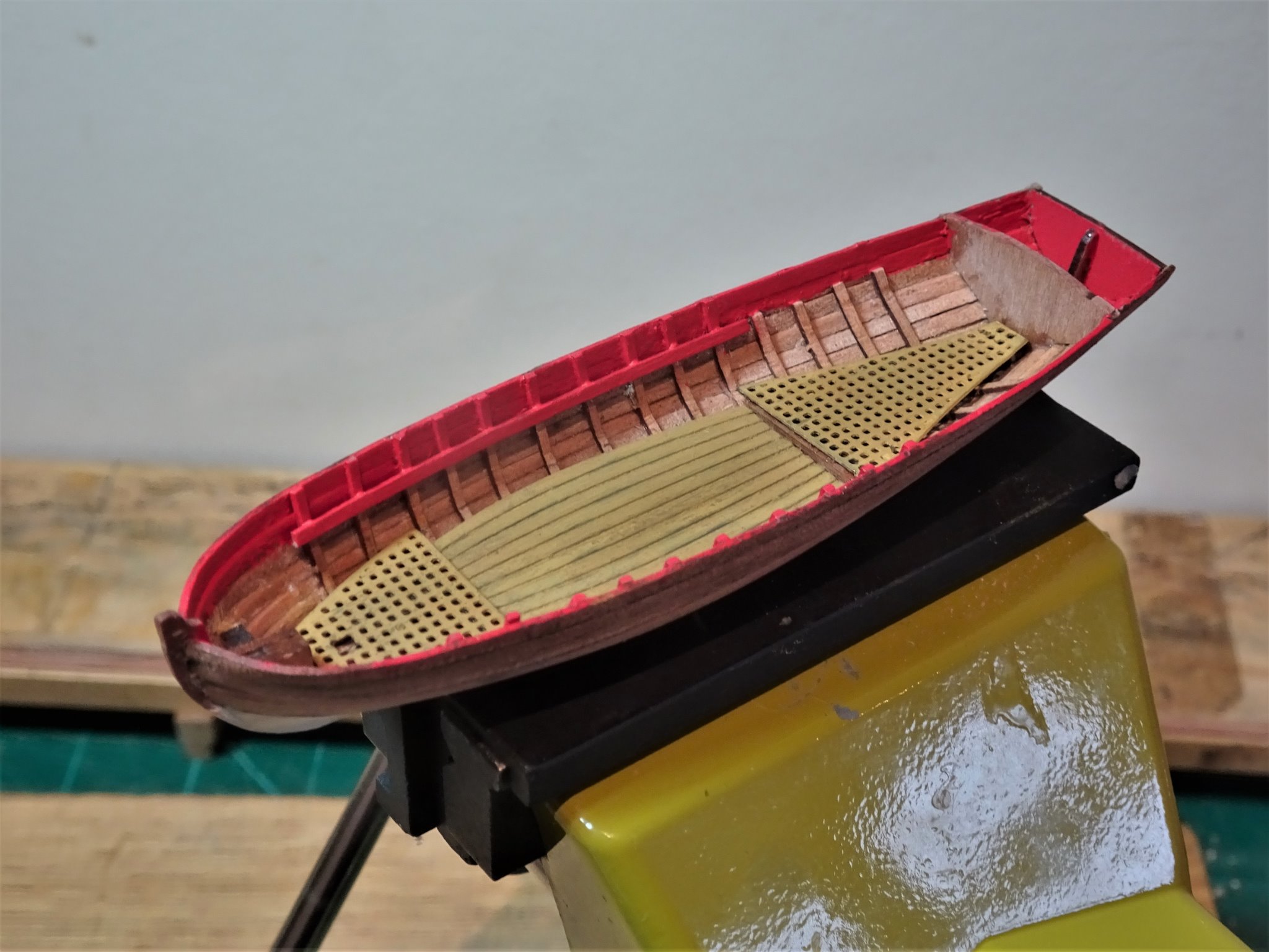
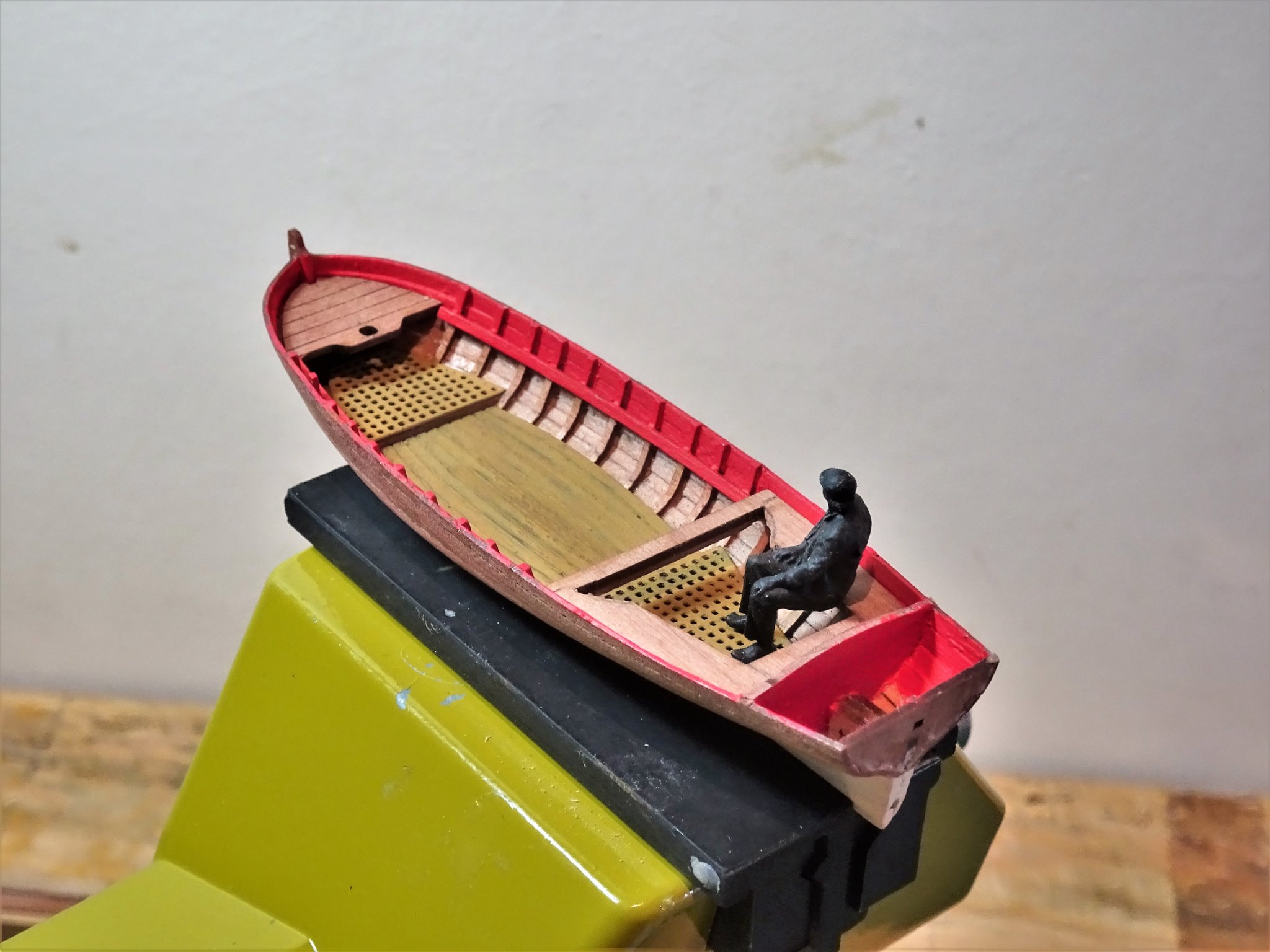
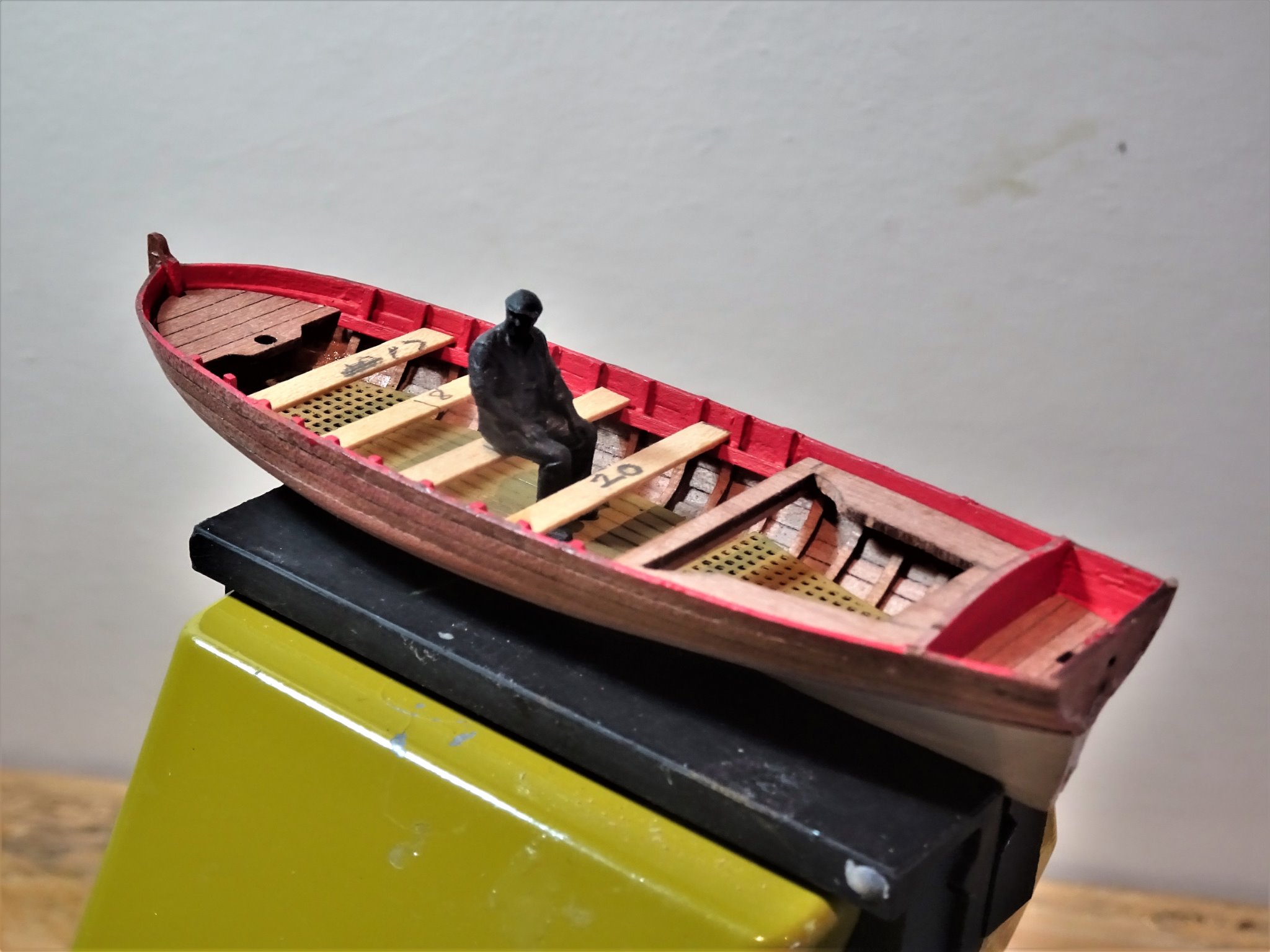
Post Twelve Making wood out of brass. I did think about replacing the decking board etch with planks but decided to keep the etched version as it matched the bow and stern sheet gratings. After a thorough cleaning with soapy water, scrubbing, and sanding, followed by an acid dip, I chemically blackened the parts which will give a better surface for painting. Having given the etch a base coat of Humbrol 93 I applied a thin streaky coat of Humbrol 94, followed by a dry bushing of sand yellow weathering powder. 00315 Between the boards I ran diluted black/grey water-based paint, and gave the whole thing a wash of dark brown weathering powder immediately wiped off. 00317 I spent a fair bit of time fiddling with the gratings / boards to get a fit I was happy with. The gratings should fit above the boards, and I added support timbers where the gratings meet the boards. 00322 I also used my Muirneag Skipper to check the relative heights of the stern sheets and grating. 00323 It is reassuring to note that the scale figure confirms the correct height of the internal fittings. Well done Chris 👍 00329 00330 These are just the temporary thwarts used to check the positioning. As can be seen I have decided to part paint the Yawl as I quite liked the combination of colour contrasting with the Pear-wood natural finish. 00291 I used Light Ivory (Admiralty Paints) for the lower hull, and Flat Red (Vallejo) for the Gunwales and internal planking down to the stringer line. The remainder will be the natural Pearwood finish enhanced with wipe-on-poly. The kit suggests a more simplified approach of painting the bottom white up to the wale which is a perfectly acceptable scheme, particularly for later period boats, but I prefer to have the contrast of the natural wood. 00296 The waterline was gauged by eye and by reference to bow and stern points on a yawl plan. Still a way to go with the internal fittings. B.E. 06/02/21


- 70 replies
-
- 12
-
-
- 22ft Yawl
- Vanguard Models
- (and 2 more)
-
Well done Tim, a fine looking build, you should be well pleased. 👍 B.E.
- 436 replies
-
- 2
-
-
- vanguard models
- alert
- (and 1 more)
-
An almost impossible question to answer Erik, as it’s all about perception. For what it is worth, your Hull is pretty pristine, so weathering the sails may present a discord. The other consideration is that once started there’s no going back, a tricky decision. Good luck B.E.
- 222 replies
-
- 2
-
-
- First Build
- Lady Isabella
- (and 2 more)
-
That knob is known as the button, and the whole fitting on the end of the gun as the cascable. Before the advent of the Breeching ring atop the cascable on Blomefield pattern guns, the rope was simply looped around the button, or spliced around the button. No knots as such are involved. B.E.
-
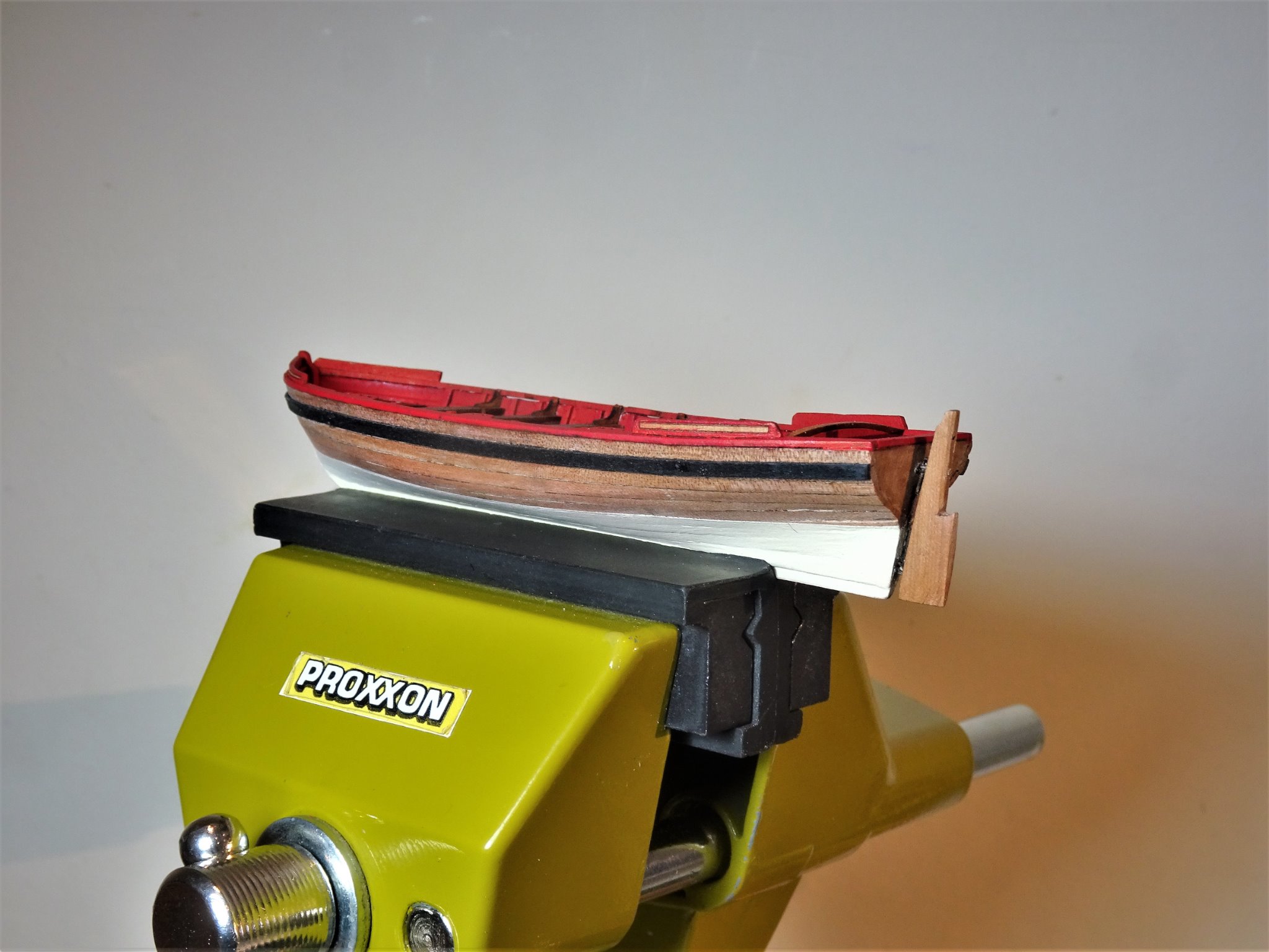
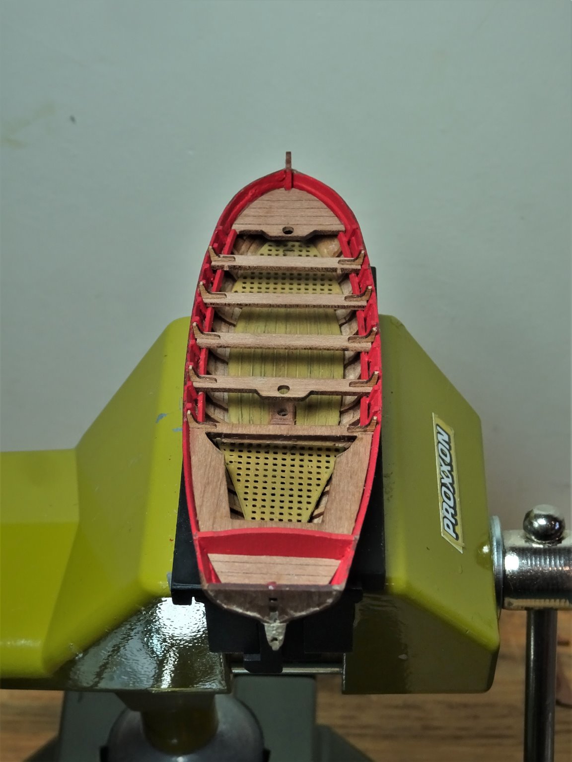
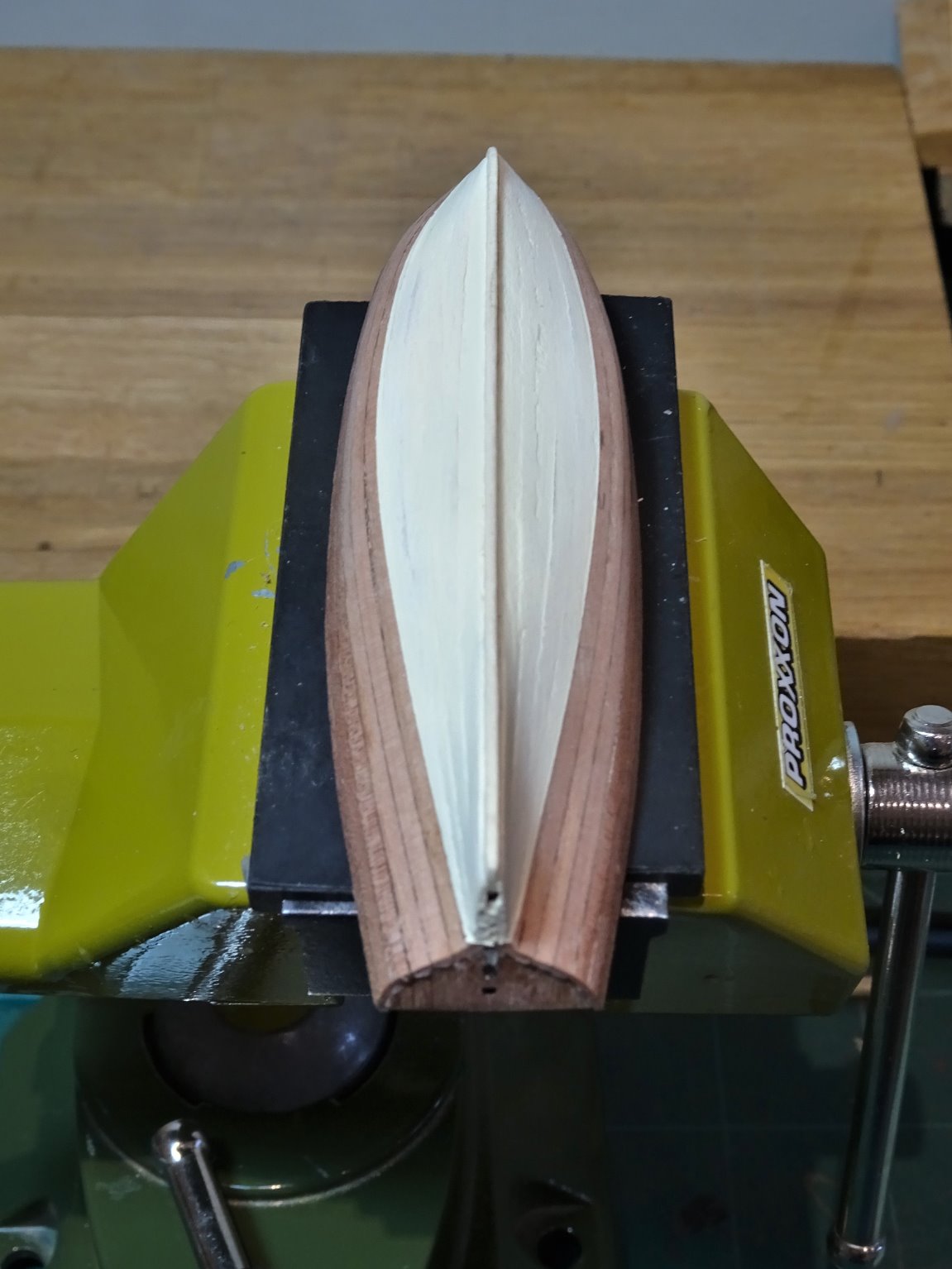
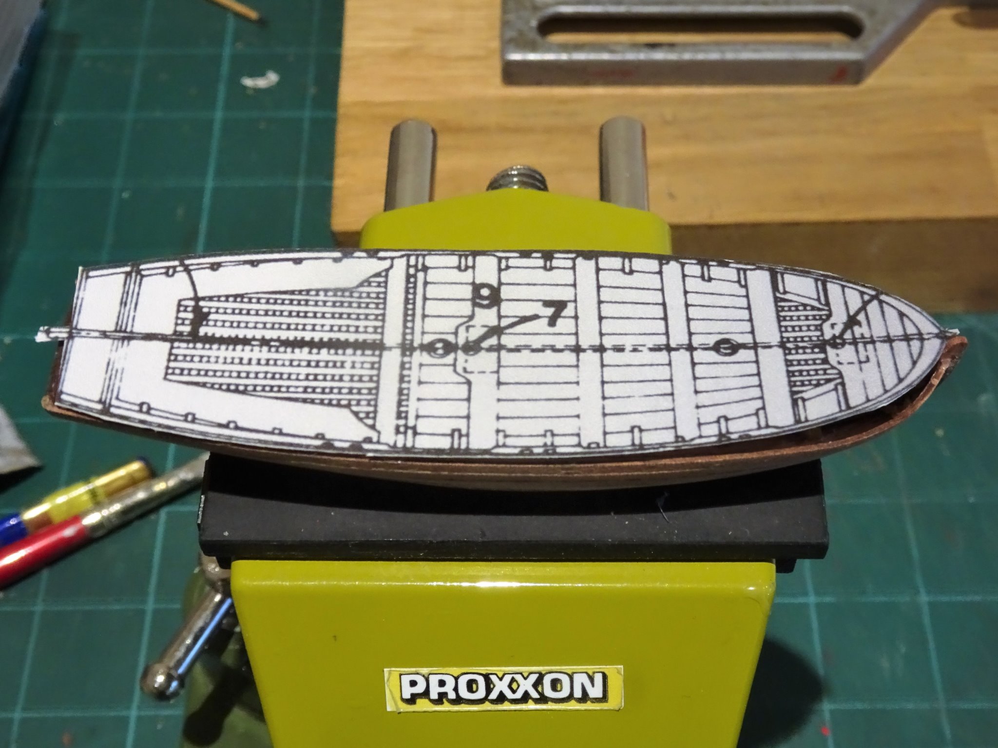
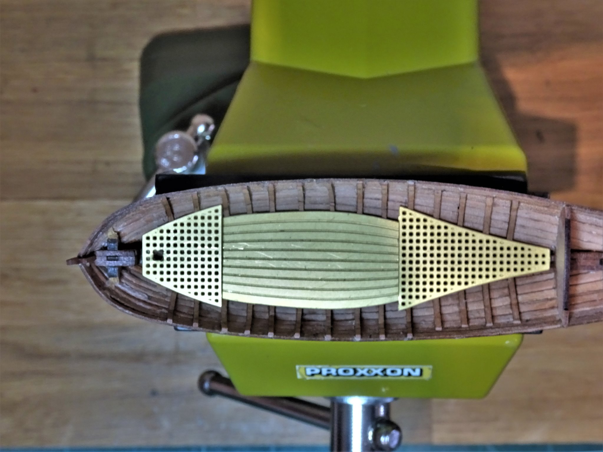
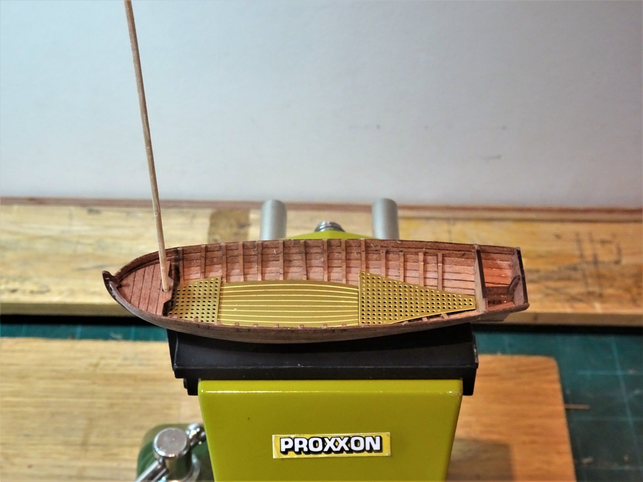
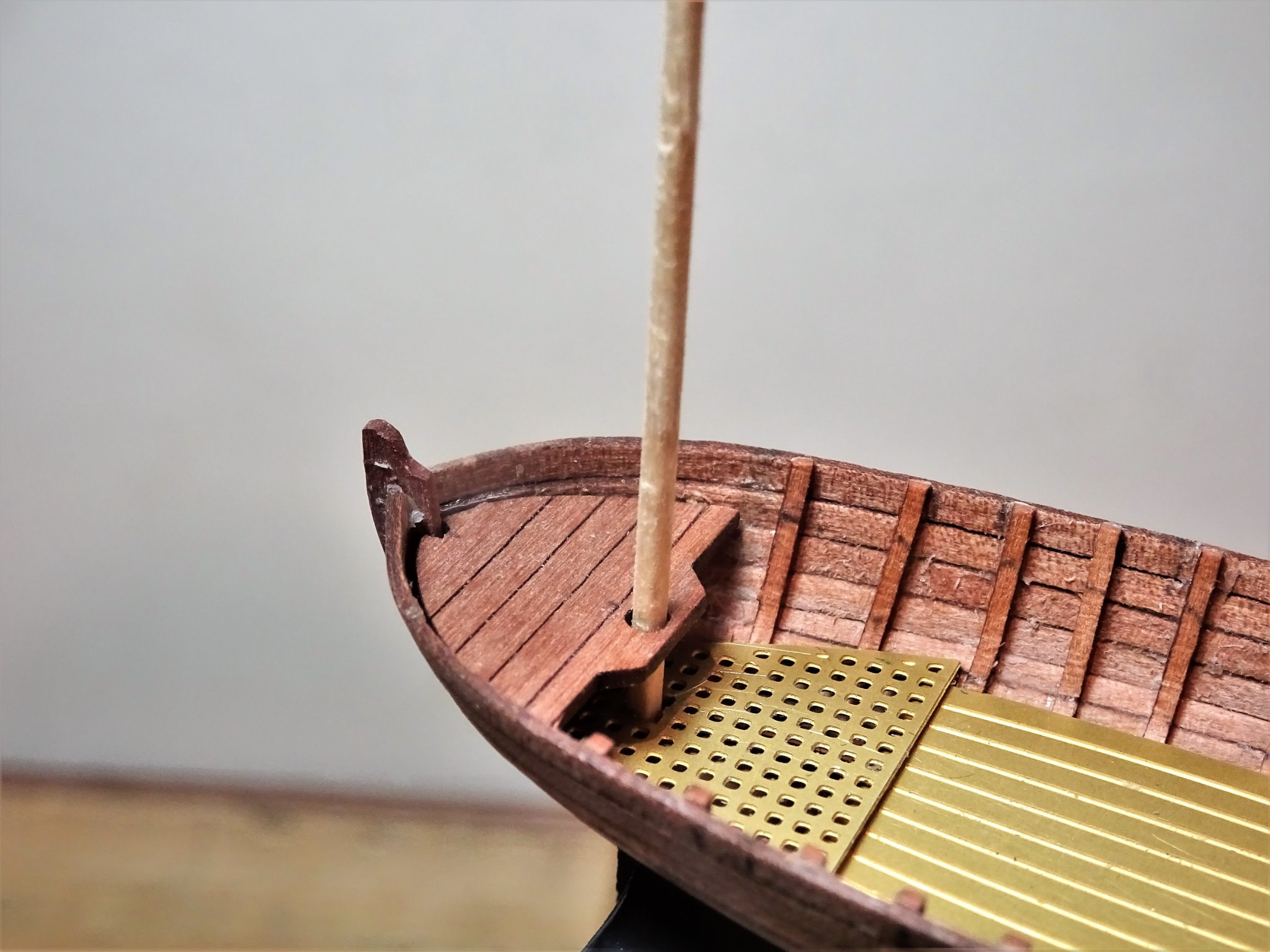
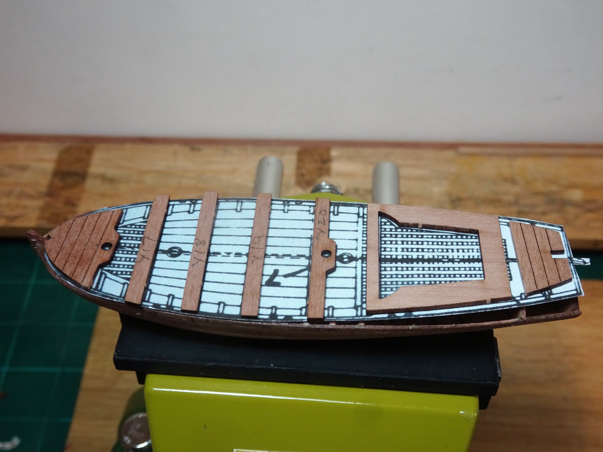
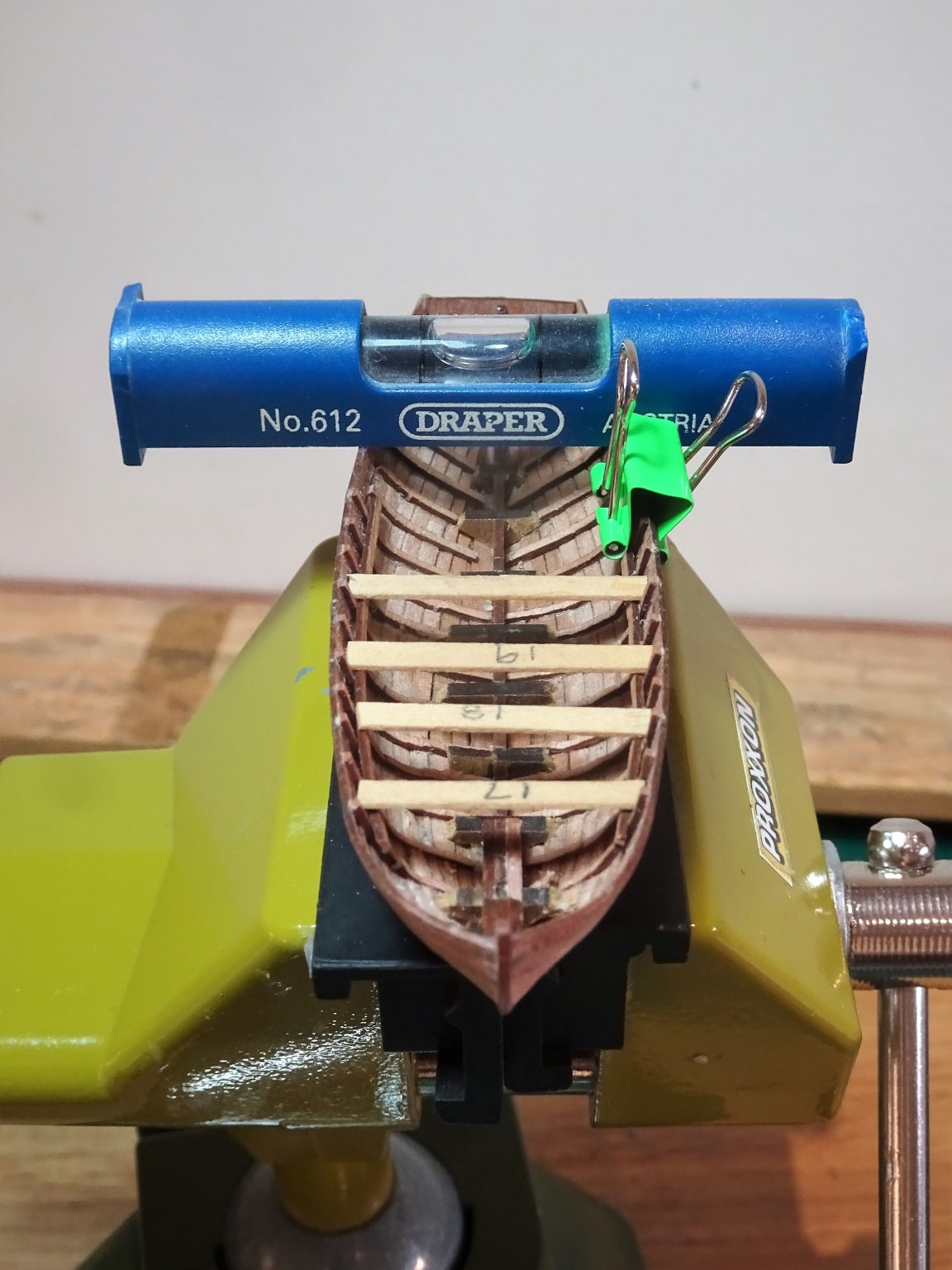
Thank you Jason and Richard. @ Richard - the frames are the kit provided stuff 1mm x 0.7mm, it bent quite easily with dipping in water. The stuff is a lot finer than supplied with the now withdrawn original cutter kit. POST 11 Internal fittings With the ribs installed I now need to work out the fit of the boards and gratings. The lower parts of the ribs need paring away by degrees to allow the brass etched gratings and boards to sit properly down. 00253 A square has been cut out of the bow grating to take the heel of the Foremast. 00259 A temporary mast fitted thro’ the bow deck and grating. I am using the AOTS Pandora book as my guide which has a 22’ Yawl as part of the boat allocation. 00225 I re-scaled the drawing to fit the hull at 1:64 and it is a pretty good fit. 00255 I did reduce the length of the Bow deck by removing the plank adjacent to the mast fitting which allowed for better thwart spacing which were otherwise a good match. 00262 Next up for fitting are the stringers which support the thwarts. These are fitted 3mm below the rail which accords with the 1:128 scale drawing in the Pandora book. A simple gauge was fashioned to check the height as I fit the stringers. 00264 The Proxxon vice allows me to level the boat and with one stringer attached the second is applied, and temporary thwarts used to sight the level across the boat. Off-level thwarts can spoil the look of a boat. I next need to work on making the etched gratings and boards resemble wood. B.E. 04/02/21


- 70 replies
-
- 8
-
-
- 22ft Yawl
- Vanguard Models
- (and 2 more)
-
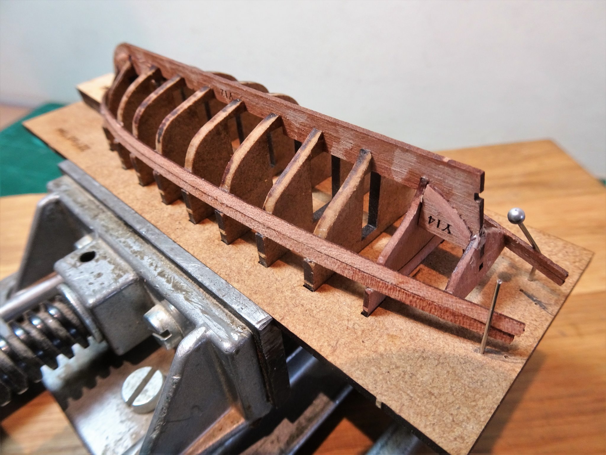
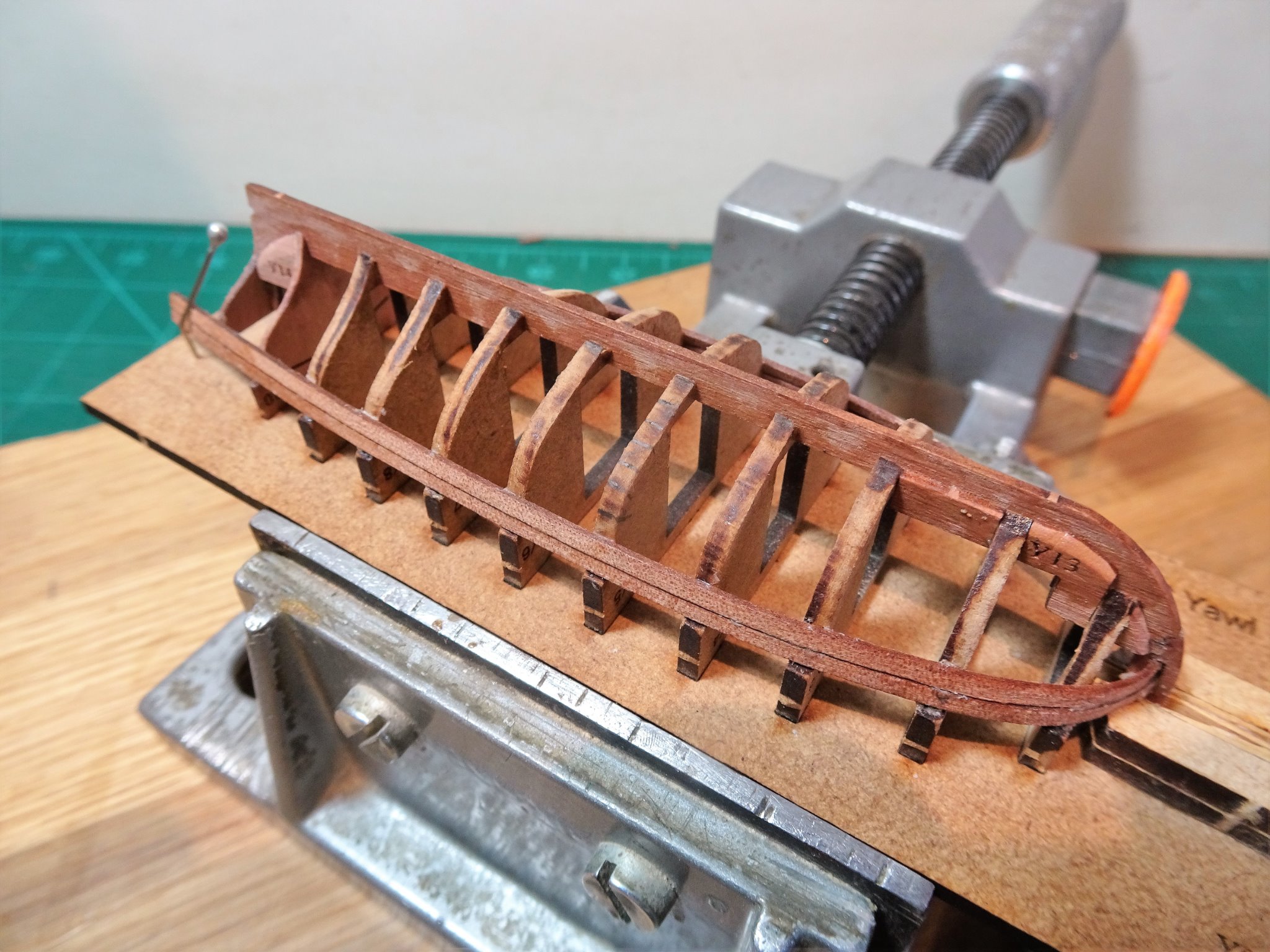
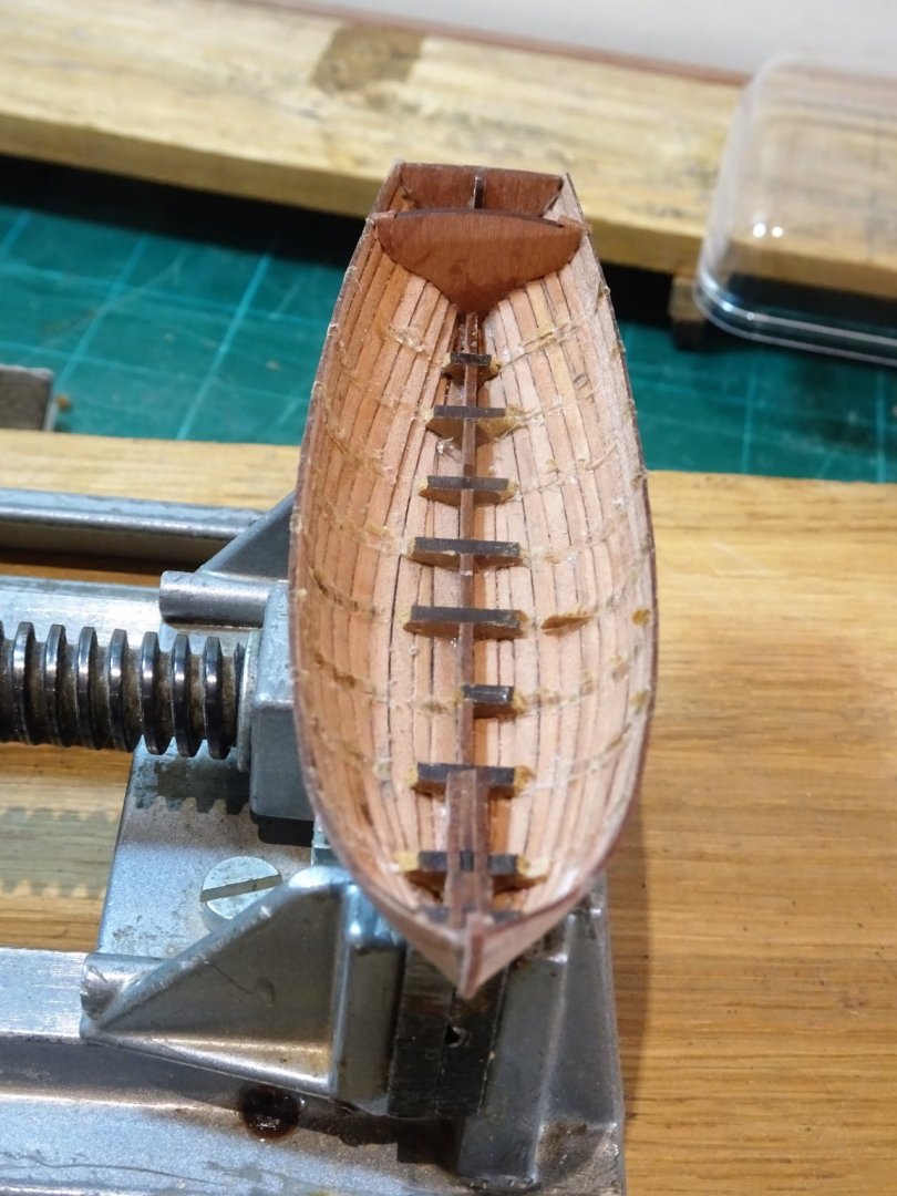
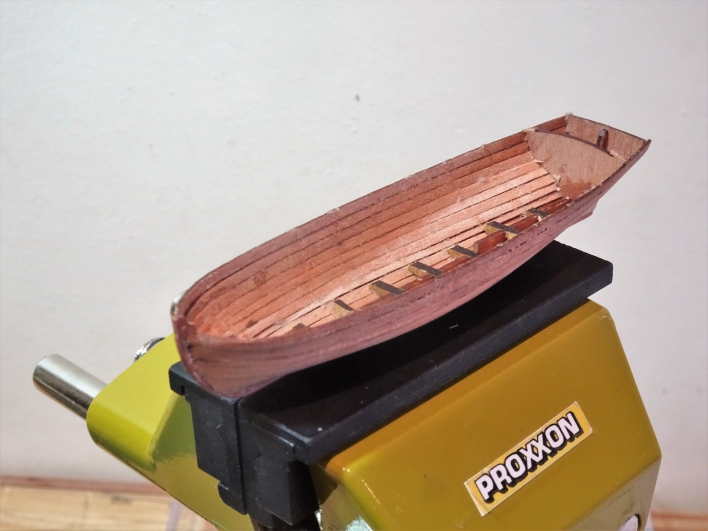
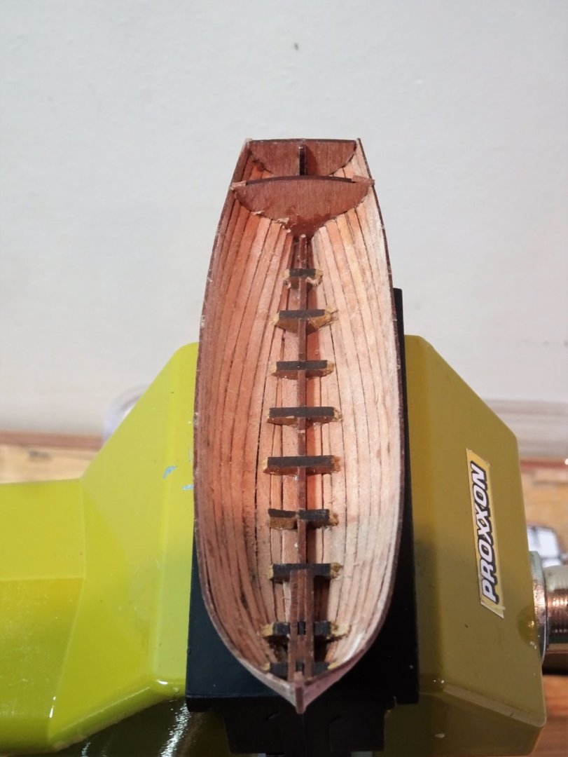
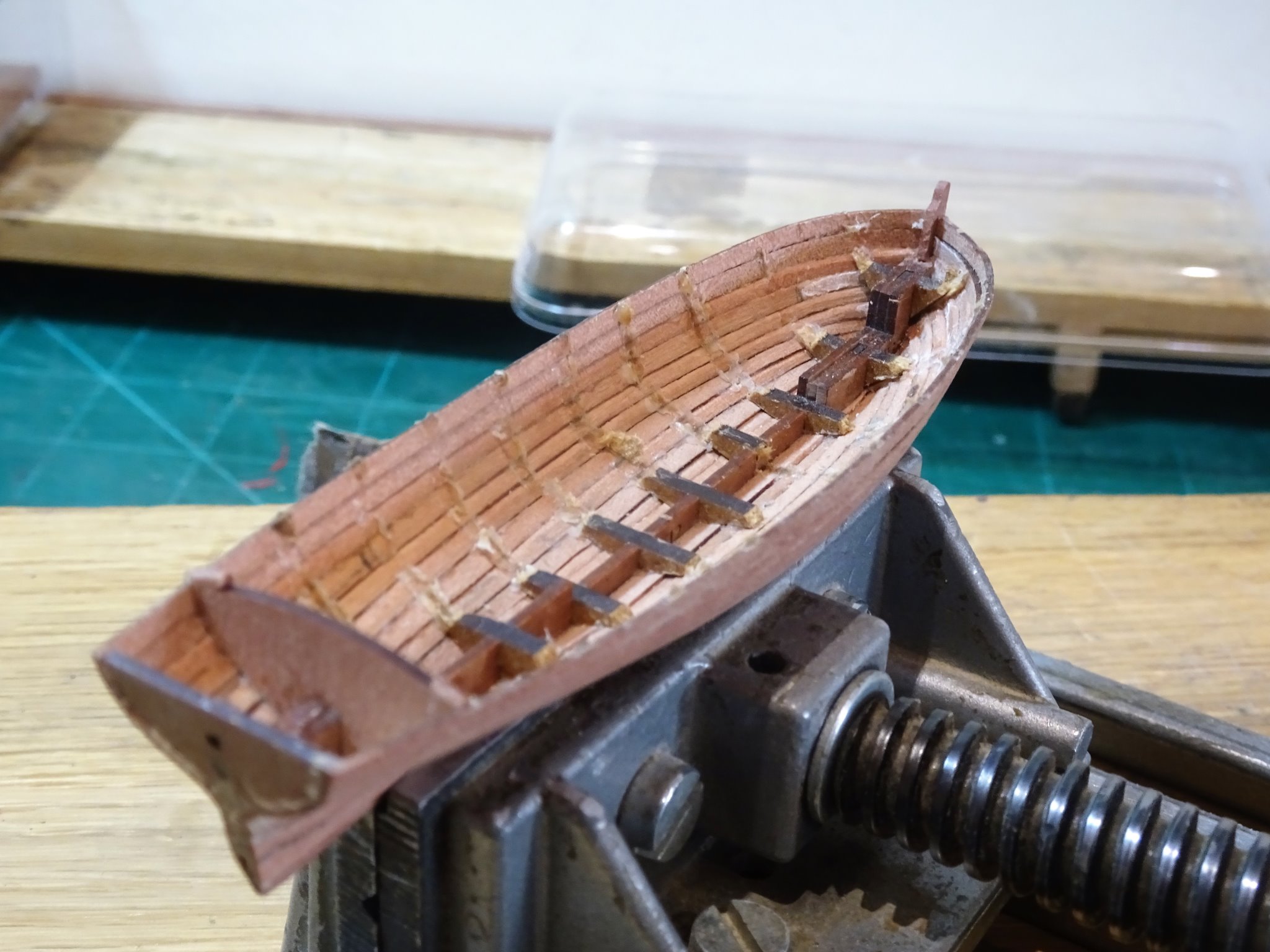
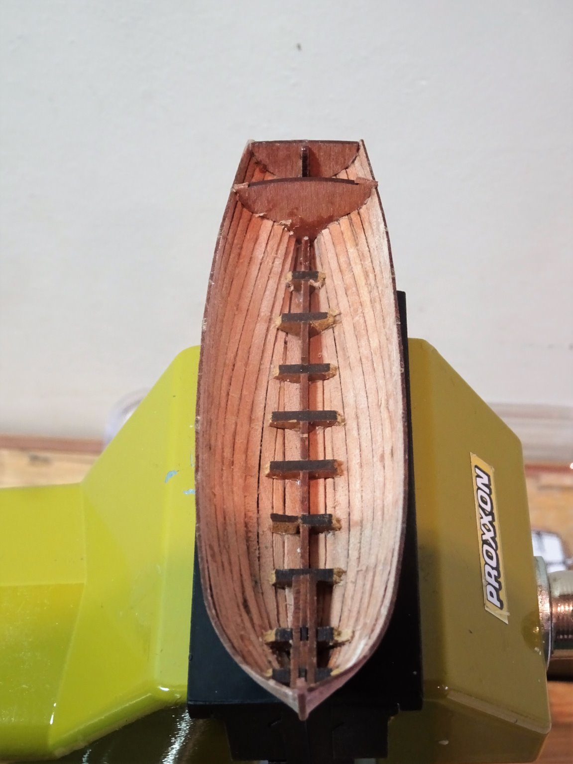
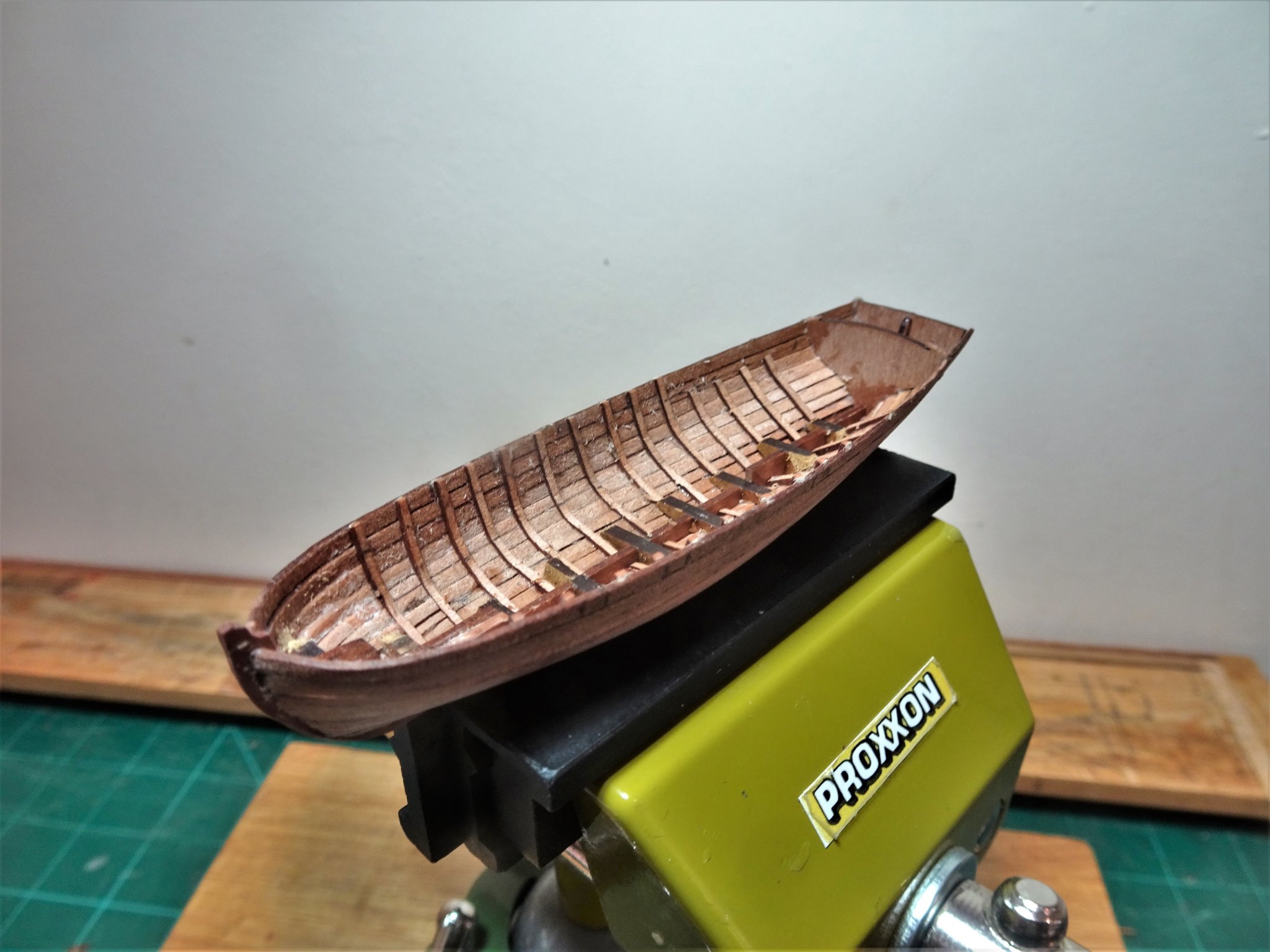
Post Ten Released from the board To fill any minor gaps I use diluted pva and Pearwood dust, it’s then just a case of sanding until a finish is obtained. Snipped across the central bar the bulkheads came away without trouble with a simple twist with pliers. 00216 With the bulkheads released, the internal planking can be fully assessed. 00219 Only a little ca staining at the bow end which will hopefully be covered by the fore deck. 00231 Use of pva for the majority of the glue work bore fruit in that cleaning up of the internal boarding only required a wetted paintbrush and a micro chisel, the excess glue just came away. 00230 The hull is very delicate, and a light touch is still very much required, take care not to apply lateral pressure to the hull sides. 00247 The next stage is to add the internal frames; the blurb simply says glue short lengths, inside the hull around 5mm to 6mm spacing – as shown in photo 23. 00248 Once the ribs are in place the hull becomes much stronger. As with the planking I seem to have come up short with the ribs(Y28) but I used one of the seat support strips (Y27) for the shorter ribs, which were sufficient at a pinch. The kit has four internal seat support strips but only two are required, I think the kit would benefit from a couple of extra rib strips. B.E. 03/02/21


- 70 replies
-
- 6
-
-
- 22ft Yawl
- Vanguard Models
- (and 2 more)
-
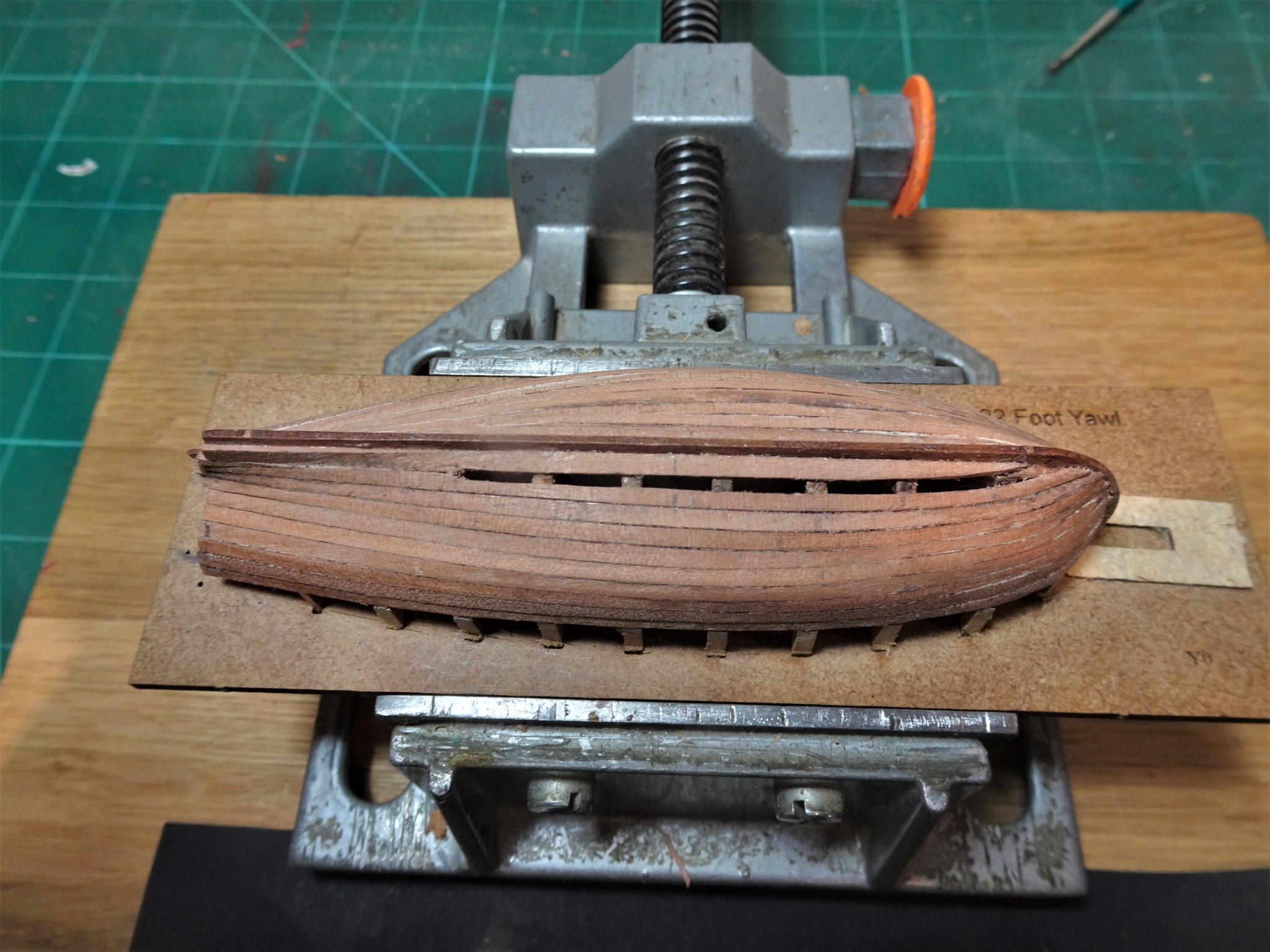
Post Nine Completion of planking 00190 The final spiled planks butt against the Garboard. 00207 One more plank to go. 00205(2) This is a tricky plank to shape and I tweaked the Garboard to get a reasonable fit. 00208 00209 00210 A relief to complete the planking but a fair degree of fettlin’ is required before she’s released from the building board. 0211(2) This is all that is left of the planking material, a close-run thing! blurb 34 indicates - fitting the wales (from the planking sheet). On the planking sheet the wales are not separately identified, so they must be represented by planking strips, and I have insufficient to make the wales. Not a disaster for me as I am using Ebony strip for the wales, but I think additional strips in the kit are needed, to give us fumble fingers a little more leeway.🤞 B.E. 01/02/21
.thumb.JPG.726f395d1f9d4f60c649f502b92dbb20.JPG)


.thumb.JPG.cee0a17b44f08f9a2073d56776da8862.JPG)
- 70 replies
-
- 7
-
-
- 22ft Yawl
- Vanguard Models
- (and 2 more)
-
Thanks Chris, I haven’t looked at the Pandora book for a long time, but there it is large as life in full colour. I’m glad I didn’t have to tackle that on my Pegasus.🙄 In the TFFM in relation to Sixth rates David Antscherl comments: There is only space for three strakes in the width of the wale on a sixth rate. The uppermost strake is worked parallel, and the lower two are worked top and butt. In larger ships these strakes were hooked, but in a sixth rate this does not appear to be the case. His reference is the planking elevation, topsides of Hornet, dated 1776. Still it is all academic and you have done a very fine job with Sphinx. Ps Leading me back to Pandora reveals a 22’ Yawl, spritsail rigged, looks like the yawl build will take a bit longer.🙂 Regards, B.E.
-
Thank you Jan, that is something I've not seen before. I wonder if they used a half scarph that wasn't carried through to the external face. I note that the expansion plans were dated 1808 which post dates the other plans by some years. Personally I think the arrangement on the model looks a little too fussy, and although I fitted top and butt wales on my Pegasus build I don't think I could have managed those additional features even if authentic. B.E.
-
Out of curiosity Chris, what did you base the Top and Butt wale planking on; I don't think I have seen that additional scarph joint arrangement on the legs. B.E.
-
Well done Jason, she looks great, and you should be well pleased. 👍 Thank you for your kind references to my Pegasus build. Regards, B.E.
- 800 replies
-
- 2
-
-
- snake
- caldercraft
- (and 1 more)
-
One thing to think about Erik is that with the reef points threaded through the sail they will invariably stick out needing pva to persuade them to hang down naturally. To do this there is a greater risk of marking the sail with glue, which will be difficult to remove. I opted for the less authentic, but hard to spot the difference, method of gluing pre knotted reef points to the sail each side which obviates the issue. I wish you luck with this tiresome business, whichever method you choose. B.E.
- 222 replies
-
- 2
-
-
- First Build
- Lady Isabella
- (and 2 more)
-
Blind leading the blind eh Richard.😉 I didn’t paint my cutter, but I guess that Chris/James thought the hull small enough to do it simply by eye. I suppose the waterline could have been included on the line drawing of the boat on it’s chocks, but the example on James’s model is probably close enough. Ps; I have my covid vacc tomorrow afternoon 🙂 B.E.
-
They certainly are a challenge and the fragility is a result of the use of near scale timbers, which do produce the most authentic looking boats I've seen at this scale. B.E.
- 70 replies
-
- 2
-
-
- 22ft Yawl
- Vanguard Models
- (and 2 more)
-
Thanks Bruce, the planks are nominally described as 0.6mm in thickness but mine actually measure 0.7mm + Cheers, B.E.
- 70 replies
-
- 2
-
-
- 22ft Yawl
- Vanguard Models
- (and 2 more)
-
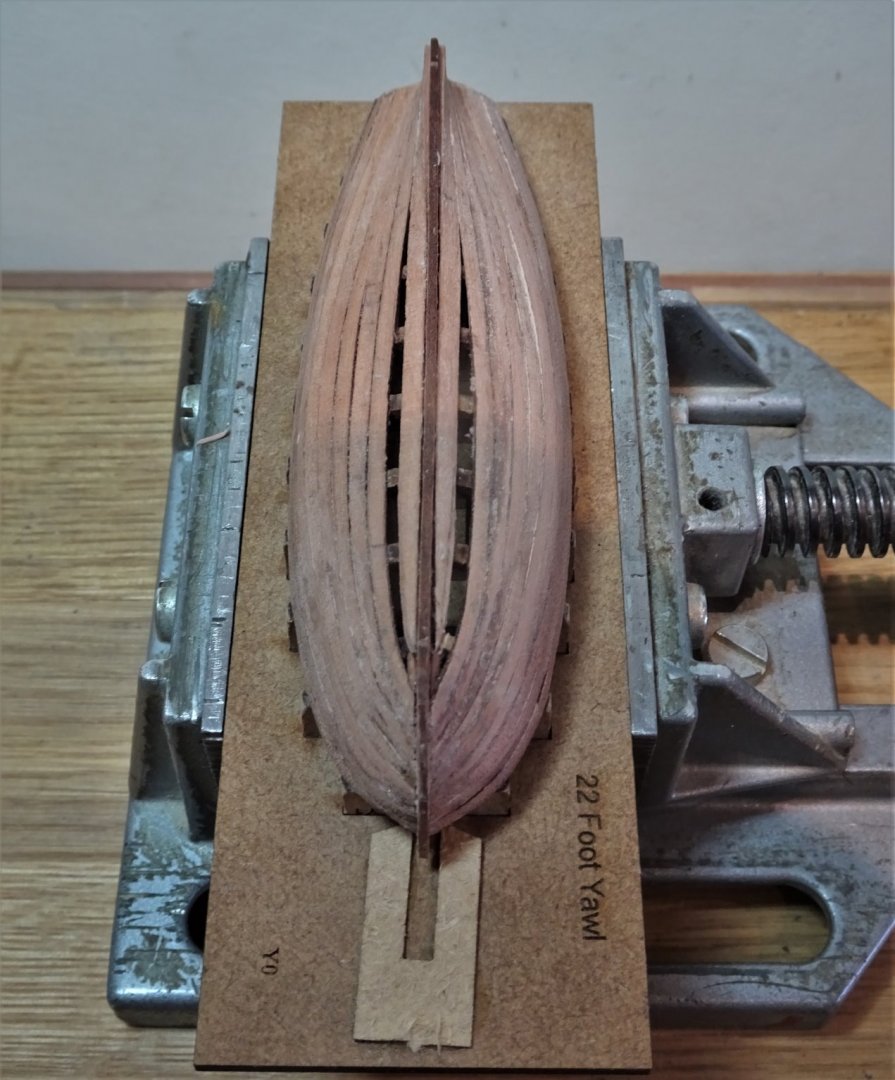
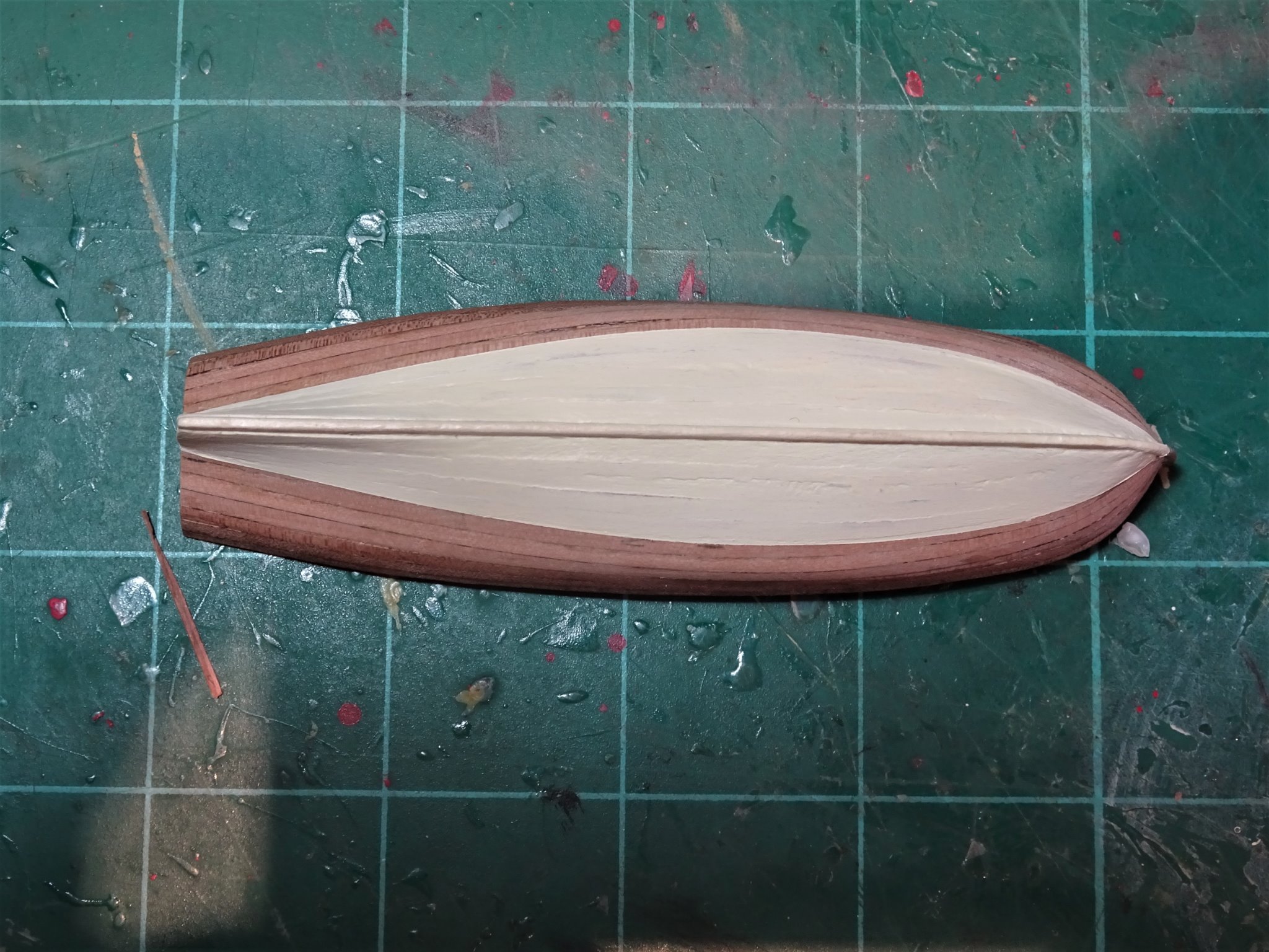
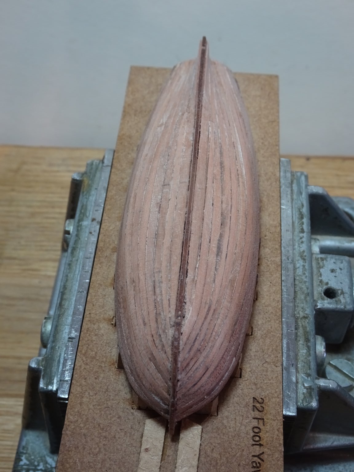
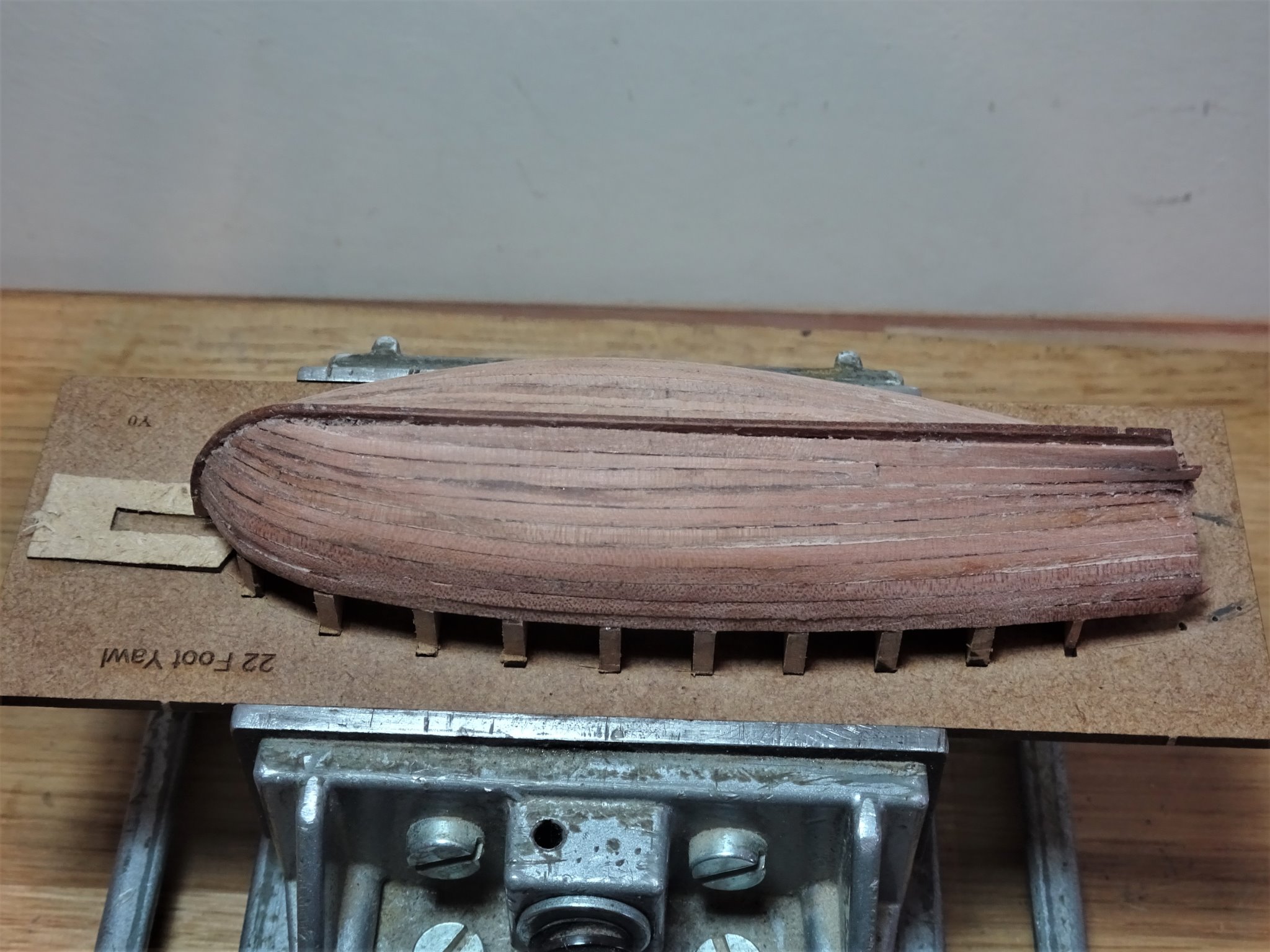
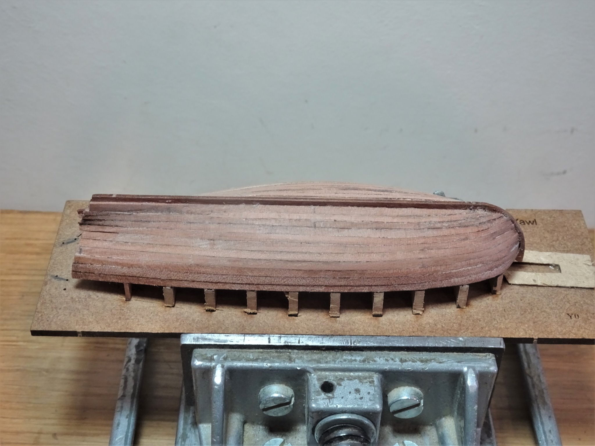
Post Eight …. and more planking As the planking progresses a jig to secure the plank/stem connection proves useful. 00144 A new version is required for each succeeding strake. 00165 Each plank now takes on an individual shape but as the edge bend comes close to the end, I live in fear of breakage of the bow tip. I soak the planks well to reduce the risk. The seventh strake is the last one before I fit the Garboard plank, and the first that I taper toward the stern. At this point the blurb does suggest that the planking now be worked from the keel upwards fitting infil/stealer planks to suit. I have decided to fashion the Garboard Planks from the 0.6mm planking sheet that secures the standard planks. 00176 Useful strips can be cut from the outer frame which allows the Garboard to be cut slightly broader than the planking stock, which is both authentic and hopefully eliminates any awkward thin slices to complete the planking. 00183(2) Planking these bijou models is time consuming, I have now been seven days on the planking and still not completed. In the same time frame I had completed the first planking on the Fifie build. 00182(2) 00181(2) Moving onto the last phase now with only three planks per side left to complete the hull. Three planks will just about do it providing I don’t break any in the shaping process. B.E. 30/01/21

.thumb.JPG.30ecab00c5e09e64b8ce829d43bdce24.JPG)
.thumb.JPG.3f098c43f5a445886cbad000309fa76d.JPG)
.thumb.JPG.330d3cb1061906980ffc1483b77075cc.JPG)
.thumb.JPG.801478dfae908ec9efaf673f59ca175b.JPG)
- 70 replies
-
- 8
-
-
- 22ft Yawl
- Vanguard Models
- (and 2 more)
-
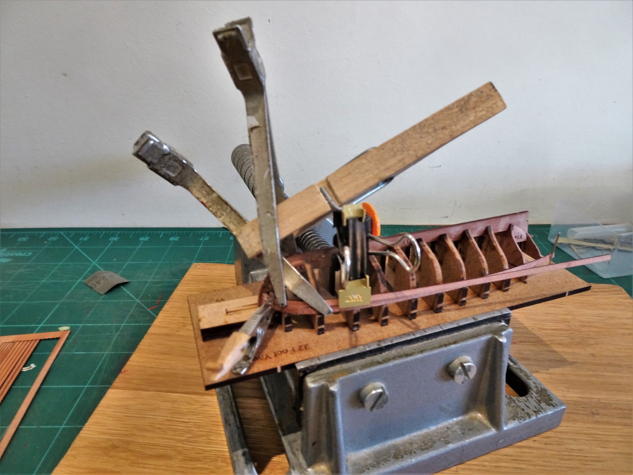
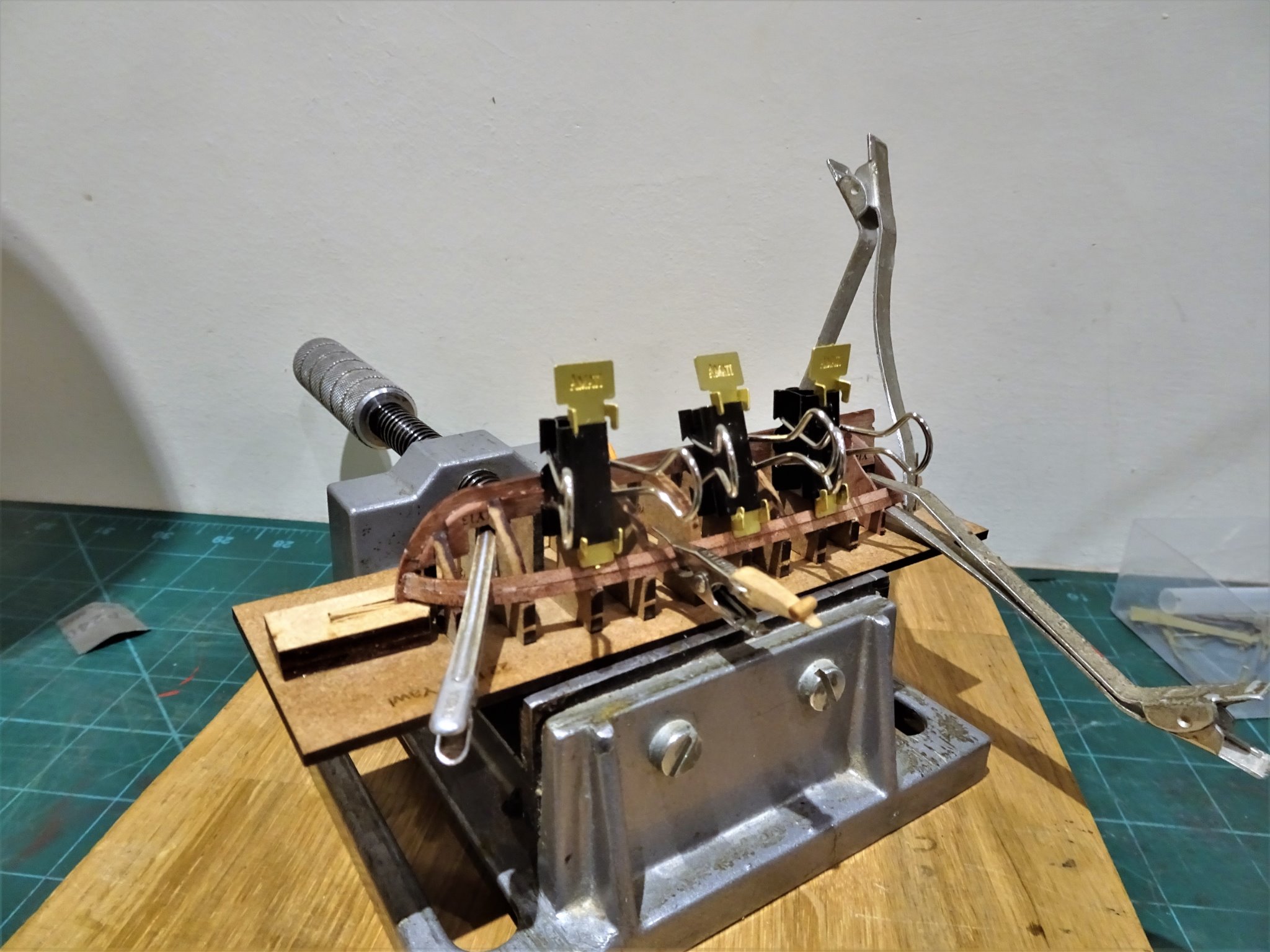
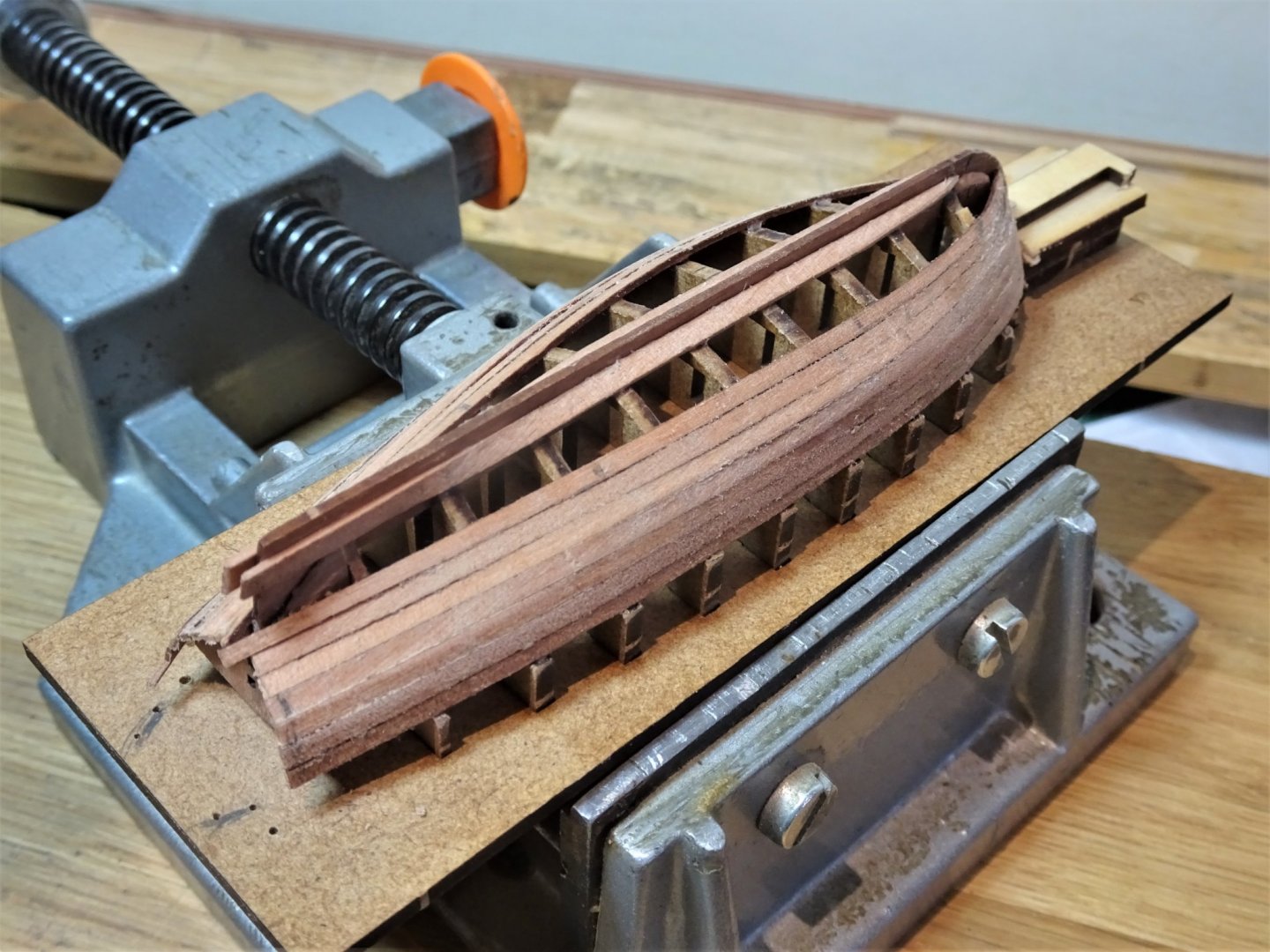
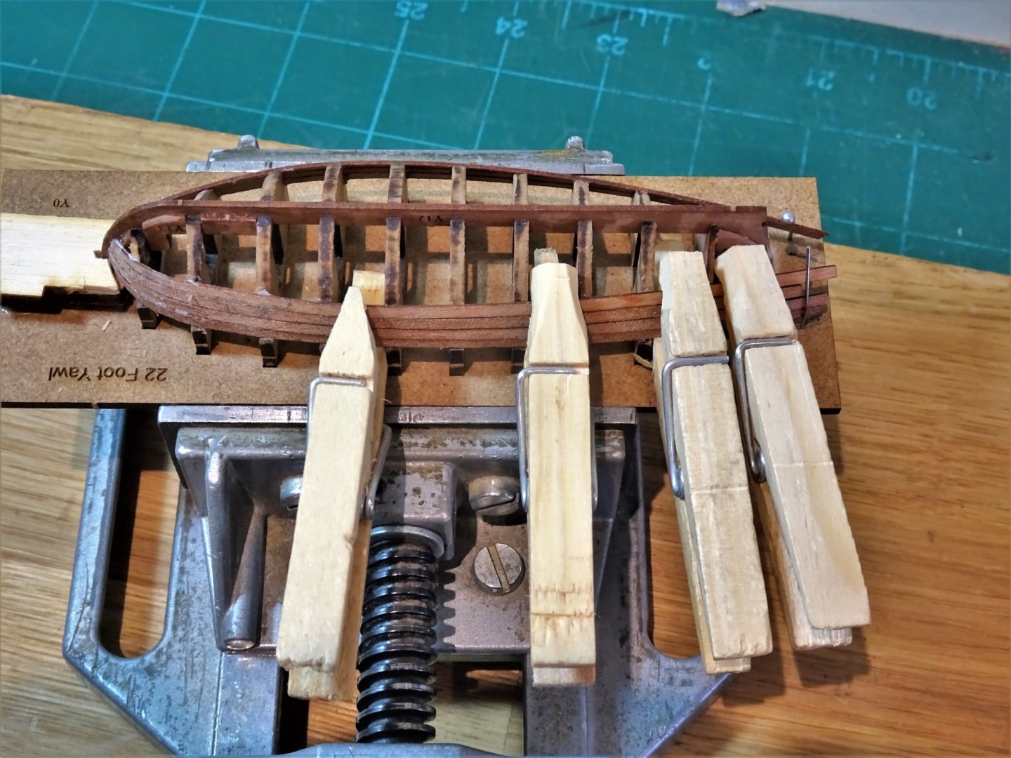
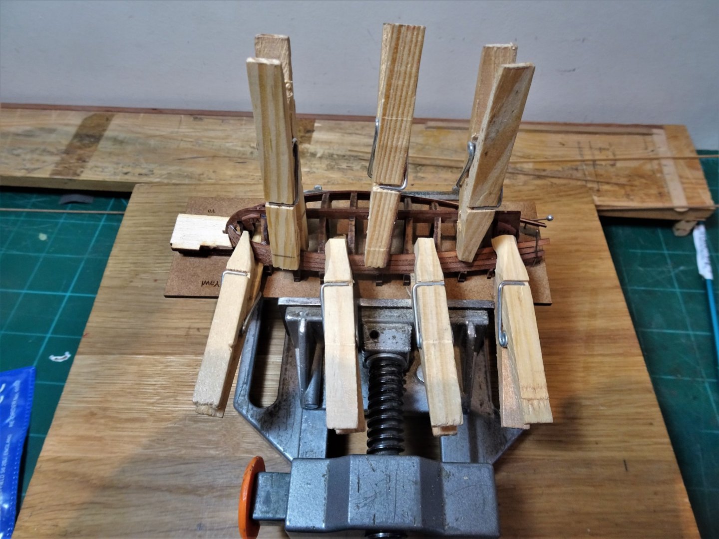
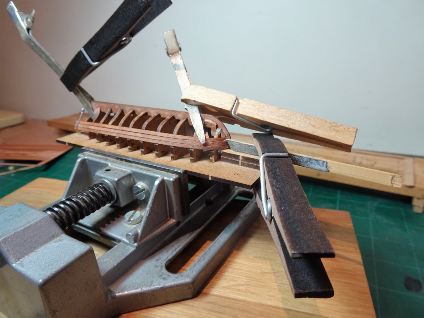
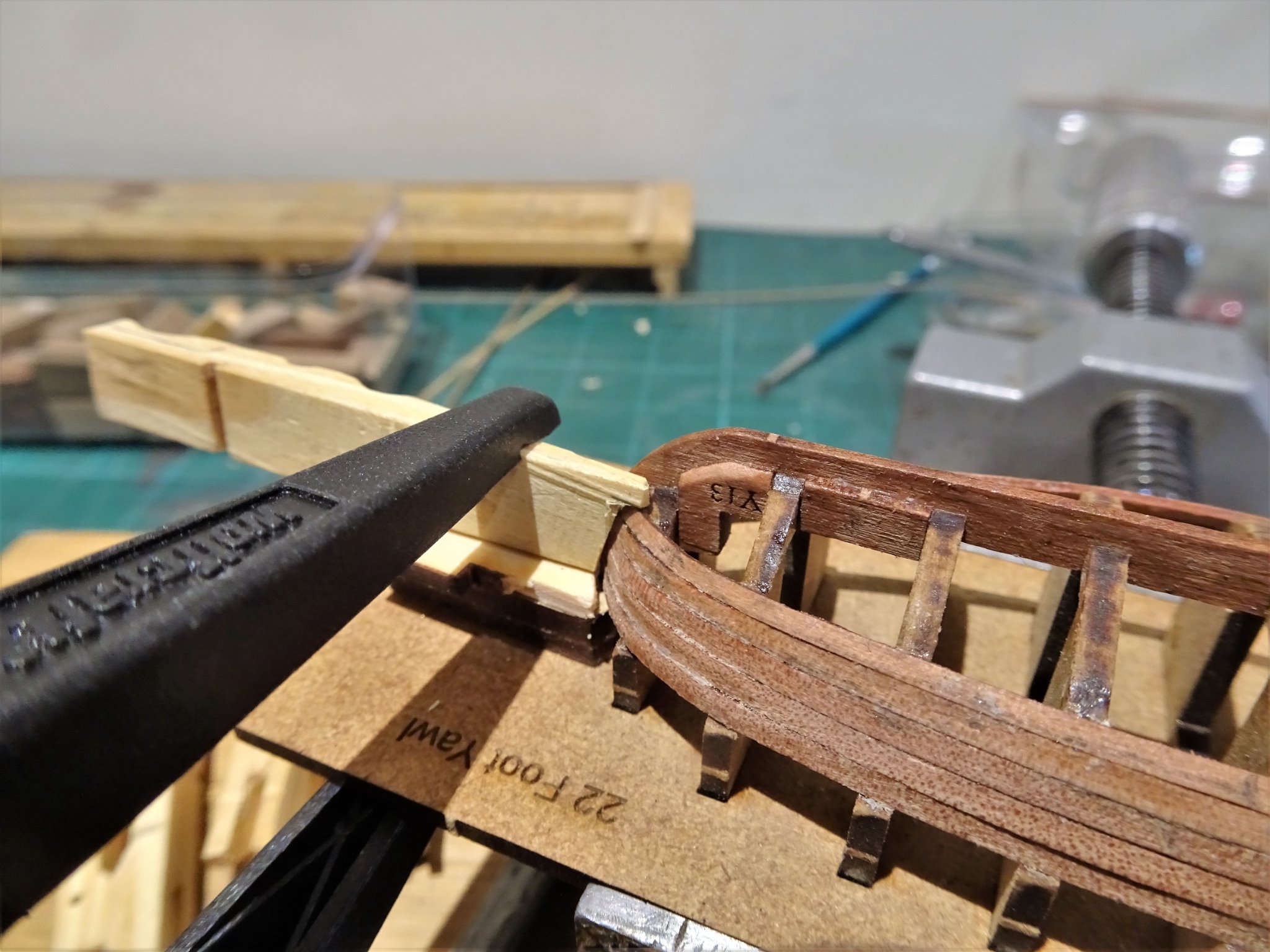
Post Seven ...and more planking Things start to get a little more interesting from the fourth strake. Bending both with the grain and laterally is indicated at the bow in addition to the taper. So the procedure is. Mark and taper. Mark and edge bend Round bend Bevel Hope it fits 🤔 My newly found hobby of how many clamps can you fit onto a 105mm hull continues. 00119 00120 Even so more options are needed. As the planking continues the clamping space gets smaller and I didn’t find the Amati clamps particularly useful in these circumstances, effectively they are too large and don’t get a good purchase against the plank and frame. 00133(2) Whittling down some cheap wooden clothes pegs to suit make convenient clamps to hold the strakes. 00132 One type has a frame width slot on the back leg to fit over the frame. 00124 The other type is shaped to fit between the frames to hold the strakes together. B.E. 28/01/2021


.thumb.JPG.4c72f4b8eedb80a3c1733d3d76a0c3be.JPG)
- 70 replies
-
- 7
-
-
- 22ft Yawl
- Vanguard Models
- (and 2 more)
-
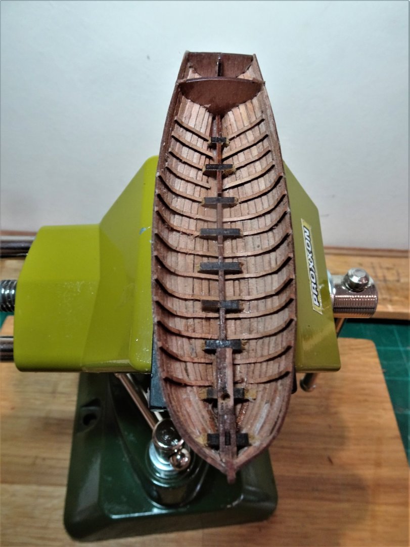
Post Six Planking continues. The second strake which also slots into the bow rabbet is now fitted. This strake is also untapered. 0073 Even with a rabbet this plank proves difficult to clamp close to the first two bulkheads, and a degree of inventiveness is required. 0075 The stern area is also tricky to hold the plank firmly against both stern board and adjacent plank. 00109 Looks like some bevelling is required between planks. 0107 The question now is how to proceed? I have decided to use ca to glue the bow area strakes. This is a tricky area to clamp and without the benefit of a rabbet may prove a frustrating exercise. The main issue with ca is marking the wood surface particularly on the inside which is difficult to remove, and won’t be obvious until the frames are removed. The get out of jail card is that the forward area of the Yawl is covered by a Fore deck which will cover any minor internal marks. Between this area and the stern I will use pva which can more easily be cleaned as I work along. I wanted to get an idea of how the planking will work out. 22 planks are supplied in the kit, 20 will be required to plank the hull, leaving two spares, one of which has broken during the bending process. I think that probably two extra planks each side would cover the risk of running short of useable planks. The third plank requires heat bending and tapering from the third frame forward. 00111 Using ca across the first two frames takes a lot of frustration out of the process and wetting the plank end aids rapid grab. 00115 For those who don’t know, what you see in these photos are Hairdressers sectioning clips, very useful for clamping lightweight objects where a firm but not fierce grip is required. They can be bent and filed into different shapes to suit and get into places where even other small clamps won’t fit. Having spent most of the day fitting three planks I have a growing appreciation of the fortitude shown by Mr Hatch in completing numerous of these teasing little beasts. HeyHo B.E. 26/1/21


- 70 replies
-
- 9
-
-
- 22ft Yawl
- Vanguard Models
- (and 2 more)


.JPG.fee54ccc5fec626225a7f38424a234a4.JPG)

.JPG.b2b7c5878c0fb80992a142cf37ba74f8.JPG)


.JPG.1c39faa55d796cc0b09960c892f40d1e.JPG)
.JPG.1c59d9eb9a497135d90fbcf1d4c74284.JPG)
.JPG.943e675bea96119b5bc20a97d9482d5c.JPG)
.JPG.703a31bbe5e25ab4307709cda2bed61e.JPG)
.JPG.a1a2ee8eccfba0ea15f1fe8e77e5948a.JPG)
.JPG.41936aabc5619b8c011a638cfdb26a68.JPG)


.JPG.f444e6094277b288d482904d718e7d31.JPG)


.JPG.db07287f3b340d9fe0197e805d66cf75.JPG)
.JPG.804f3ee923771c6f6dc6952418c9b2b4.JPG)
.JPG.bb201f62e8965e13af200638b3dd3c29.JPG)

.JPG.462bd6f790e5255f0bc0c5613d4d509d.JPG)
.JPG.6f78c96bb0fddab1b94dbf042d25be64.JPG)
.JPG.814d3d4167acd7843698eda78b80ae16.JPG)


.JPG.fef940cad4d45428efd0e3c4e137bc36.JPG)