.JPG.ca33079f5815b861e67b9c2cccd37982.JPG)

Blue Ensign
-
Posts
4,572 -
Joined
-
Last visited
Content Type
Profiles
Forums
Gallery
Events
Everything posted by Blue Ensign
-
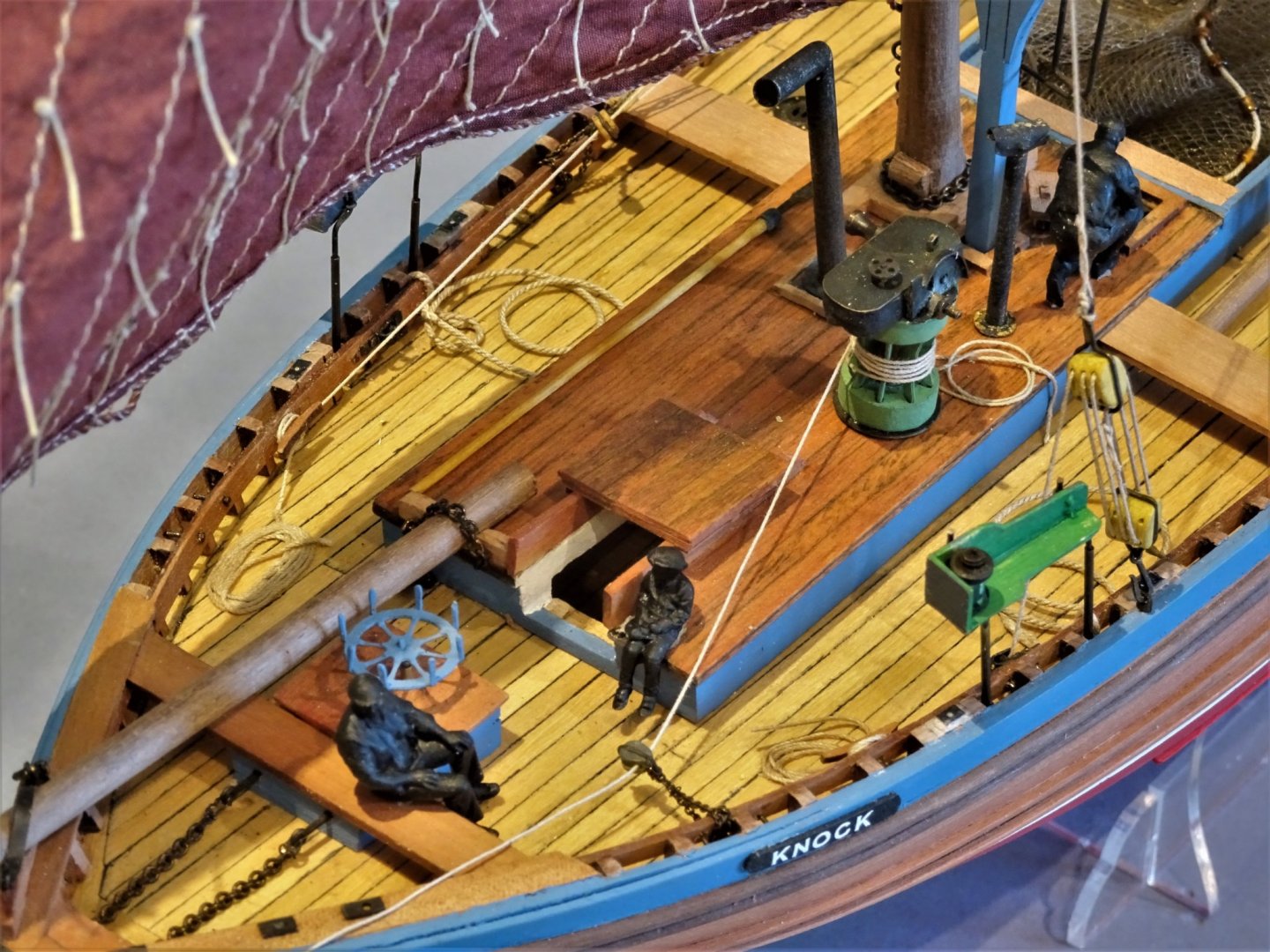
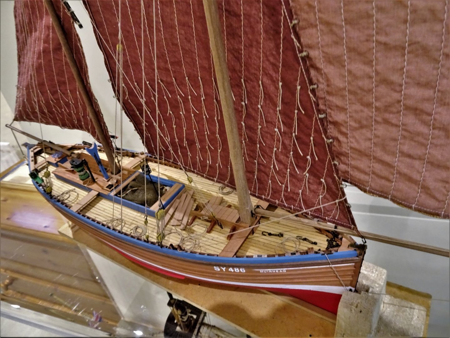
 Thanks Erik, a great find, I hadn’t seen it. Some great detail shots of equipment and how it was used, and of the scale. The warp rollers along the rail slotted into sockets are something I pondered about, altho’ I did fit the sockets. I note the relative sizes of the Cran baskets and net floats to the crew. 👍 B.E.
- 222 replies
-
- 1
-

-
- First Build
- Lady Isabella
- (and 2 more)
-
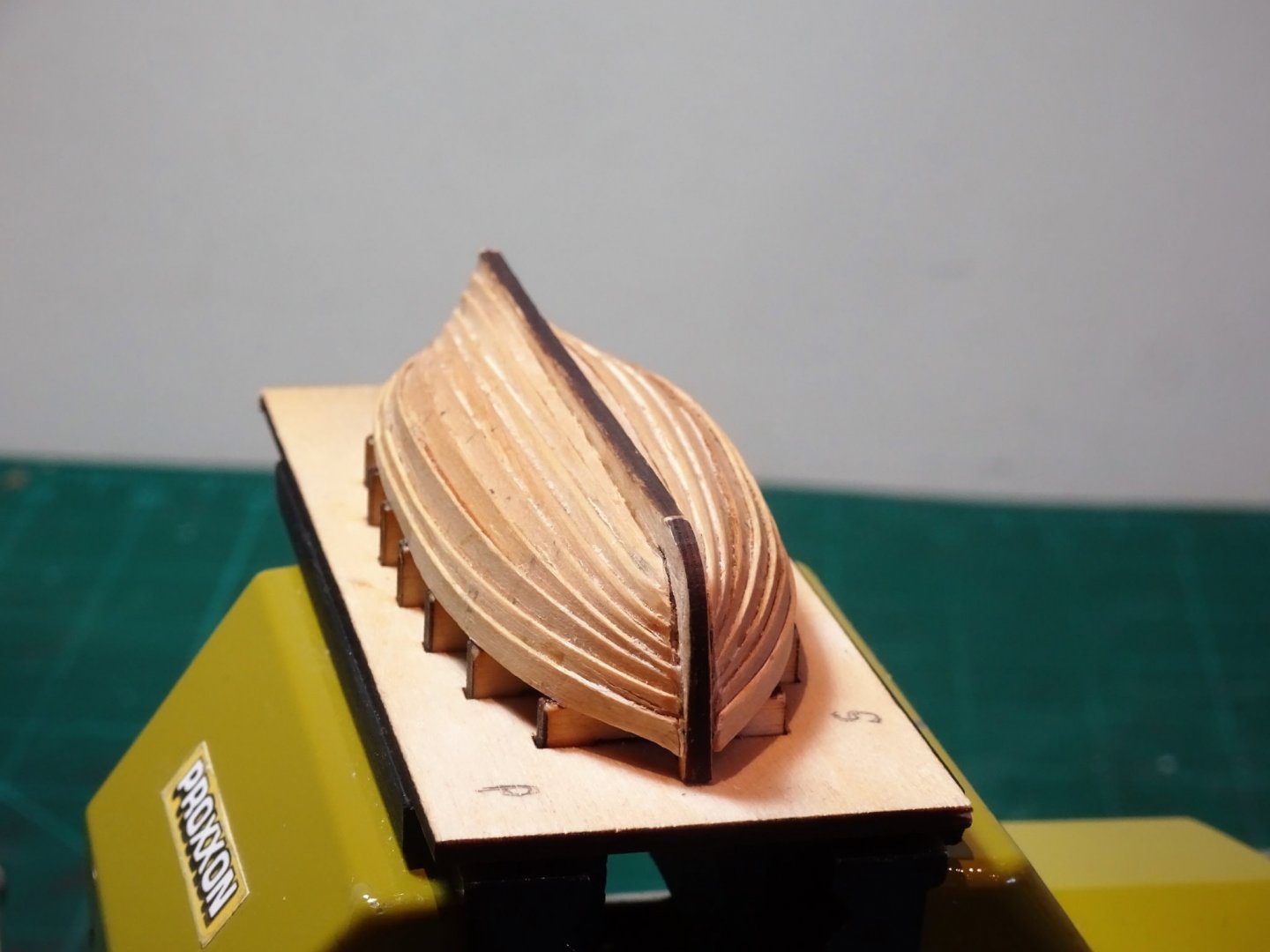
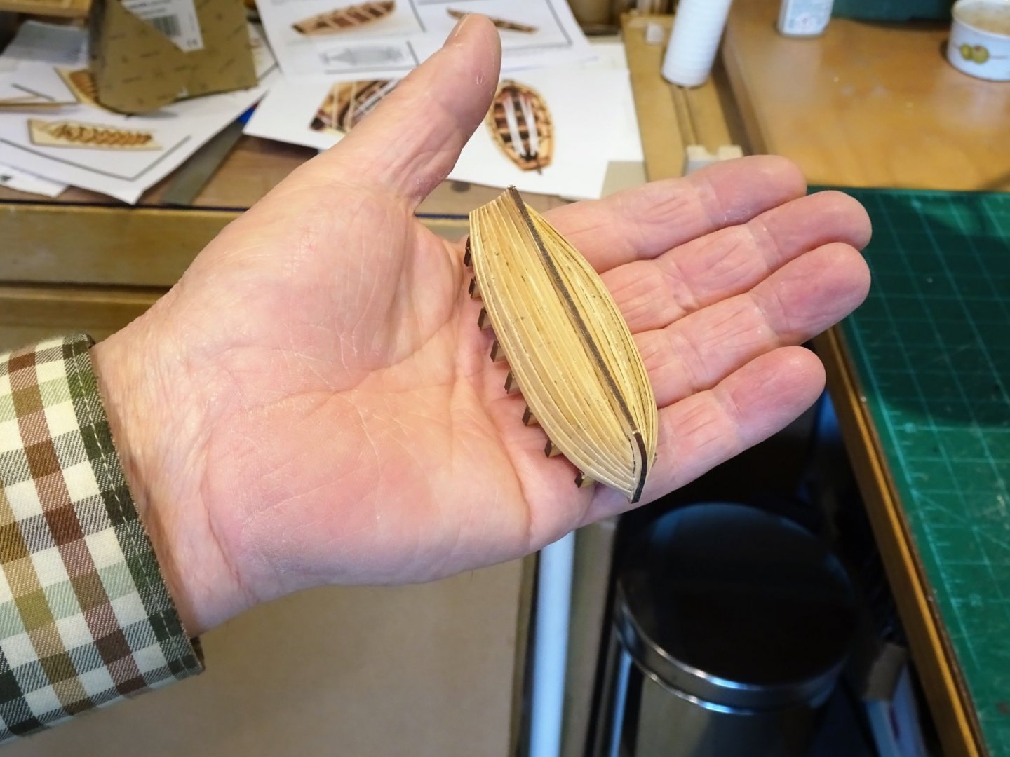
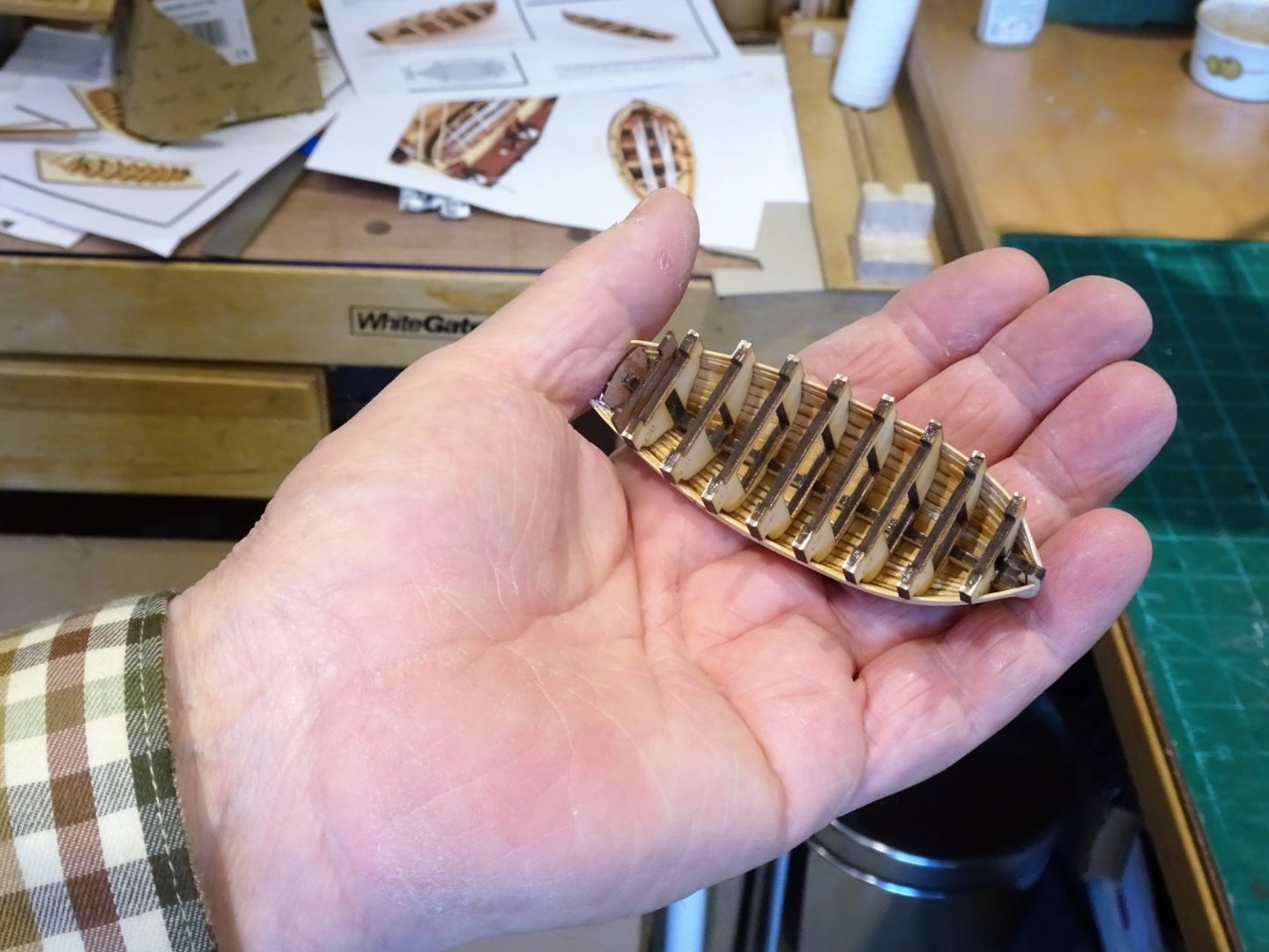
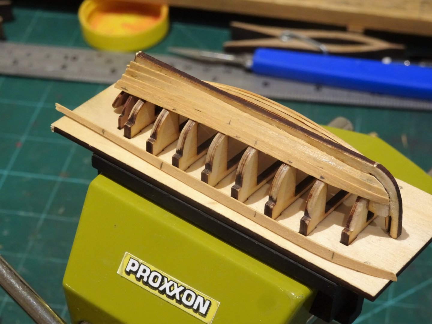
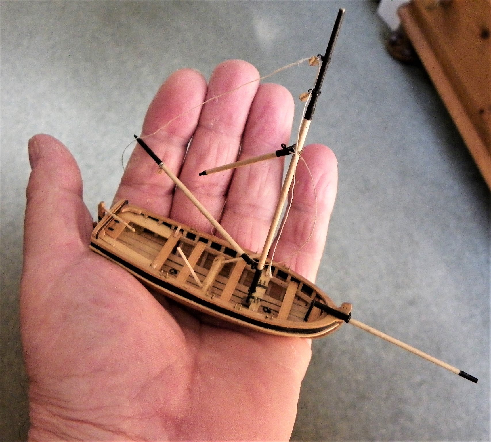
Post Four The planking is completed, it’s Lapstrake Jim, but not as we know it. Pictured here in its rough finish once fettled I hope it will at least look the part from normal viewing distance. 9732(2) 9736 Before removal from the building board. 9746 The boat is released by inverting the base board in a vice and gently tapping the lugs. 9750 9751 Before I remove the frames, I will attend to getting the outer hull as ship shape as I can. B.E. 09/01/21
.thumb.JPG.1aa6d1c7a5b17f1a2204ca41b9f54058.JPG)
- 70 replies
-
- 8
-
-
- 22ft Yawl
- Vanguard Models
- (and 2 more)
-
Thank you Guys for your supportive comments.👍 Postscript to the build Those familiar with my logs know that I use my build photo’s to produce a hard copy photo book recording the model build. I have now received my latest edition covering both Fifie and Zulu models. 9723(2) 9718(2) 9719(3) 9720(3) 9723(2) Once again I used Vistaprint to produce the book, and a superb job they have made. Regards, B.E. 08/01/21
.thumb.JPG.347e24f0ca8f903271a5467011af01c0.JPG)
.thumb.JPG.9706765d65aa968207b4ba3379e3e258.JPG)
.thumb.JPG.a305eaf7d3a679ce0c9596bffab51d76.JPG)
.thumb.JPG.c3f668585efc034d6193fc3beb52e4d3.JPG)
.thumb.JPG.230981ccc74071604c8a5a7beabb34a1.JPG)
- 261 replies
-
- 11
-
-
- muirneag
- vanguard models
- (and 2 more)
-
Thank you dunnock, I’m pleased you found it of use, and best wishes for your new project HMS Diana, she is a fine frigate. A build log log is the way to go to gain information and assistance with your build. Regards, B.E.
- 366 replies
-
- 1
-
-
- pegasus
- victory models
- (and 2 more)
-
Probably a wise decision, carvel is relatively straightforward, this is making it up as you go along.🙄 B.E.
-
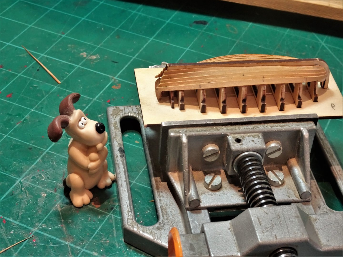
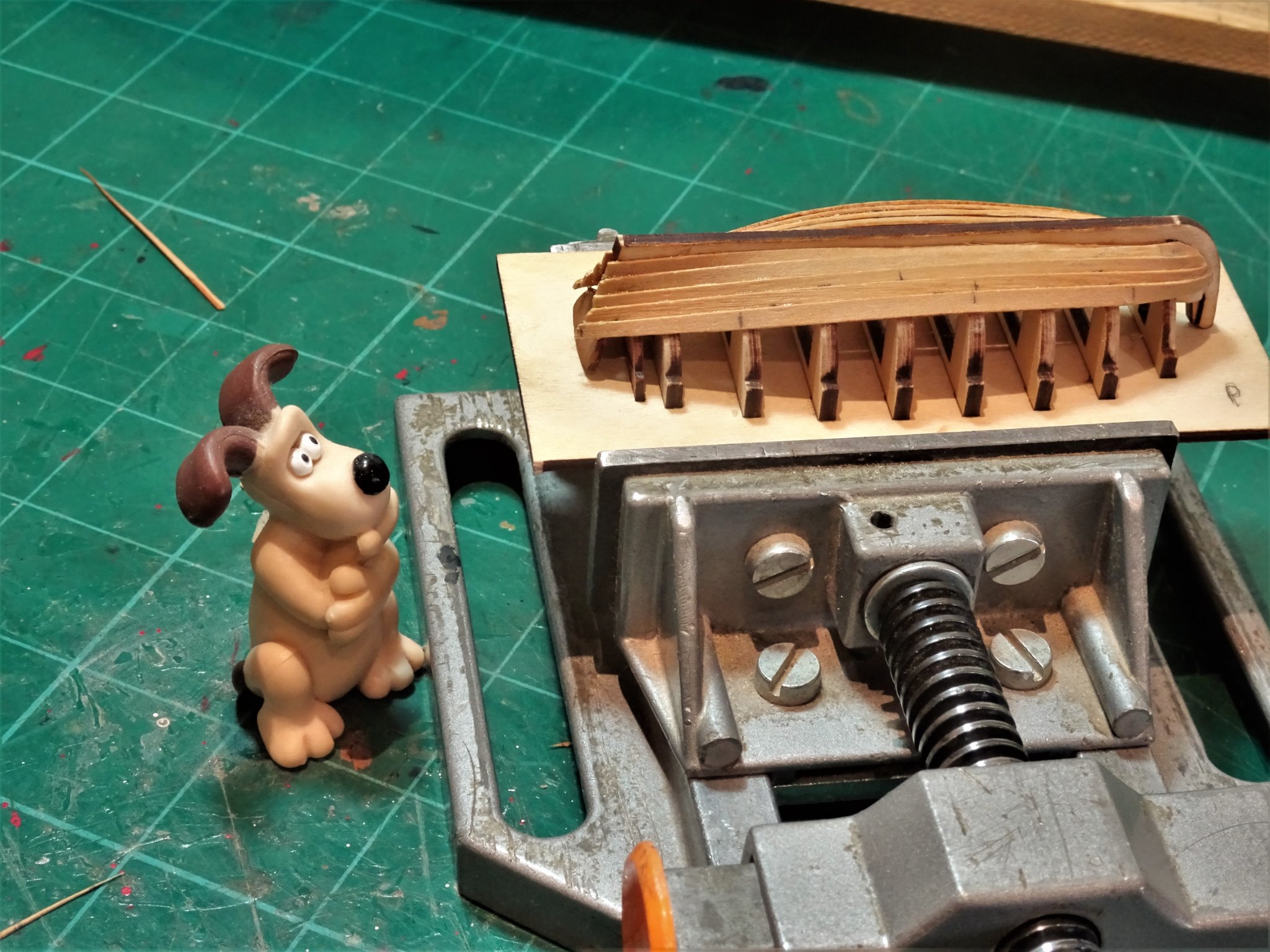
Post three. I have continued to apply the planks, tapering and heat forming to shape the strakes. I decided for me that any thoughts of using a tick stripping method to gauge the run was not going to work given the small size, even the thickness of a pencil point would quickly throw it out. 9705 A degree of edge bend was required to fit the first planks against the Garboard. 9707 I use the provided 2mm Pearwood strip to mark the overlap, and applied a simple taper to bow and stern. 9711(2) 9708(2) Still no idea how it’s all going to end up, what d’ye think Gromit. 9714 RUFF Give it a chance Gromit, it should get better. 🤞 🤞 🙄 B.E. 06/01/21
.thumb.JPG.3883b43c078b5020bdf0c082b3d8f7bf.JPG)
.thumb.JPG.bae9444b9c1ba097770db383971ecbfc.JPG)
.thumb.JPG.b7c5839b352b8ea2107cbd188e8d8d6e.JPG)
- 70 replies
-
- 11
-
-
- 22ft Yawl
- Vanguard Models
- (and 2 more)
-
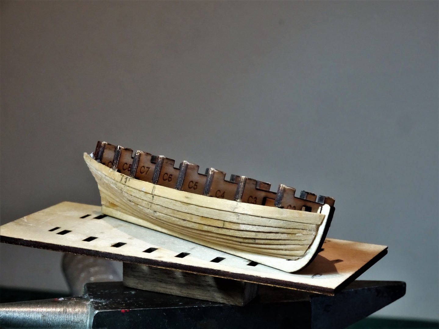
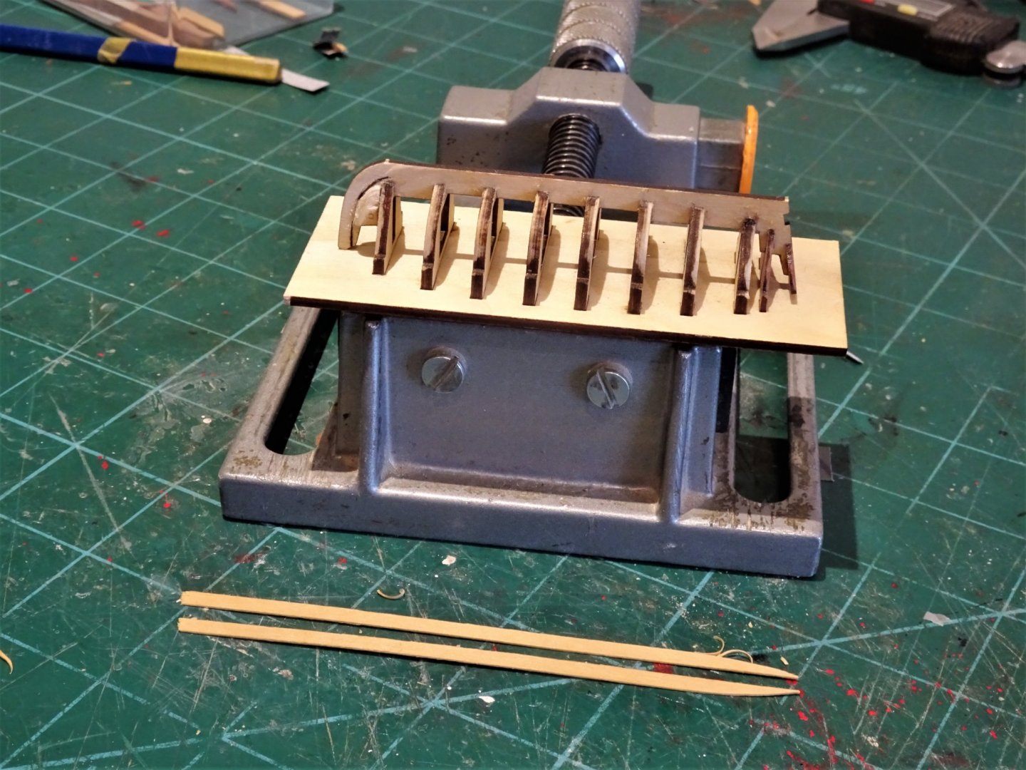
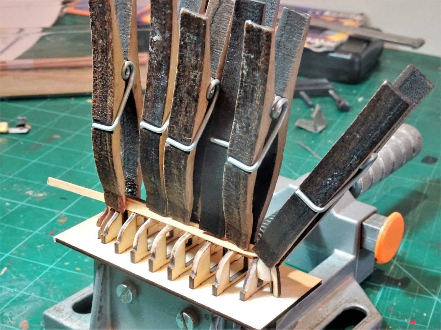
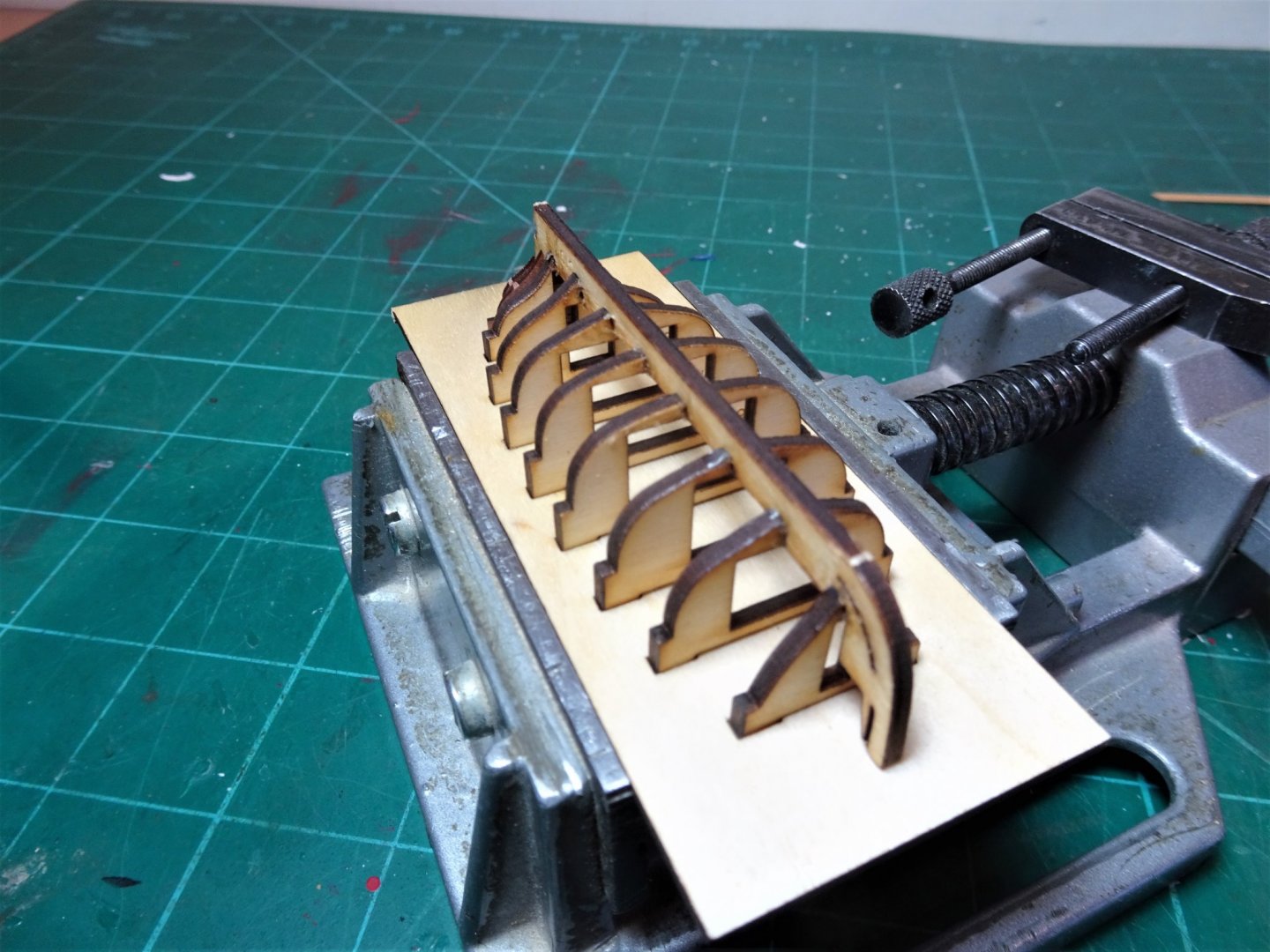
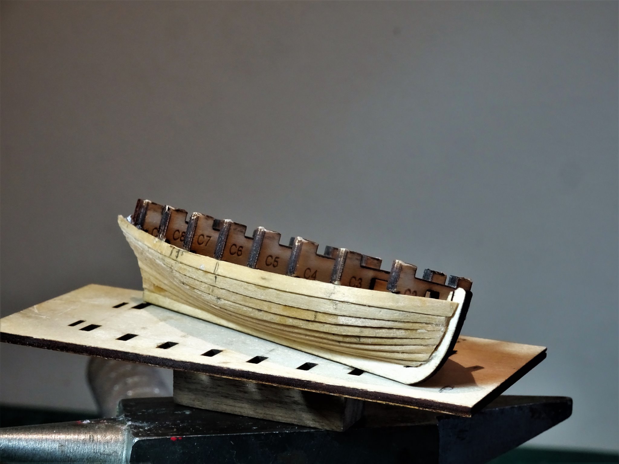
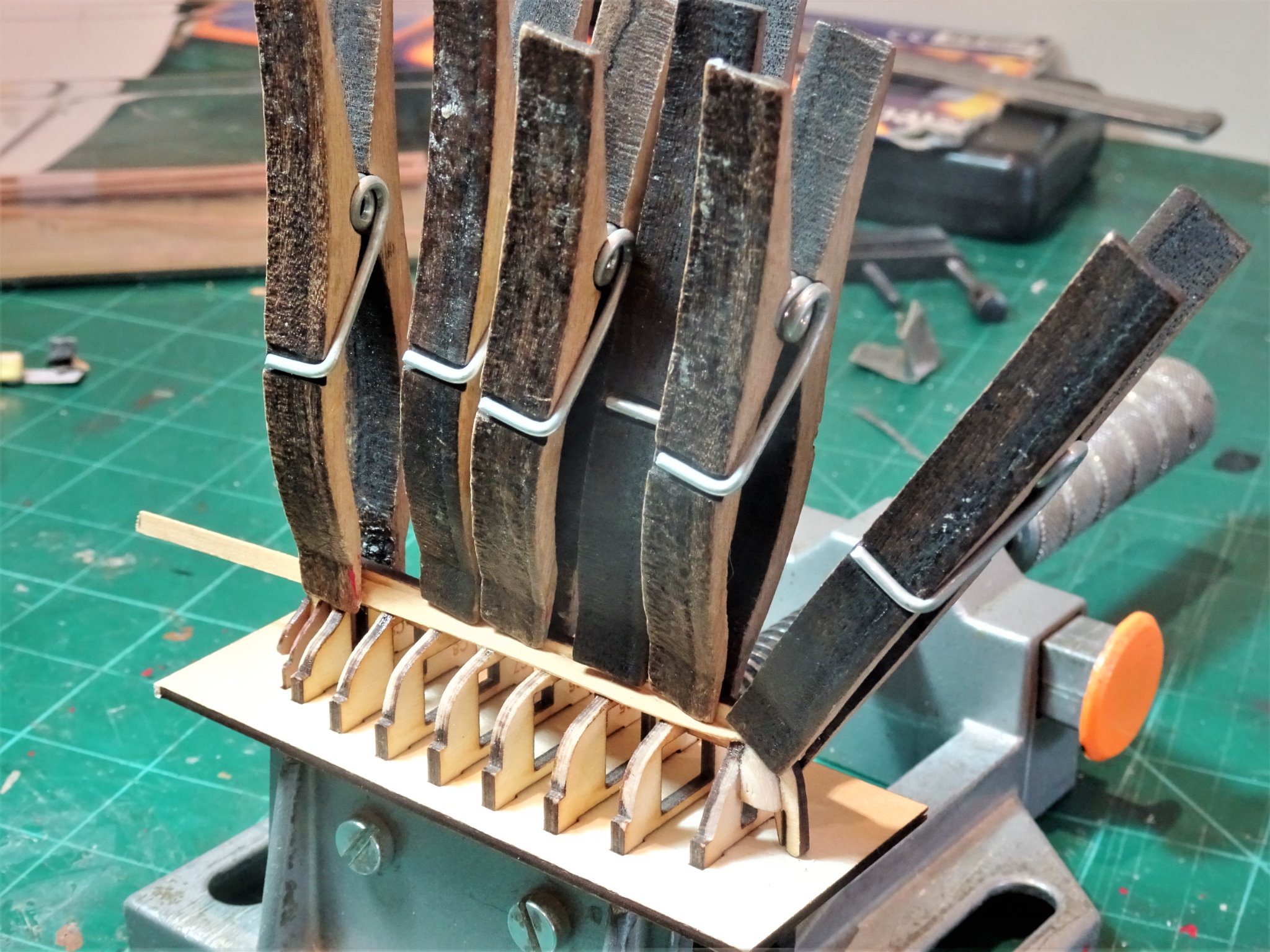
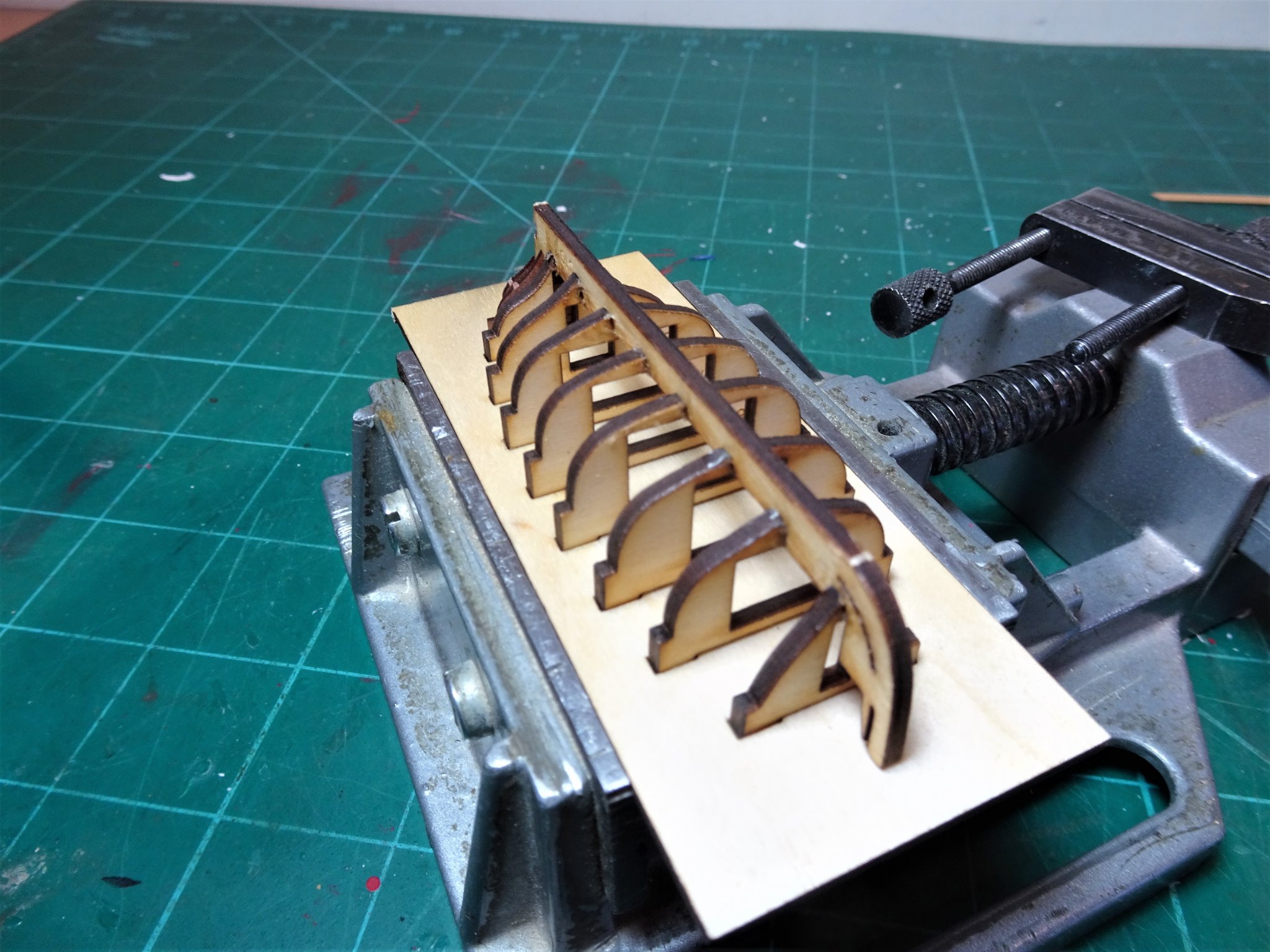
I had better hope it goes well then Tim 😉 Post 2 A little fairing is required to the bulkhead frames, which with this method of construction are held firmly on the building board. This is small scale stuff; the boat is a mere 80mm long but at least the base board provides a reasonable purchase to work on the frames. I have also added a grip to the bottom of the building board to secure in the vice. 9692(2) My first action is to make some suitable sanding sticks to carry out the task. I am using P240 paper pva’d to strips of varying widths. 9653(2) 9690(2) Once fitted the bow fillers need further chamfering to meet the plank rabbet in the bow. Planking The kit provides 2x1mm Pearwood Strip for the purpose of carvel planking. It is a simplified form with some tapering and allowing the strakes to sit where they run and infilled with stealers. I have decided to Clinker plank her with 0.7mm thick Boxwood strip. This means that the planking will start from the keel and run upwards to the gunwale. Despite my aversion to the stuff I will use thick ca to apply the planks given the small width and length of the strakes, and the need for a rapid grab. I start with the Garboard plank using 3.4 x 0.7mm strip. 9688 Garboards are tricky and I have shaped it purely by eye, bringing the forward point terminating on the first bulkhead. 9695 The boat is dwarfed by the clamps. 9697(2) Garboard planks in place. From this point on I will use card templates to determine the run and overlap of the planks. B.E. 04/01/21
.thumb.JPG.81ab997809e6978c9f839b4134cb3f55.JPG)
.thumb.JPG.848aec200b001a2d7fe82ca9cf3f0cc6.JPG)
.thumb.JPG.a624f8669afa5418642efa8702a95c61.JPG)
.thumb.JPG.e44d718eabee48f99ed2df24eed9073e.JPG)
- 70 replies
-
- 11
-
-
- 22ft Yawl
- Vanguard Models
- (and 2 more)
-
Good advice from Chuck, all you need to visualise is that the Garboard Plank will run along the bottom of the frames and into the rabbet. One piece of advice I would offer to avoid all that agony is to glue some securing strips along the top of frames to hold them rigid before you start the fairing process. These things are quite delicate and will snap off in a heartbeat without it. B.E.
-
I've just had a look back at my Pinnace build and the centre bulkhead didn't extend below the top rabbet line Are the others ok? B.E.
-
I think you may have got me there Tim, 😃 I don't think anyone else has charted building one of these, so it may assist others , providing I make a success of it. ps it would look good trailing behind Alert. 👍 B.E.
- 70 replies
-
- 3
-
-
- 22ft Yawl
- Vanguard Models
- (and 2 more)
-
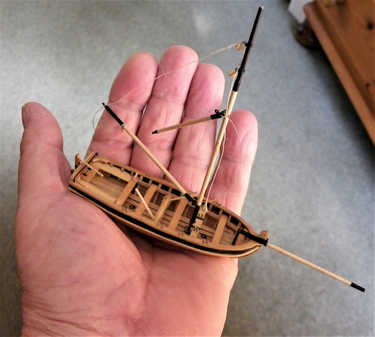
My basic issue is your assertion that modellers got things wrong because they had no experience of sailing vessels similar to the ones they were modelling, which is a somewhat sweeping statement. In the case of the Longboat there were valid reasons why they modelled it that way, other than ignorance. On the wider subject of rigging it is true that certainly some mass produced kits have glaring errors that those new to rigging may not spot, but there is no magic shortcut to the knowledge so fervently desired by those new to ship modelling. I have a huge collection of books on the subject, built up over many years, no one book covers all subjects or vessel types, but most derive from the works of David Steel who remains my go to source for 18th/early 19th century methods. His works are online and noobies could do worse than have a read of them. Realistically the best approach is to target your reference sources to the vessel type you are modelling, but this does incur extra costs. There is one free source of valuable information - right here on MSW. Read thro' the logs of experienced builders doing the vessel type you are interested in, and learn the abc of the technical terms. B.E.
-
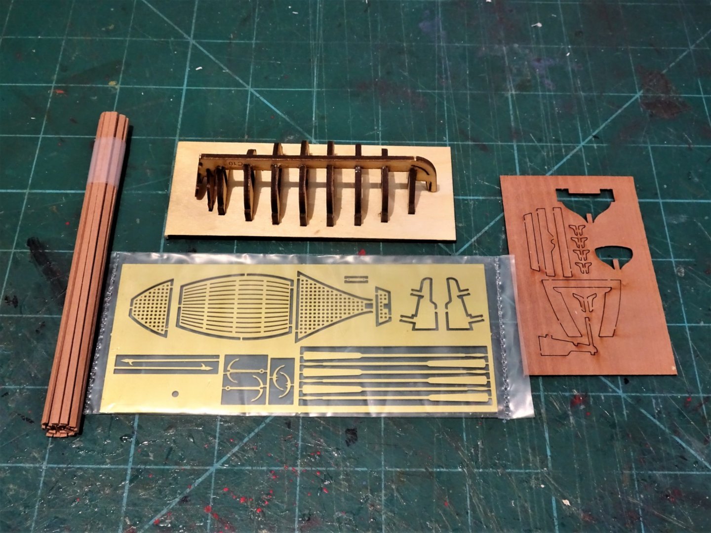
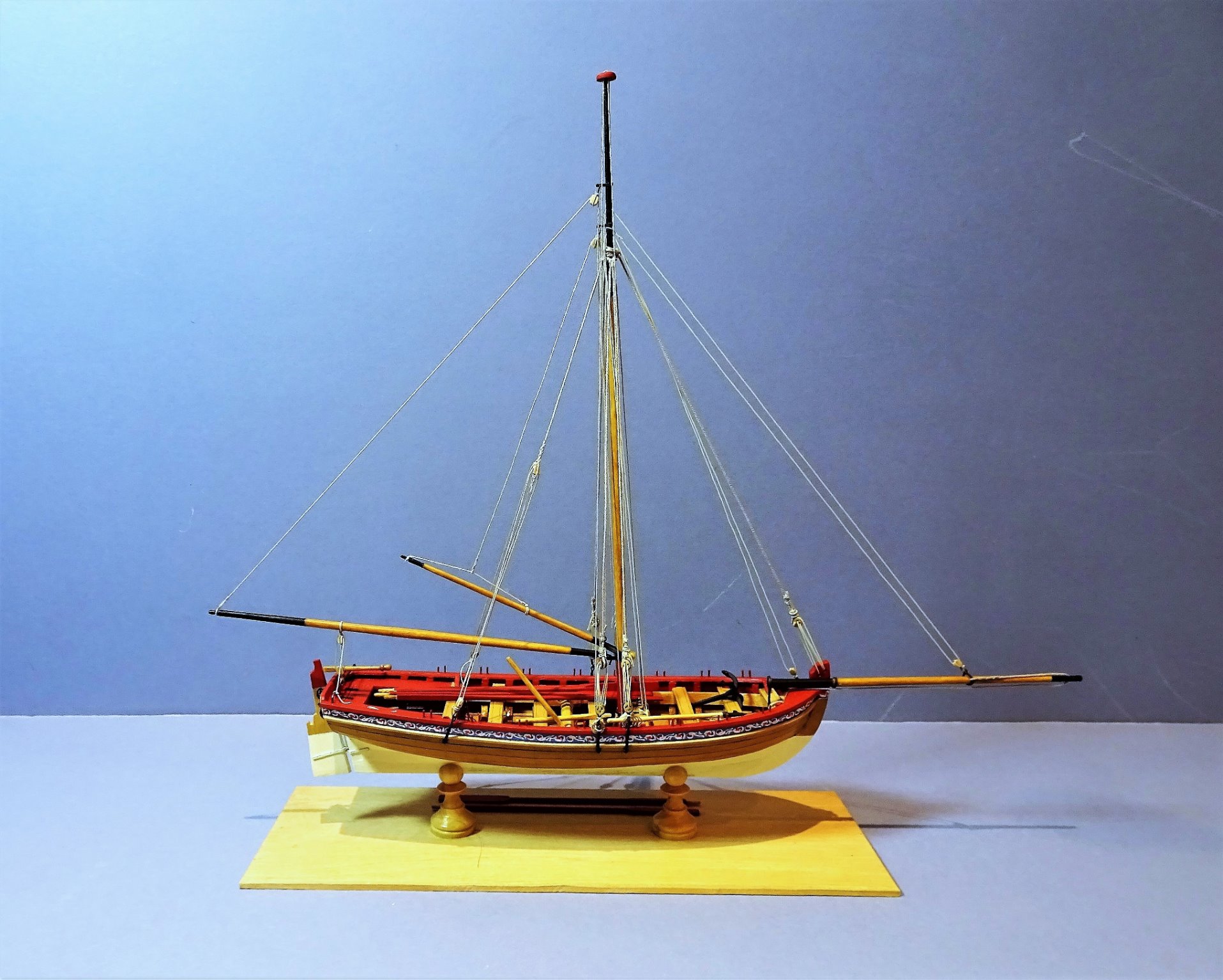
An 18ft cutter- a little filler between projects. One can always find a use for a ships boat and this 1:64 scale offering by Chris Watton of Vanguard models, fits the bill. As I’m in-between builds I thought this bijou kit would fill a few hours, and according to Mrs W stop me over fixating on the Bathroom conversion due to start next Monday. I am well served with ships boats in my shipyard. This 1:48 scale Model shipways offering of a Longboat. A fine little kit in my opinion, along with the Pinnace kit at 1:24. And this scratched 1:64 scale Boxwood version. 055 This was made for my Pegasus build using down sized plans from the Model shipways 1:48 scale Longboat kit. There are differences between Longboats and cutters, in terms of size and form, a major difference being that cutters were often Lapstraked rather than carvel built. I think Chris originally designed it as an accessory for his Speedy/Flirt kits, so I’ve included it in the 1751-1800 era section, but this style of boat would suit many eras. When I bought this kit I didn’t really have anything specific in mind but it could be used as a boat for Alert, or equally for a large fishing boat, depending how it is dressed. The mini kit comes with Pearwood planking, brass etched and Pearwood fittings. 9645 Not much to it is there, but that doesn’t mean it will be easy. 9639 The frames slot into a building board and over this the hull is planked. 9643(2) One of the bow planking patterns that require bevelling before fitting. These are tiny pieces to hold, I used a Tool maker’s clamp. 9650(2) If you don’t have one they are a worthwhile addition to your toolbox. So with the jig/frames set up I need to decide whether to go off piste and Lapstrake her in Boxwood, or use the nice little Pearwood strips provided, and follow the carvel route. B.E. 02/01/2021
.jpg.327574f0f000b4f6054ea863d189a2b7.jpg)

.thumb.JPG.d2ec02c744945240a891eabb194fbb8a.JPG)
.thumb.JPG.3eb55cc0b8a29922708ec6dd4c1f5257.JPG)
- 70 replies
-
- 13
-
-
- 22ft Yawl
- Vanguard Models
- (and 2 more)
-
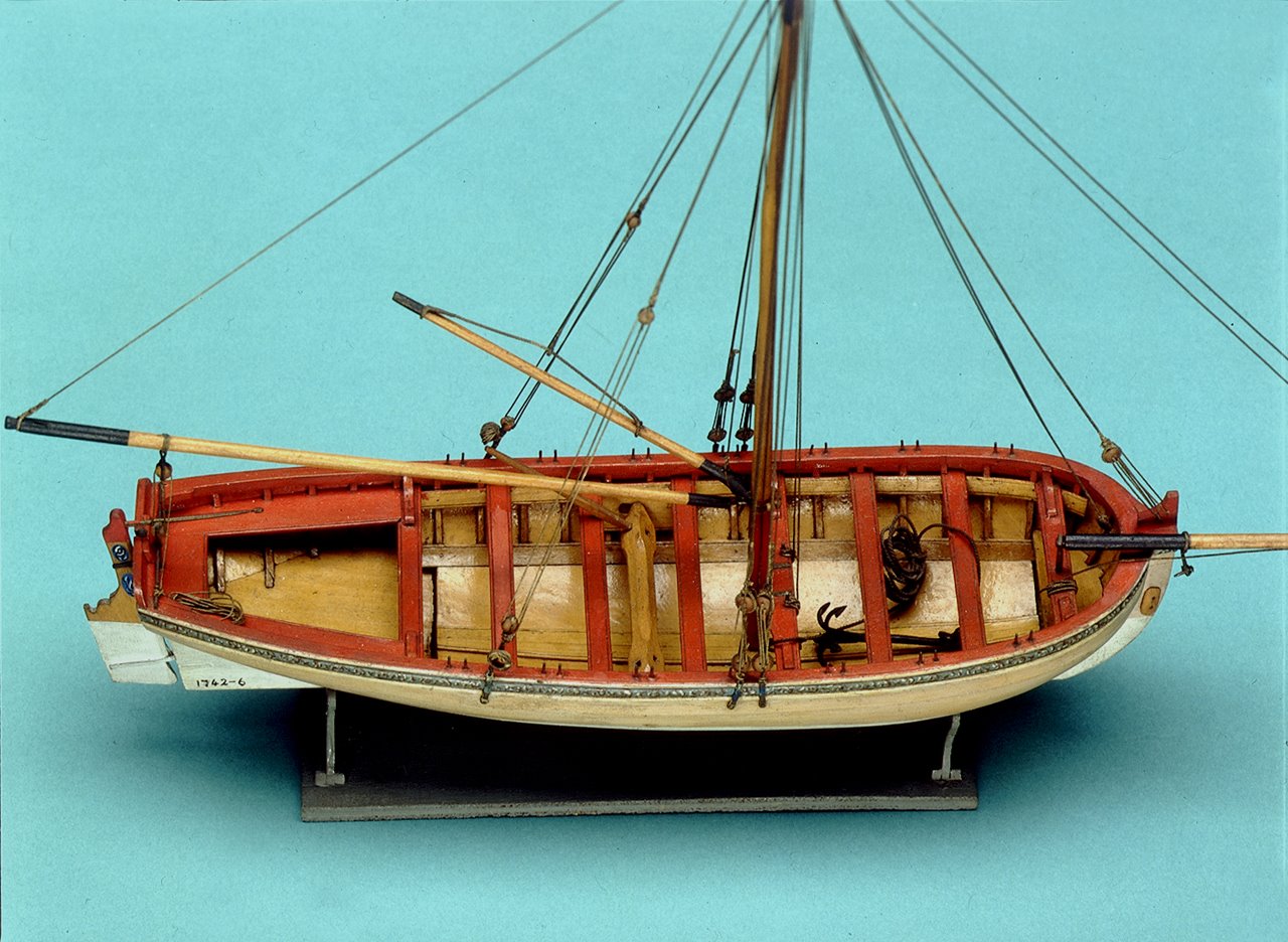
I've seen some highly skilled modelers who are distinguished by their careful research nevertheless make glaring errors in a model, particularly in things like rigging, because they obviously have no experience sailing vessels similar to the one they are modeling.*) The glaring error referred to by Bob, is something that has been discussed a lot on MSW., primarily if I recall correctly on Chuck’s Medway Longboat build. To the modern eye certainly having the iron horse below the tiller looks distinctly odd, but we can’t get away from the fact that contemporary models and plans show it this way. Notably the Longboat on the Medway model in the NMM.(1742) There is also an 18thc draught of the masting and rigging of a 32’ Longboat showing the same arrangement. So, the modern model-maker has a decision to make, to ignore historical evidence on the basis that it must be wrong, or go with the best evidence we have. When I built the Model shipways Longboat, after much thought I also placed the horse below the tiller, but not in ignorance as suggested by Bob, but rather on the basis that people of the time had shown it that way. Of course naysayers will say it’s probably a modern restoration error, but in the case of the Longboat, there is also the contemporary draught. B.E.
-
That's not an oar Richard it is the bar for turning the windlass, the oars are around two thirds the length of the boat. 😉 As a hint to the quiz - look to the rudder area , but this is not as straightforward as it may seem.🤔 B.E.
-
Very nice work Bob, This is a very decorative model with painted topsides of Red, White, Blue, and Yellow ochre, together with black wales. I would paint the bottom to give balance, and as others have said it does emphasise the rich Pearwood colour of which a lot will still be in evidence. Regards, B.E.
-
It certainly confuses the issue, I did a double take when I first saw the post I thought blimey he's moved quick, he's reinstalled the hull and finished off the model.😀 It is bad manners tho' to invade another modellers log, I see James has tried to give a large hint, to which Dan seemed oblivious.🙄 B.E.
-
Nice work on the stove Tim, and your gun tackles look good. You mentioned earlier about the issue of dropping ladders down the hatch when fitting. Ladders are quite tricky to fit; I usually attach a line of cotton to the upper tread, so if they do fall they are more easily retrieved. Regards, B.E.
- 164 replies
-
- 1
-

-
- fly
- Victory Models
- (and 4 more)
-
Looking great Rusty and there is a subtle difference in a 'hand' planked deck that I also prefer. I must admit that I was sorely tempted by this kit, it struck me that it would make a wonderful hull only Admiralty style model, I still may yet succumb😉 B.E.
- 201 replies
-
- 6
-
-
- Duchess of Kingston
- Vanguard Models
- (and 1 more)
-
Wow, so many supportive comments Guys , very much appreciated. Thank you all so much. B. E.
- 261 replies
-
- 5
-
-
- muirneag
- vanguard models
- (and 2 more)
-
Post 52 Muirneag completed Building this model has been a four-month journey of interest and pleasure and in a way I am sad to see it end. Firstly the detail shots. The final set of photos which together with the detail shots I hope may be of benefit to those following on with this kit. Fifie and Zulu Zulu and Fifie My thanks to Chris Watton for providing the makings for my conversion, but even with an out of box build there is a fine model to be had, and it is a good choice for those starting out in our hobby. With three Vanguard models built in continuous succession I am now taking a short break before I take on another project. I have a bathroom remodelling starting early in the New Year. So, thank you to those who have supported my build, in the meantime I will be compiling my usual photo book of the Fifie and Zulu builds. Stay safe and wishing you all a better 2021 B.E. 28/12/2020
.thumb.JPG.49f0c7fddbae51bacf6f47d16f375cb3.JPG)
.thumb.JPG.27b2b0a5a5444f628c6782f3a5aef7cc.JPG)
.thumb.JPG.fa7bdbd00ed1636a38a5e87412abde4b.JPG)
.thumb.JPG.46278a1f7b60e02bc8b55c4ac94b5277.JPG)
.thumb.JPG.2d3be52ba86094f38f45b95665a9f6bb.JPG)

.thumb.JPG.14599eac838f70ebb6b468ef647f4b08.JPG)

.thumb.JPG.f4b1539a87773b94cd170cafe2595ce1.JPG)
.thumb.JPG.d5da4fb294d32000fcb2501472050a57.JPG)
.thumb.JPG.a257a5347b7ea84aac559c6cdcb63f4c.JPG)
.thumb.JPG.c15a8cdc7ac70799abc313b22285966e.JPG)
.thumb.JPG.e73d9969e36e91c61e432061362969b3.JPG)
.thumb.JPG.b989ea0b875fc7d0c1ed23524f6fe62b.JPG)
.thumb.JPG.13411e73b8ee8d3a49a094fd162543db.JPG)
.thumb.JPG.bf1d609c13277f49dfb39caa67c49f0a.JPG)
.thumb.JPG.f8ac26418306685d1fd63c7af9cbddee.JPG)
.thumb.JPG.7d5ba85b2c426479e760f1bec5c9c385.JPG)

- 261 replies
-
- 26
-
-
- muirneag
- vanguard models
- (and 2 more)
-
She looks great Doug, and I love the stand, thank you for the mention, glad my log was of use. Well done. 👍 B.E.
- 40 replies
-
- 2
-
-
- sherbourne
- caldercraft
- (and 1 more)
-
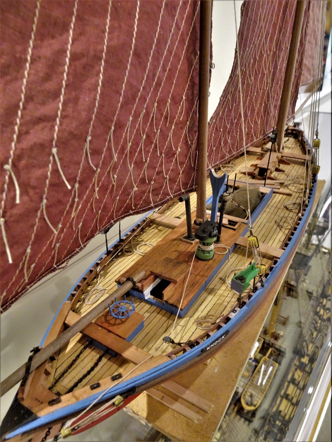
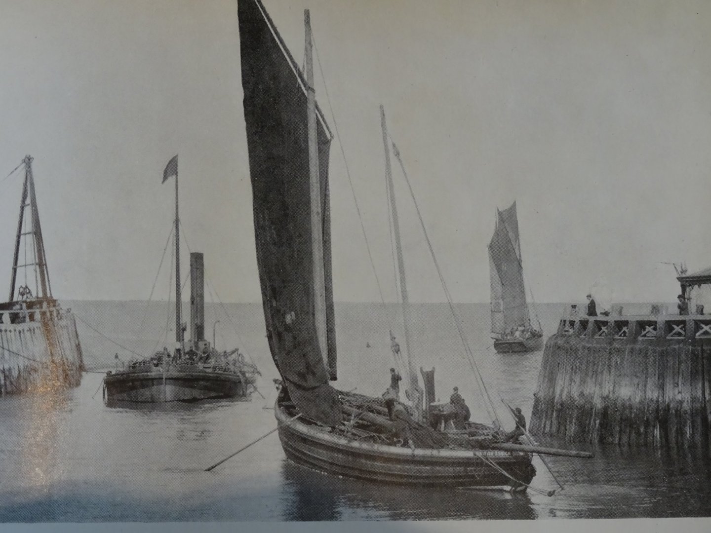
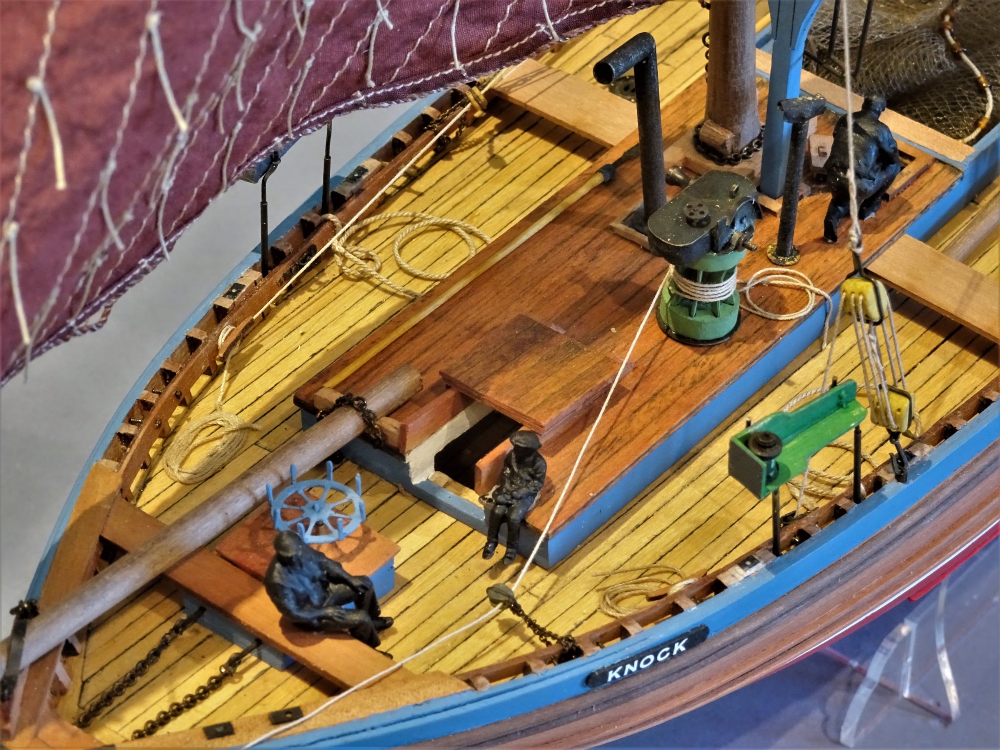
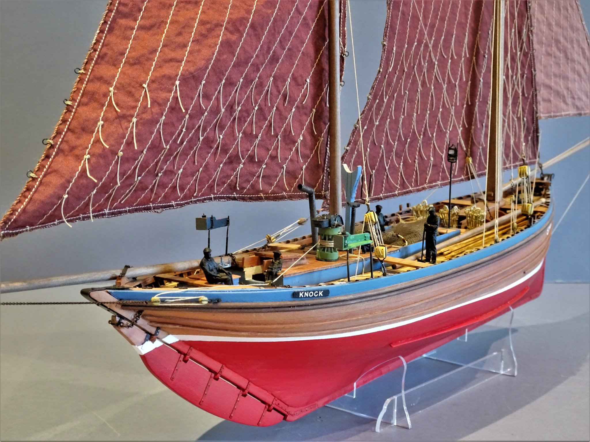
Cheers Guys, nearly there now. Post 51 Crewing the Boat I like to include a figure or two on a model purely for scale reference purposes. In the case of a Zulu the entire crew can be represented as it comprised no more than six including a boy. I prefer to display them as silhouette figures by either painting or chemically blackening depending on the medium. This also neatly avoids testing my very limited figure painting skills. 9494(2) For the crew I am using Modellu figures in S scale (1:64) and they are an excellent fit to the model and very finely detailed. 9501(2) Modellu don’t do specific Fishing boat crew figures, but their industrial, farming, and gardening figures provide reasonably suitable candidates. Deck accessories Edgar March gives useful details of these additions. Six oars 26’ long with a blade of 12’ x 5” They are more like sweeps than oars and were used to row the boat out of the harbour and very hard work it must have been. Sockets to take the thole pins were fitted between the stringer and rail. At scale these work out at: o/a length 124mm with a blade 57mm x 2mm. The oars at this scale are quite delicate. The shafts are made from 1.5mm Boxwood square stock and the blades from 2.4mm x 0.7mm Boxwood strip. 9520(2) When I made a prototype to these dimensions, I was struck by the seemingly long length of the blade which looked out of proportion to the overall length, but as best as I can gauge from photo’s, Gordon Williams reproduced them to the same proportions. 9543(2) There was quite an attrition rate in making the oars, ten started to produce six. Two Push sticks or wands 36’ x 2¾” ø These were used like punt poles for manoeuvring and fending off. 9541(2) At scale: 171mm x 1mm ø One Boathook 14’ x 2” ø 9544(2) At scale; 67mm x 0.80mm Spar for squaring jib when running 36’ x 6” ø 9525(2) I’m not quite sure how this was used, but it does present another large impediment on the deck. At scale: 171mm x 2.5mm This is a lot of stuff to be lying on the deck; how was it positioned to not interfere with handling the boat or when fishing; how was it secured to stop it sliding about or going overboard in rough weather? It was all certainly there as many old b/w photo’s, including the one below testify, The crew must have been pretty nimble of foot to handle the boat in a lively sea whilst negotiating all this deck hamper. 9527 Zulu British Ensign leaving port. One of the crew members can be seen using the Wand at the stern and one of the oars is also in use. The large amount of clutter on the deck is clearly evident. Still these items do add to the interest on the model and give some idea of the conditions in which these boats were worked. The next post will see the model finished with the completion photo’s. B.E. 27/12/20
.thumb.JPG.7e5ee0ae8a317be8951771a77525b0f5.JPG)
.thumb.JPG.7f35d491f658204453f05eafdc52a792.JPG)
.thumb.JPG.f8642ec48d2c201671722b8b76fd41ec.JPG)
.thumb.JPG.90ffb1e2901cc9a1d3b79fe3f697a73f.JPG)
.thumb.JPG.81edd27bfcac728efea0b54e4ef34980.JPG)
.thumb.JPG.34c87d6109745ffea44a05883b1473bb.JPG)
.thumb.JPG.a6a66e70c872ea35ee28d9ff1ba449fe.JPG)
- 261 replies
-
- 15
-
-
- muirneag
- vanguard models
- (and 2 more)
-
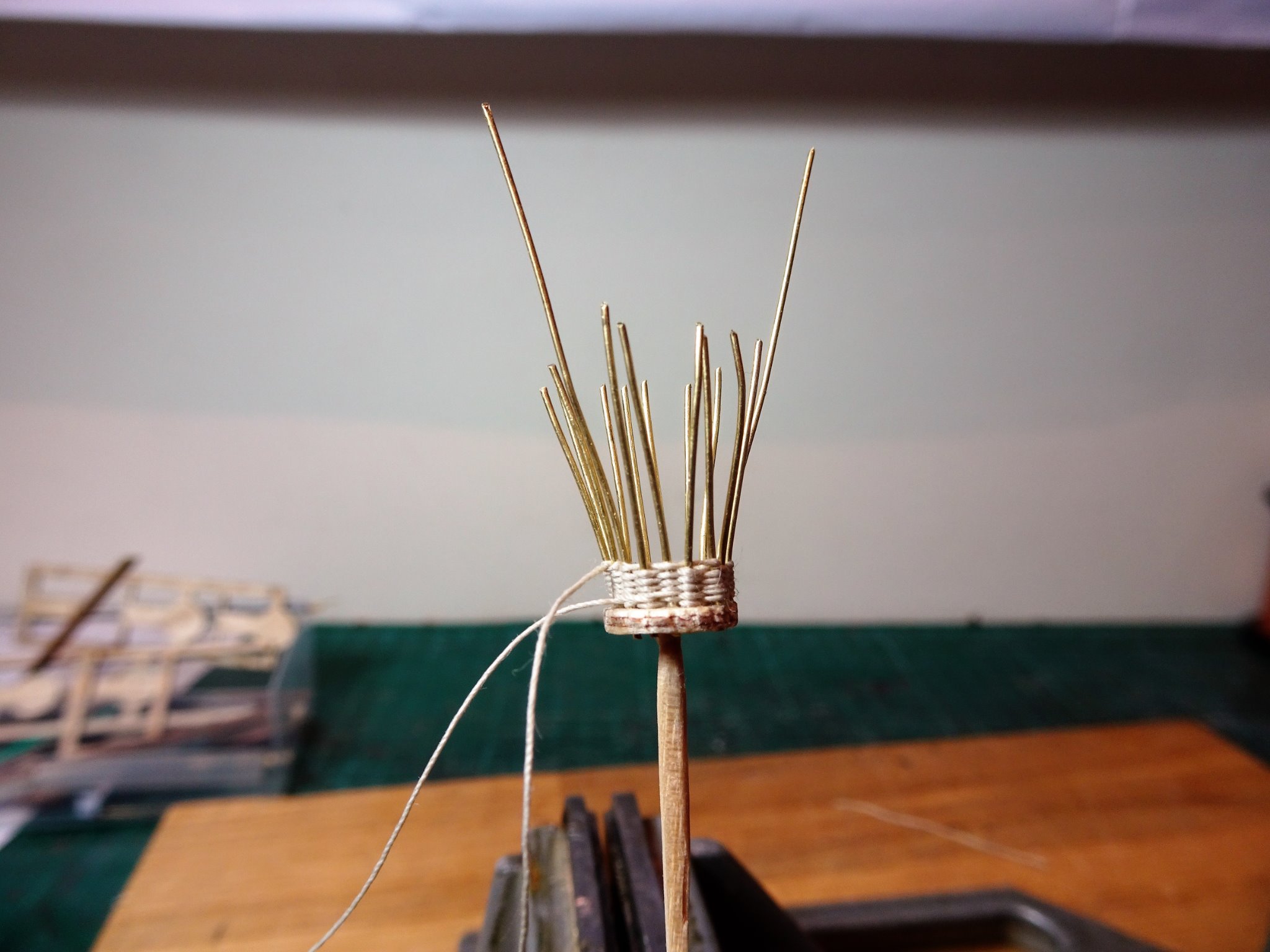
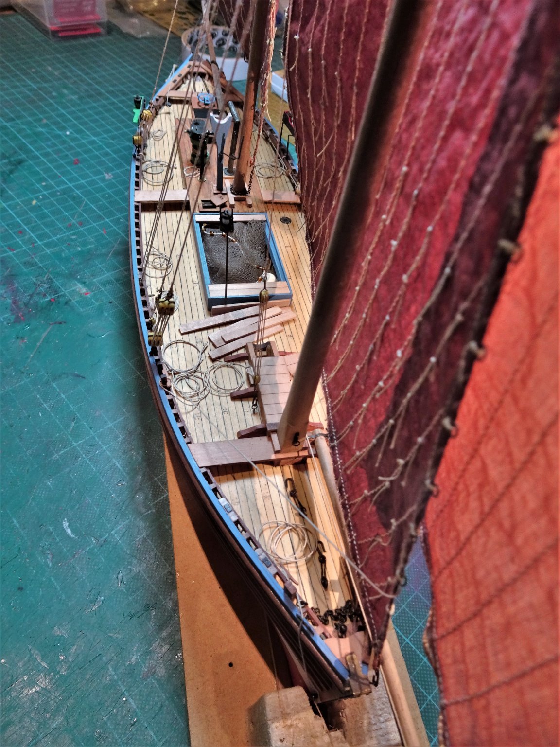
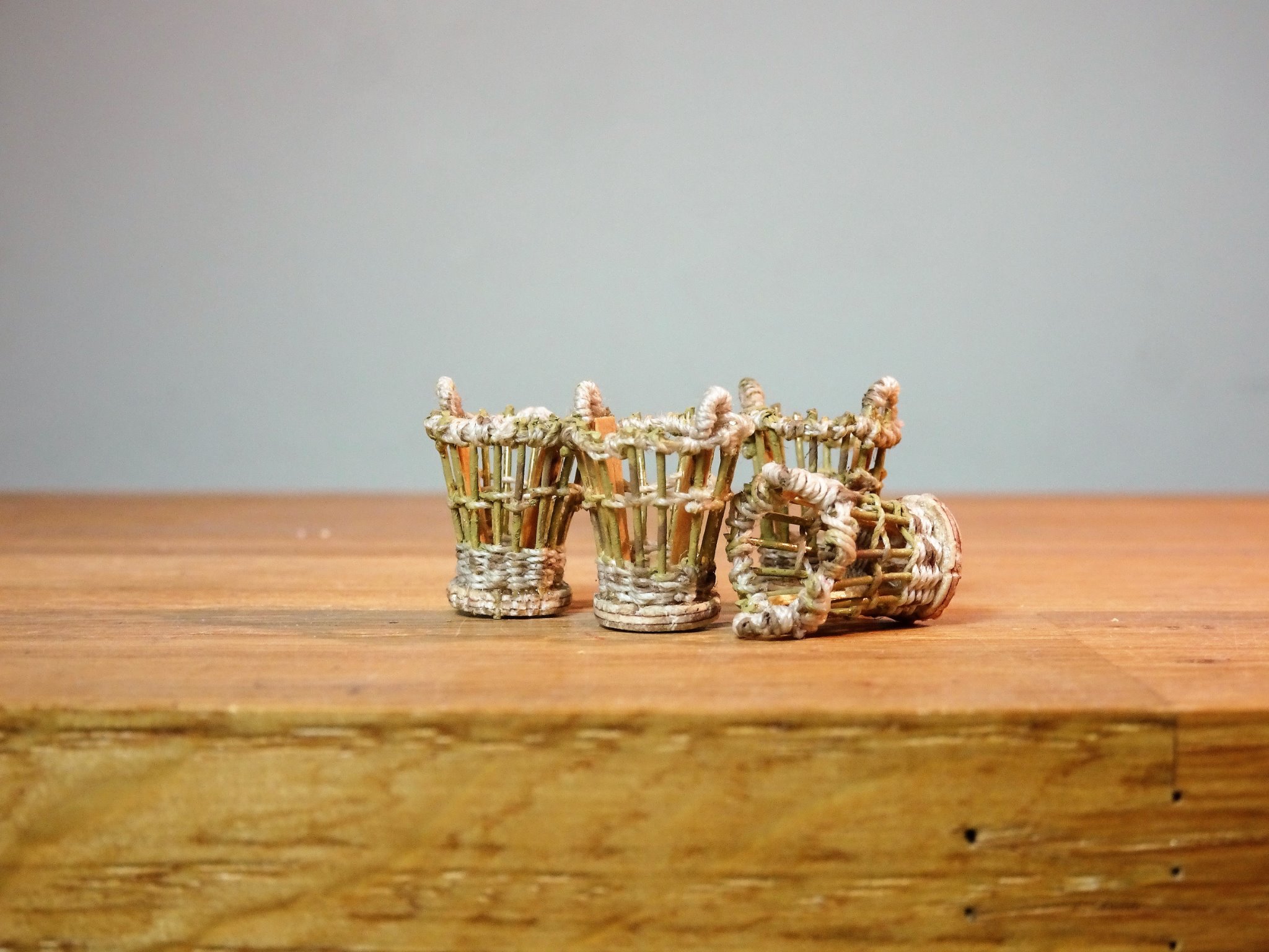
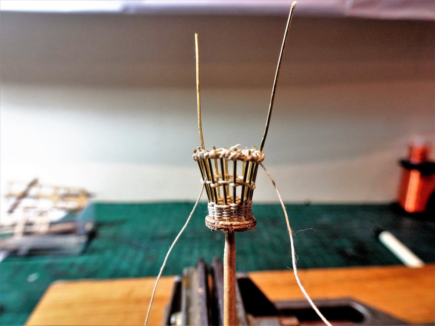
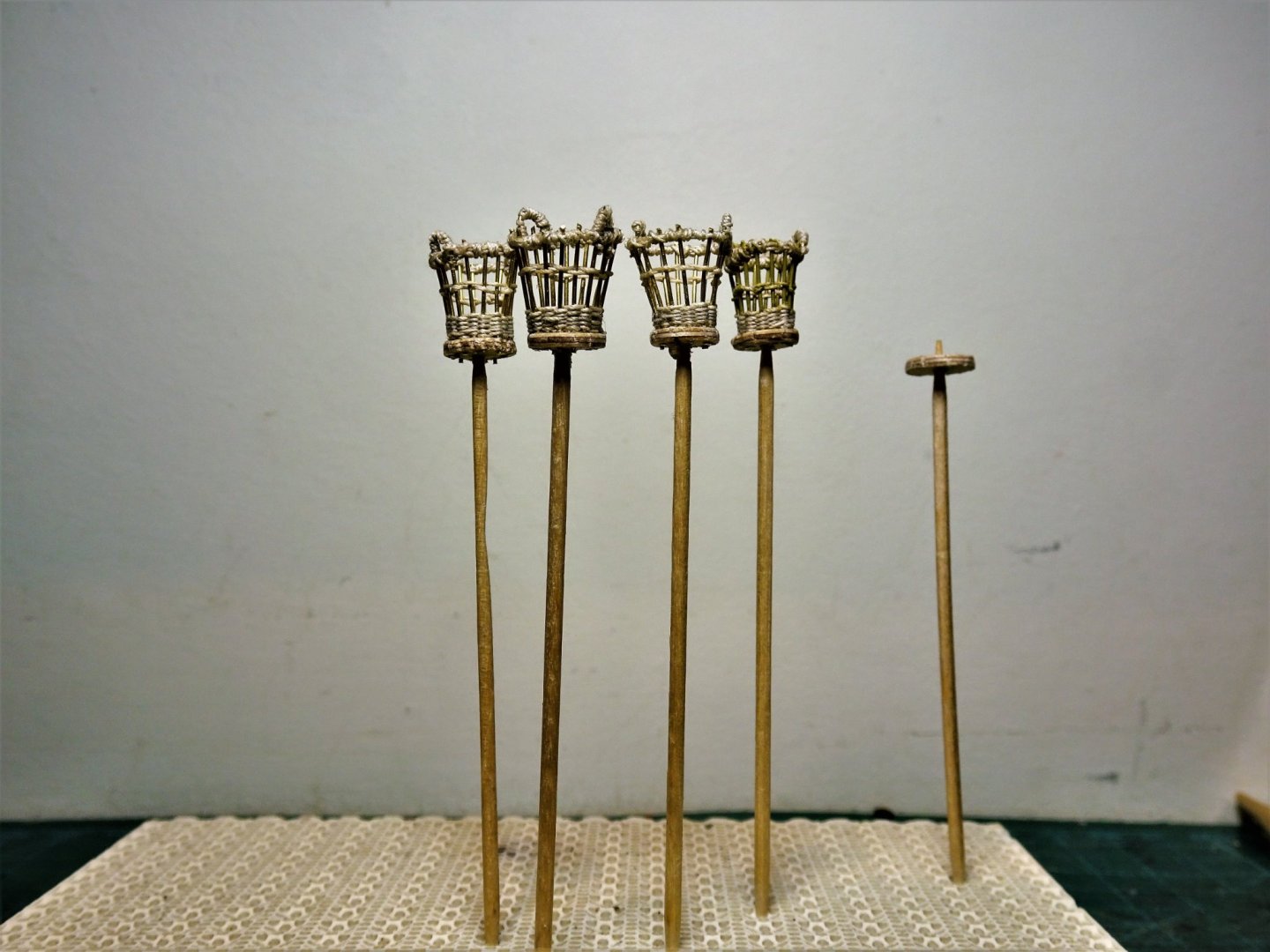
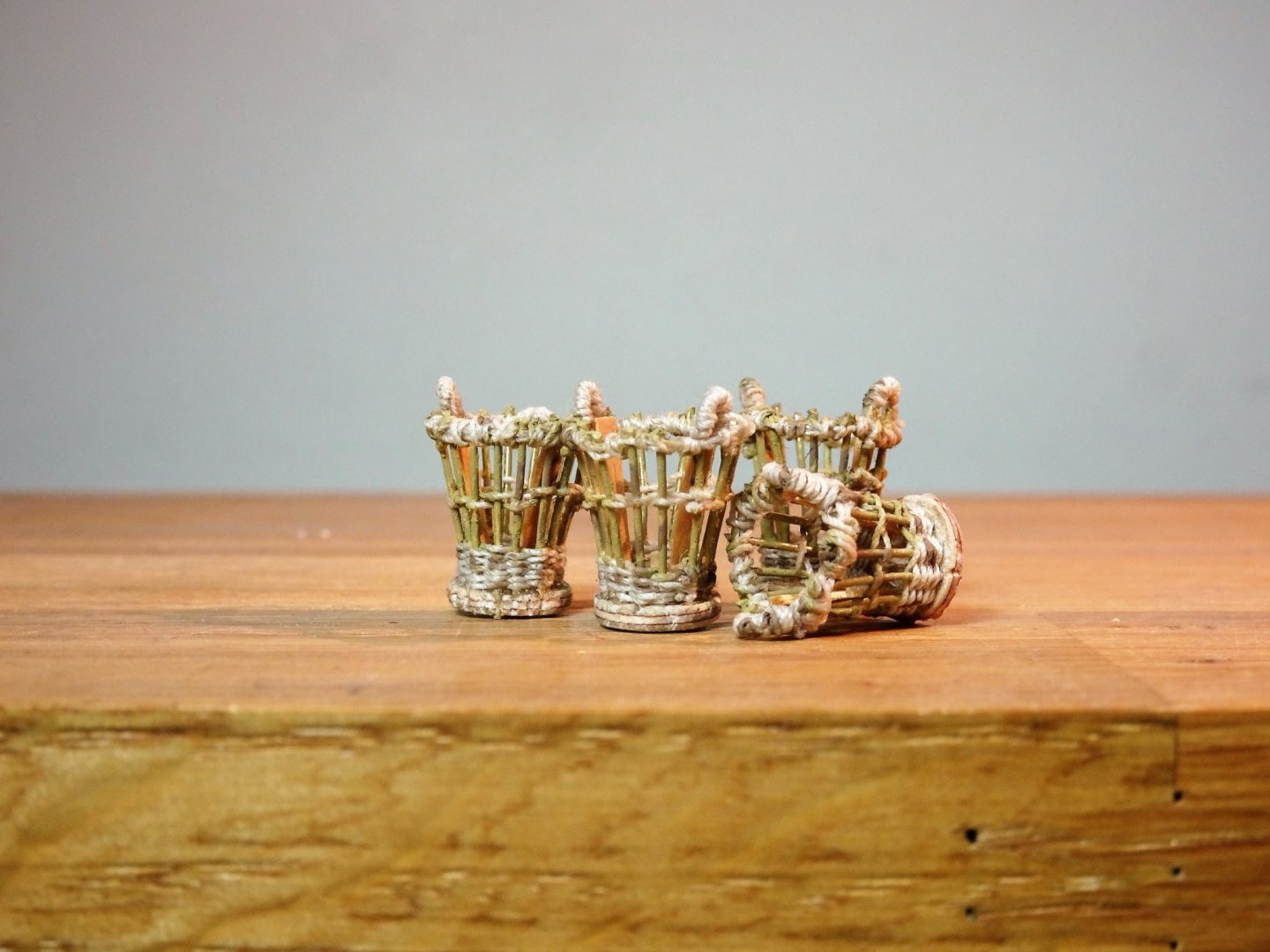
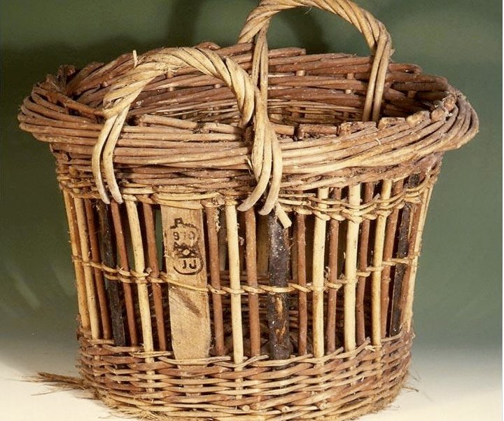
Thank you John and Martin. Post 50 Snaggings And Dressings As the build nears completion the eye finds lots of little areas needing attention such as marks on the paintwork, small items I forgot to complete, and general cleaning. Firstly, having got all the rigging lines in place the next task is to arrange the falls. 9508 I have deliberately not been too tidy in laying out the lines; having looked at many old photo’s of working boats of the era, Navy style is not to the forefront of Fishermen concerns, but most of those photo’s are taken in port during the unloading of the catch when a degree of working detritus may be expected. 9506 The skill in the handling of those enormous lugs by only three or four men is beyond question. 9511 I very much doubt that the line falls were left in such a state that increased the risk of fouling or tripping, there were hazards enough in working these boats in an unforgiving North Sea. Dressing the model. Time for some basket weaving – a matter of Crans. Crans are the official measure of a quantity of Herring Their size was regulated and standardized by government decree as a legal measure. The 1832 Act set the cran at 30 inches high, the diameter at its widest 21.9 inches and at the base 18.9 inches – at scale this represents: H = 12mm, diameter at top 9mm, diameter at base 7.5mm I made a set of three crans for my Fifie build and I hope to repeat the exercise here with a little improvement. 9471(2) Basket bases In practice the bases would have been woven in the traditional form. 9477 0.5mm brass wire form the rods, 0.1mm line the weave. 9480 The long uprights will form the handles. 9502 Four is about as much as my patience will stand. The piece on the right is a gauge for measuring the top circumference. 9513 The completed set. When it comes to the Silver Darlings this is how they translate to a 1:64 scale. In this image about three times the size of the actual. Am I going to carefully cut out a crans worth ? are you insane! This is my last post before Christmas, but I will continue working on the remaining fittings. Stay safe folks in these strange times. B.E. 23/12/2020
.thumb.JPG.4e3374f6d5a1cb48bcbe133e983569f5.JPG)


- 261 replies
-
- 22
-
-
- muirneag
- vanguard models
- (and 2 more)
-
Nice work Rusty, and quick progress too. 👍 B. E.
- 201 replies
-
- 1
-
-
- Duchess of Kingston
- Vanguard Models
- (and 1 more)
.JPG.0c3bbdfbae0205eedc23340c9c8bcc62.JPG)


.JPG.0d8139025114d29a04b1a5544a3c0f88.JPG)
.JPG.4120b9ca6c3577fcbabdb1d5b394c1a6.JPG)
.JPG.6231b34bdd624f9ddafa39a194e44d38.JPG)
.JPG.cf229a7ac7aa820a4f8967e1039ac030.JPG)
.JPG.eacdcbc38081248a7f9ed0f4259500d7.JPG)
.JPG.da8b4aaea958075415dd8c7cd5902e09.JPG)

.JPG.0217c762bc9904adfeb462b841a4e6fd.JPG)
.JPG.d68efb1e86fc4534c562e801d8e6646c.JPG)
.JPG.6795b92f88d170725d2e0d962bbb34e6.JPG)

.JPG.d4d3777b4456490f3401647469940944.JPG)
.JPG.fca55a525dca4242846dfc63bde30fa5.JPG)
.JPG.0a16d2e68d52c89231038783f53deae2.JPG)
.JPG.6cb1c3167b3f689ac968c071cfe6d5c6.JPG)

.JPG.a52cc79853ee781b465800781df6ca7b.JPG)
.JPG.8c2571ac4a57fe5b1570b5531ee23747.JPG)
.JPG.aadd6babd1fb5fbae08927245a2f4cd1.JPG)
.JPG.240d01f5ad6757fd80b97b1369b641a9.JPG)
.JPG.34d58b747cbcd9f2c0aad29e7420031d.JPG)
.JPG.4cdacd62e3134e5b31d8a388225d477e.JPG)
.JPG.ff7bd7f4cc7287c33e7c3328c1163e98.JPG)
.JPG.806c58922f314abcf15b2377c3d8ec62.JPG)
.JPG.15a4cdfda298580cddc9f1434517549e.JPG)
.JPG.4b619d423fdb77e13d718c276a019c41.JPG)
.JPG.f88094b72ca91c55f1a86ecc4286a75a.JPG)
.JPG.6aef67d39030f18c8f3171306b48af45.JPG)
.JPG.f31536eaaa515051263315a8c6593352.JPG)
.JPG.220bf2d8303fb1d2951edddd3f528783.JPG)
.JPG.68bce6afeccf6fe696dbe67f0aa4943e.JPG)
.JPG.e32c9f65b00790cc142b12e169808740.JPG)
.JPG.fd9929e26e4e9ab800bc14895f3e74d9.JPG)
.JPG.b794145af03019c6b7ec669ba2dc5ff4.JPG)
.JPG.a4d6b8222118235ced711f22fd99c12e.JPG)
.JPG.611ac347ae12005d54f7df61fc918e77.JPG)
.JPG.23ec250fb38d7880cbc0ae4f0e5a6d8e.JPG)

.JPG.6d6d223cacbe0d6cf11a1193cd3215f9.JPG)
.JPG.54e1bb1c8fa3bf1589bb5f50b7da1179.JPG)
.JPG.be57d6cea881afc9eb555075cab14d09.JPG)
.JPG.a746f02a020f24e33f4b01d6b7314e2b.JPG)