HOLIDAY DONATION DRIVE - SUPPORT MSW - DO YOUR PART TO KEEP THIS GREAT FORUM GOING! (Only 20 donations so far - C'mon guys!)
×
.JPG.ca33079f5815b861e67b9c2cccd37982.JPG)

Blue Ensign
-
Posts
4,564 -
Joined
-
Last visited
Content Type
Profiles
Forums
Gallery
Events
Everything posted by Blue Ensign
-
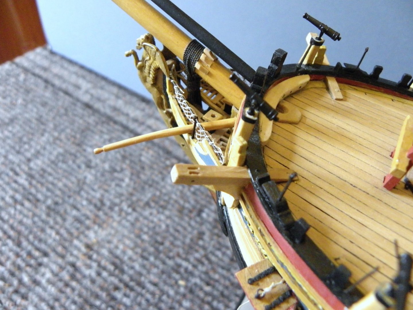
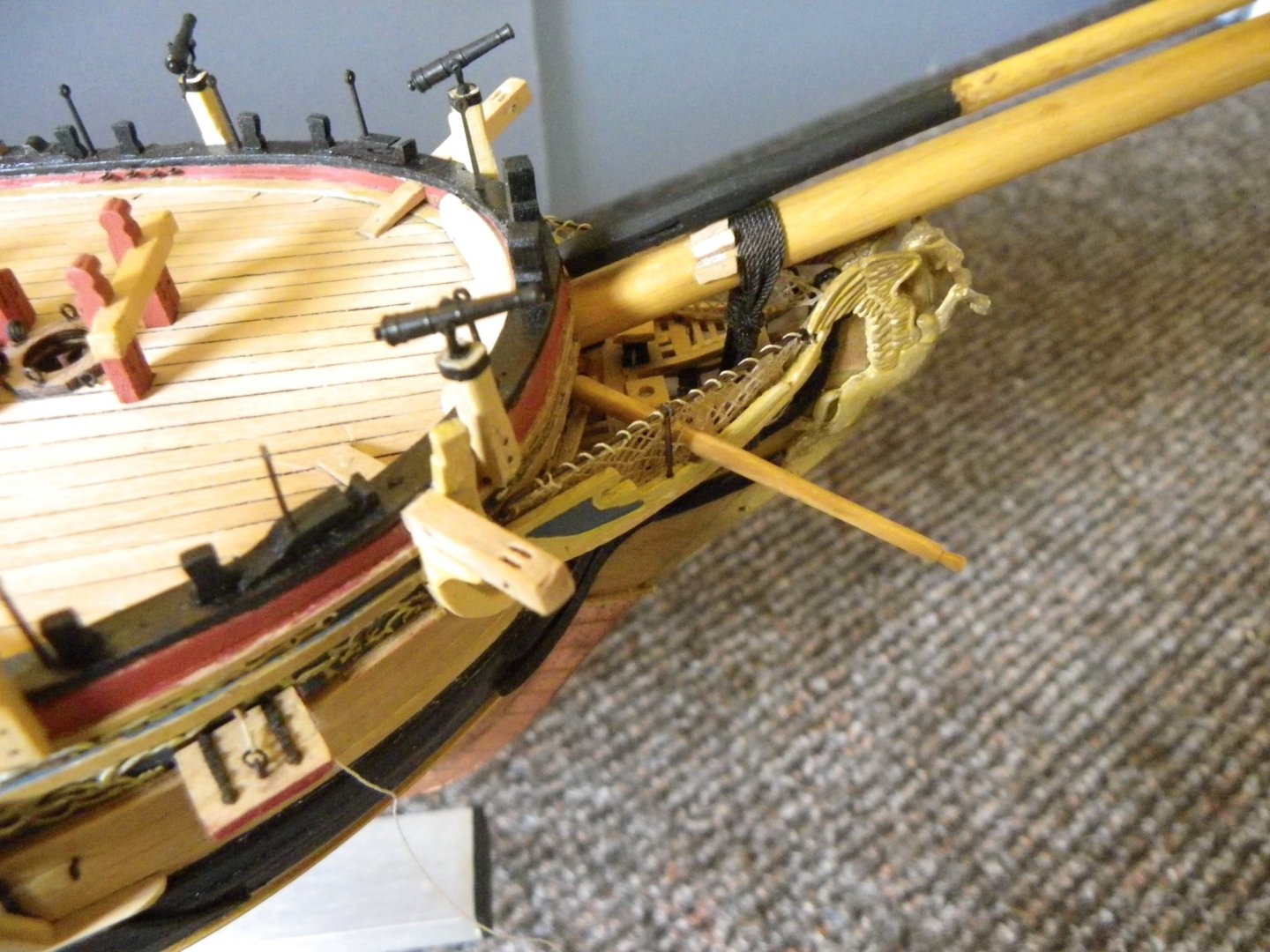
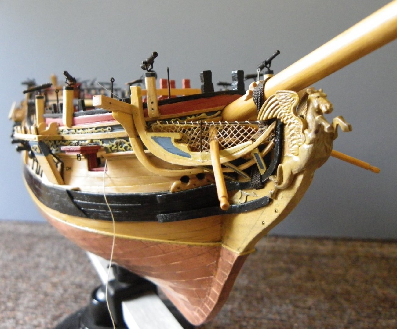
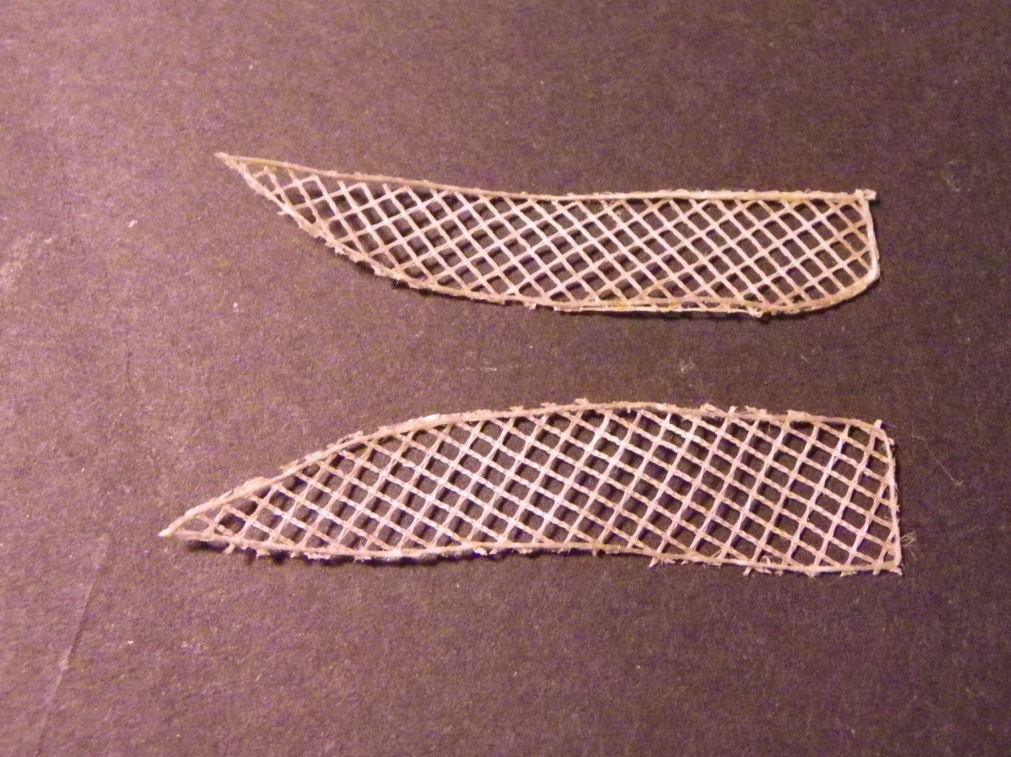
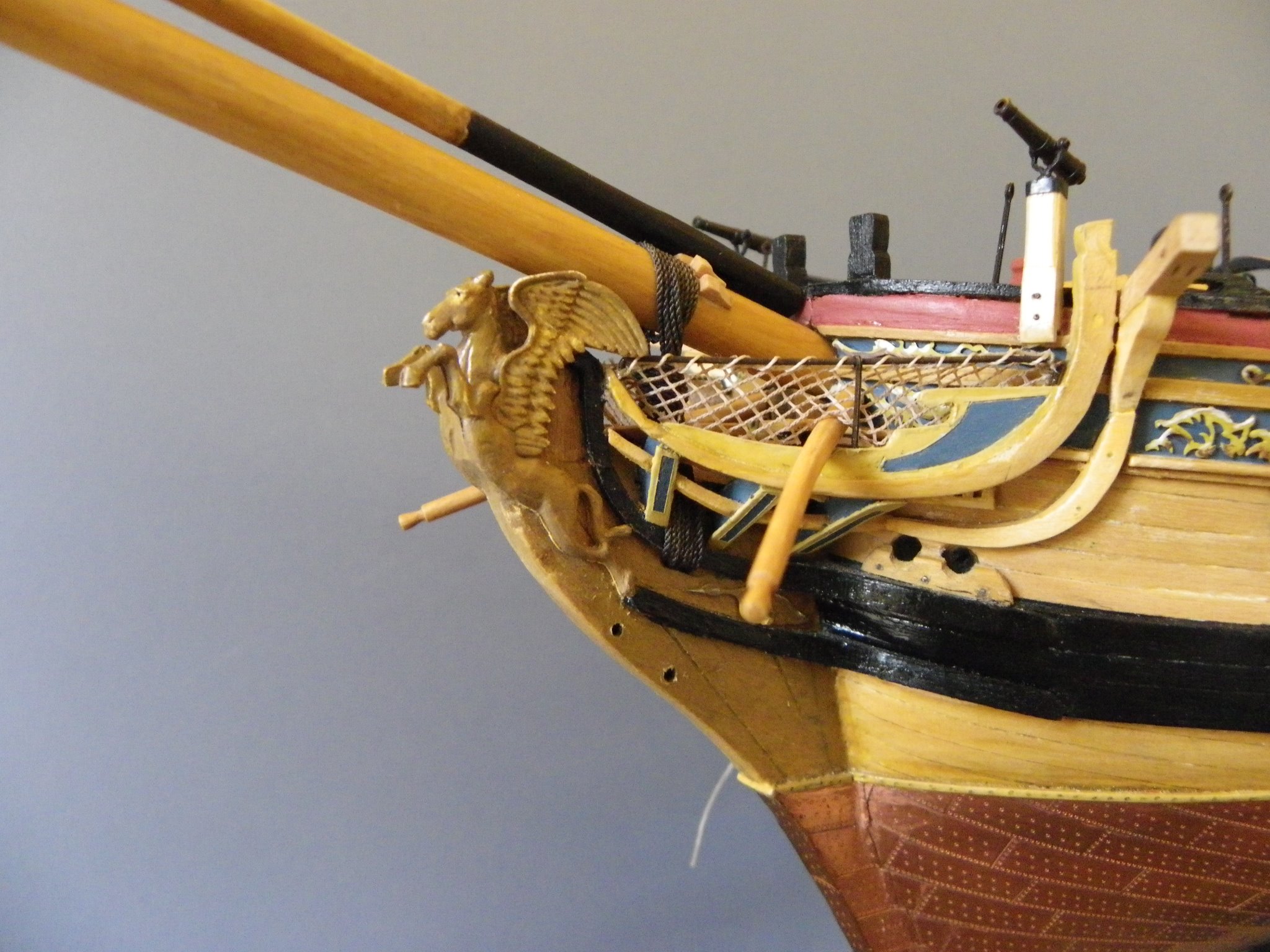
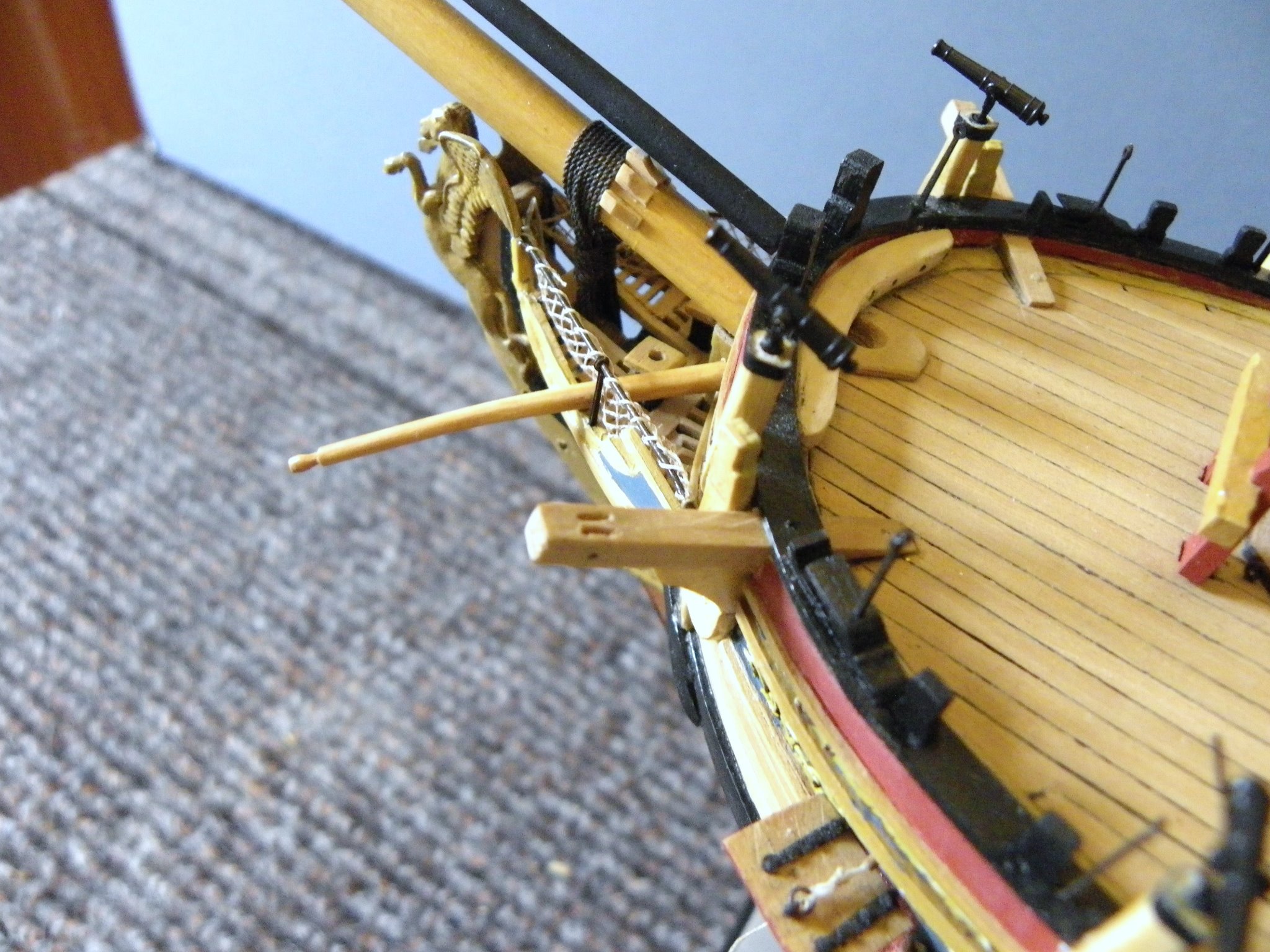
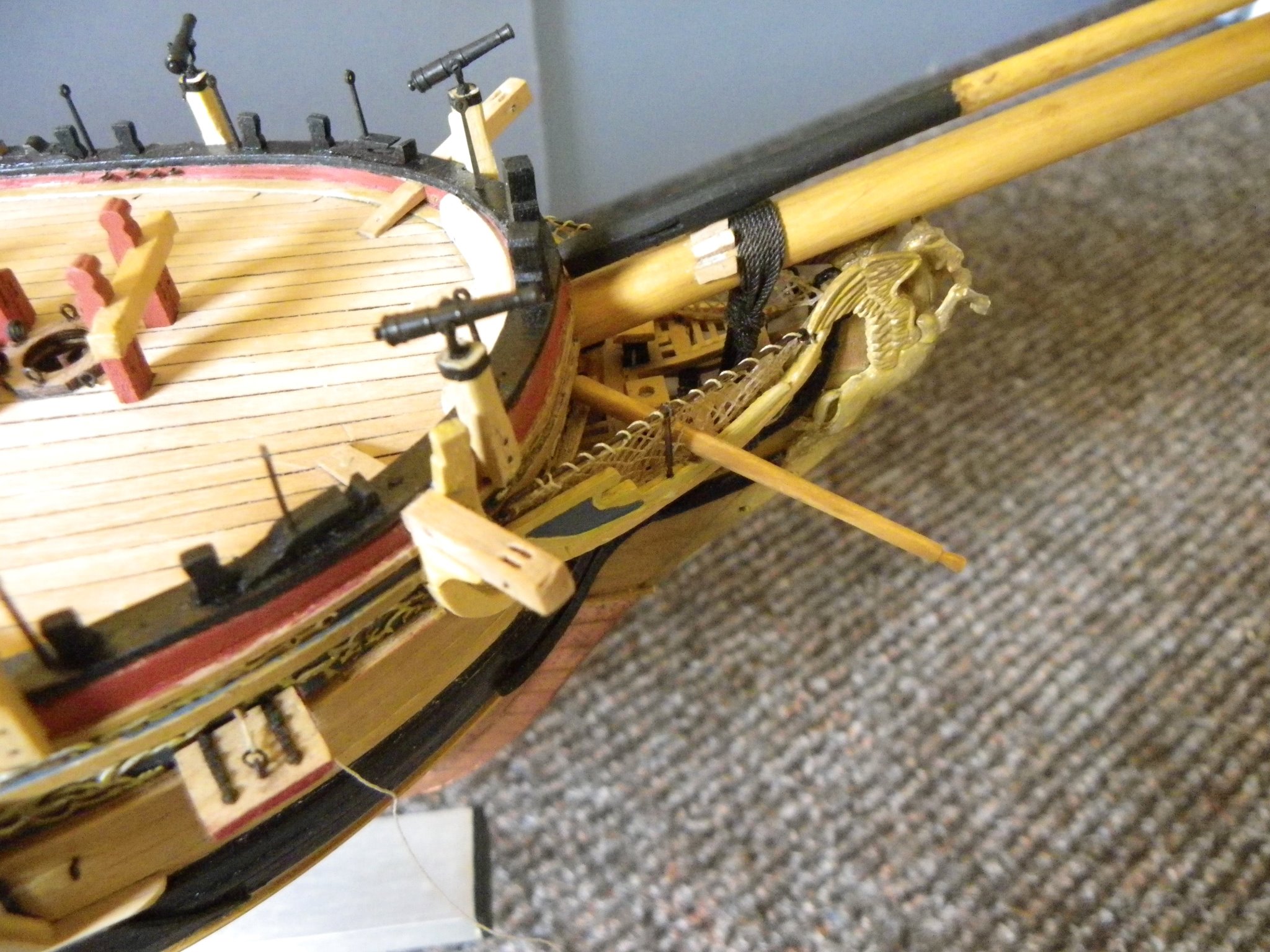
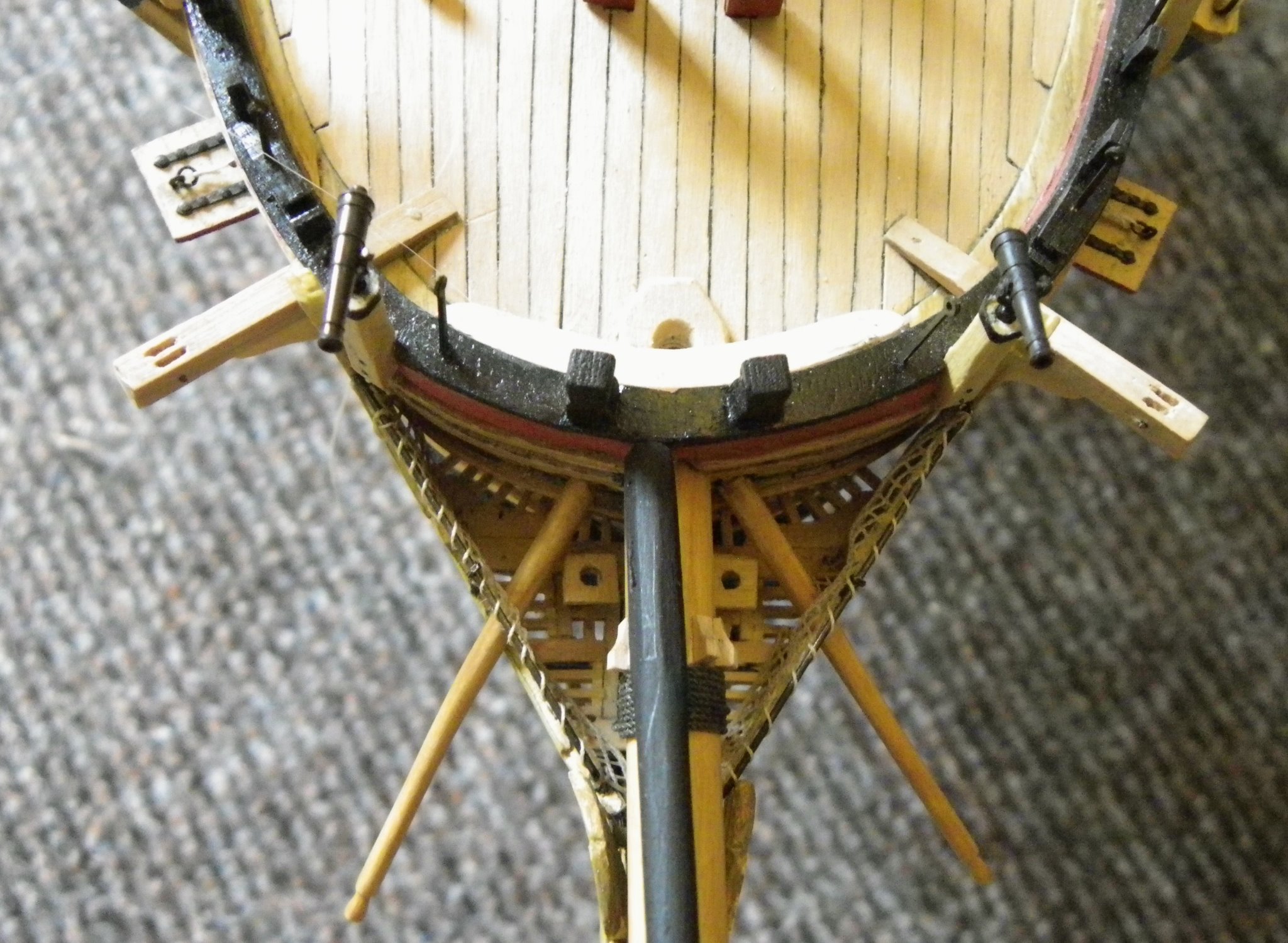
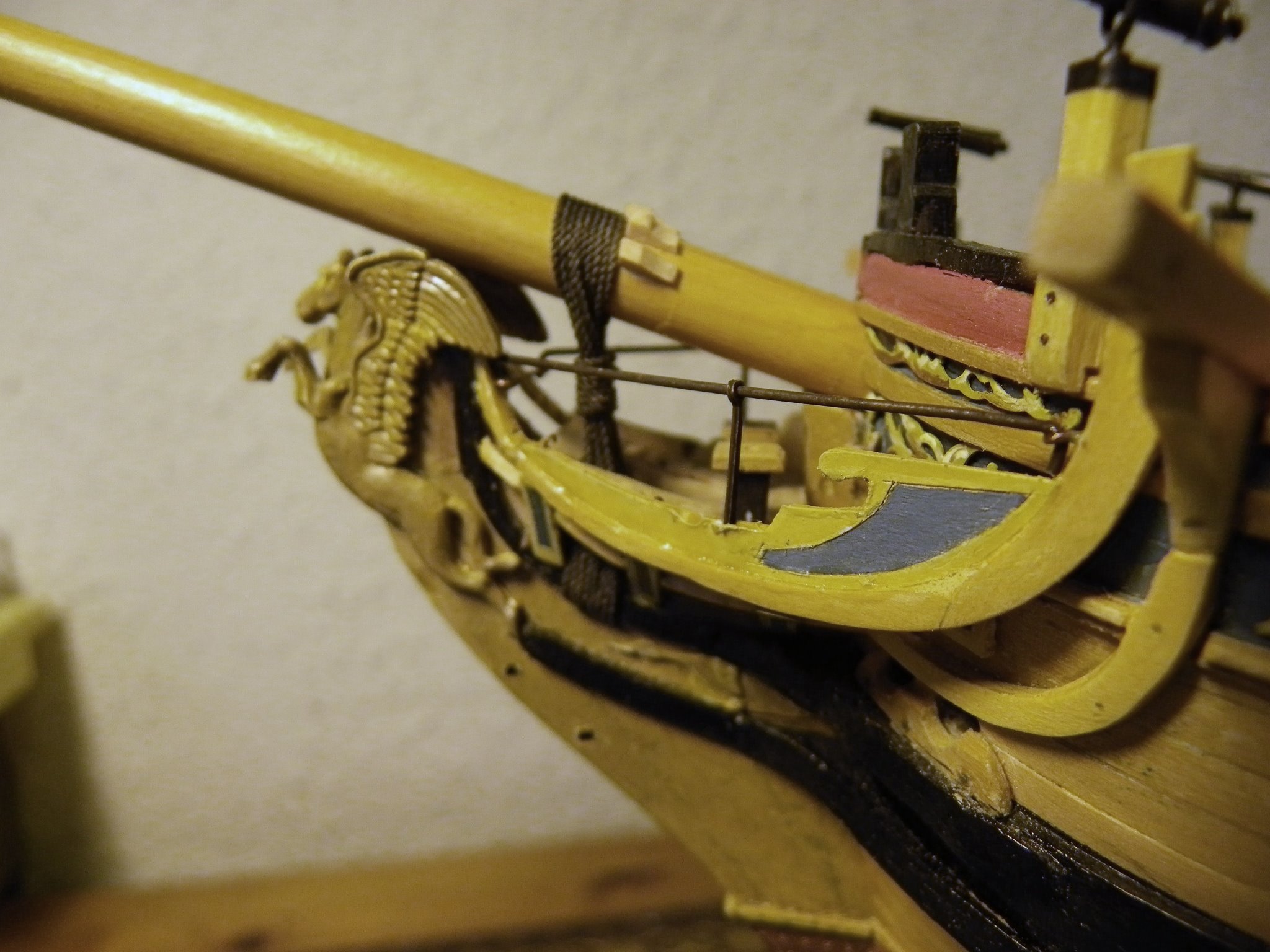
 Thank you Radmancoop, I'm pleased my log is of help, and I hope you are enjoying your Pegasus build. I've looked back through my files and below I have copied the section on the Bowsprit netting and set up. 09/02/015 Returning to the head With the Bowsprit fixed and the gammoning in place I can return to the head . 14 The Berthing rail and stanchion which provide a safety barrier can now be put into place. For the rail 0.7mm brass tubing is used. I had previously fixed the eyelets to take the rail and small hooks inside the False rail to hold the lower edge of the netting that completes the job. 26 For the netting I returned to my stock of old net curtain material which has 1mm square holes; cut on the diagonal it looks about right. Colron Light Oak wood dye was used to colour the netting, the dye was simply brushed across the netting both sides and allowed to dry. This produced a pale hempy colour similar to the running rigging scale hemp and to my eye gives a reasonable scale effect of untarred rope. The Boomkins Dimensions taken from Steel and made from 3mm dia dowel tapered down to 2mm. Outside of the False rail there is a curve in the spar, this was induced by firstly soaking and then curving over a suitable former. 30 69 48 51 60 Regards, B.E.


- 366 replies
-
- 5
-

-
- pegasus
- victory models
- (and 2 more)
-
Looking very nice Jason, some good 'fixes' there to get around making those tricky little fittings. The cutter is a great little addition to the deck, beautifully made. B.E.
- 800 replies
-
- 3
-
-
- snake
- caldercraft
- (and 1 more)
-
Cheers Guy's glad you like it. Post 35 Riding lamp completion Before I cleaned up and blackened the lamp I wanted to make sure I could fit the lamp glass. I did eventually settle on using a fine paintbrush cover, slightly opaque and of 3.5mm ø. Several attempts later I managed to get a 1.5mm slice of the tube that fitted snugly in the lamp. 8615(2) 8620(2) With the lamp ‘glass’ looking ok I could move onto the blackening. 8627(2) The glass was removed, and the body cleaned using micro files, fine wire wool, and acid, before immersing in the blackening fluid. 8640(2) Came out a lot better than I had dared hope, given the small size and delicate handling required during cleaning. 8637(3) 8634(2) Time to get back to the main event. B.E. 09/11/20
.thumb.JPG.d5c3e7432eb31eaa2eeca9c7177ca830.JPG)
.thumb.JPG.733cdf15cdb5fe5b060fb2453b61c978.JPG)
.thumb.JPG.e07c8c630c8f426b5cb3e13de74e5ebf.JPG)
.thumb.JPG.81e9b072aa200483a5817a9b3b34b3d1.JPG)
.thumb.JPG.44cdba8ecd9e2ba124e76abe0c418dfa.JPG)
.thumb.JPG.77caaa9a93eef02aeca47f418433ff43.JPG)
.thumb.JPG.51cf4d25959bcde8fa8a7ea98ca7eb62.JPG)
- 261 replies
-
- 21
-
-
- muirneag
- vanguard models
- (and 2 more)
-
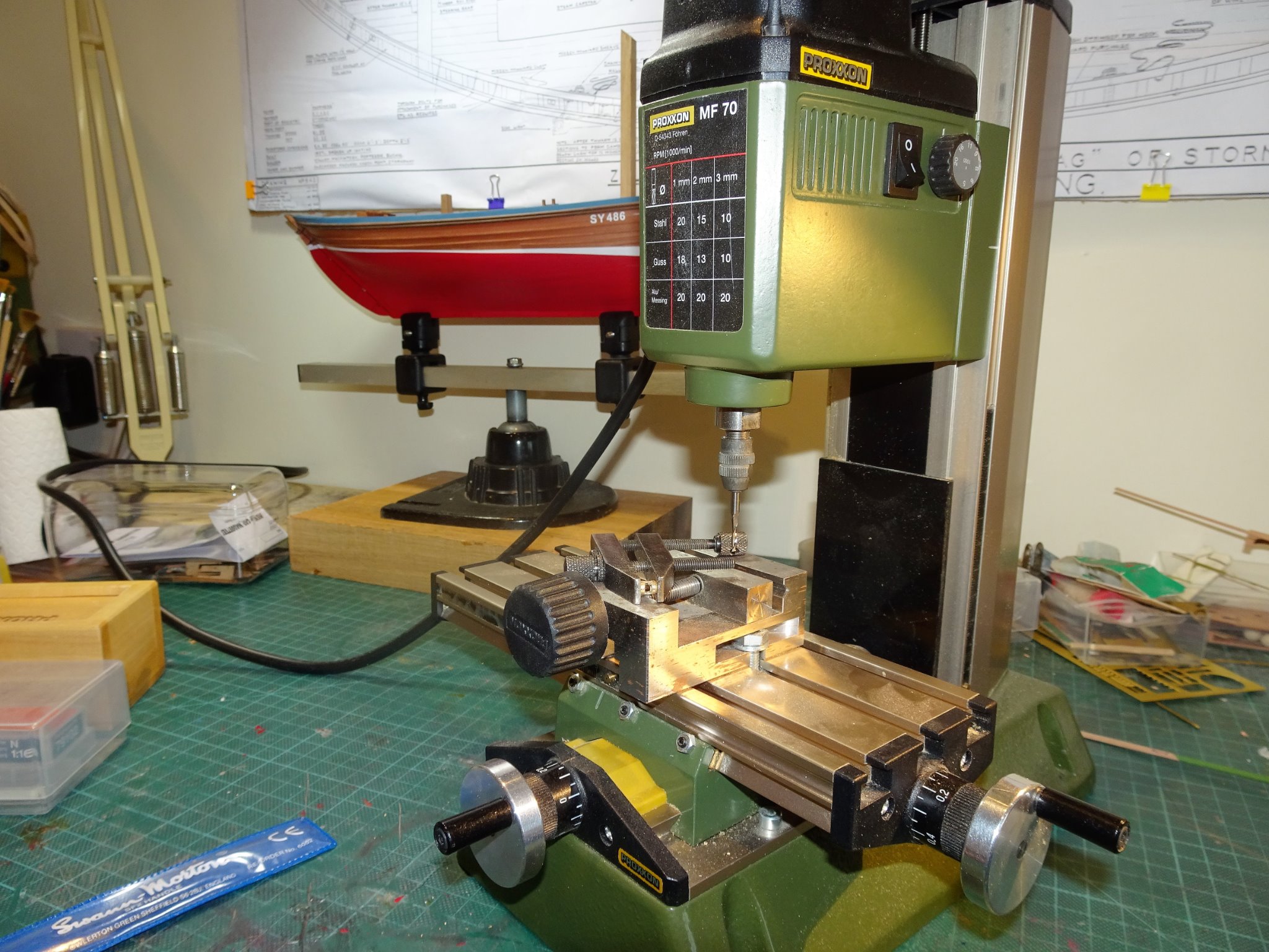
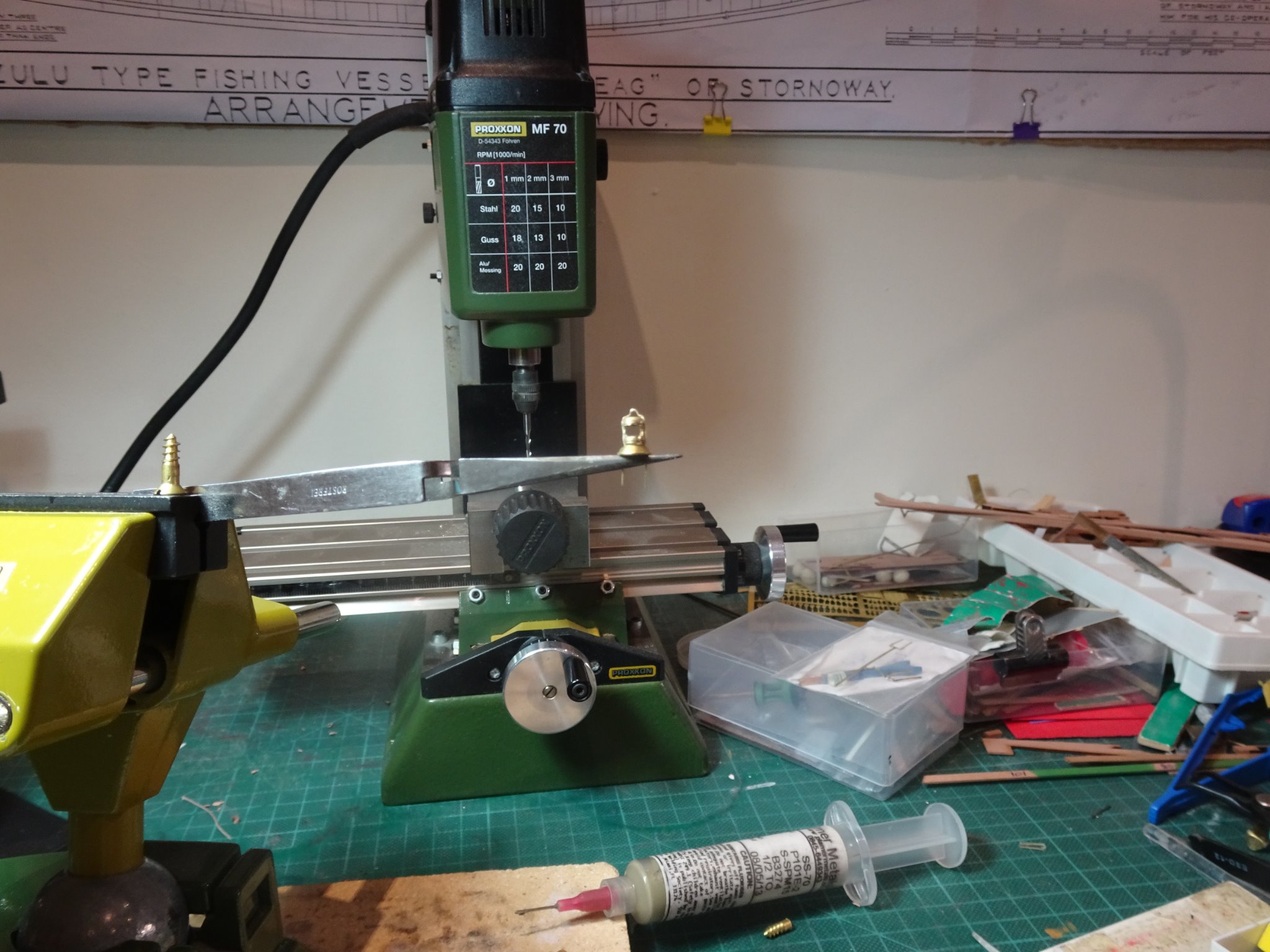
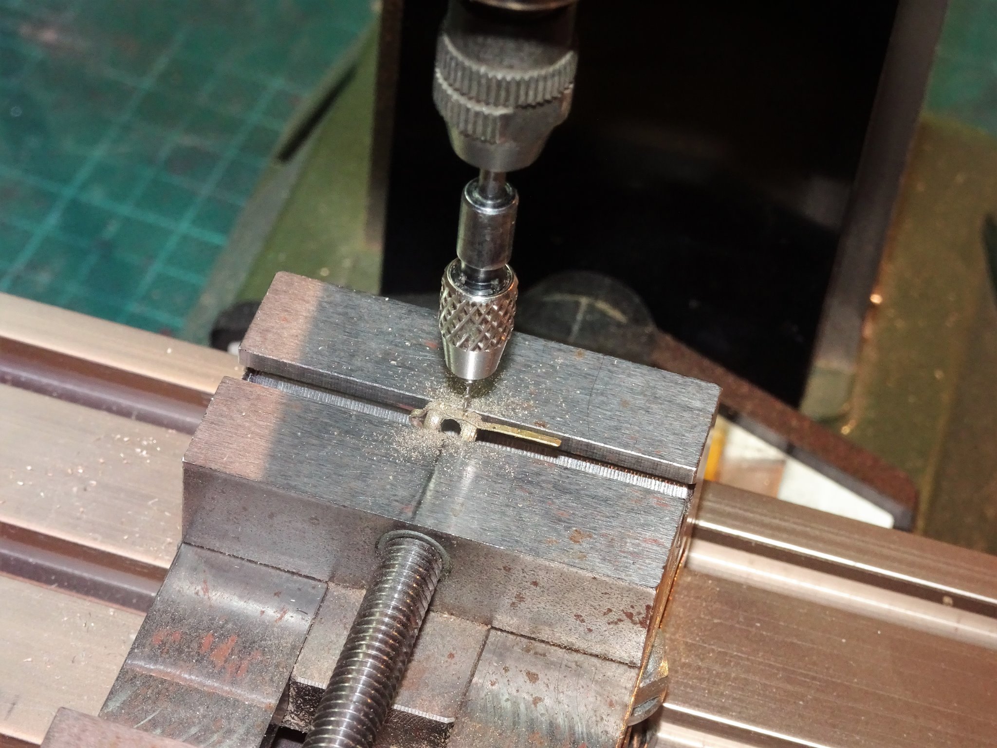
Post 34 Riding lamp Having made the Riding light stanchions I was committed to at least having a go at the lamp. The basis of the lamp is small brass Billing Boats masthead lamp bought from CMB. At (6x4mm) it was the smallest I could find and is a good fit for scale. 8565 To convert it to the riding light I first had to mill thro’ the back of the part to give a 360 degree light. The strap and top handle were then added using brass strip silver soldered to the sides. I use a high melt point (690 degrees) paste to allow for adding further items. 8580(2) 8586 Holes are drilled in the straps to take the retaining eyebolts. 8596(2) The eyebolts of necessity are very fine. I used Caldercraft etched versions of 0.25mm thickness with a 0.7mm ø hole. The danger in soldering these in place is that the flame may melt the eyebolt before the solder flash. A test piece was made before committing to the lamp. A lower temperature paste of 671 degrees was used for the eyebolts. I scratched my head for a while as to how to produce the shaped oil container at the base of the lamp. 8575 The answer came in the form of a small brass countersunk screw head. 8607(2) The completed lamp in its unfettled state fitted into its bracket. 8612 … and as would be used onboard, final height yet to be determined. 8610(2) The final hurdle is how to represent the clear glass cover of the lamp. My first thought was a section of one of those clear plastic covers that protect fine paintbrushes. Ideally a clear cover would be inserted thro’ the hole in the bottom of the casing, but when it came to soldering the base on, the obvious would occur. I have one or two ideas about creating the ‘glass’, but the subject bears more thinking about before I commit. It has been interesting making this little ‘extra’ if only as an exercise in silver soldering tiny parts. Still the finishing to do but I’ve rather enjoyed the process thus far. B.E. 09/11/20

.thumb.JPG.6acfbe81036279413d0f2b86d34df5f2.JPG)

.thumb.JPG.b35834059d3437bbee8497aa2956dce4.JPG)
.thumb.JPG.60ec362afab2284549338e9c4bc4014a.JPG)
.thumb.JPG.156f5d6a51a1917e04d5040e05473885.JPG)

- 261 replies
-
- 13
-
-
- muirneag
- vanguard models
- (and 2 more)
-
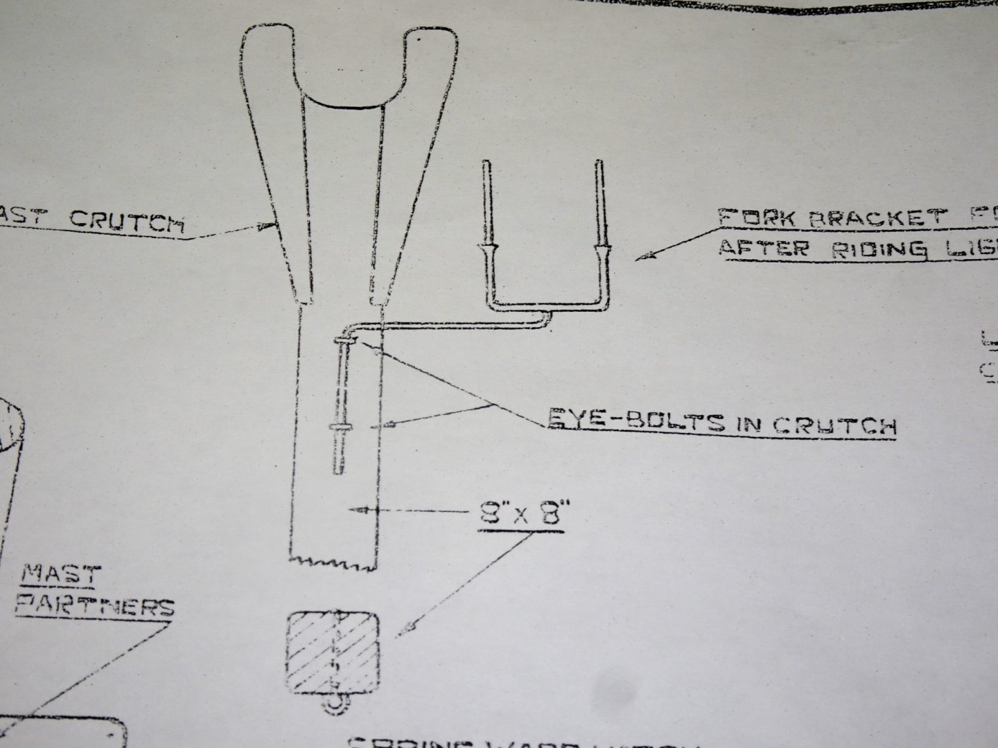
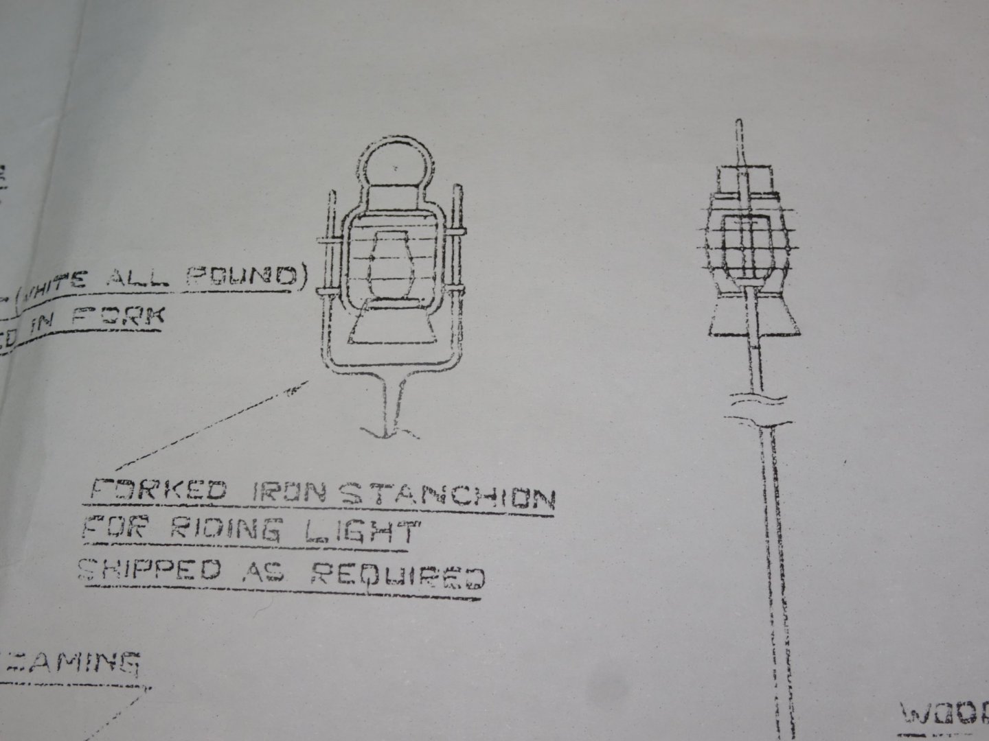
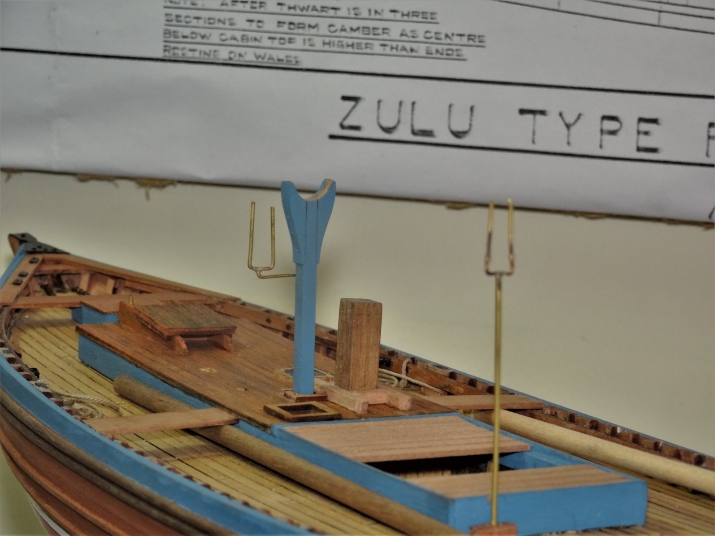
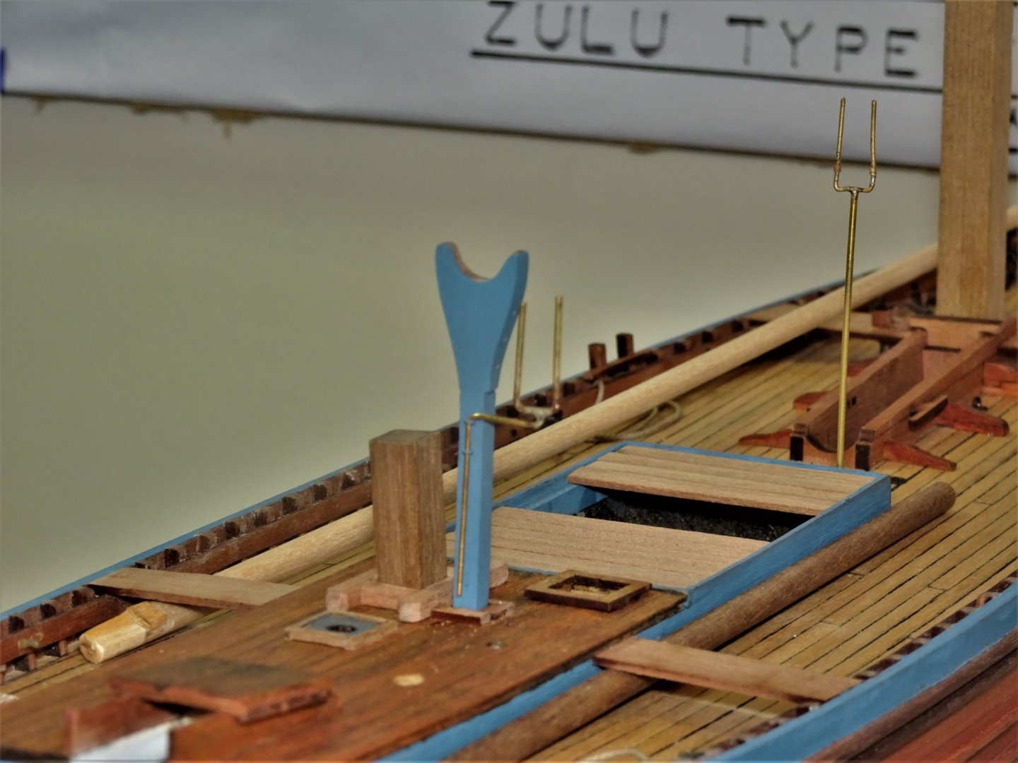
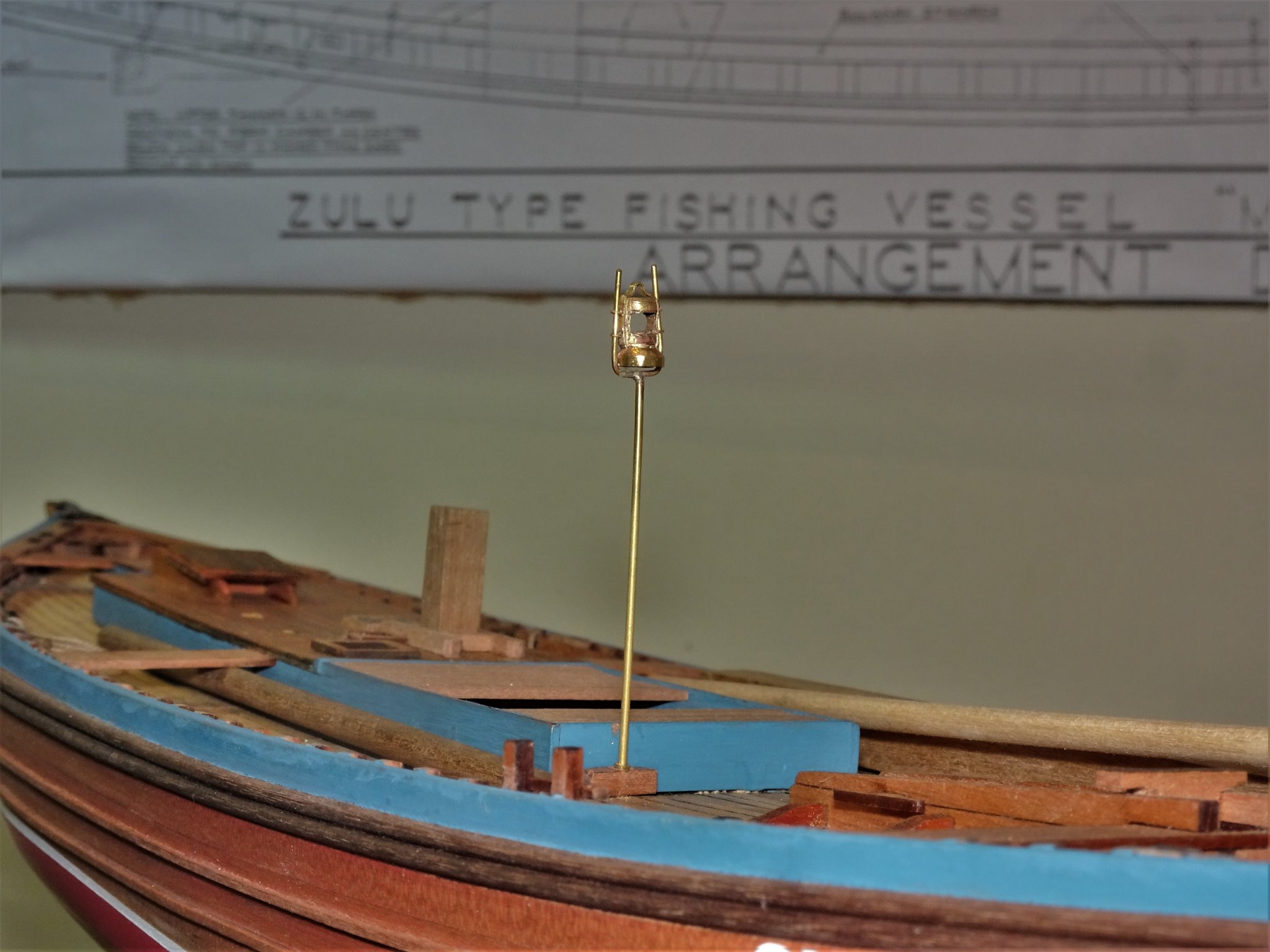
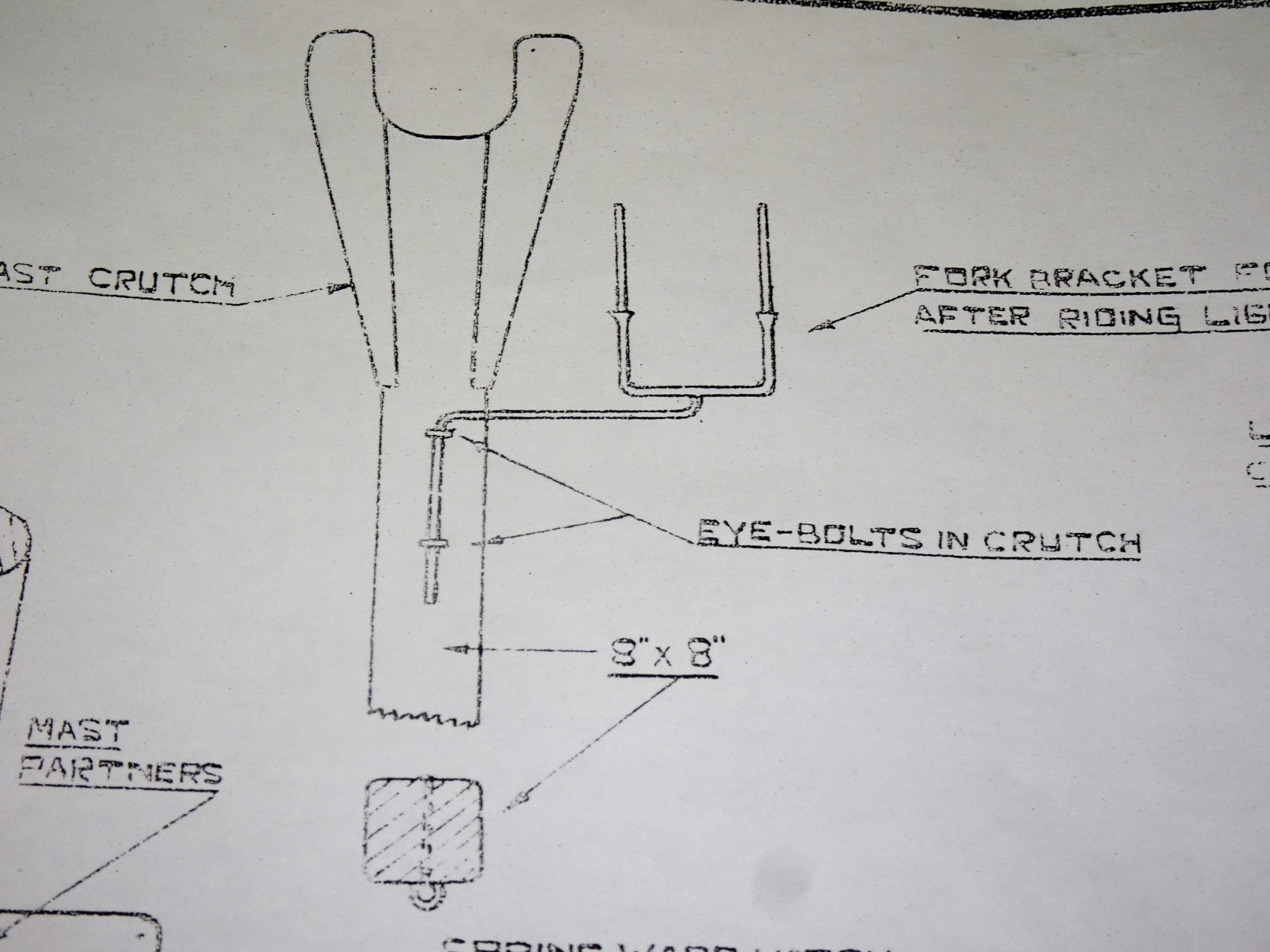
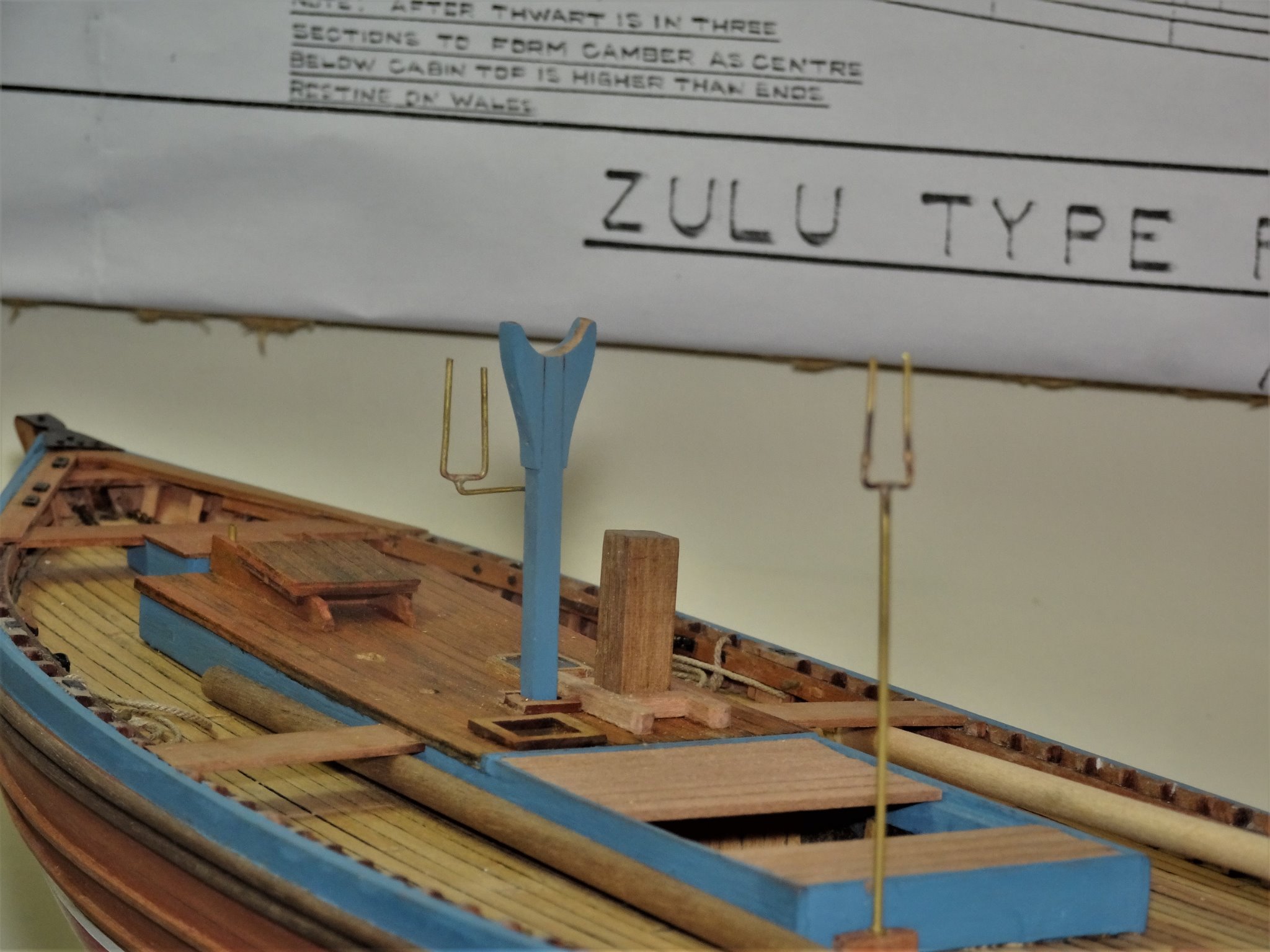
Thank you Thomas, here's a few more. 😉 Post 33 I can’t quite decide what to do next on the build so I decided to play around with some optional fittings, namely the riding lights. I suspect that these lights were only used during fishing when the boat was drifting, mast and sails lowered. 8549 The aft riding light slots into brackets on the aft side of the mast crutch. 8538(2) 8542 Not too difficult to construct with brass tubing, wire, and a spot of silver soldering. 8562 Will be trimmed to size once I have sorted out the lamp. The forward light sits in a similar forked stanchion that fits in a socket set against the forward coaming of the fish hatch. 8550 8559 8558(2) That is the easy bit, what to do about the lamps is the tricky part. At scale these hurricane style lamps are a mere 6mm high x 3.5mm wide. 🤔 B.E. 06/11/20
.thumb.JPG.e3ccd70a30fd68e71e89f7dae9d2975c.JPG)
.thumb.JPG.c371426816a25b640850125ba9c87656.JPG)
.thumb.JPG.cd2026c1886a0239d354d12d006dc244.JPG)
- 261 replies
-
- 14
-
-
- muirneag
- vanguard models
- (and 2 more)
-
Cheers Guys, @ John - do you have the name of the village your Great Grandmother lived in, I may have some references to it in my reference books. B.E.
- 261 replies
-
- 1
-
-
- muirneag
- vanguard models
- (and 2 more)
-
A fine job Richard, would even work as a single layer hull in other circumstances. 👍 B.E.
-
I like the look of her Richard, I think you have got the look of a working boat spot on. 👍 Those little pearwood 'triangles' look suspiciously like yard cleats, may come in use on other builds, I don't recall seeing them either. 🤔 Re the capstan - I don't tend to glue down deck fittings if I don't have to; easier to clean the model if they can be removed. Regards, B.E.
- 49 replies
-
- 2
-
-
- Lady Eleanor
- Vanguard Models
- (and 1 more)
-
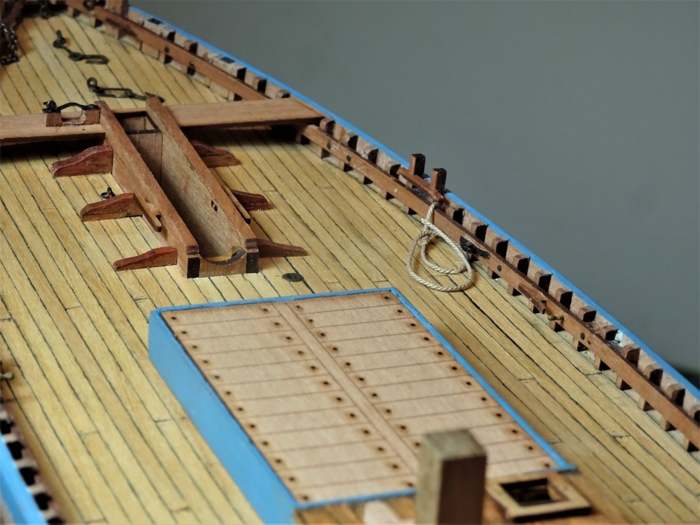
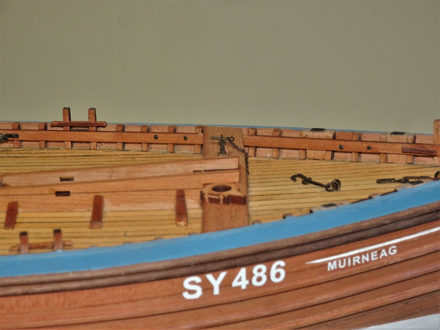
Thank you Glenn, Erik, and John. @ Glenn - The losses suffered by those small fishing communities make for sobering reading. In one notable storm in October 1881 189 men were lost, 129 from one community leaving 263 children fatherless. No social security in those days. The possibility is real that many of the boats lost were rendered unmanageable owing to crews being weakened through men washed overboard. Losses overboard were an ever present danger. @ Erik - I think I'll leave the stem plate unpainted, I do like the look of blackened metal. @ John - Coming from an old salt like you, that's good to know. 😀 Post 32 Bobstay sheave Situated on the starboard side of the stem is a sheave to carry the Bobstay. The kit provides a simplified etched piece (PE11) referred to as a stem cleat. I replaced it with a scratched version based on the Underhill drawings. 8487(2) 8493(2) Silver soldered together from thin brass strip and micro tubing. 8504 8501 8507 Competed and chemically blackened. 8512(2) In checking over the inboard fittings I realised I had forgotten to make the Mizen halyard sheaves so two of these were made in the same fashion as the Bobstay sheave. Rope stopper The Underhill plan shows these lines spliced around the stringers both port & starboard ahead of the Fore and Mizen halyard sheaves. 8532 In use they are bent to the falls of purchase with a rolling or stopper hitch and take the strain while the running end of the fall is taken off the capstan and belayed to the cleat. 8515 In the absence of any other information I have used Syren 0.63mm ø line. which looked about right to my eye. 8529 Not an anchor chain but the Bowsprit necklace chain that will be trimmed to length once the Bowsprit is fitted. 8535 All the Foredeck fittings are now in place. B.E. 04/11/20
.thumb.JPG.182764207b4085c2efabf624f6b5f11b.JPG)
.thumb.JPG.4ead96ba36791fdf7240760214598698.JPG)


.thumb.JPG.90df183478357a3073a54d7fceee84ae.JPG)


- 261 replies
-
- 17
-
-
- muirneag
- vanguard models
- (and 2 more)
-
Love the look of those little carronades Glenn, nice work. B.E.
- 778 replies
-
- 2
-
-
- cheerful
- Syren Ship Model Company
- (and 1 more)
-
Seamanship in the age of sail is an excellent choice. 👍 B.E.
-
That's a very tall order. There are books on specific ships, books on specific ship types, books on specific periods, books on specific aspects - rigging, construction, arming and fitting etc, but all in one volume with great detail, I don't know of one. B.E.
-
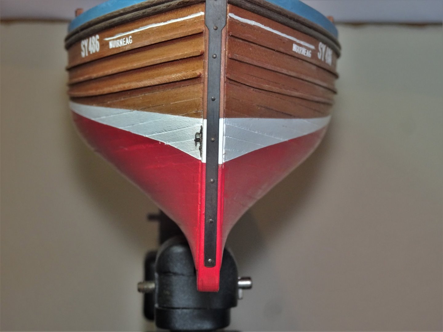
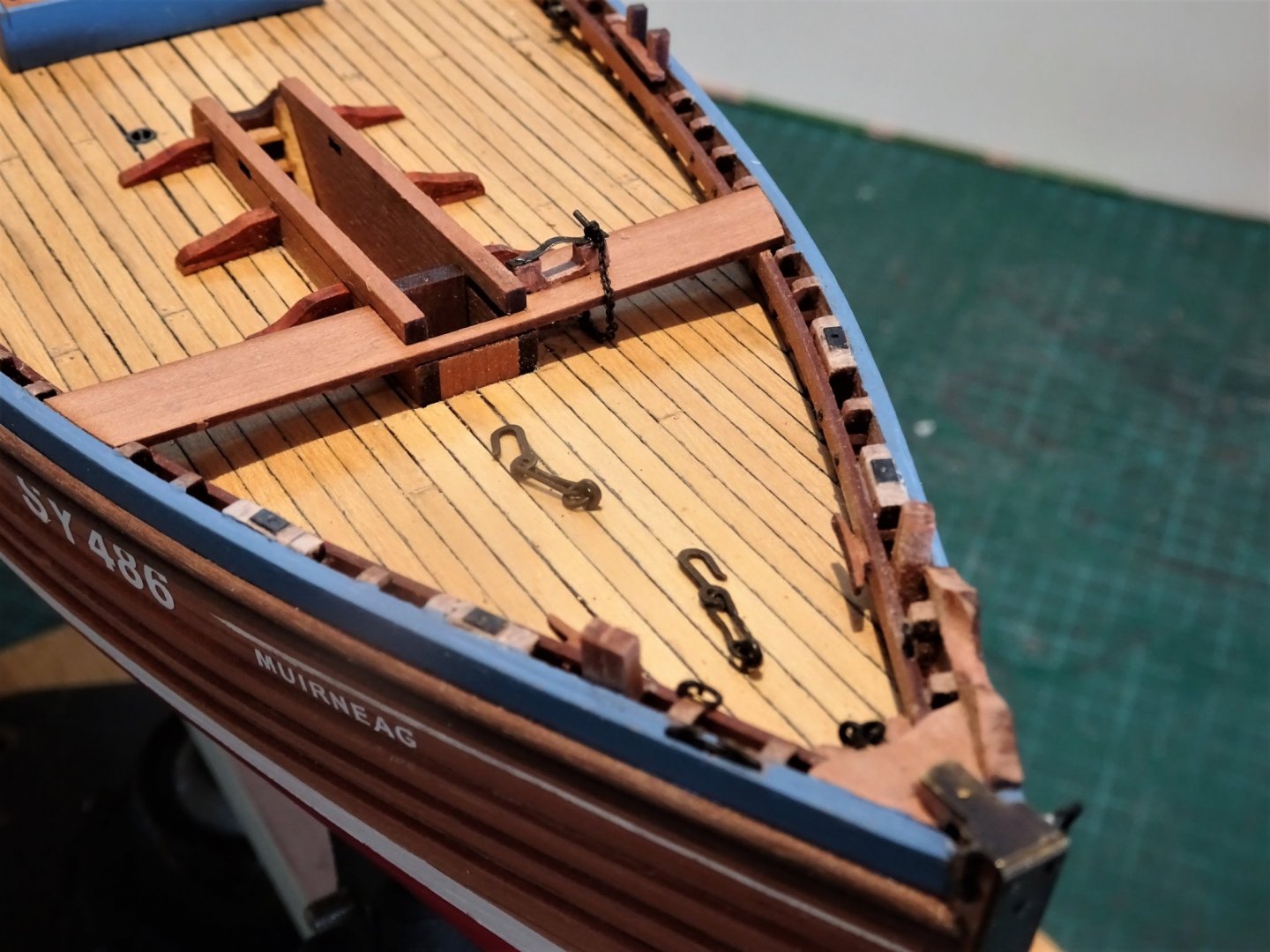
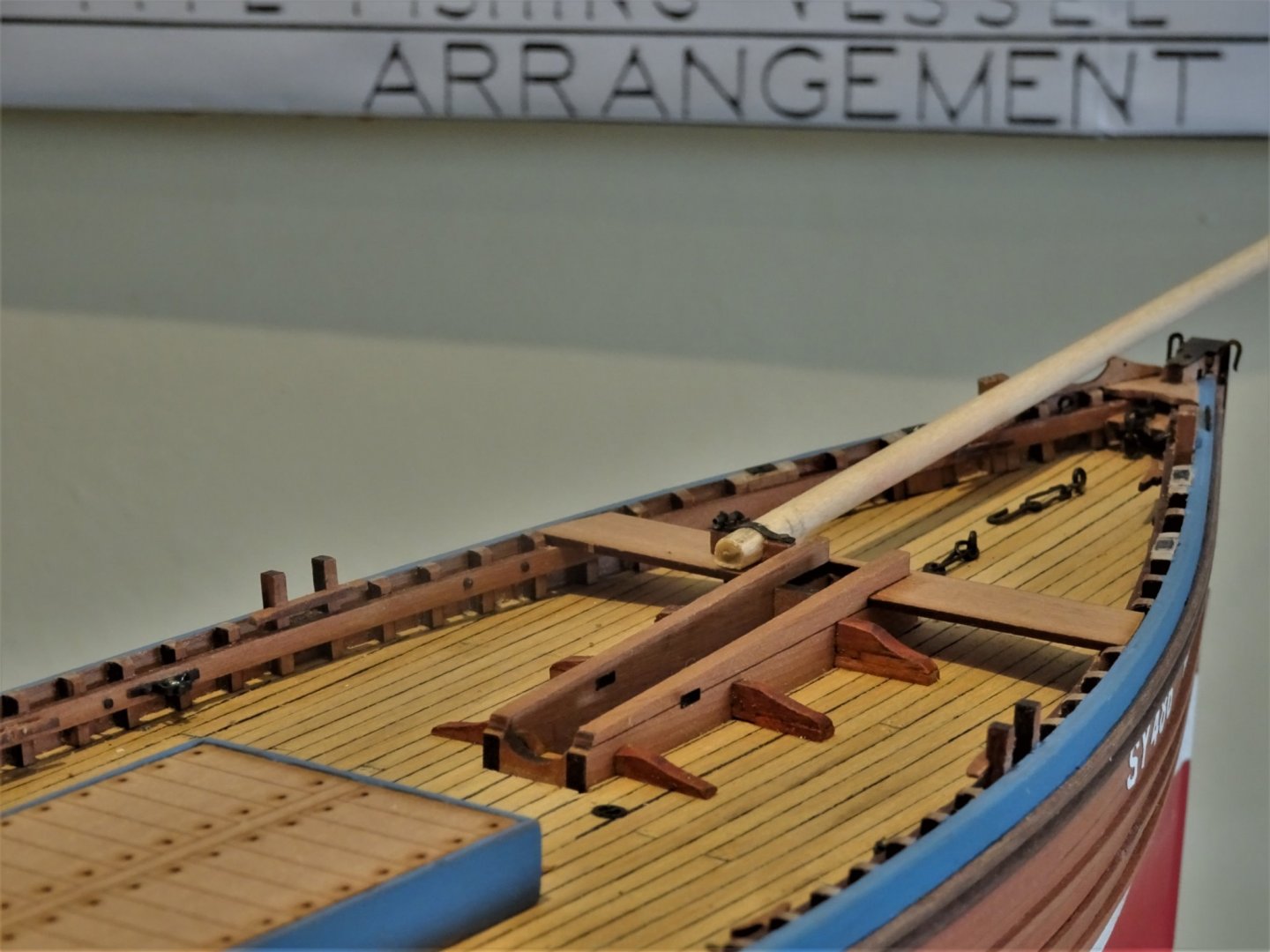
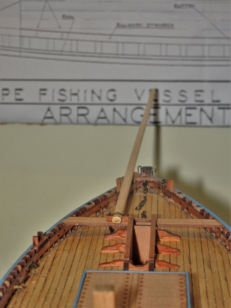
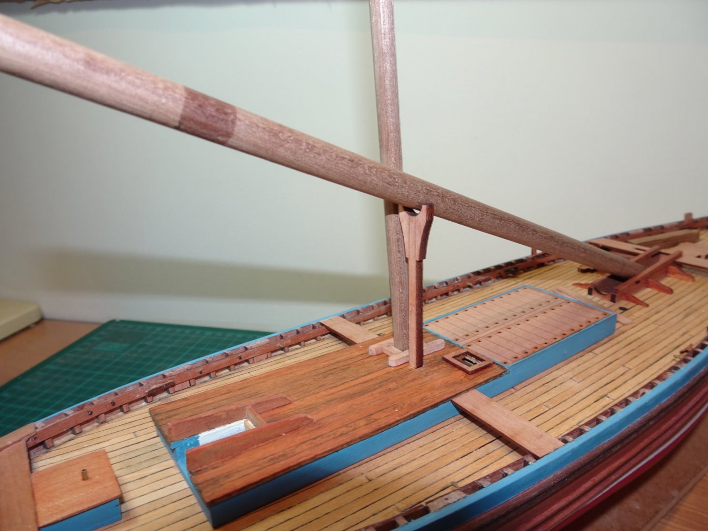
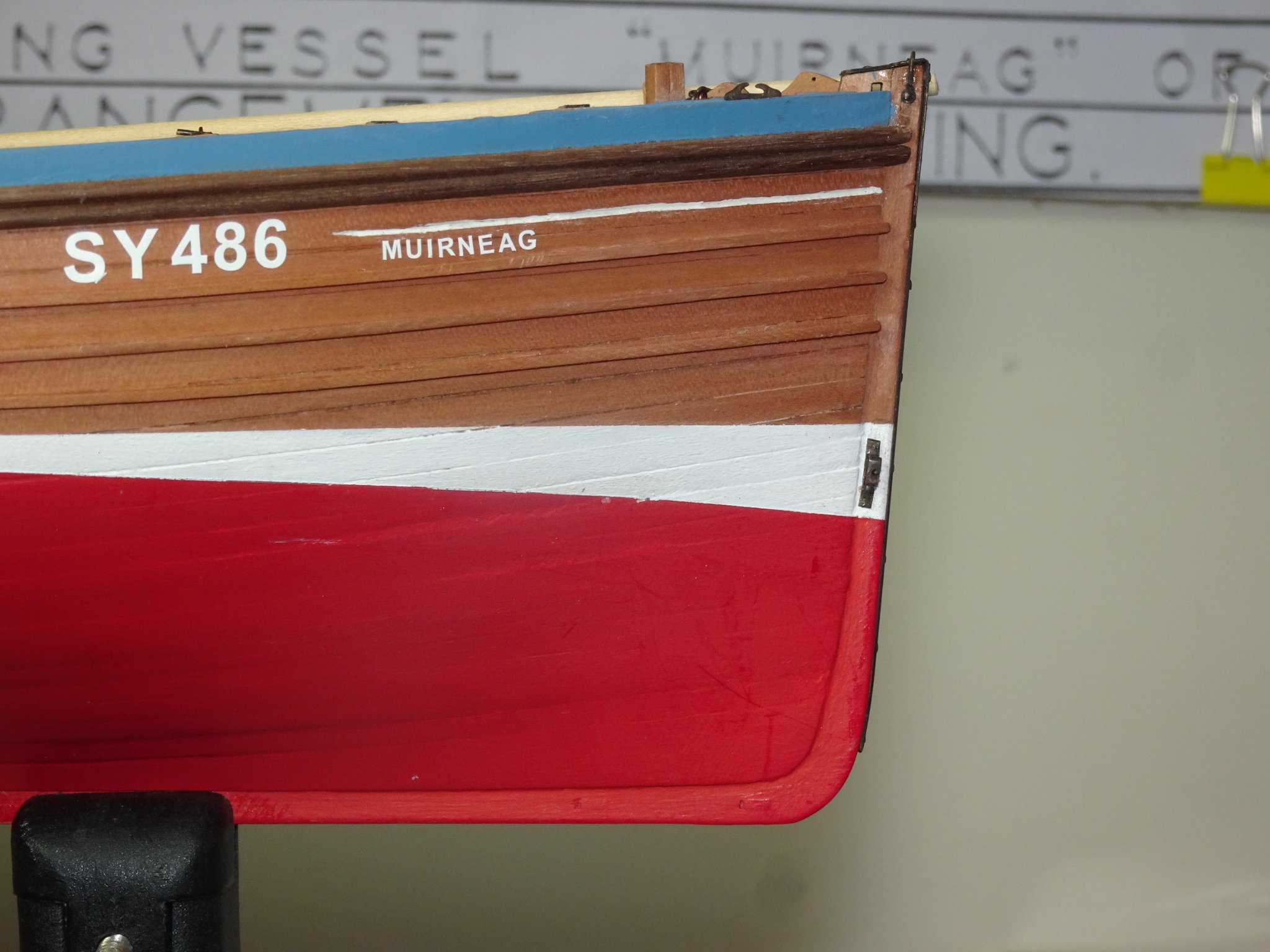
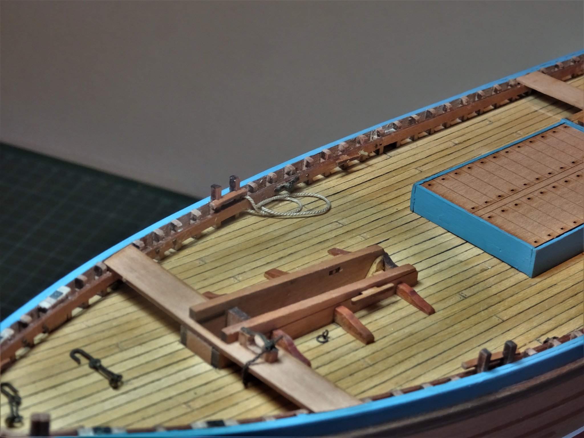
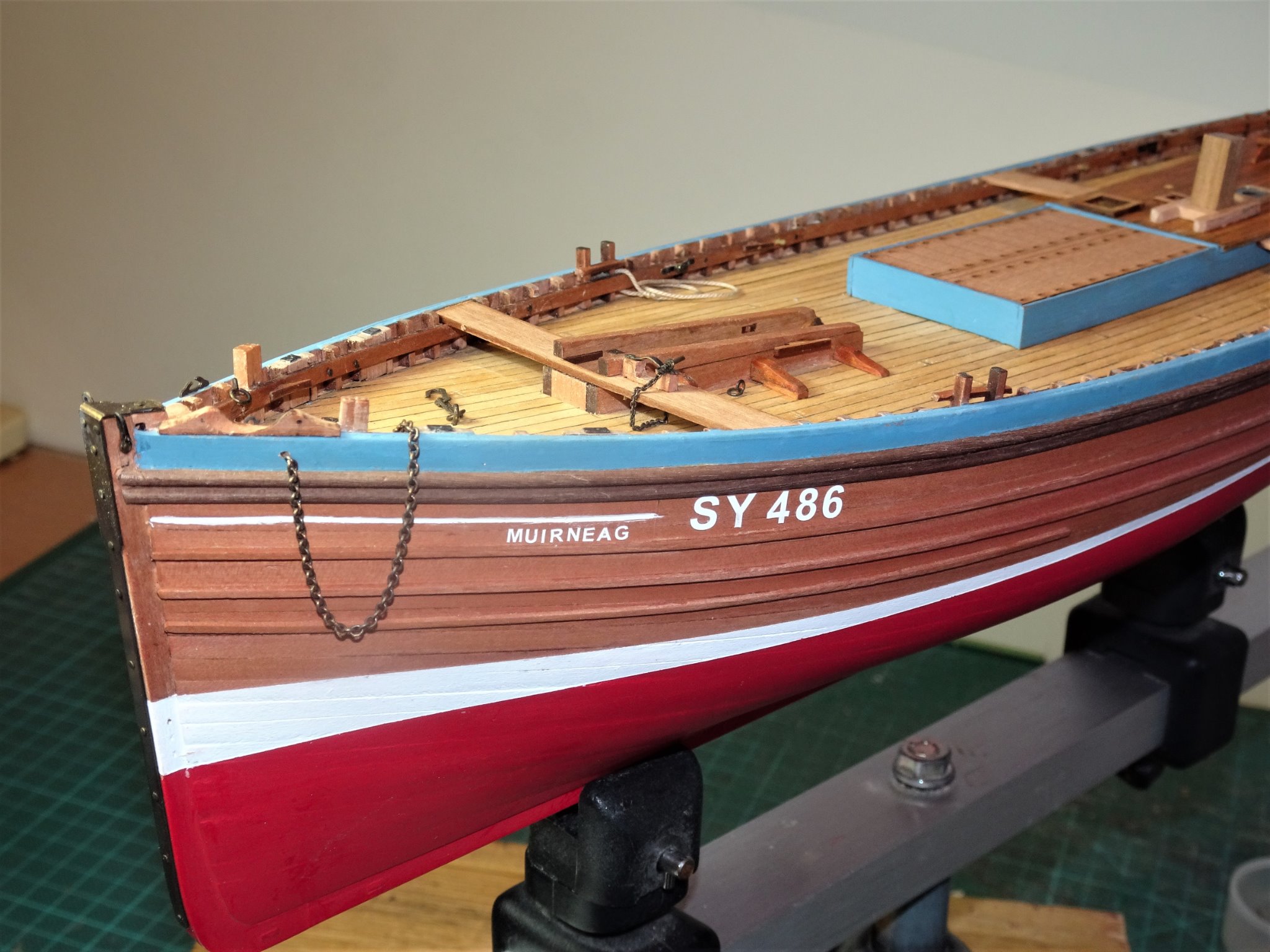
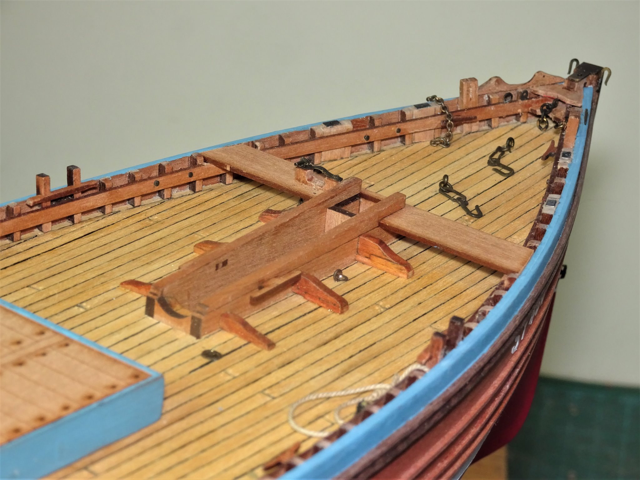
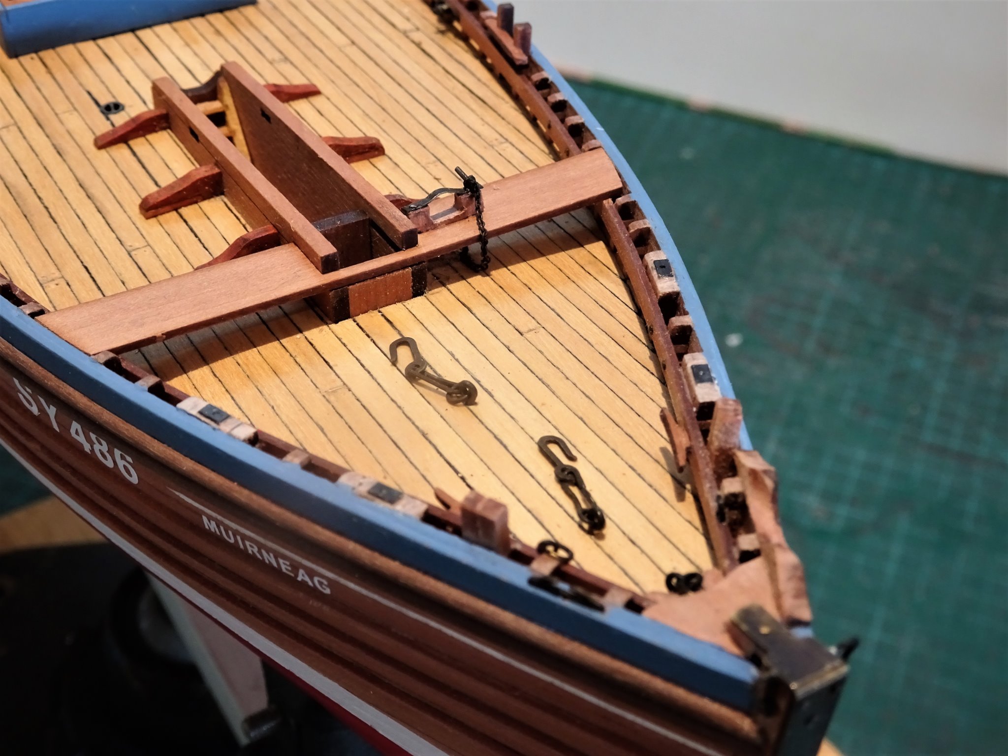
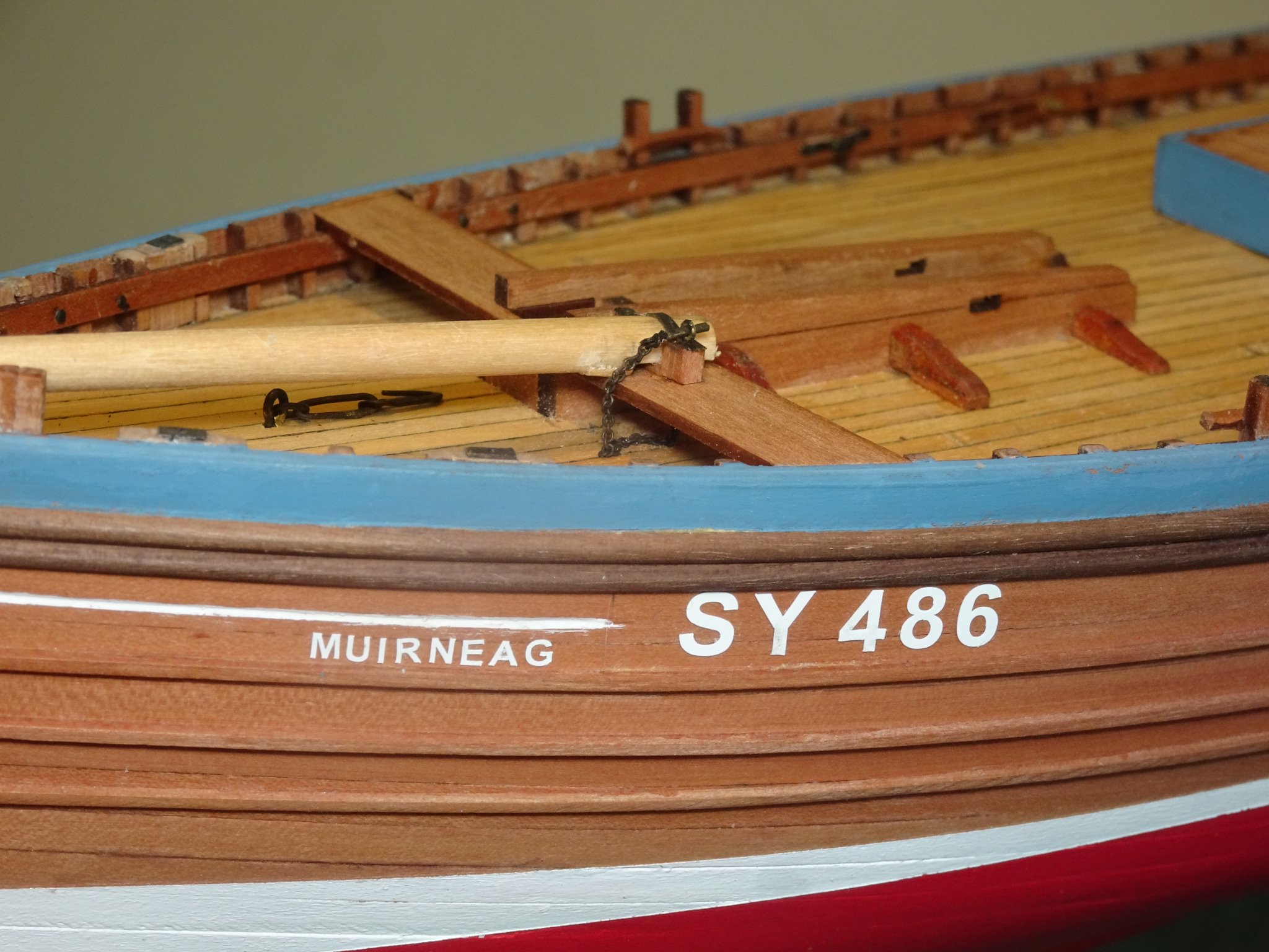
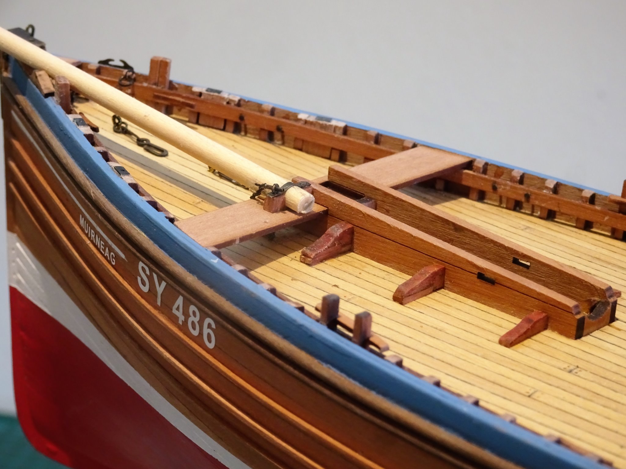
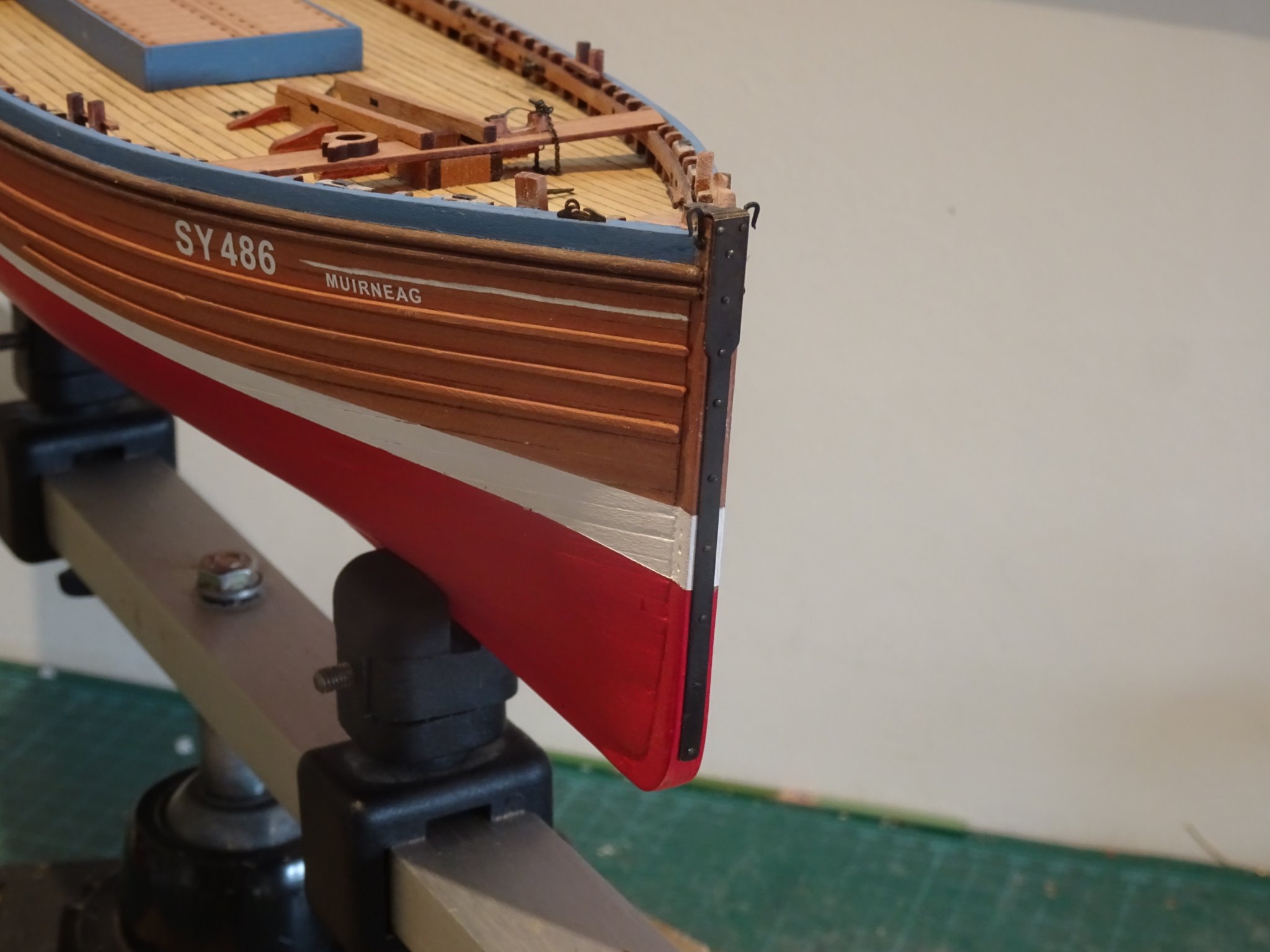
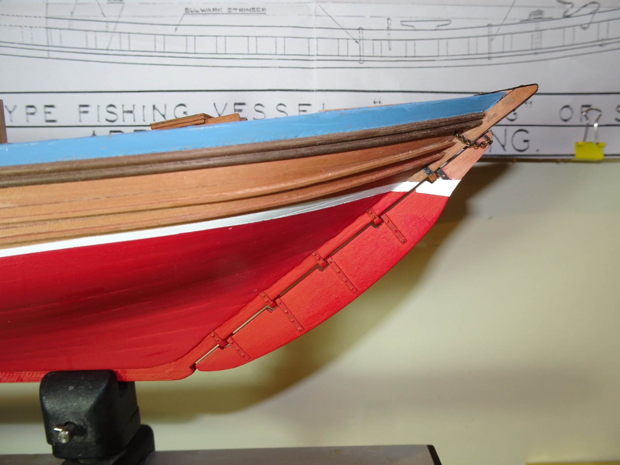
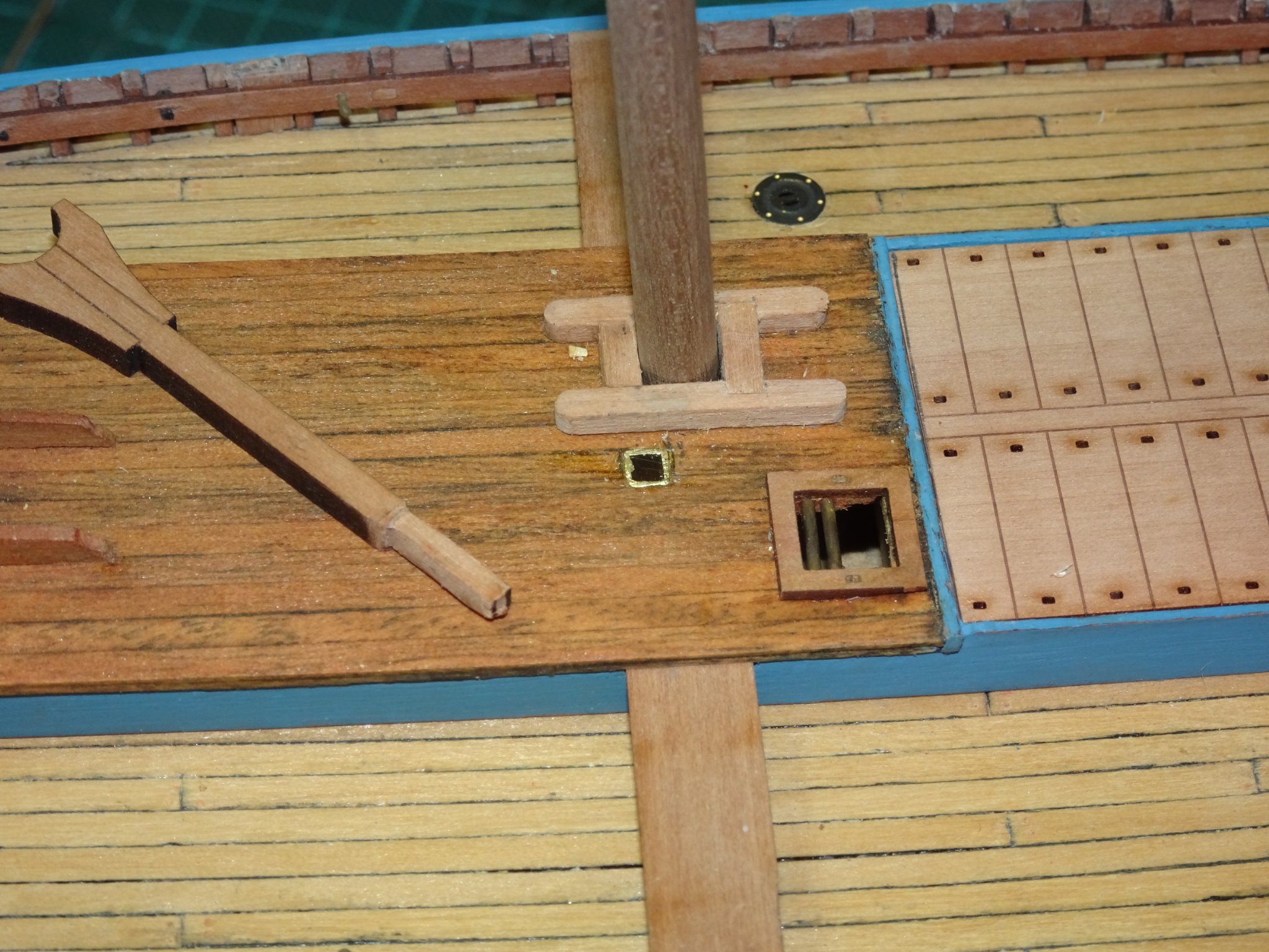
Post 31 Fore thwart, and Bowsprit fitting. The kit provides a laser cut Pearwood bracket that slots into the thwart to hold the Bowsprit heel. There are differences between the kit, Underhill plans, and the set up on other models and plans, that I need to resolve. I first need to check the comparative differences in the size of the spar. The kit has a 52’ length, Underhill 49.0’ The inboard ø 10” outboard 7.5” (kit) 12” and 7” (Underhill) These differences are of little consequence in the scheme of things. The Underhill plans and the models by Gordon Williams, Jan van den Heuvel, and the George Macleod model in the NMM show the Bowsprit heel cut to produce a shoulder which sits against the thwart. This is not universally the case as the plan of Fidelity shows a fully rounded bowsprit passing thro’ the bracket. In considering the set-up of the Bowsprit, the position and shape of the saddle needs to be considered. This is set up on the port side bow and as the spar crosses the saddle at an angle, final shaping can only be done insitu. I have replaced the provided bracket with a version that allows for an iron securing strap to be put in place. 8452 The arrangement is very similar to the cap squares used on 18thc guns to secure the trunnions to the carriage. 8480 The Fore tack deck hooks are also in place. 8466 8469 A temporary bowsprit has been made to act as a template to shape the saddle and form the iron. 8474 8476 8471(2) Quite sticky out the Bowsprit, but it could be displayed taken inboard. At this point I have also attached the Bow plate. This is provided in the kit as a nicely formed etched part. This was chemically blackened and buffed. The manual suggests that this part be glued to the stem and that short pins be inserted in shallow holes to represent the retaining nails. I didn’t find this necessary and simply pinned the bow plate to the stem using blackened pins only. (shortened pins for the top two) I was conscious of the fact that any stray ca getting on the Bow plate would spoil the look. The top of the plate did need a spot of ca to hold it secure to the stem top before the bolt is inserted. 8482 Attached to the sides of the stem can be seen the ‘Horns’ to take the Fore tack, this is a common feature on both Fifie’s and Zulu’s. 8454(2) At some point I will need to decide whether to paint the lower part of the plate in the colours of the lower hull, as I did with the Fifie. 8464 Still some tidying up to do on the deck and I need to decide whether to add the irons along the keel and a bilge keel. B.E. 02/11/20
.thumb.JPG.e7393895a083059245f9003f5ac5f228.JPG)


.thumb.JPG.2e2f927f685c8455e88ce73d692c671f.JPG)

- 261 replies
-
- 8
-
-
- muirneag
- vanguard models
- (and 2 more)
-
We’re of the same mind Richard, I didn’t know what either a Fifie or a ‘nautical’ Zulu were a few months ago. It is the research, the background, and history that is an important part and pleasure of any build I do. I now have seven books on fishing boats and I harbour a hope that Chris may add to his ‘fishing’ fleet one of the English iconic vessels. B.E.
- 49 replies
-
- 1
-
-
- Lady Eleanor
- Vanguard Models
- (and 1 more)
-
Well done Richard, I think you have achieved a nice period look with your scheme. Those reef points are a bit of a pain but I think the sails look better with them. I have seen the odd lifebuoy on old photo's but mostly not. I read that crew were known to attach the floats which were bladders around themselves, but the loss rate due to disasters at sea was very high, it was not unknown for small fishing villages to lose nearly all their menfolk. Sorry I can't offer any suggestions for a capstan rope at present. B.E.
- 49 replies
-
- 1
-
-
- Lady Eleanor
- Vanguard Models
- (and 1 more)
-
Looking good Tim, Make sure you have enough space below the cheeks to allow for the shrouds and pendent of tackles (if you intend to fit them) If you intend to serve the shrouds around the masthead they will take up far more room than the kit indicated 4mm, I placed the stop 14mm below the cheeks. It is also easier to fit the shrouds before adding the trestletrees; seizing the pairs is easier off model, less tiring on the arms, they can then be slipped over the masthead. B.E.
- 436 replies
-
- 3
-
-
- vanguard models
- alert
- (and 1 more)
-
Thank you Erik. If you look on Chuck's Syren site you will see he supplies a Laser cut Pintles and Gudgeons Mini kit at $5.50. He also has many other little treasures of great value to us modellers. ps: I have no association to Dads, sorry, I mean Chuck's business, just a grateful customer.😉 B.E.
- 261 replies
-
- 2
-
-
- muirneag
- vanguard models
- (and 2 more)
-
Thank you Thomas and Erik, much appreciated. Post 30 Competing the rudder This entails adding the straps to the gudgeons and pintles. I am using Chuck’s fibre versions rather than the brass etched kit parts. 8387(2) Once these are added small spots of pva are added to represent the bolt heads. As all the straps are painted over this gives a reasonable representation. The final part is to add the rudder chains. The kit provides a flat brass etched tiller arm fitting which fits into a slot in the rudder head. I replaced this with a spectacle plate made from brass strip and small eyebolts. 8389(2) 8390(2) Spectacle plate in the raw. Rings are added to the rudder chains which will attach to the spectacle plate. 8399(2) The straps for the gudgeons are next fixed, short ones only, running the width of the stern post. 8403 Fixing the chains is a fiddly business as there is very little slack, several rings disappeared into the ether during the process. 8408(2) 8404(2) 8411(2) The completed rudder B.E. 31/10/20
.thumb.JPG.2a71216b07bf4abe13cb9bd812015576.JPG)
.thumb.JPG.089fb25110be341673b9b6dbc32d20df.JPG)
.thumb.JPG.e72478a4f25ab8ecefa088a16ccb5778.JPG)
.thumb.JPG.f58d18dc9814038476669866e15d3d8c.JPG)

.thumb.JPG.336633a8c9d36e8d786314ef4cc6bab5.JPG)
.thumb.JPG.203492b3be8a10041f7911bddb1f81f3.JPG)
.thumb.JPG.aedf73825706f57f47de9af2df1329bc.JPG)
- 261 replies
-
- 15
-
-
- muirneag
- vanguard models
- (and 2 more)
-
Thanks for looking in Moab and for your kind comment, and ditto Grant and John, much appreciated. Thank you Jason and Bob. I’m no expert on Silver soldering but using the paste in a syringe is a great help. Basic silver soldering is quite easy, things like making strops and joining rings are quickly picked up. The main things to consider are: Having the metals clean. Working out how you are going to secure the parts during the process. Ensuring a close connection, Silver solder has no gap filling qualities. As soon as the silver flashes, the job is done, remove part and dip. If you want to join more than one part to another, you will need different melt point pastes, so that the first isn’t melted when the second is attached. The piece I was most pleased with was adding two small rings at right angles to a stanchion for the guard rails on my Pegasus build. Cheers, B.E.
.thumb.JPG.186aa9d8c01ac8a10f11c2e1c879195f.JPG)
- 261 replies
-
- 10
-
-
- muirneag
- vanguard models
- (and 2 more)
-
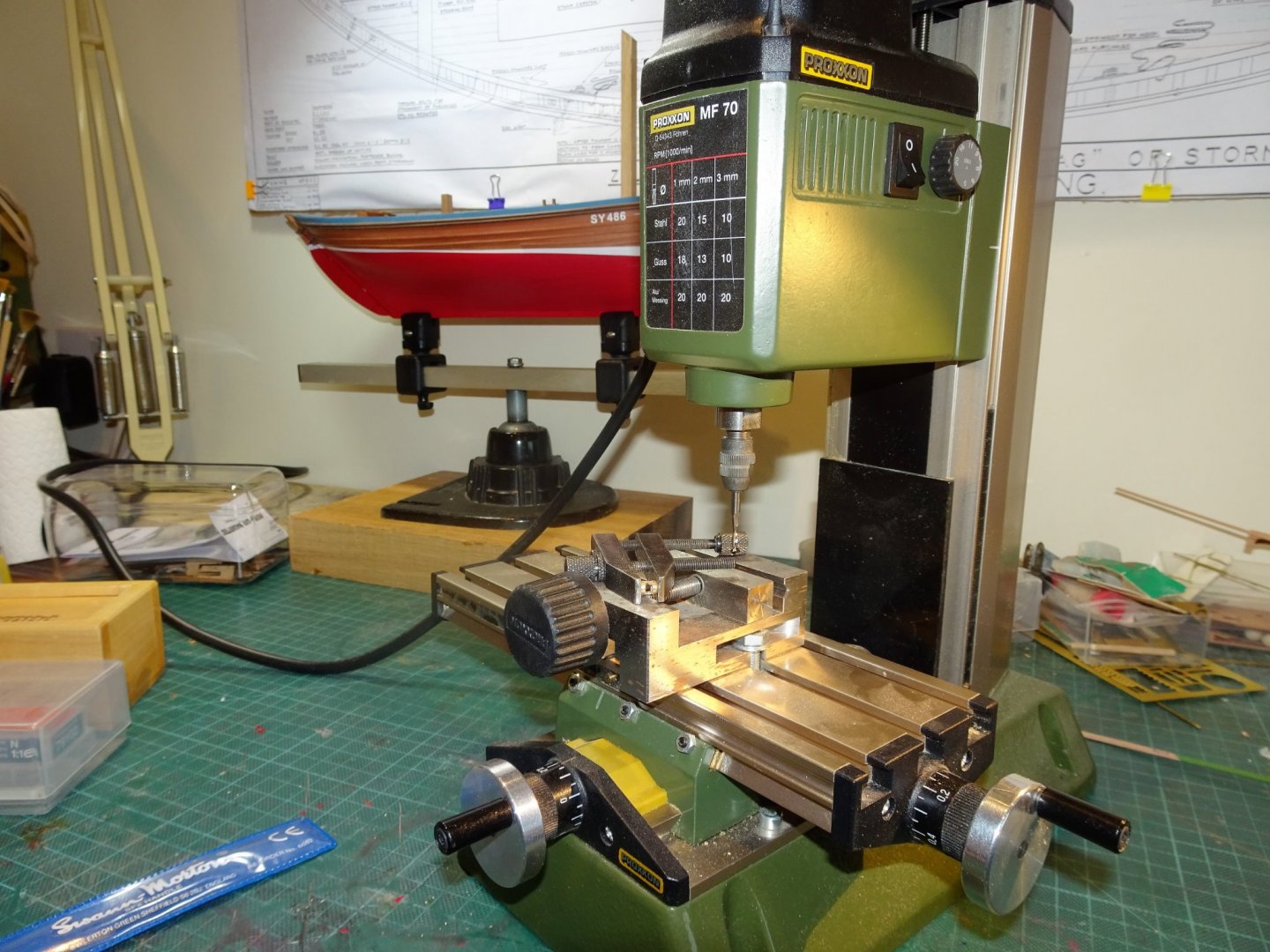
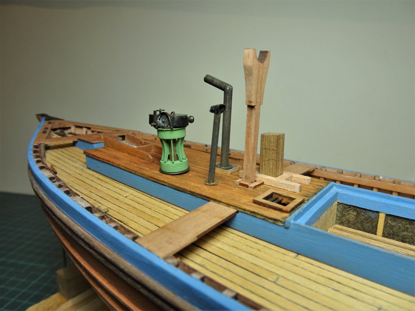
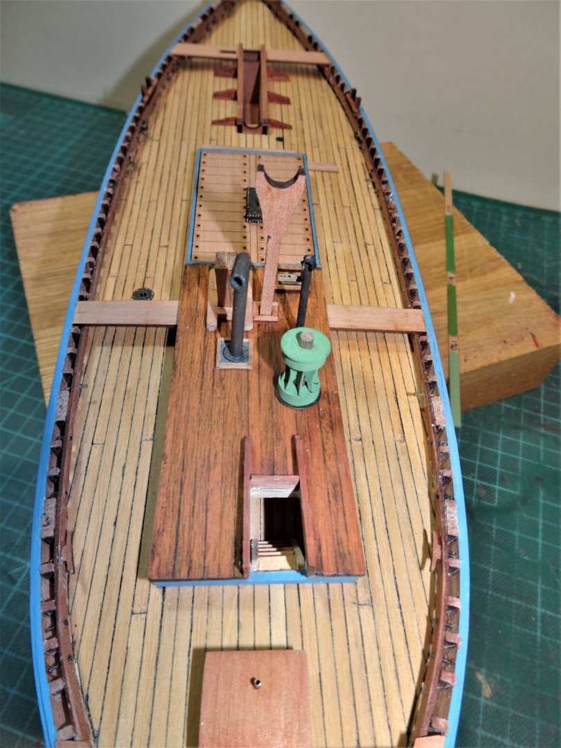
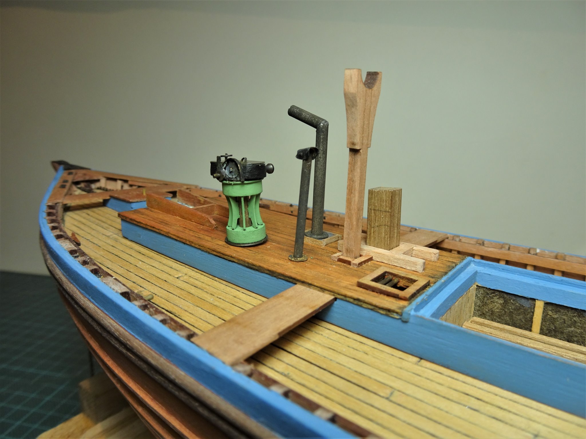
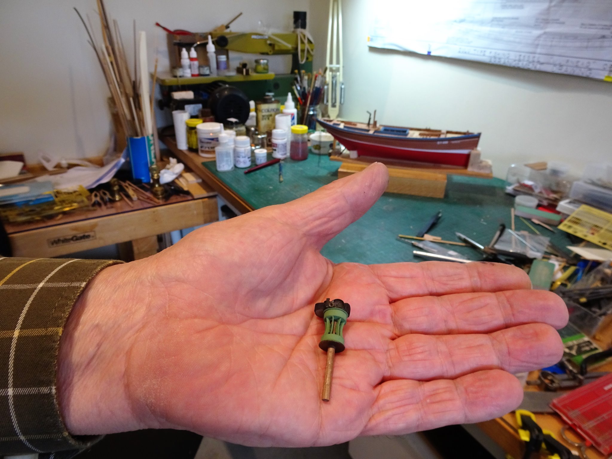
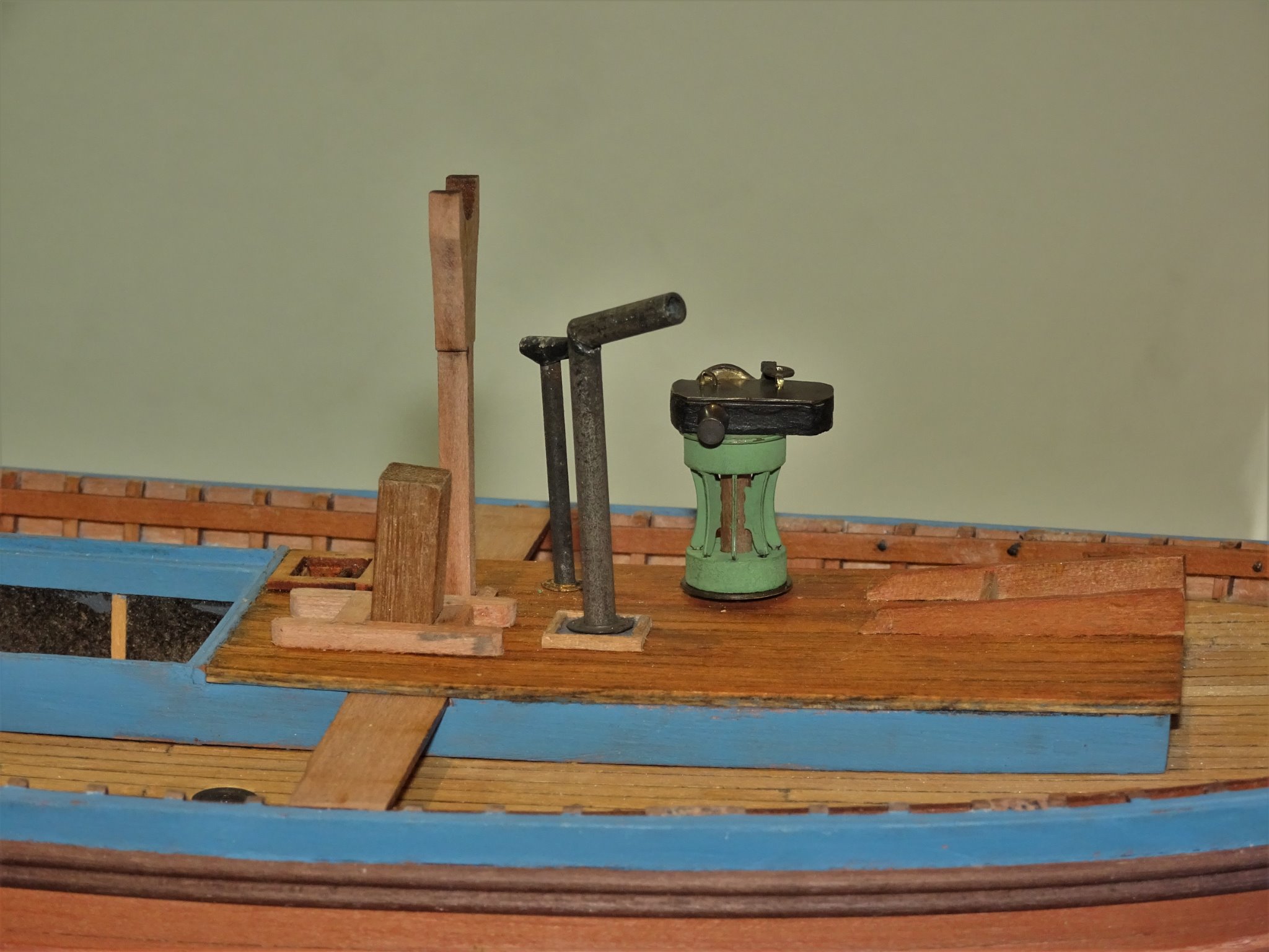
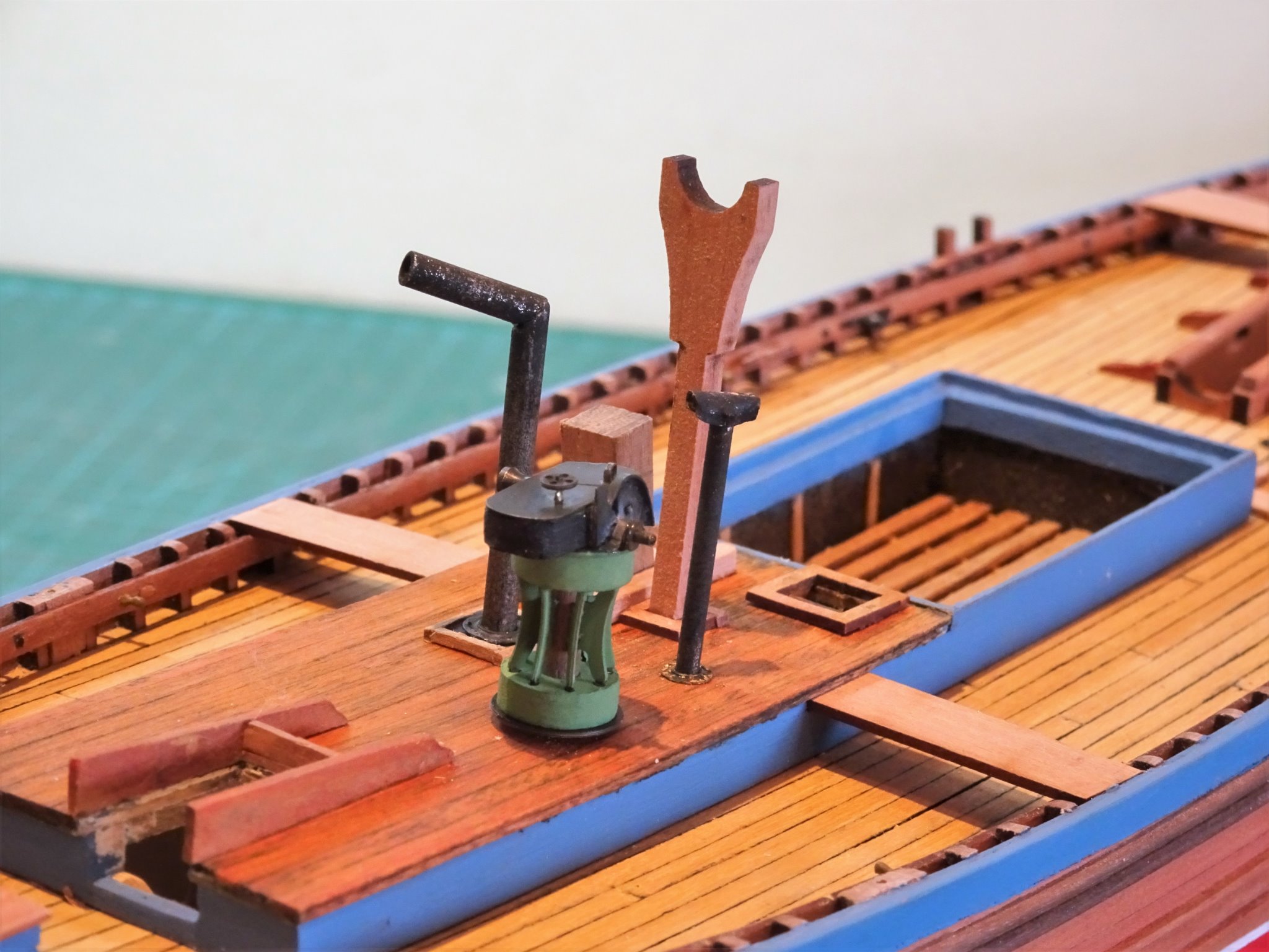
Post 29 Steam Capstan The primary fitting on the Poop is the steam capstan, an eye catching feature which also is supplied with the Fifie kit. Assembly is quite straightforward, built on a central spindle which represents the steam pipe running up the centre of the capstan. For the colour scheme I have used Humbrol enamel (120 Light Green.) I did chemically blacken the brass etch which provides a good primer for the paint. The steam capstan was introduced in 1884 by a company called Elliott and Garrood, a development that the crews of fishing boats must have been eternally grateful for when it came to raising that huge fore lug sail. 8296(3) There is however a difference to the gearbox detail on the Underhill plans, compared to the kit, confirmed by photo’s of Muirneag. Nothing to be lost by having a go to replicate the detail, if all else fails I can revert to the kit part. Working at 1:64 scale presents more of a challenge and the most difficult task is fabricating the gear wheel guard. Here once again 0.20mm brass fret came into use. The pattern was cut out and a piece of narrow strip was silver soldered around the edge. 8299(2) The Blu tack holds the parts in position for soldering. 8304(2) This turned out far better than I thought it might and resulted in a strong bond. 8352(2) 8358(2) The gearbox casing is chemically blackened. 8328 The large gear wheel was made from the brass etched end of a depth charge. 8376 8383(2) 8368 8342 This completes the Poop deck fittings for the present. B.E. 26/10/20
.thumb.JPG.a5f36dfcecebd77b3549cea9c22093cb.JPG)
.thumb.JPG.bca331c411e3fc08398a45fddf630e1e.JPG)
.thumb.JPG.5cef92d42f0ab066c5cc56fffc80b32b.JPG)

.thumb.JPG.fcae0b61b176d1823812c8588bfc02de.JPG)
.thumb.JPG.666e15498ad66b8b329c7dbb751169b0.JPG)


.thumb.JPG.94b8378caee15c728b5169ed86b9af85.JPG)
- 261 replies
-
- 18
-
-
- muirneag
- vanguard models
- (and 2 more)
-
I don’t own any other micro chisels Glenn, but these are fairly cheap to buy, the blades do hold their edge, can be re- sharpened, and are easy to replace. At the scales I work at they are a useful addition. B.E.
- 261 replies
-
- 1
-
-
- muirneag
- vanguard models
- (and 2 more)
-
Fifie steam capstan - for hauling nets, sails or both?
Blue Ensign replied to Rik Thistle's topic in Nautical/Naval History
I think you are correct Richard. The steam capstan was introduced in 1884 by a company called Elliott and Garrood. It must have been a boon to the crews of fishing boats when raising those huge lug sails.. I have also read that it was used to assist in hauling the nets, no surprise given that the nets could stretch for half a mile; must have been quite a drag when they were full of fish. B.E. -
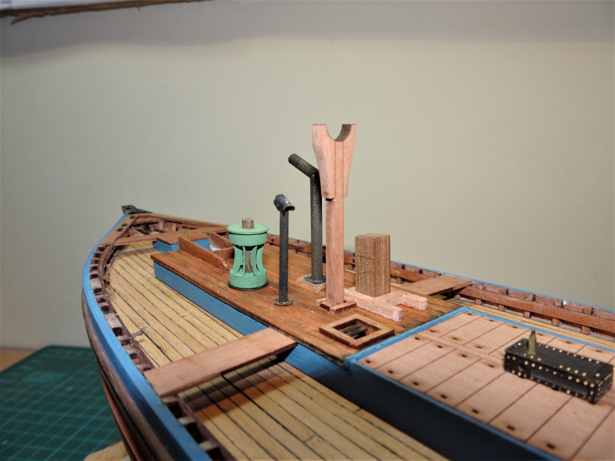
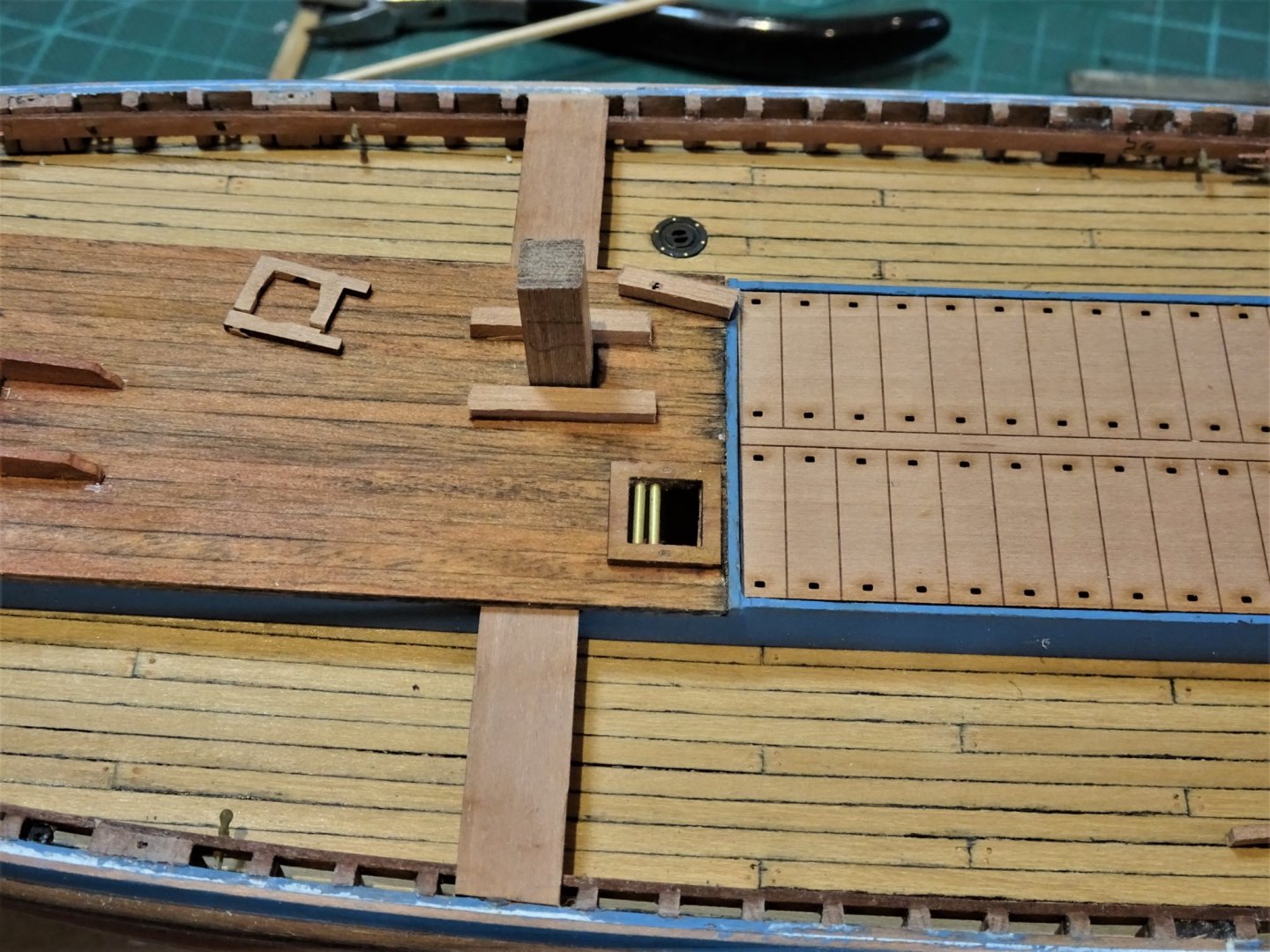
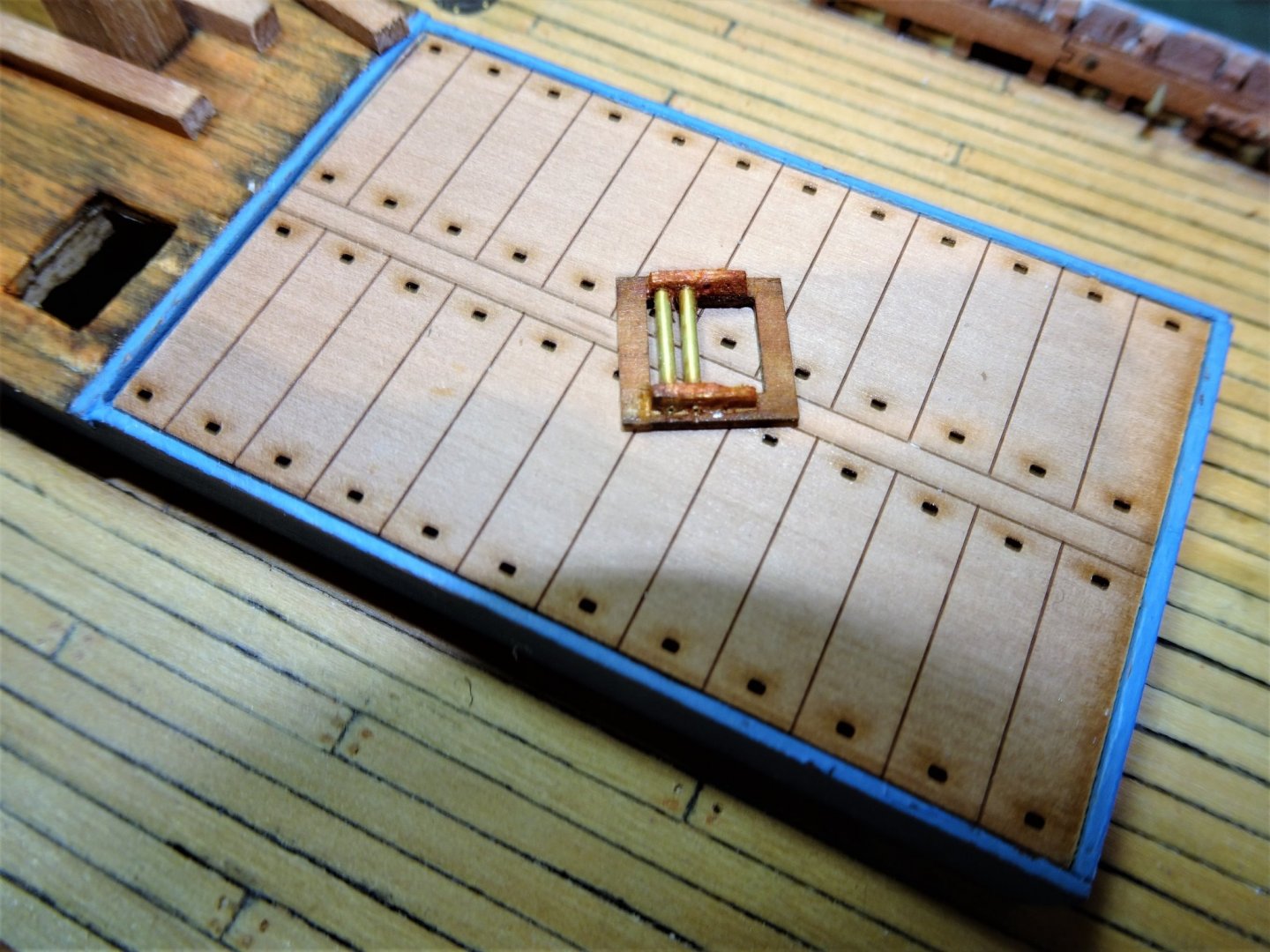
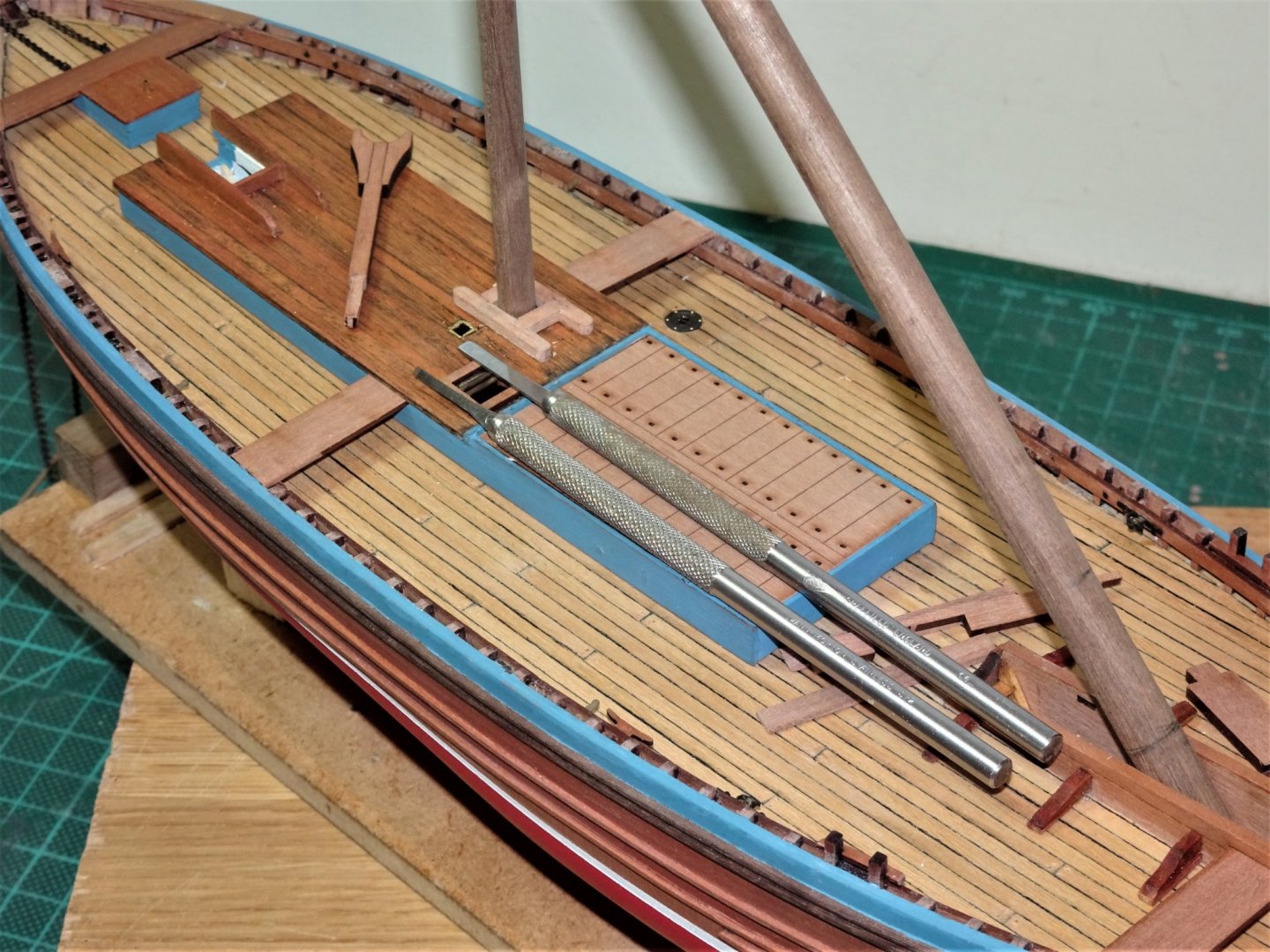
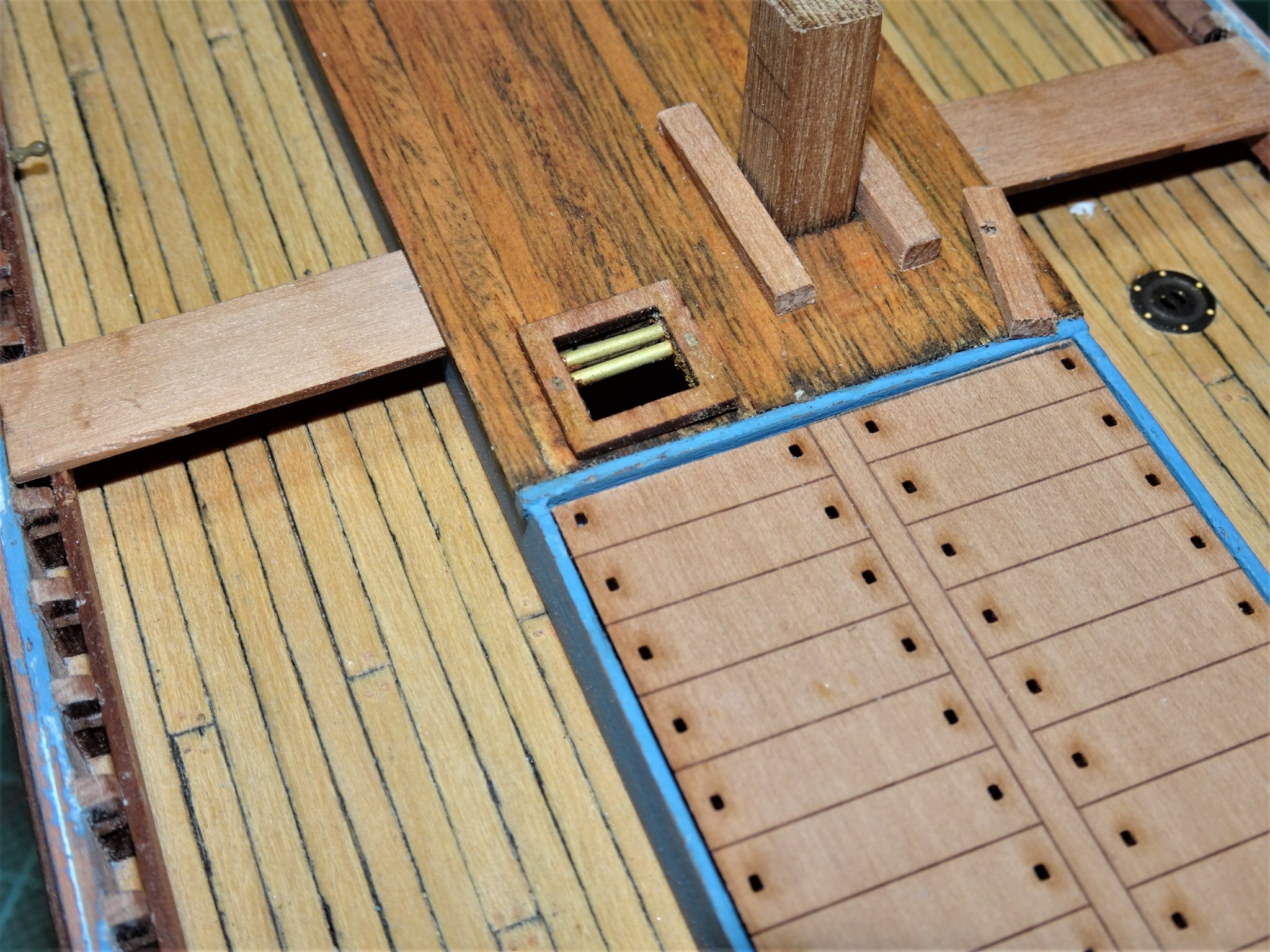
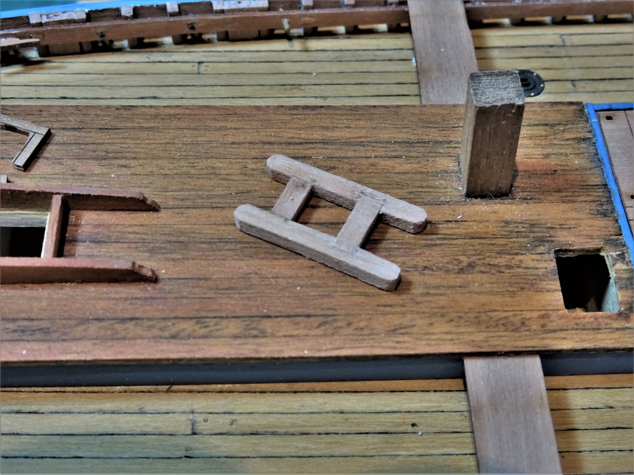
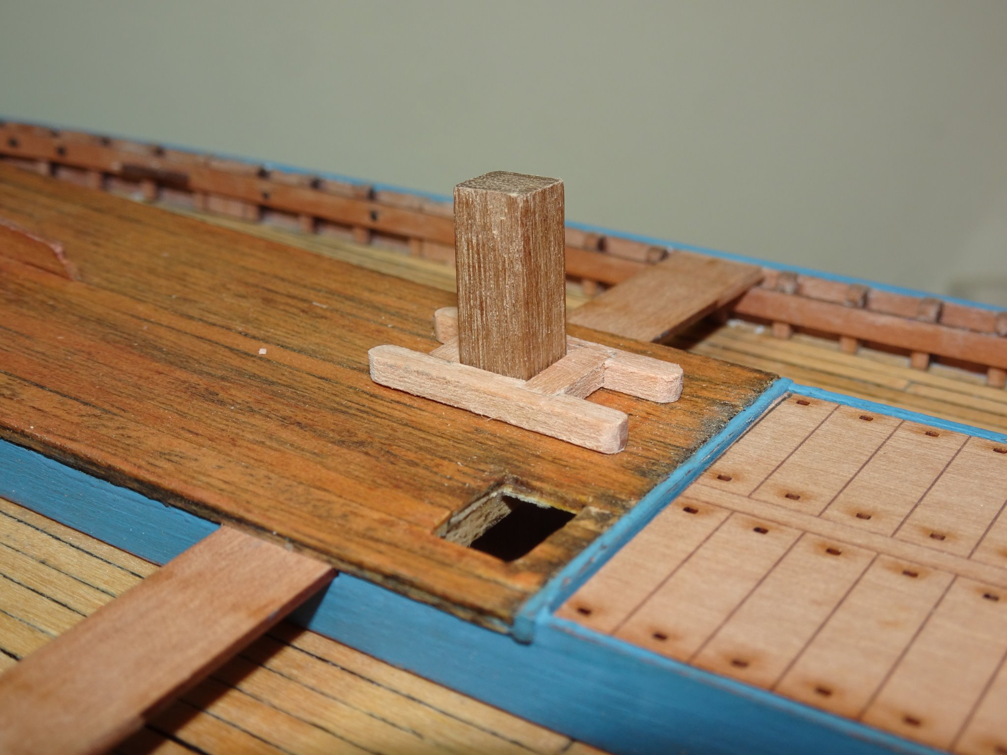
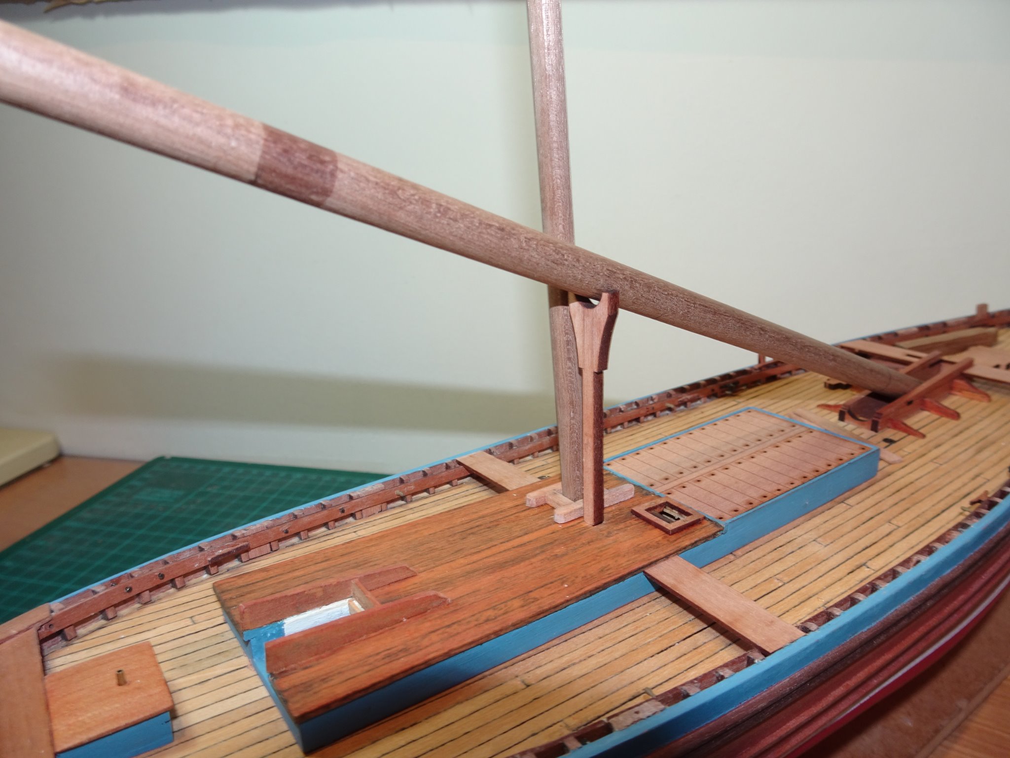
Post 24 Fitting out the Poop I am now into my favourite part of a build, fiddling with the fittings. The Poop deck has a wealth of detail, the positions of which I now need to fix. The kit contains all the right features but not necessarily in the right layout for Muirneag.(apologies to Morecambe and Wise) The Mizen mast is square at the partners which were scratched to suit, and the other fittings positions were tweaked to reflect the layout on the Underhill plans. The kit warp hatch rollers seem to be rather stylised and are represented by etched housings sitting above the level of the coamings covering most of the hatch space. I was able to utilise the provided coaming which is about right for scale, but I had to enlarge the hatchway slightly to accommodate carlings below the coamings to allow for the rollers to be set lower within the hatchway. 8181 False carlings were glued beneath the hatch coamings which were drilled to take short lengths of 0.5mm brass wire passed thro’ 1mm brass tubing from side to side to secure the rollers. 8177 Completed Warp Hatch in place. 8174 Also in this photo the makings for slightly beefed up mast partners, the now defunct kit part can be seen on the Poop deck aft of the mast. 8215 The mast partners were remade using spare 3mm Pearwood from the kit fret. 8217 All the spare wood around the laser cut parts comes in handy for scratching alternative parts. With the Warp hatch and partners glued into place, the position of the crutch can be determined. 8225 The crutch which supported the lowered Fore mast is nicely pre-made in Pearwood and on Muirneag sits immediately to the starboard side of the Mizen, rather than just aft of the partners as indicated on the kit. The Underhill plan indicates a height of 8’ 2” = to 38.9mm at scale. The kit part is pretty much spot on for this. 8226 I used a section of square brass tubing to provide a socket to take the Crutch. 8229 These Swann- Morton micro chisels prove invaluable in cutting small holes. The Boiler flue is provided in the form of Aluminium tubing and a circular etched brass base plate. 8224(2) I have modified this to accord with the Underhill plans where the flue base is a concrete square set in a wooden frame. The smaller stove flue was modified to fit a cowl over the top. Blackening Aluminium doesn’t seem to work as well as on brass, and I do have a jar of Aluminium specific blackener. 8287 May need to re-visit the finish on the flues, but a part of me quite likes the weather beaten look. 8283 The partly completed capstan in place, I have been looking at photo’s of the capstan on Muirneag, and I feel the urge to have a tweak with the gearbox…… B.E. 25/10/20


.thumb.JPG.9f40cc4f60bc39e52c62fd488211d245.JPG)

- 261 replies
-
- 14
-
-
- muirneag
- vanguard models
- (and 2 more)


.JPG.50b03041c24ee6cb2309051182cefbc4.JPG)
.JPG.e9ef05bf00c49f34f6e4a1401eca1604.JPG)
.JPG.dd0226a11a7ac34478ccbd7f1eb0262b.JPG)
.JPG.0e57a9192a4a46d5ba9856624e5a8a6c.JPG)
.JPG.7c7805e8a8ea38ff5c4cf8d4cc09b96d.JPG)
.JPG.64589d14007615997fa2aafd7ea77e20.JPG)
.JPG.e347aa574f896c7d10cbad614443cfb9.JPG)
.JPG.6a4472221eda0fa04b8b0bd17ec0d3c1.JPG)
.JPG.af434c069ec87a27cf37560148cc2756.JPG)
.JPG.fe57e7d32167bc3aa4cdc2a9e66d3abb.JPG)
.JPG.c83d5611effdd37bf8f5064029d3dd8e.JPG)
.JPG.4f9f0739971479e646d3e45c81b6570a.JPG)
.JPG.faa5d7d7ac791ebdb83df1f77b8128d4.JPG)

.JPG.84912b583e600bd3e1f1adf1716f3b99.JPG)

.JPG.9a5f4eecc12e2a8f857ef3fa81b5accc.JPG)
.JPG.3ef6098886864f28384a3d010e24c68f.JPG)

.JPG.6fcbf52ea830f262546df83da0fce975.JPG)

.JPG.595b568a30194cb590446fe5e3e8e0c8.JPG)

.JPG.b8c61688aaddf16d5e9b0b0bfb75bce2.JPG)


.JPG.8bf691785c67f0823b12ddd55e415643.JPG)
.JPG.41aad1c4c18a8206014ed98ed05a91c8.JPG)
.JPG.4a2011bb1bdca7204049172cdb4d5615.JPG)
.JPG.f3bcb36a36996ef7a78efe059001afea.JPG)
.JPG.497ca4c688b438e9fa69046d2c8ac61d.JPG)
.JPG.606c852f6eb9edd35f05b6ae728eb638.JPG)
.JPG.7ec7b33b41bd9b8720f05a7bb7f6de78.JPG)
.JPG.60dcfe4a64e86f36f2c356e2cf37b67c.JPG)
.JPG.8246566904a90c7c868094ef30b88820.JPG)
.JPG.276bdeab31336e47acc9664428b6950c.JPG)
.JPG.fddc72459357813e6142a91560c4df29.JPG)
.JPG.4596c0f650c8fd7162e31a6d3efb50e6.JPG)
.JPG.c6b20c1d5dde06835ad2418f38739fac.JPG)
.JPG.60bb8ae3f9348e4a7fd5241688c923b1.JPG)


.JPG.73efff1555309e02a8a7a76bf7e25889.JPG)