DaveRow
-
Posts
691 -
Joined
-
Last visited
Content Type
Profiles
Forums
Gallery
Events
Everything posted by DaveRow
-
 Hi Greg, Master Boat Builder or a budding Artist in the making ? Seems it may be both by the excellent details you have applied. Dave R
 -
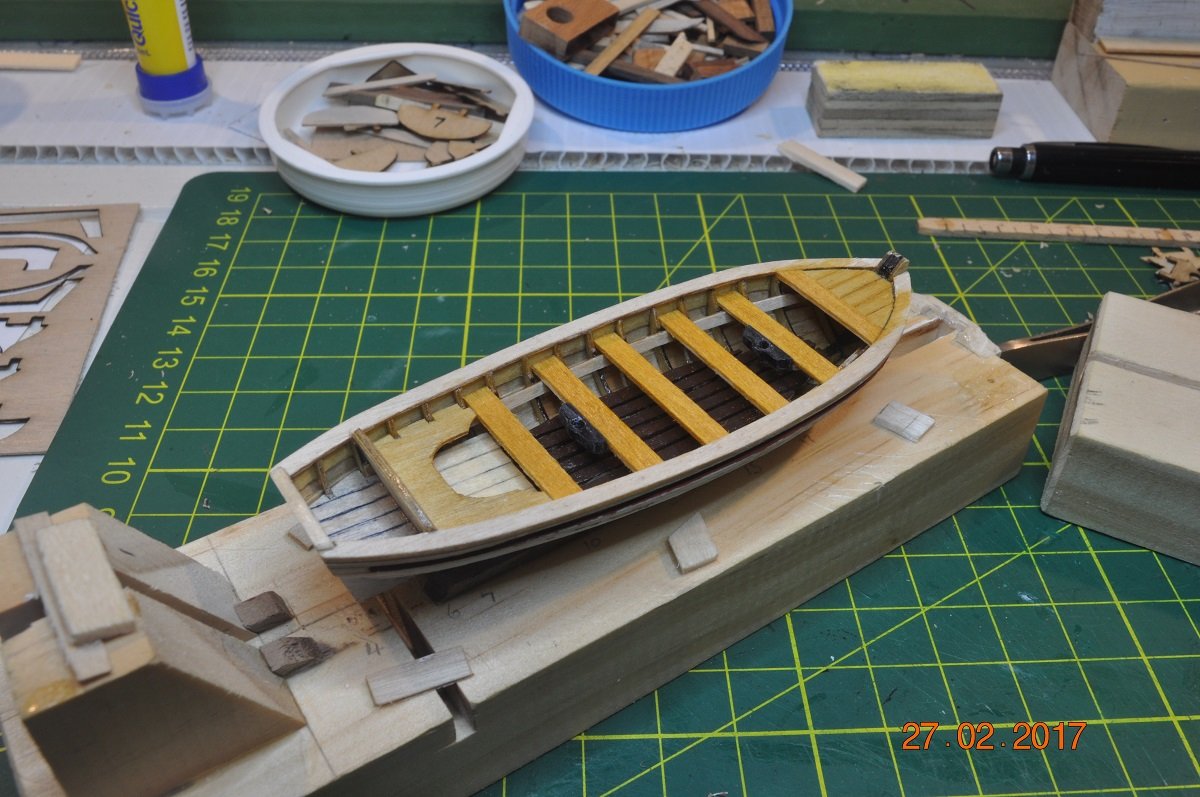
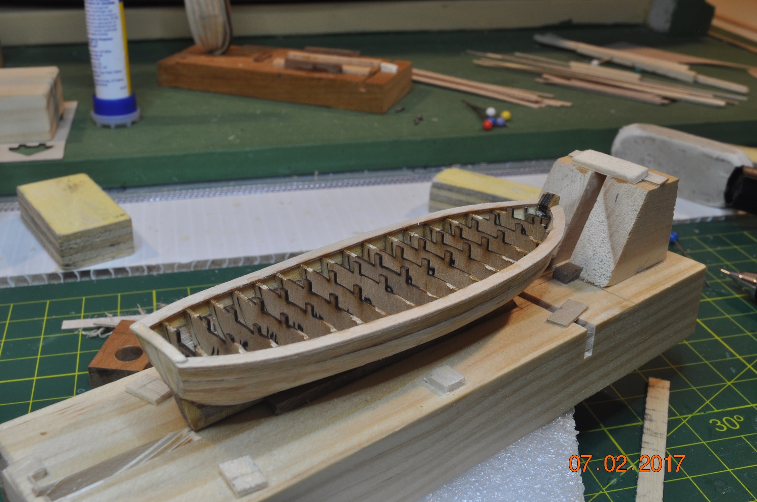
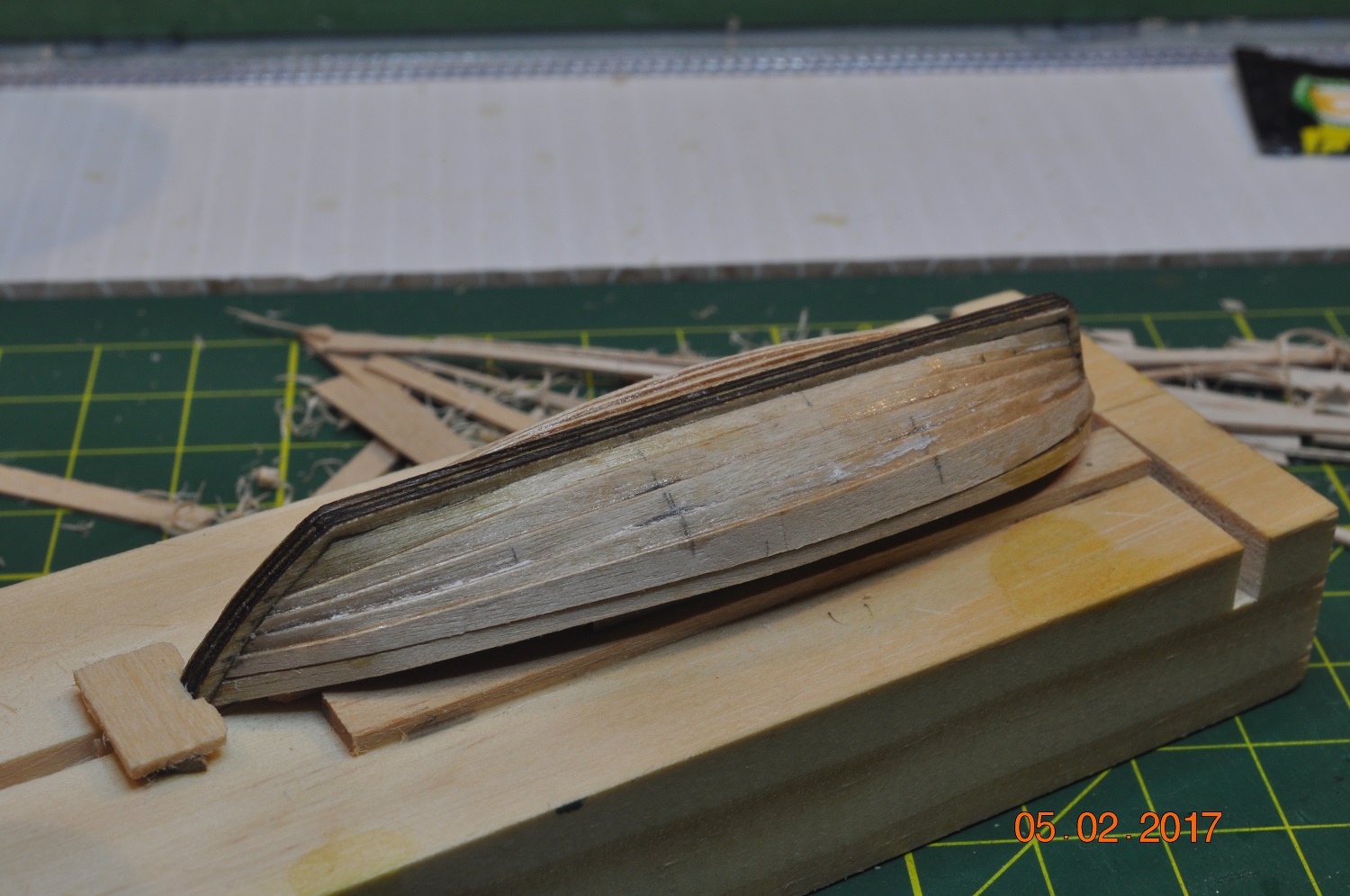
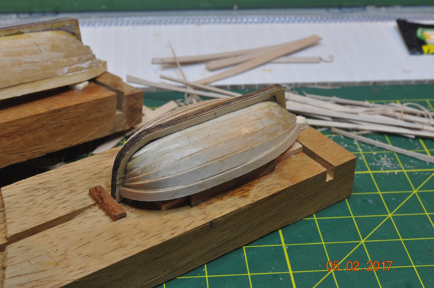
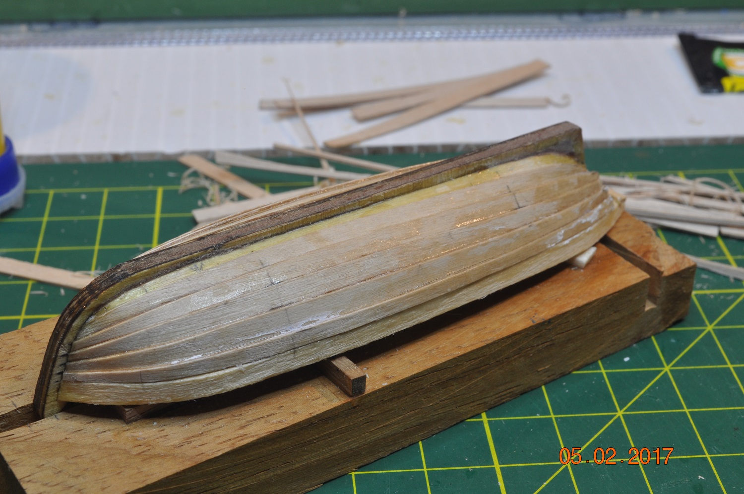
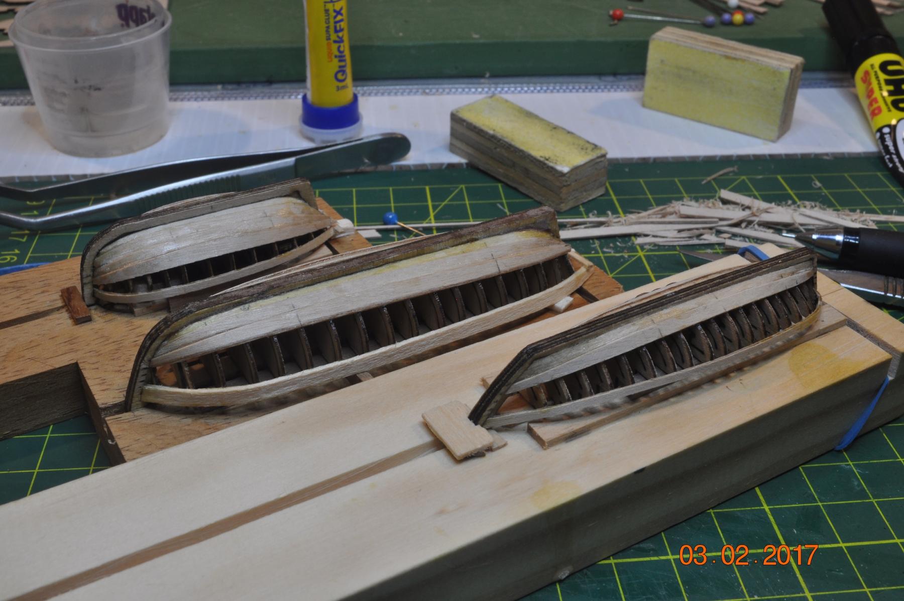
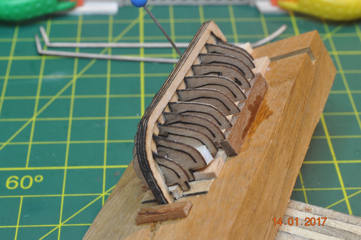
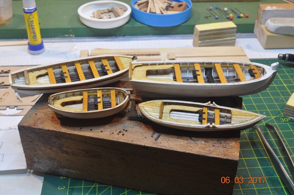
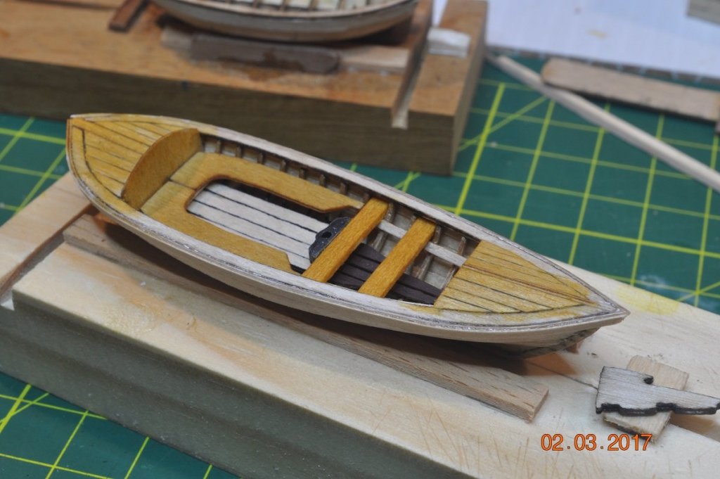
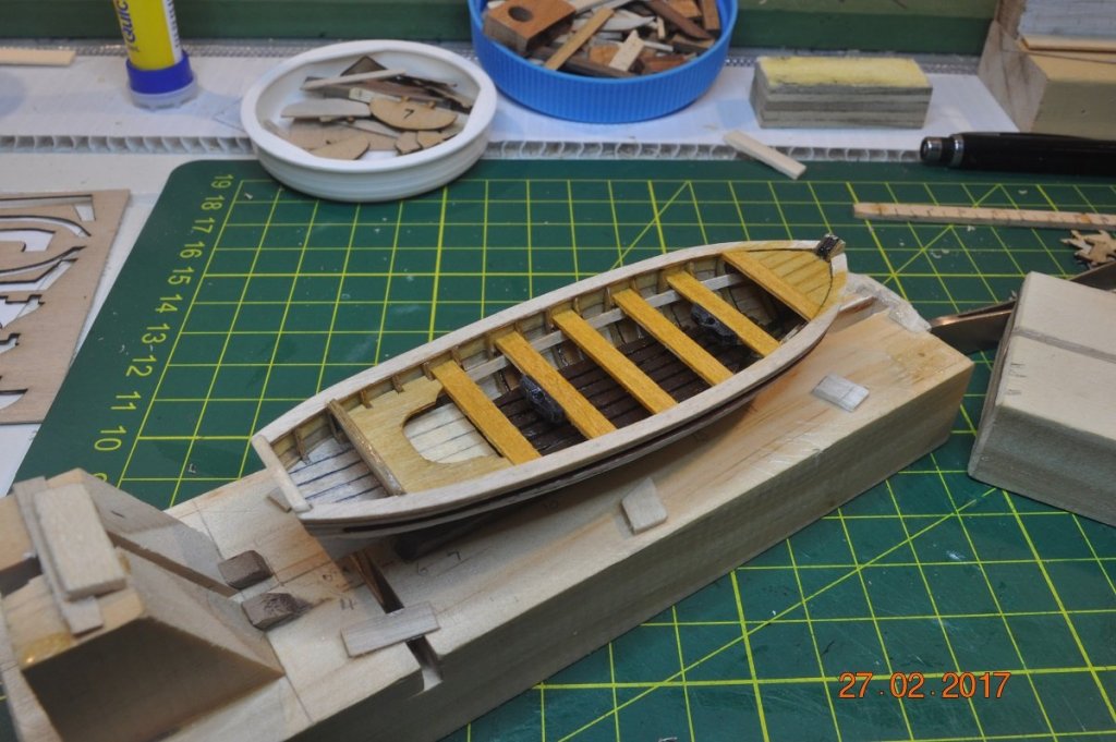
Ships Boats Update Skiff Started on the fit-out of the Skiff. Added the gunnels at this stage and removed the removable sections of the frames. Inner fit-out nearly completed. Yawl Started on the fit-out of the Yawl. Middle of the frames in front. 4 Ships Boats Has taken a while to get his far with the 4 ship boats. Each is about the same stage, next to finish hull paint job, rudders and some oars maybe masts. Dave R

- 869 replies
-
- 10
-

-
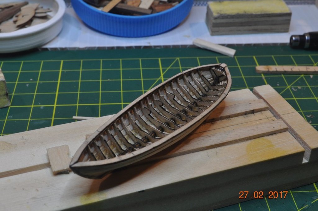
Ships Boats Update Pinnace It has been slow going working on this little boat. A couple of pictures of where the shipyard is at today. Much more to go, however will finish all 4 small boats rudders, paintwork, masts etc. together. At this stage I am happy to move onto the Skiff, work on the fit-out, bring it up to the same stage as the Pinnace and Longboat. Dave R

-
Nice Yards Steve. A lot of work their. Wish I was making mine. My 4 small boats are taking much longer than I though possible. Dave R
-
Good desk, refurb. I used an old T&G toilet door as my desk. Dave R
-
I love reading this stuff, and imagining to be on board a square rigger back in those days. or not. Dave R
-
Another attraction at the "Hobart Wooden Boat Festival 2017" were a number of speakers at the Wooden Boat Symposium. Of interest to those building the HMB Endeavour would be the presentation called "On the trail of Cook's Endeavour" Dr Nigel Erskine, Head of Research for the Australian National Maritime Museum(ANMM) presented a very exciting talk of the efforts to confirm the resting place of the Endeavour. The talk commenced with some background of the Endeavour leaving England. Cook's 1768 journey for the transit of Venus, and onward to the Australian coast. Delivering provisions to the Falkland Islands in 1772. The paying off of in 1775 to be renamed the Lord Sandwich, and unceremoniously, and purposefully, sunk in 1778 in the shallow waters of a Rhode Island harbor to block advancing French ships. Of recent times he described how the ANMM and the local Rhode Island Marine Archeology Project (RIMAP) at Newport have partnered to locate the remains of the Endeavour(Lord Sandwich). He told us of the efforts to date and the challenges they have met and ahead. He is hopeful they will be able to confirm which of the 13 hulks on the seabed is the Endeavour. Nigel showed us maps showing the locations of the sunken ships and underwater video over the area. Dave R
-
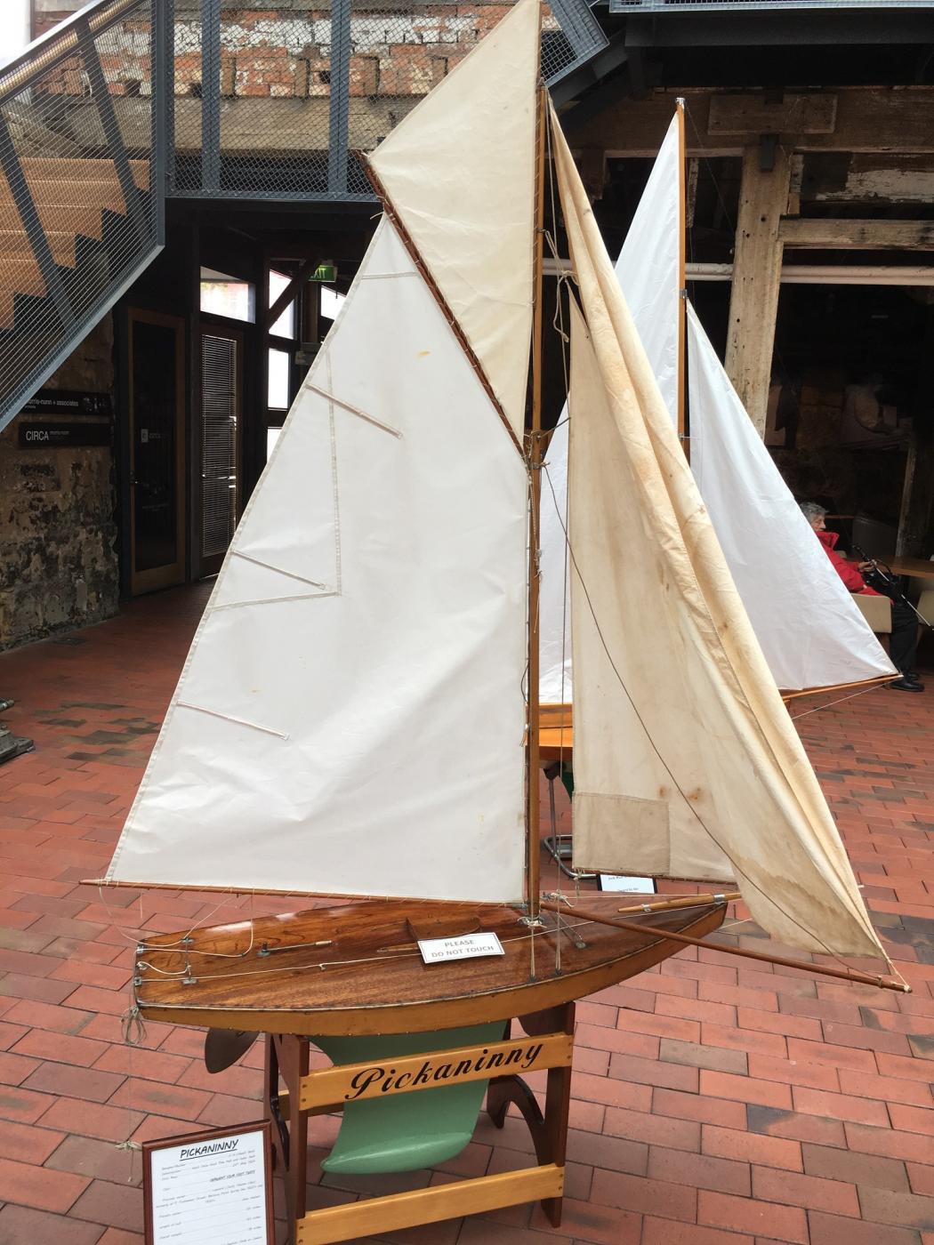
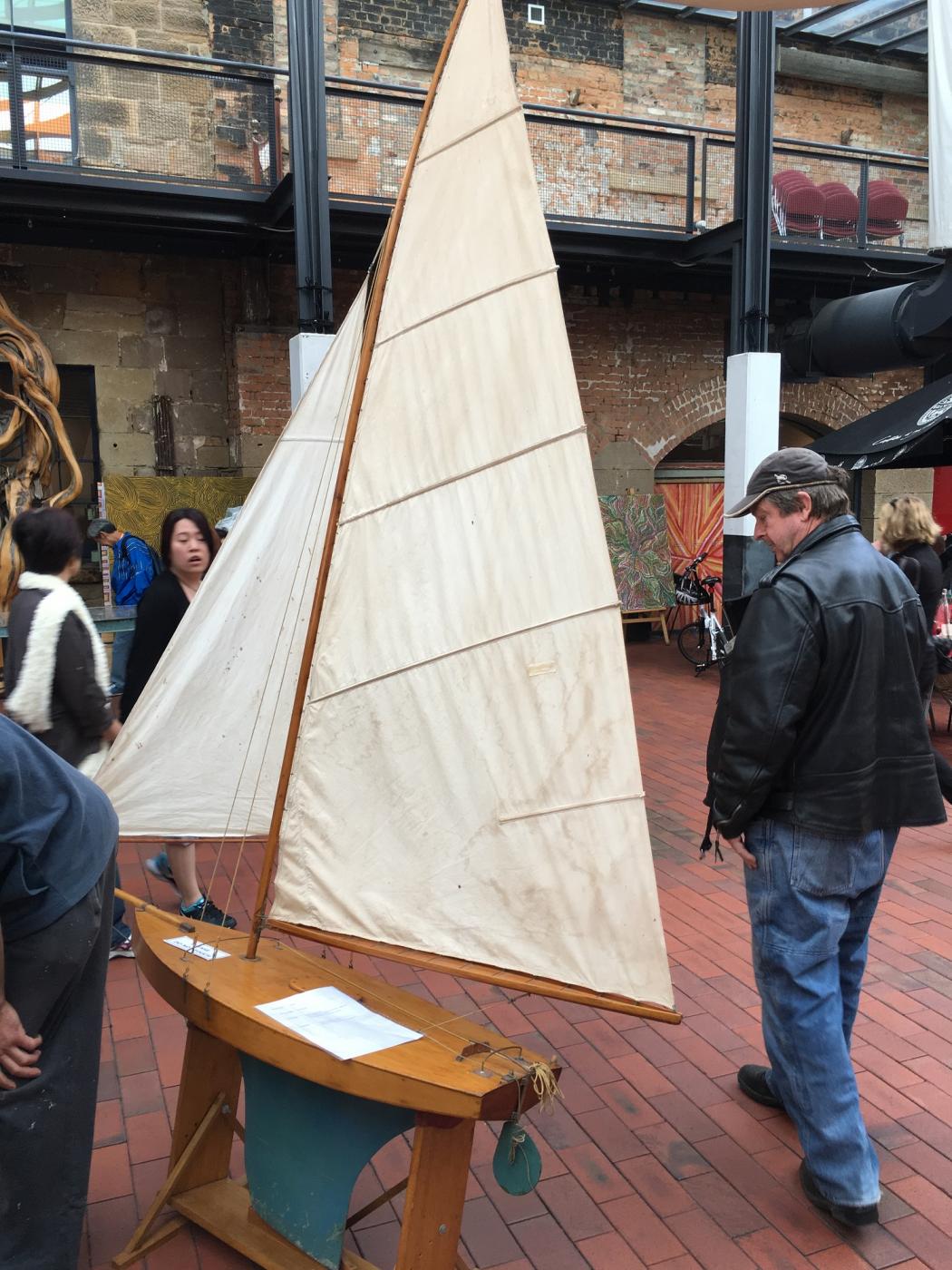
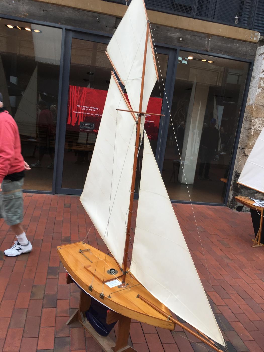
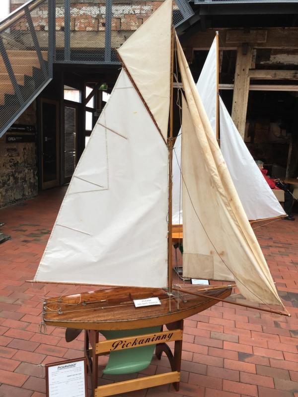
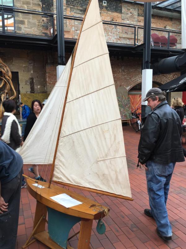
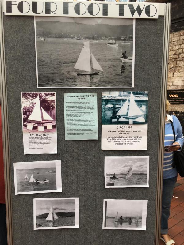
Below are some of the "Four Foot Two" which were on display at the "Hobart Wooden Boat Festival 2017" Their were a good 9 to 10 of these models which used to sail back at the turn of the 1900's Bit of a story about them on the first picture(Board) Dave R

-
Well done Rexy, A milestone in itself plying the first layer on. Am I allowed to say, now the fun starts with the second. Have you thought of how the hull/planking will be finished ? The lay of the planks ? Clear or part painted ? This Picture is of the bow of the Replica Endeavour, showing the planking coming forward. Hope you don't mind me chiming in. I finished mine clear with slight brownish stain below the waterline. Dave R

-
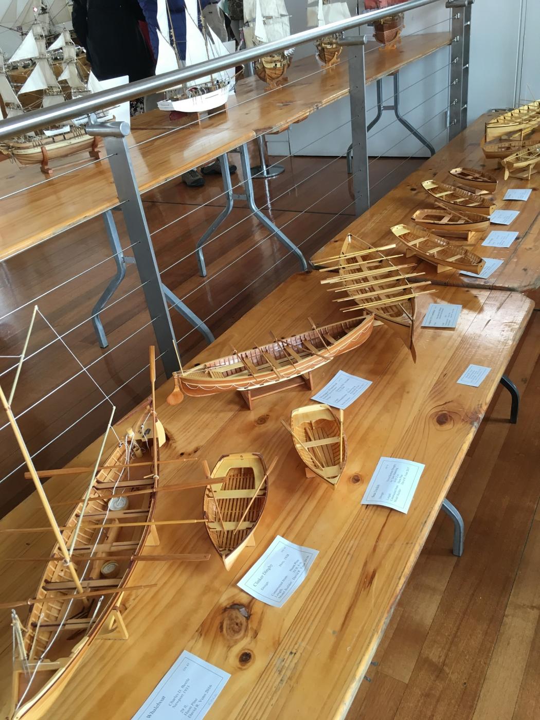
I have pictures of most of the models at the show pavilion. Very nice "Surprise" and "Cutty Sark by Don Ash" Their were several old "Four Foot Two" sailing model boats from way back in the 1895 - 1930. Not sure if owner's would like them posted without permission though. Dave R
-
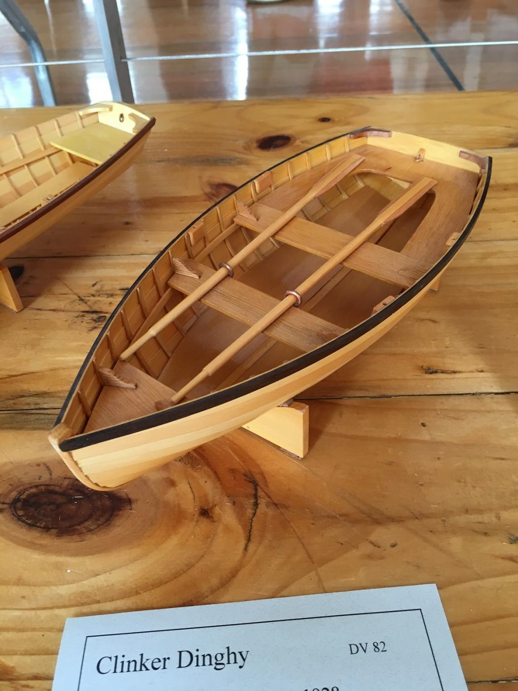
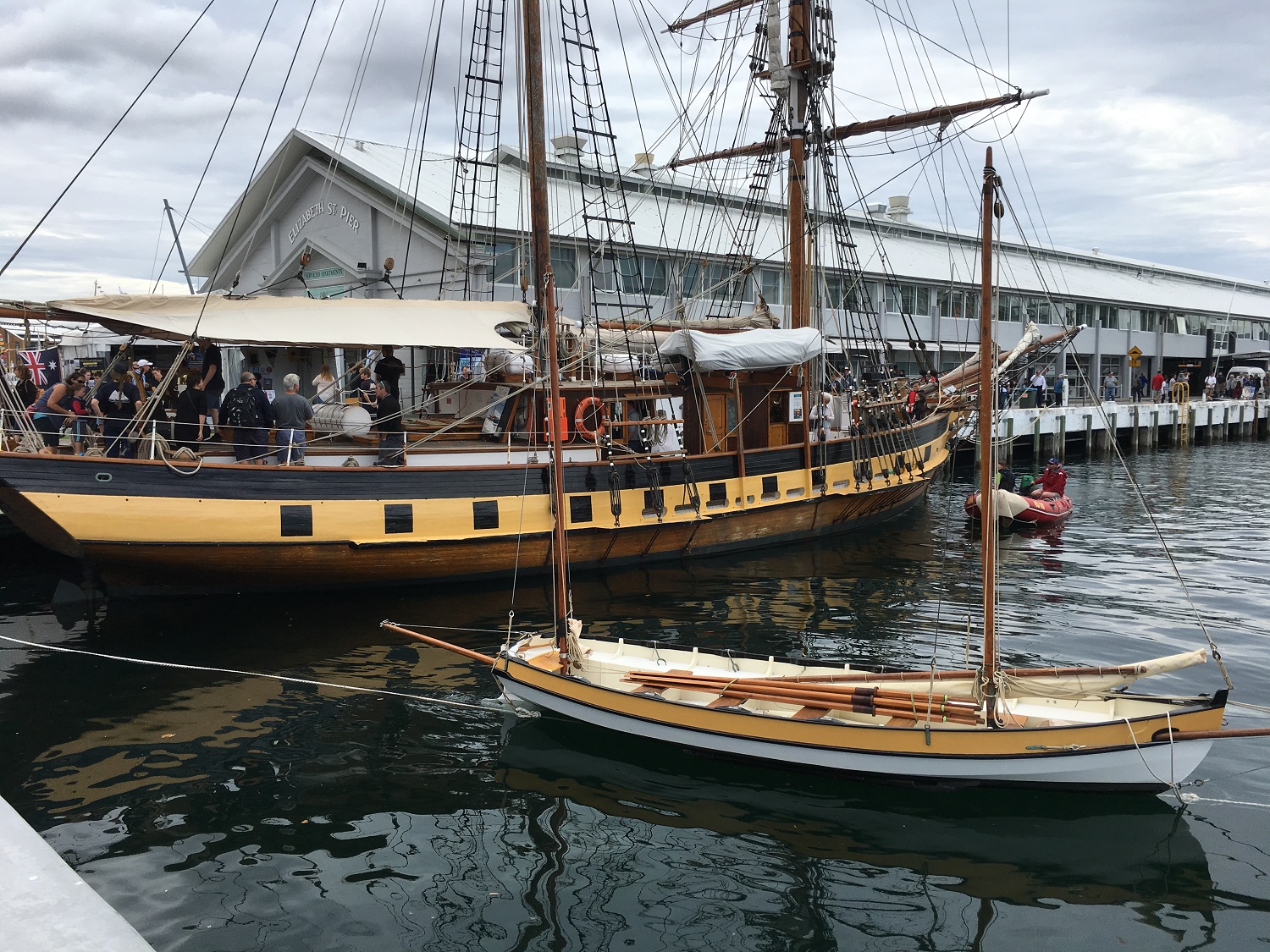
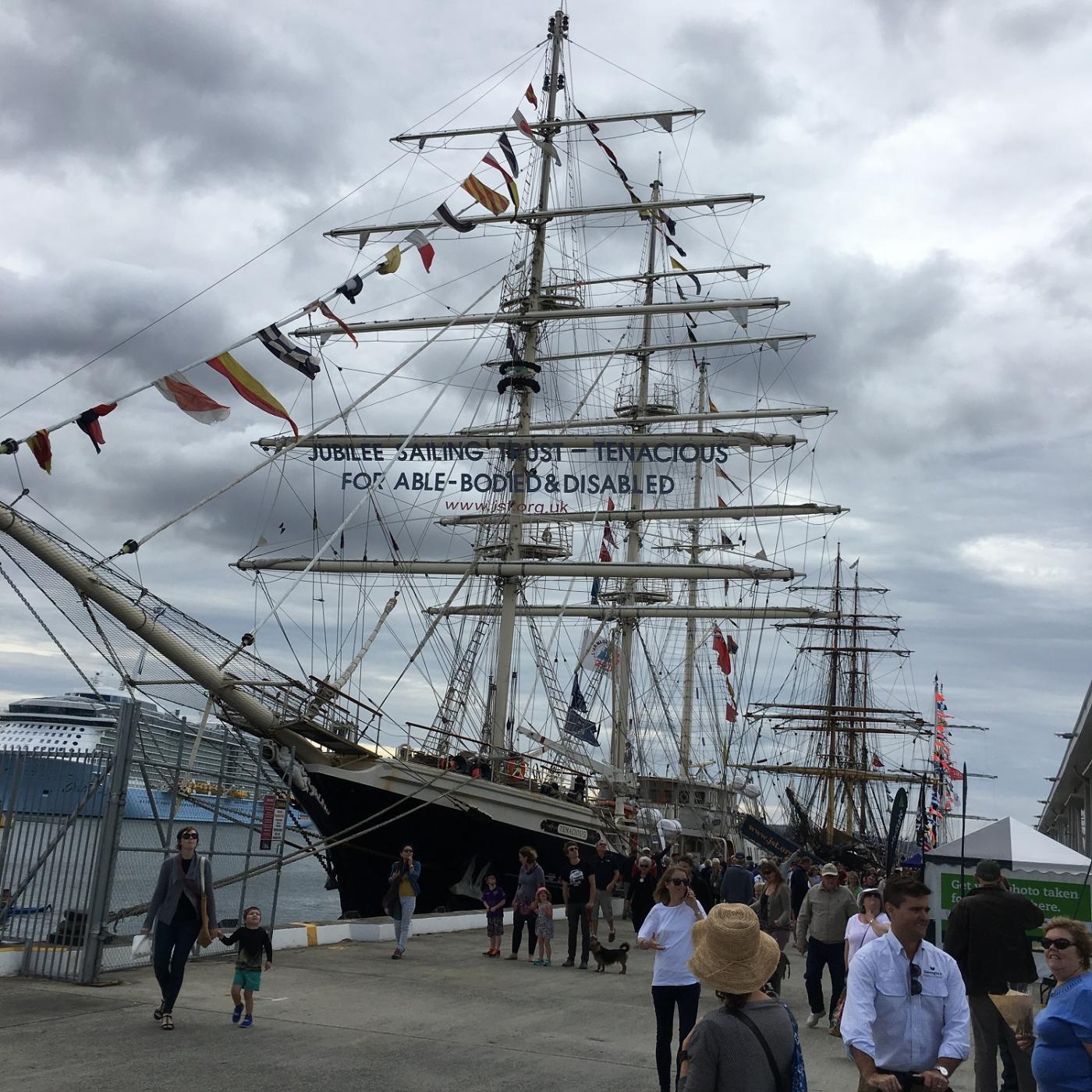
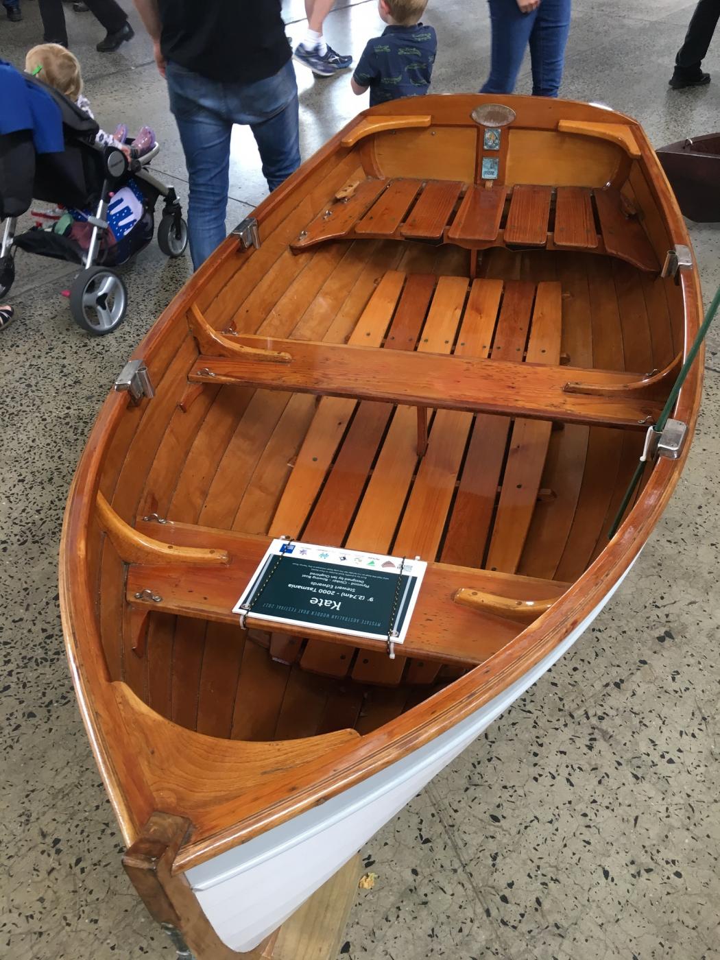
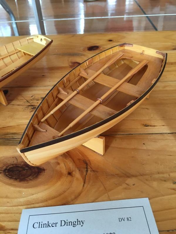
Just returned back home to Brisbane from the Bi-Annual "Hobart Wooden Boat Festival 2017" Fantastic 4 days viewing plenty of old, restored, models and new wooden boats. Some Pictures below. Model of a Clinker There was something for every wooden boat enthusiast. Dave R


-
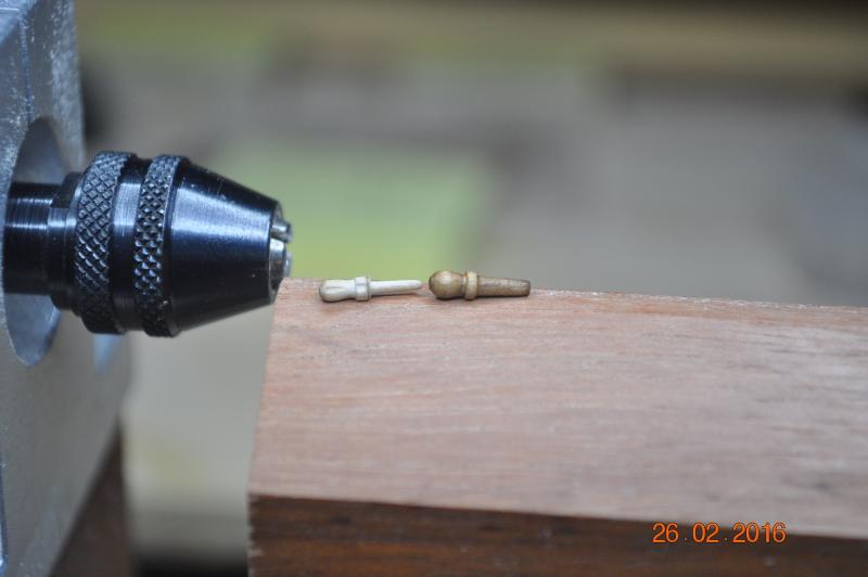
Hi Michael, I tackled ? this back in Feb 2016. My soluition was that I purchased the smallest market "belaying pins" I could find, and placed each in my Dremel and turned each down smaller. See Pic. below A bit of discussion back in my log re above. Feb 16 timeframe. I stained and clear coated at end. Dave R
-
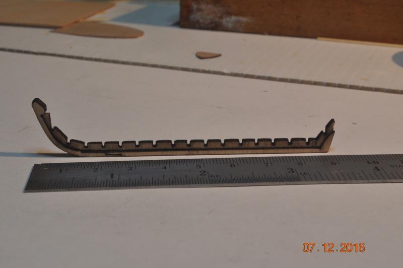
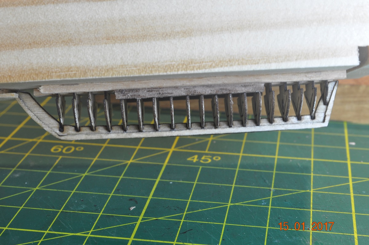
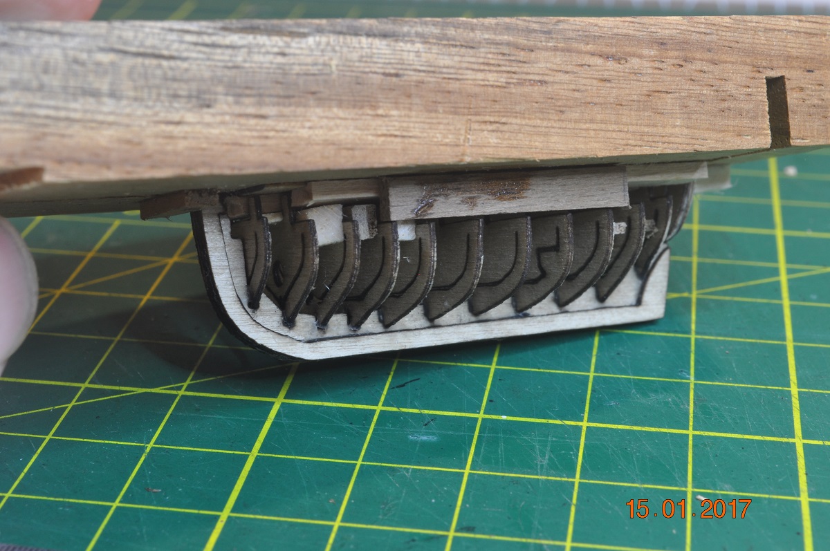
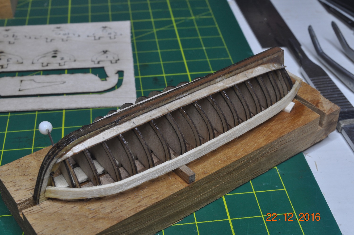
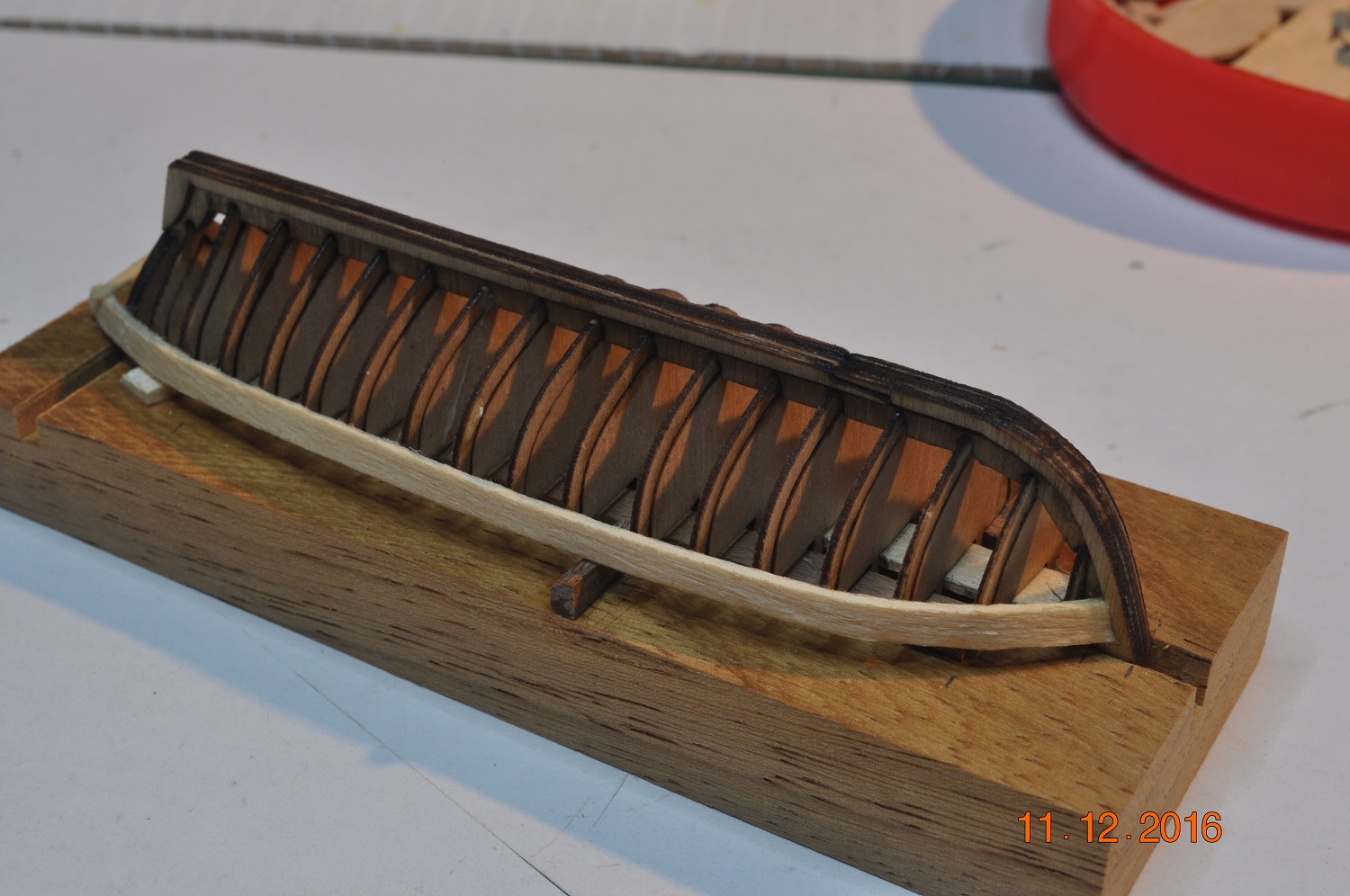
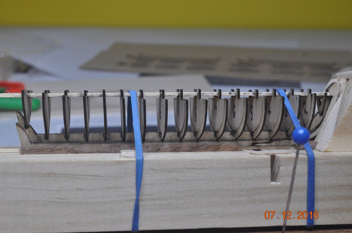
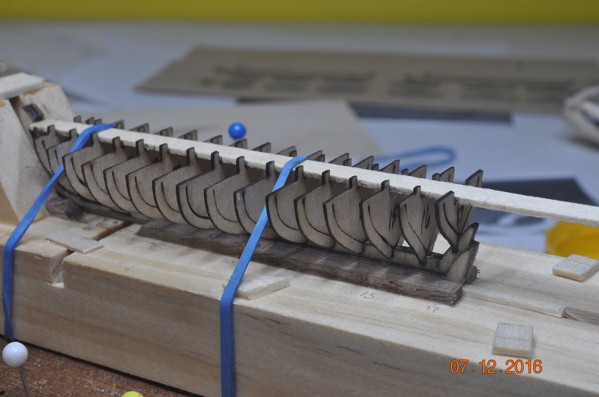
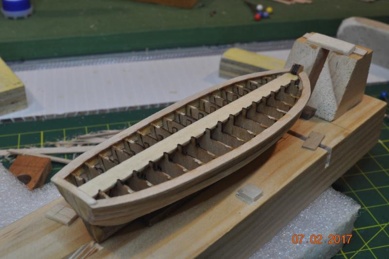
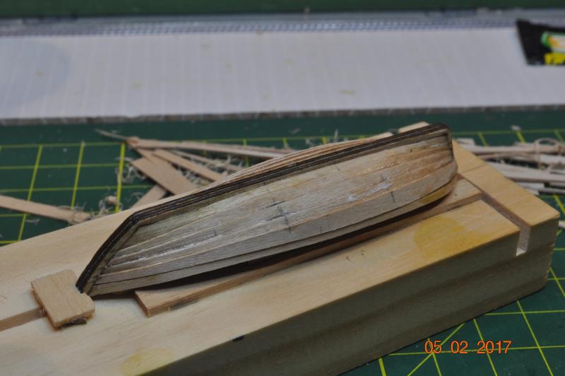
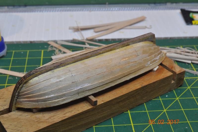
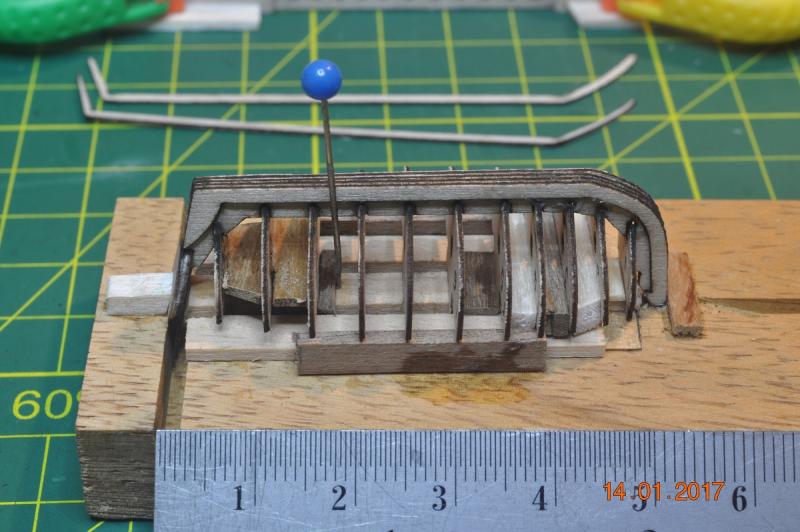
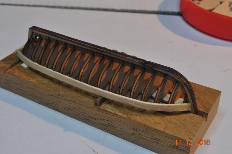
Ships Boats by the Shipyard Been very hot here in Brisbane Australia. Not conducive to working on small boats in the heat, even with AC on. Here are the three boats I am working on together. Planking underway. Yawl Planked: Skiff Planked: Pinnace Planked: Pinnace turned up, revealing frames alligned with central runner plank. Added the gunnel to P and S, should be stiff enough now. Removed the central runner plank. Plenty to go. Dave R


-
Save the Treenails for the second layer. Dave R
-
Hi Steve, It has been a nice break away. New year, new targets. Nice start to the yards. Keep going. Dave R
-
HMB Endeavour by mikec - Eaglemoss
DaveRow replied to mikec's topic in - Kit build logs for subjects built from 1751 - 1800
Hi Mike, Good break is needed at times. I'll be starting on yards after I get me 4 boats done, which is very slow at the moment. Dave R -
Rexy, 1 plank each side per day is about right, same as what I could manage as well. All takes time measuring, tapering/trimming, getting the bevels correct, steaming and bending, gluing etc. Oh what memories. keep up the good work. Dave R
-
Mike, Your question "Two questions about the mainmast forestay. It looks like it splits and goes p & s around the foremast- a loop, joins back to a single line. Is this correct? And, I can't identify where it terminates at the bow." I have only looked at this a while ago, and may be wrong. Ref > AoTS Page 95. Only the Foremast have "fore" stays. Do you mean the Main Preventer stay and Main stay ? I believe so. Both are separate stays. Each at top looped around mast joined with a mouse. AoTS Page 99. The bottom connections - AoTS Page 99. Main Preventer stay loops "collar" '15' around the foremast. Main Stay passes the foremast(looks like on starboard) and fixes to ? AoTS shows a eyelet on the deck and Replica has it under the Bowsprit. These two pictures are from Replica: Hope that helps. Dave R

-
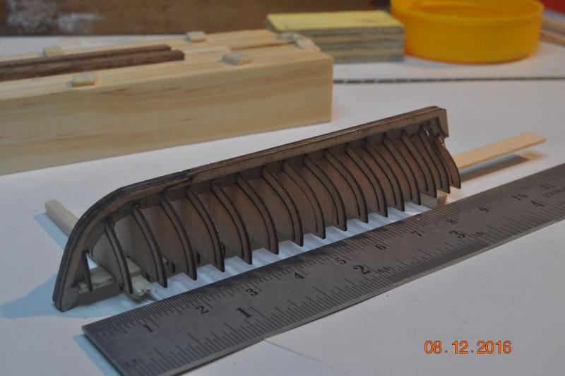
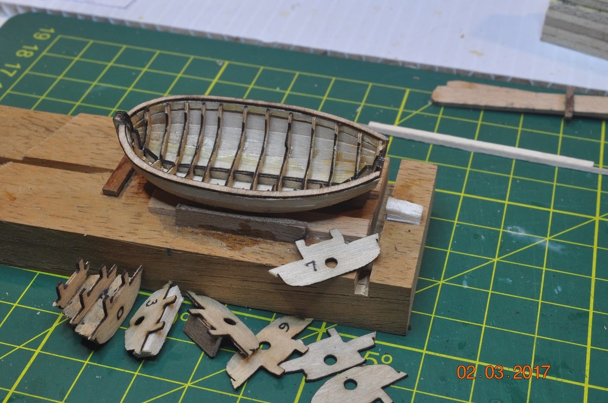
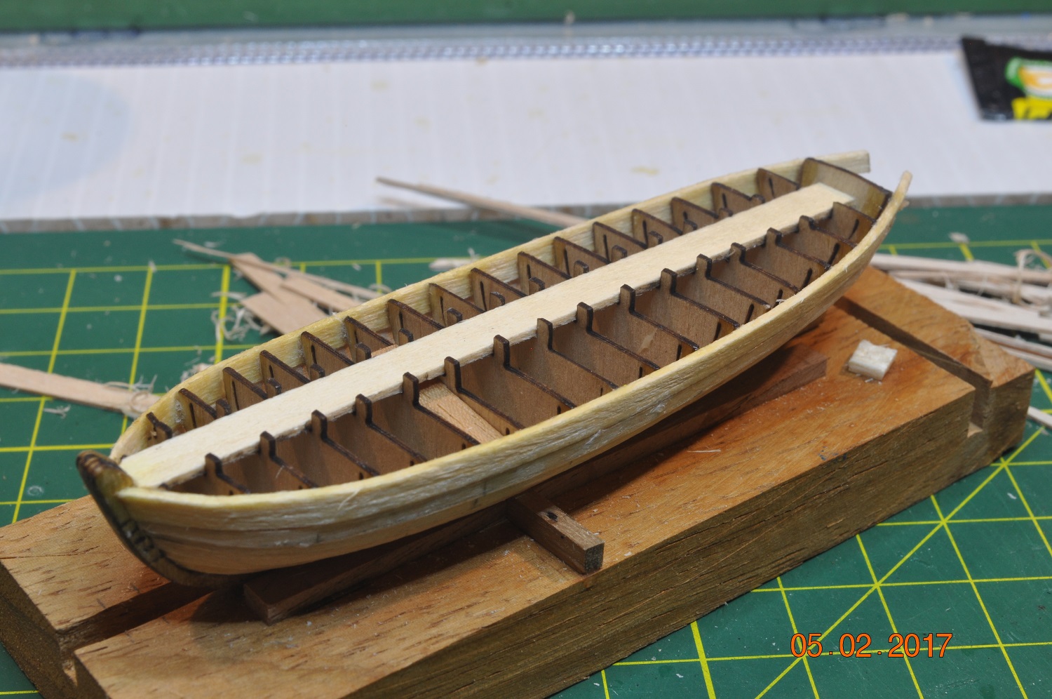
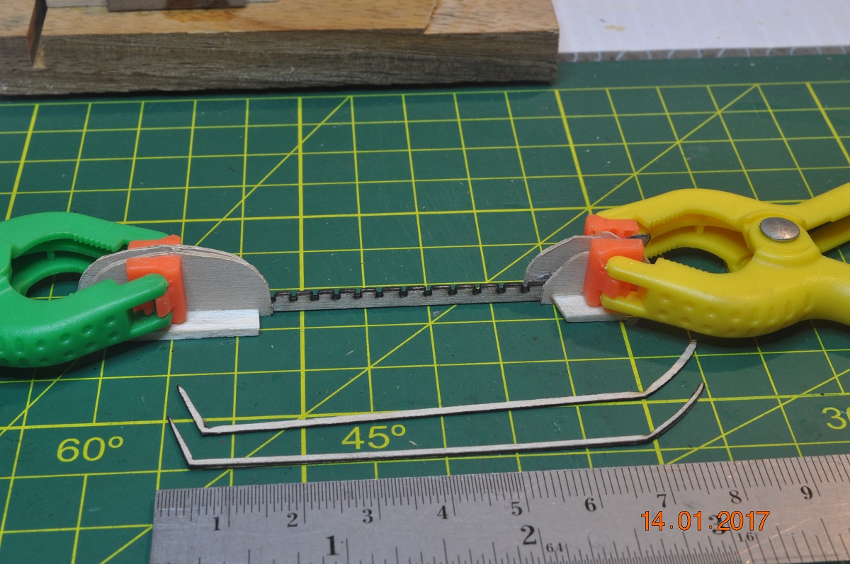
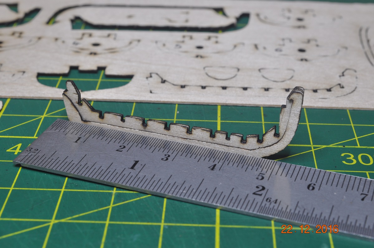
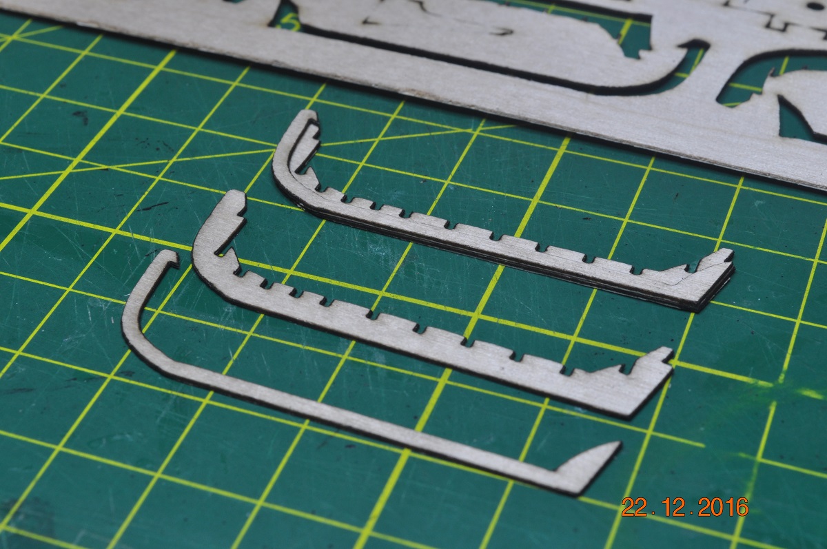
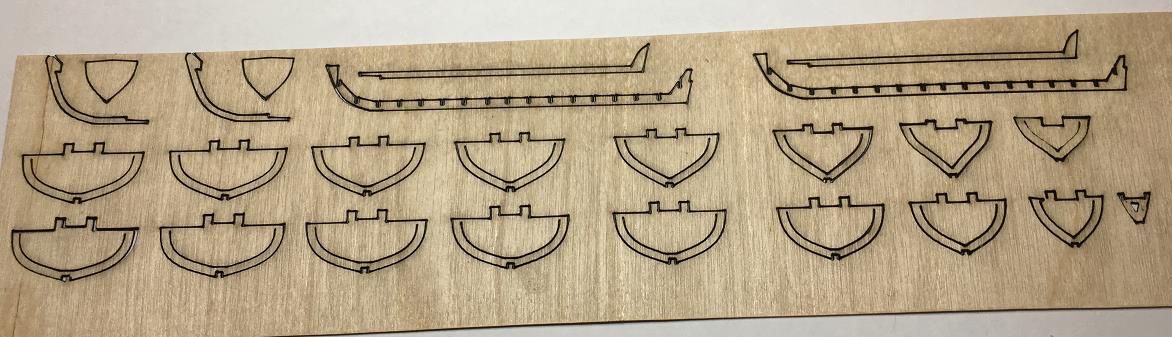
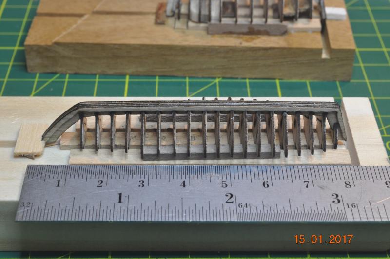
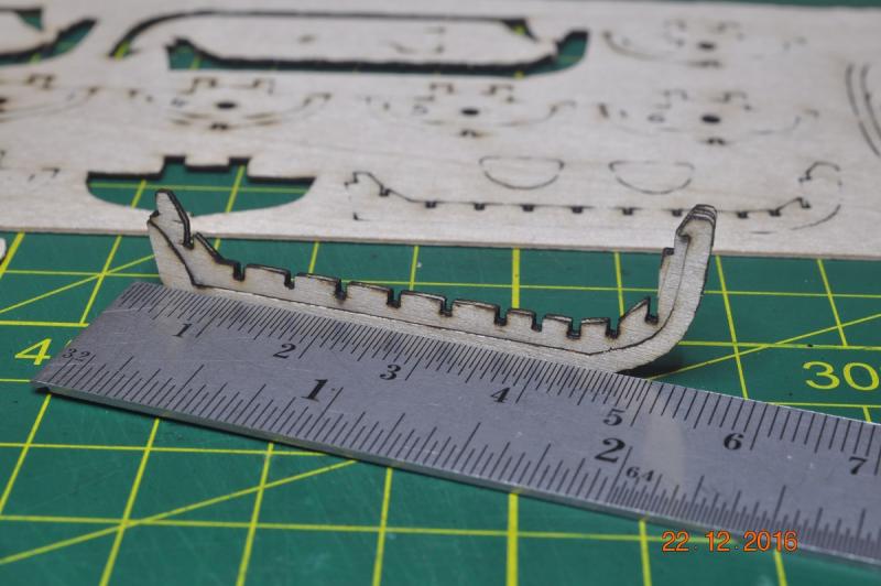
Ships Boats by the Shipyard Skiff Episode 2: The template was laser cut on 0.6mm 3 ply and keel frames assembled as a jig, ready for planking. (part view of the template) Much the same as the Yawl, I assembled the keel and frames as a jig. Keel being glued together. Jig taking shape. The Skiff is just over 83mm long Hanging in their. After the planking is on, the jig pops off the base and the fit-out can start. Dave R

-
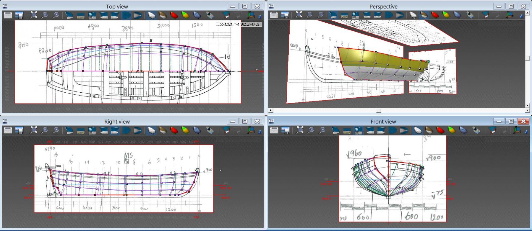
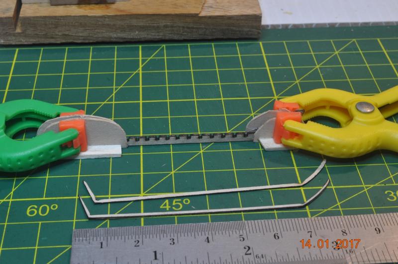
Ships Boats by the Shipyard Yawl Episode 2: The template was laser cut on 0.6mm 3 ply and keel frames assembled as a jig, ready for planking. Part of the Template - keel parts and some of the frames. 2 keels and a "rabbit" keel frame either side makes up the keel -> 4 x 0.6mm = 2.4mm wide The Yawl was 10' long and at 1:60 the keel length just on 50mm long. Jig Jig Jig Dave R


-
Ships Boats by the Shipyard Some/little progress. Pinnace Episode 2: Just added a plank under the gunwale to the Pinnace. And the first plank to the keel. That's all for now as I moved onto the templates for the Yawl and Skiff. Dave R

-
Hello Rexy, I've pulled up a chair to see how you are going on the build. Nice start, and a good catch on the keel out of alignment. Plenty of Endeavour builds on this site to check in on and to seek advice if needed. Good shipyard building. Dave R
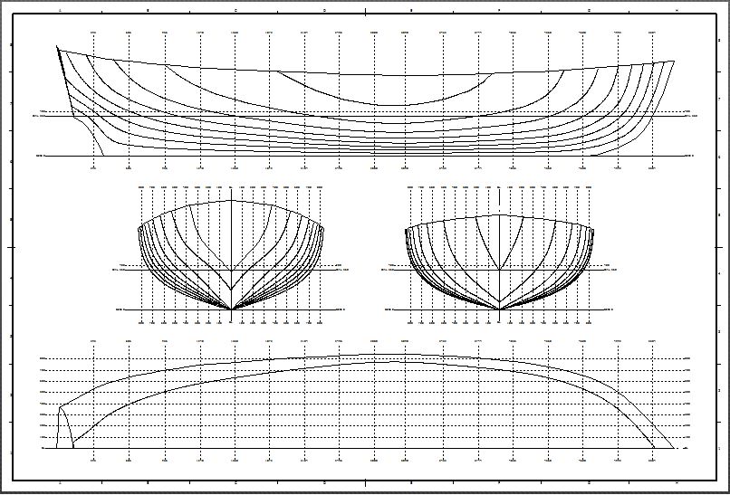
-
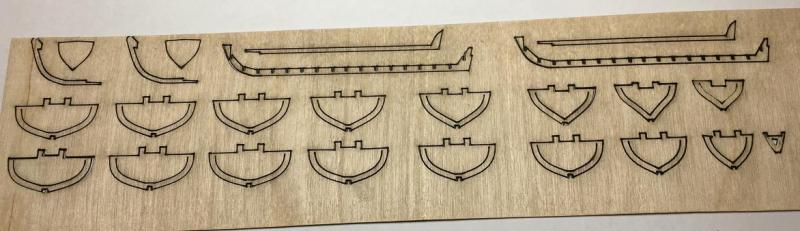
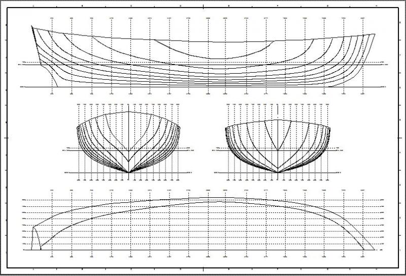
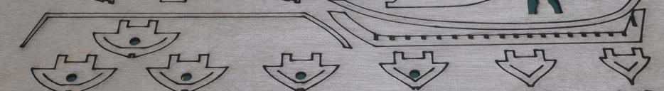
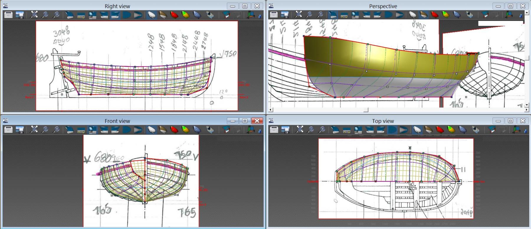
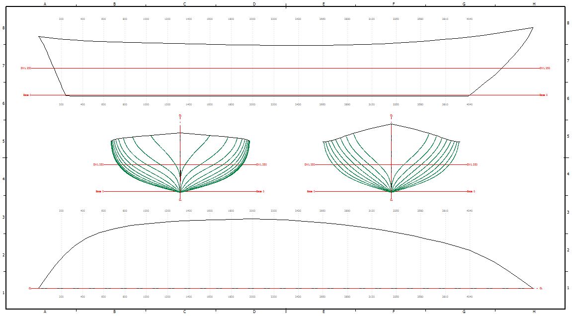
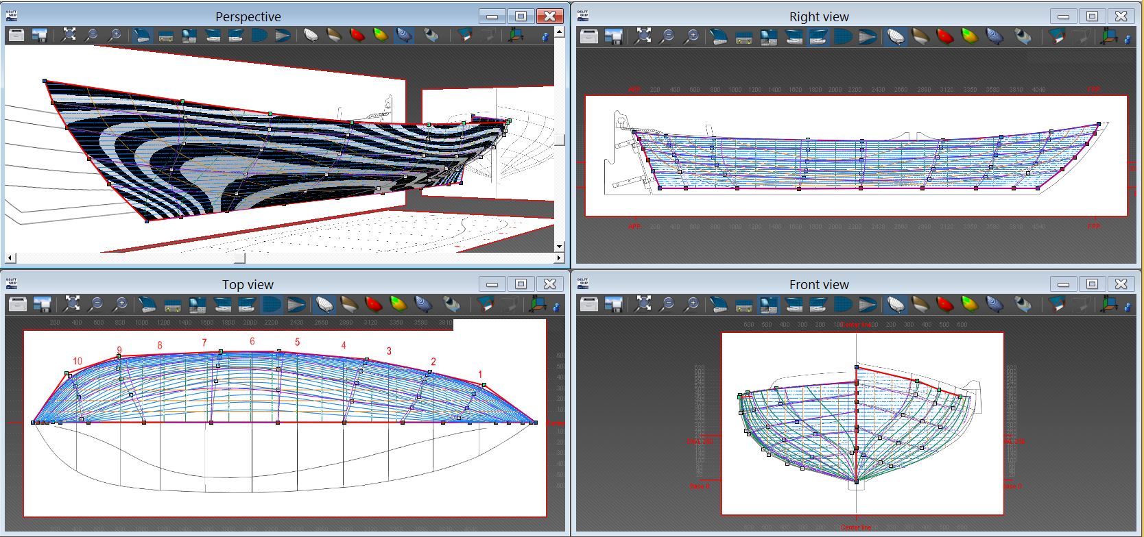
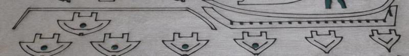
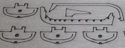
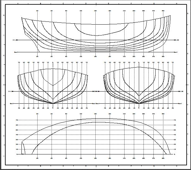
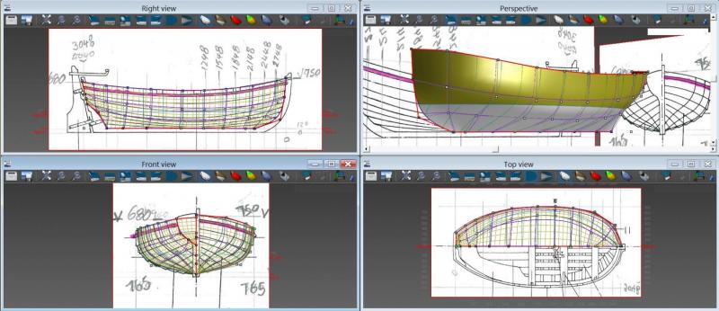
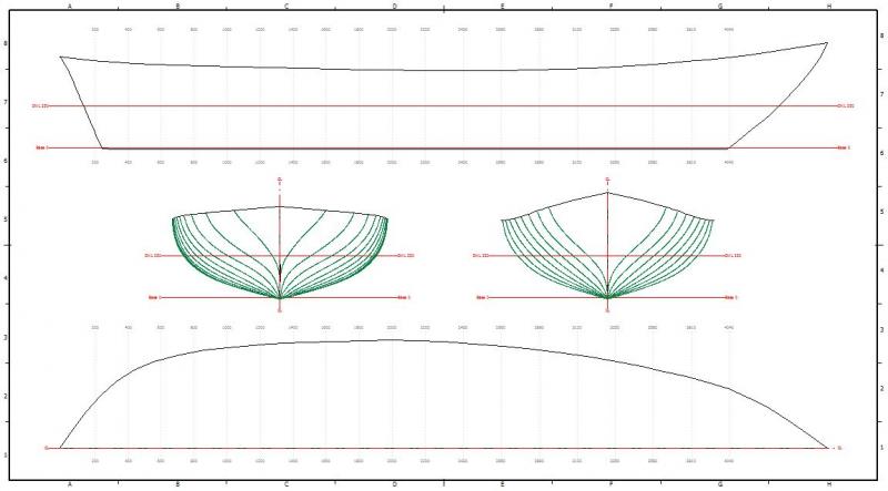
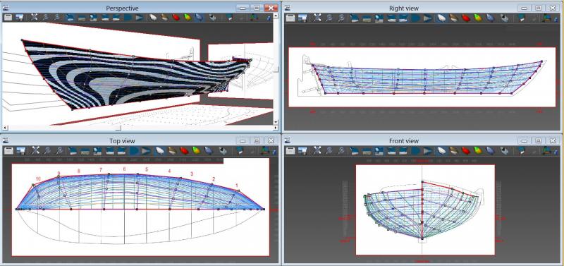
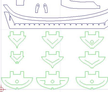
Ships Boats by the Shipyard Some more progress. I have spent(between Xmas shopping and some paying work) some time on the last 2 ships boats. Both to be clinker built on frames similar to the Longboat and Pinnace. The fit-out from the AoTS to follow. I've progressively added a few more items to be cut from the ply. A hole for a rod to go through the frames to keep aligned, that is the intent. (one of our fellow Endeavour builders "Banyan" request) Rudder(laminated), gunwale, knees, seating. See how they fit ! Yawl Episode 1: The Yawl is described by Ray Parkin "H.M. Bark Endeavour" as 10' long, 5' beam and 2' 3" stern post. He makes reference to Mr Banks saying they had no boat on board but a small Yawl.. in Rio de Janerio. I used DELFTship to develop a hull model for the Yawl, based on the lines from the AoTS p133. Again, similar to the Pinnace I scanned the AoTS diagrams, loading bitmap pictures(scaled) into the program, then overlay a manipulated wireframe. The program provides a plot of the hull design that can be used to make patterns. I exported the hull plot as a DXF file. I imported the hull plot DXF file into TurboCAD to further develop a pattern set(frames and keels) for "laser" cutting. Part of the template ready for laser cutting. 3 middle keel lamination's, with a rabbit keel either side. So next is to get this Laser cut onto 0.6mm 3 ply. Skiff Episode 1: In Ray Parkin "Endeavour", he mentions there were two other small boats. However I could not find the size of either boats. A Skiff is depicted in Marquardt AoTS, the length (similar length to the Pinnace ). Seems a bit "long" in consideration of Mr Parkin's, 2 other small boats, smaller than the others ? I've taken a punt and made the Skiff 15' long, in proportion to scale from the drawing. Basically the 4th boat of similar length to the Pinnace. The process is similar to the previous others: Their is quiet a process inside TurboCAD to "pull" apart the DELFTship plot frames to generate individual frames. Each has the top and 2 inside "cuts" added. And the same for the "Keel", creating the "slots" for the frames, and catering for the fore and stern frames that are higher. And a lot of other "bits". All are arranged to minimize ply wastage as much as possible. Part of the template ready for laser cutting. I changed to 2 middle keel lamination's, with a rabbit keel either side. So next is to get these Laser cut onto 0.6mm > 3 ply that I am using. I have a matching PDF file with numbers to each frame to match up to the keel. Then plenty of planking to do and onto the fit-out. Merry Xmas to all. Dave R
-
Chris, Not much "paying" work at the moment, time for fun things. Some late nights on this stuff though, I get so involved, time slips by. It also helps I have an extensive sailing, yachting and CAD background. Compared to others. I believe I take my time. Dave R
-
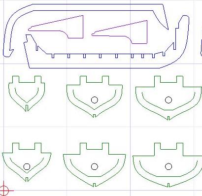
Ships Boats by the Shipyard Some more progress. The Pinnace will be another clinker hull built on frames similar to the Longboat. The fit-out from the AoTS. Pinnace Episode 1: I used DELFTship to develop a hull model for the pinnace, based on the lines from the AoTS p132. This process involves scanning to AoTS diagrams, loading bitmap pictures(scaled) into the program, then overlay a manipulated wireframe. The program provides a plot of the hull design that can be used to make patterns. For the Longboat I hand cut all frames and keel from 0.6mm ply and using a scaple blade. Very time consuming and not 100% accurate. See my previous log on this. For this boat I wanted to create a set of patterns and then Laser cut them on the 0.6mm 3 ply. I exported the hull plot as a DXF to load into TurboCAD to further develop a pattern set(frames and keels) for "laser" cutting. Being the first time, it took a lot of time to develop the patterns to a stage for laser testing. I am fortunate to have a local source who has a laser cutter. After some trial runs, this is the end product of the laser cut frames and keel elements. Next the assembly of the elements to form a hull frame/shape. This has been a big learning curve, and I must thank Pat(Banyan) for his advice and thoughts. I plan to do the other 2 boats(Yawl and Skiff) in a similar manner, applying some upgrades to the laser pattern design from what has been learn't through this process. Ya gotta have fun to do this..... crazy.... Dave R