HOLIDAY DONATION DRIVE - SUPPORT MSW - DO YOUR PART TO KEEP THIS GREAT FORUM GOING! (Only 13 donations so far - C'mon guys!)
×


DaveRow
-
Posts
691 -
Joined
-
Last visited
Content Type
Profiles
Forums
Gallery
Events
Everything posted by DaveRow
-
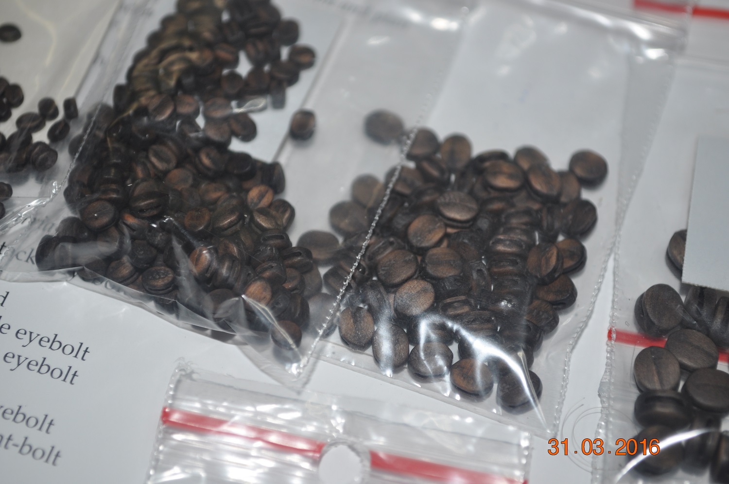
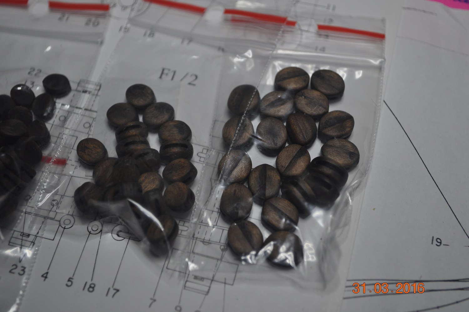
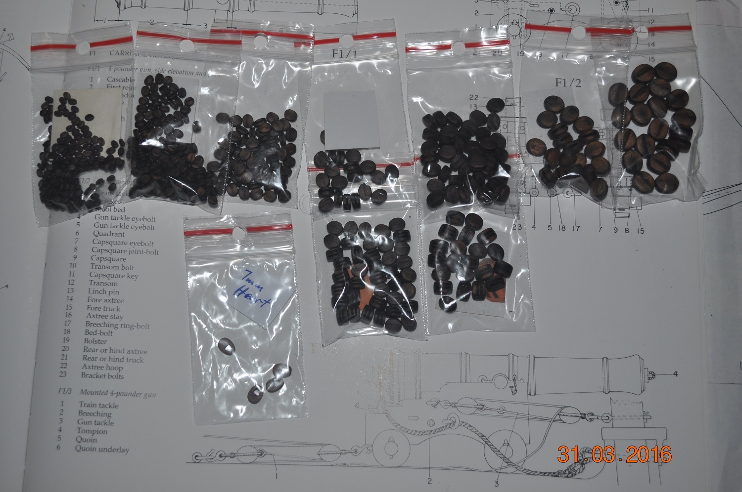
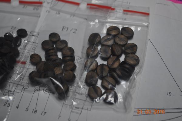
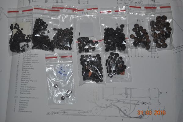
 In the Shipyard Office, Getting organised for the "Rigging Phase" Our second shipment of Blocks from Mirek "Classic Models" arrived 2 days ago. Over 520 blocks in the packages. They do look a lot better than the kit ones. Dave R
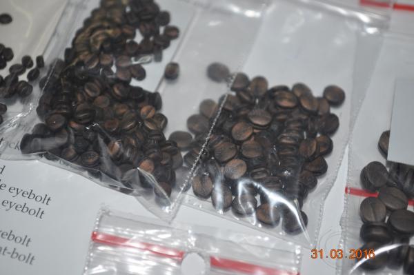
-
Hi Chris, Have not seen this manual before. Had a quick look, very interesting, and will have a closer look soon. Thanks for sharing. Dave R
-
The sails come up very nice Ron, I decided not to do sails on my Endeavour, moored at dock version. Dave R
-
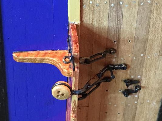
Hi Slog, The washer was a purchased brass one. Very small, one of many I purchased some time ago with miniature 00-90 hex head bolts and nuts. Dave R
-
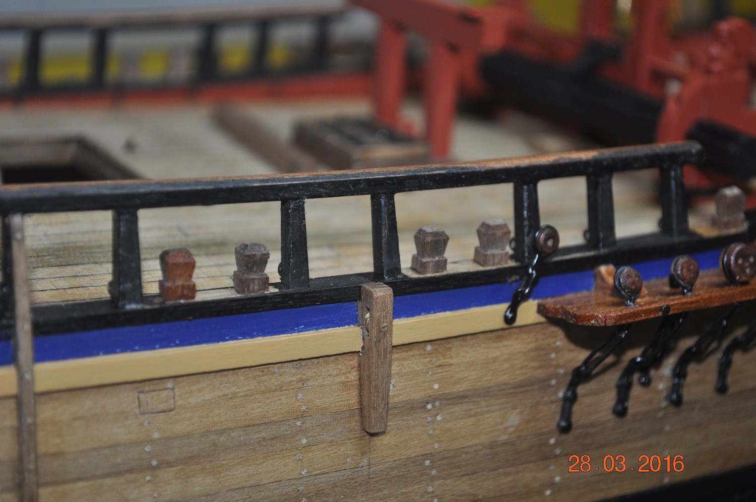
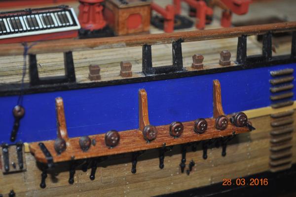
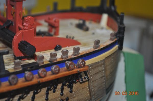
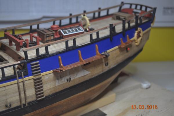
Shipyard Update: You have got to love 4 day weekends(Easter), time to get into some modeling. Over the last 2 days made the 34 Timberheads and fitted/glued in place. Still not ready to paint the roughtree rails, cleats to mount and probably get scratched over the next 12 months doing the rigging. I'll paint the Timberheads though, as I can get to them now. Dave R


-
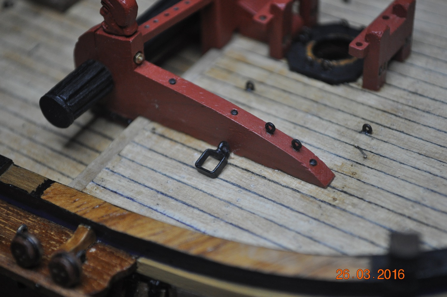
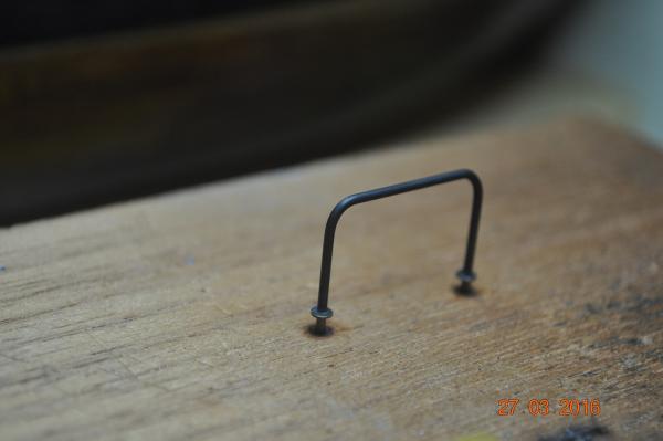
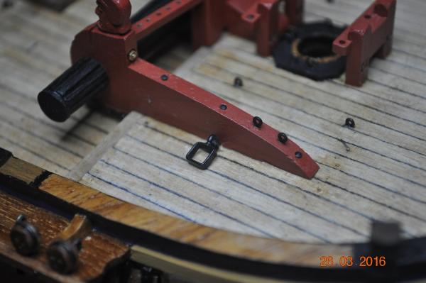
Shipyard Update: Iron Horse fabricated. Small weld job of 2 brass washers to some rod to form the horse. Blackened and fitted over the back of the Rudder stock. Dave R
-
Hi Greg, Now that would make some sense. Only put it out to lift an anchor up. Well I have a spare one then. Thanks Dave R
-
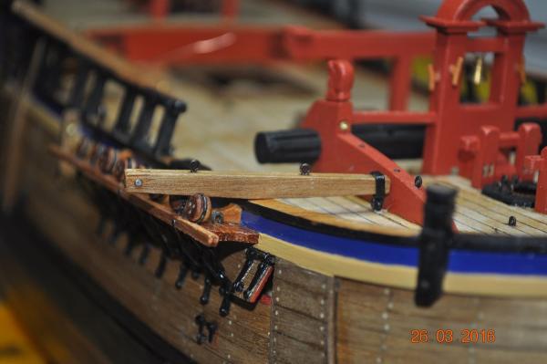
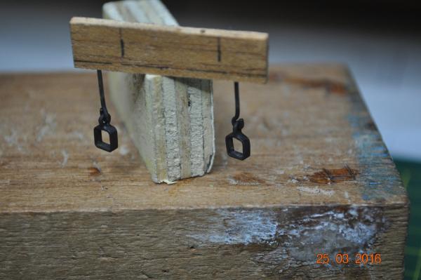
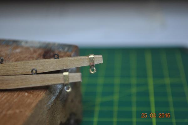
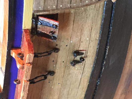
I had made the 2 Fish Davits a while back. Since I now have a pretty good method of welding, had a go at the square metal rings and eye for each. I should of taken more pics of the eye to the ring. I cut a eye bolt short. I formed up the square ring out of flat brass with the join on the bottom(slightly pushed out). The joint was welded, then drill a oversize hole for the eye pin to go through through the joint(even though it split, not a problem) Finally the pin, in place in the hole, weld it in place, with the joint closing up as well. Hope these 2 picture shows that. Davit bracket(Stbd) in place: Davit over the gunnel: Dave R
-
Thanks for checking in on the build fellas. Don, Chris and Greg, the chains were a big push(effort) to get each made and in place. And yes an assembly line, like Mr Ford work out, only on a smaller scale helped a lot. I must thank Pat(Banyan) for putting me onto the resistance welder. It sure makes a neat joint when it all comes together. Their were a few failures along the way, not all plane sailing they say. Maybe another post for them ? I've got the shipyard making the cover strips that go over the length of the channels to cover the cats eye shanks at the moment. Cheers Dave R
-
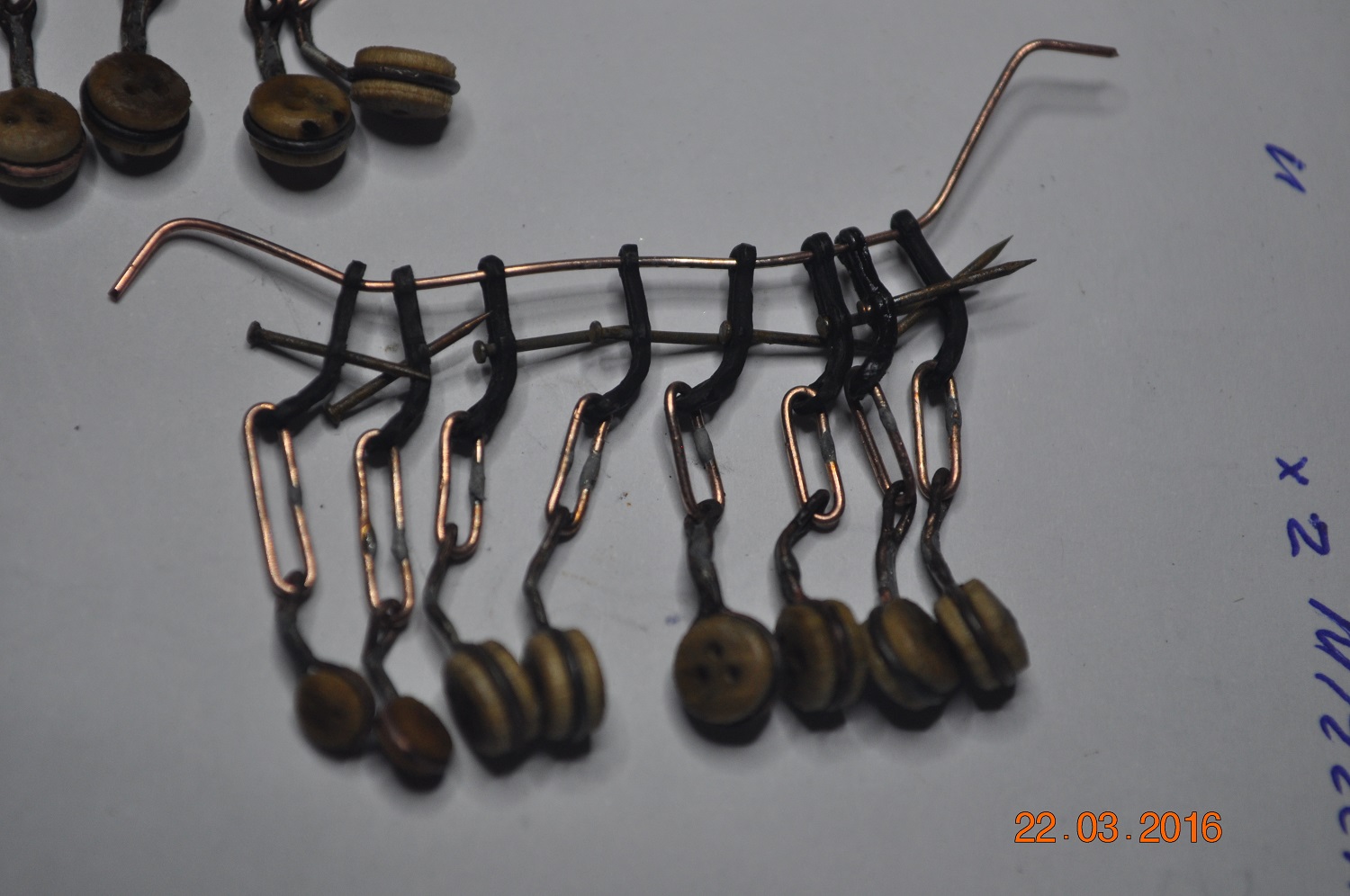
Starboard Channel chains and shroud dead-eye assemblies. Have attached the starboard shroud chain assemblies. A close up under the Main channel. I like the angle shot. This is what the chains looked like after a clean with Hydrocloric acid. The welds were done with a resistance welding system. does a neat job. Dave R

-
Mr Dash, The hull has come up a treat. Nice an clean looking. Probably a shame to add fittings on it eh ! PS. You probably have something sorted out for mounting when finished ? I didn't, and only recently(with deck fittings on), drilled 2 long vertical holes in the keel for fixing to a cradle or spigots. Not sure which way, but the holes are now their. Dave R
-
Back Stay Chains Fitted the 3 x port side back stay chains. Fore Top-Gallant: Main Top-Gallant: Mizzen Backstay: Dave R
-
Gee Pat, Those swivel guns sure look great. Will look fantastic mounted on the posts. Dave R
- 517 replies
-
- 3
-

-
- Endeavour
- Artesania Latina
- (and 1 more)
-
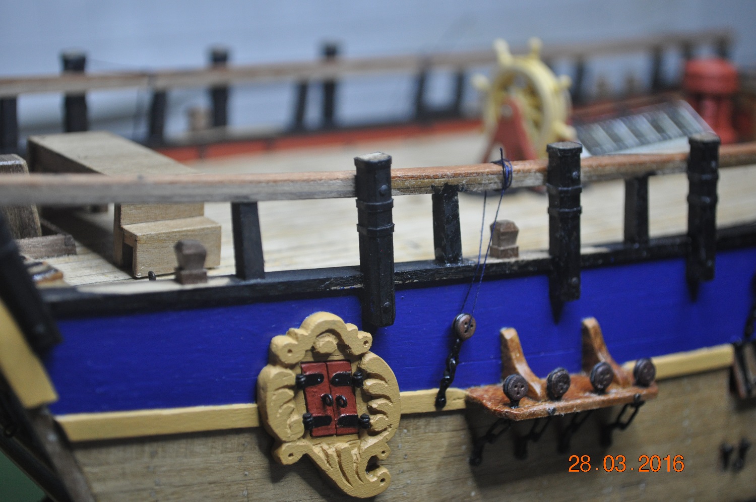
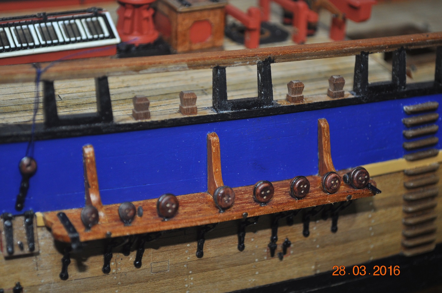
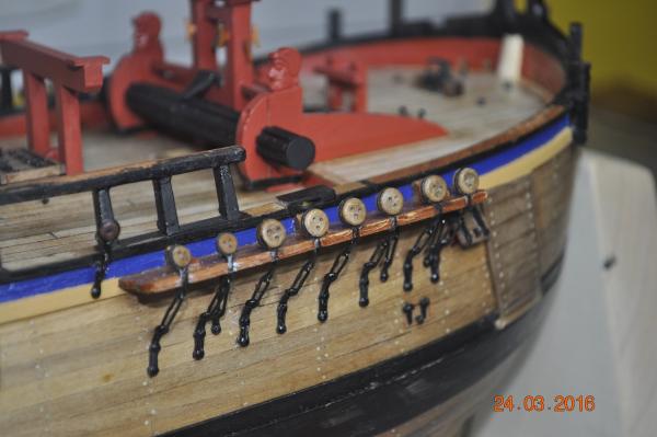
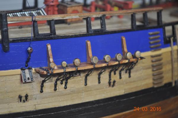
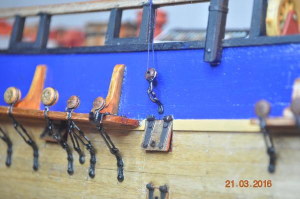
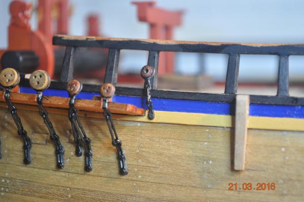
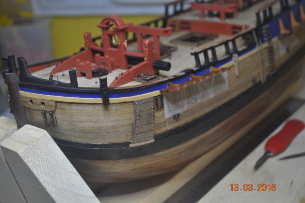
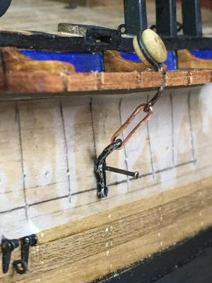
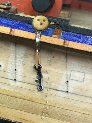
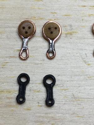
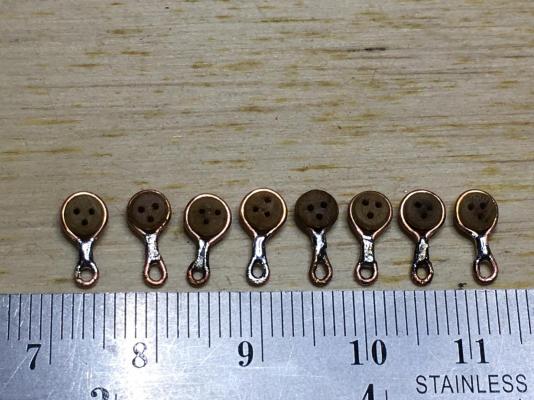
Port Channel chains and shroud dead-eye assemblies. After a lot of chain making, minute welding, cleaning, blackening, painting, aligning, gluing etc. The port Channel chain assemblies are in place(finished ?) apart from the cover strips(which I plan to make and pin in place in case I need to work on the chains down the track) I have string holding each dead-eye up, some CA glue applied in the channel slot, just beneath the dead-eye. Port Fore Channel Port Main Channel Port Mizzen Channel I now apply a coat of clear to the metal items to protect from scratching. Note: I am very disappointed in the "3 x hole" pattern of some of the dead eyes. I used the kit supplied large ones and smaller ones purchased. Only 50% are spot on equal lateral triangle, the others ? you'll see. Backstay chains and thimbles, dead-eye I have made the Port and Starboard for above. Here they have been cleaned(hydrocloric acid) before blackening. Onto the Starboard side next. All the main parts are made, just hours of assembly to go. Dave R
-
The shipyard is working on the Shroud Chains. I am well advanced, with most of the main channel chains made. Couple of earlier shots of the inner Mast Tackle eyes(I believe that is what they are for). There is a third eye for the Tye Tackle on the Fore and Main channels. Hard not to scratch the metal, however they should come up with a bit of touching up. Dave R
-
Hi Bill Thanks for looking in. I've ordered more of each for other "things". 700 seems a lot, but all was done by hand and pulley purchase in those seafaring days. Dave R
-
I've PM you.
-
The blocks in my Corel kit were the square ones as well. You deserve a medal for all that sanding to the blocks. Something I did not intend doing, hence the big purchase of CNC blocks, they should look really great in the rig. I worked out each was costing approx. 0.32 AUS cents each landed to my doorstep from Poland. Compared to some of my other purchases, that is quiet reasonable. I was going to get some of Chucks 3.5mm Boxwood cleats to check them out. Save me some time making my own, my fingers do enough small work on plenty of other "jobs" for the ship. Dave R
-
Hello Shipmates, In preparation for the masts and rigging, I have been wishing to order all the rope and blocks in 1 order for each(cut down on postage). I have had little success from attempts to see what volumes others have used. The blocks(those cheap square ugly things) and rope that came with the kit, I am not happy with the quality. So I used Steel's "STEEL - Progressive Method of Rigging Ships" and translated the data into a spreadsheet(I posted this task some several months ago) The table below is the outcome of hours of work. I came up with for the number, size and type of blocks for the Endeavour Rigging(standing and running). Have ordered the lot, plus some extra. It is a bit short of the 700 mentioned below. Blocks Size 2.00 3.00 4.00 5.00 6.00 7.00 8.00 9.00 TOTAL 670 465 Single 2 186 169 62 10 26 4 6 103 Double 14 32 10 33 14 12 Hearts 4 0 24 2 0 0 0 90 Dead Eyes 66 0 24 0 0 0 0 I have an article called "Rerigging Endeavour Part 2 by Anthony Longhurst", ANMM leading-hand rigger and shipwright. It mentions the Endeavour has nearly 700 blocks, eight kilometres of running rigging, 30 spars (masts, yards and booms) and 10,000 square feet (930 m2) of canvas that make up Endeavour’s sails. I am short 30 ! I'll find them I am sure. I am currently working from "Steels" to calculate the amount of standing and running rope; size and length to order. Dave R
-
Steve and others. I bought a pair from Jaycar - they are great. Thanks for sharing. Dave R
-
Hi Pat, Time will tell, I have brushed against the hull, rails transom a few times, everything is fixed in place, mostly with epoxy glue, strong as. The boat boom hardware, fixed on very well, their would be damage if I tried to remove them. I am really happy with the channels though, being glued into the slot I allowed for in the sheer strake, and the knees > they are fixed in really well. Dave R
-
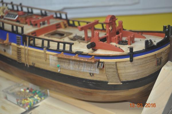
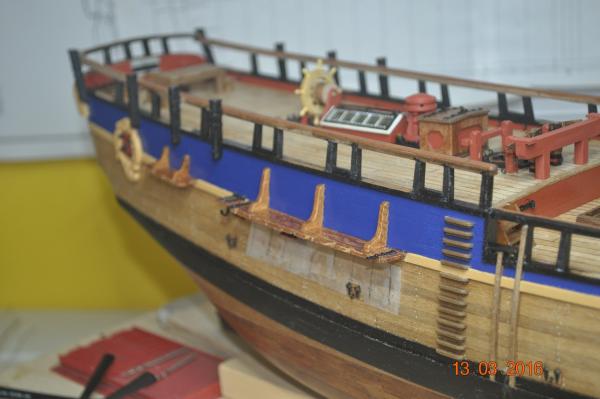
Some shots of the Port and Starboard sides of the hull. I went over the blue and yellow painted sections on the hull and touched the colors up. I am leaving the Channels as timber, not painting them, as the timber against the blue and yellow is a good contrast. Next; more work to create the shrouds(wire, loops cats eyes, etc.) Dave R
-
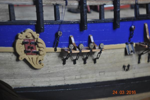
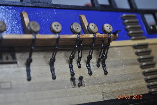
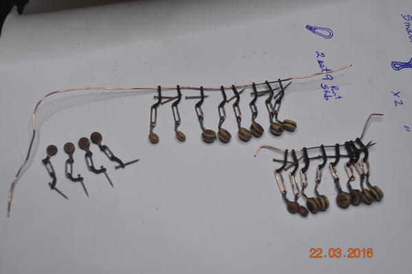
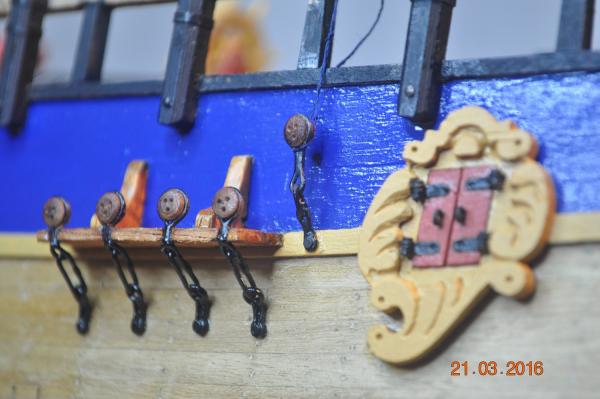
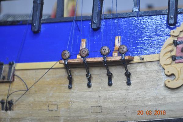
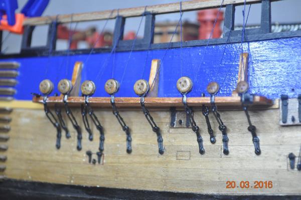
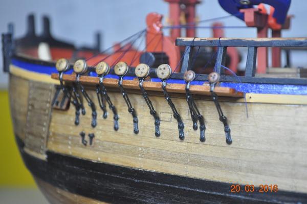
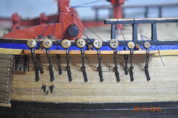
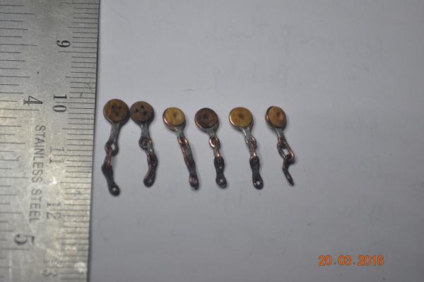
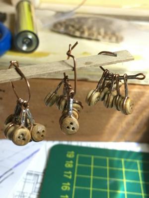
Chains and links to the channels Still working on the chains and links. Lots to make. Fore and Main Cats Eye done - 3 of the 4 sets(of 6) hanging. Still to make the 4 sets of 2 smaller ones for backstays) Settled on this arrangement for the Fore and Main Channel Chains. It is probably the first metal item(Link) that came with the kit(and likely the only) that I have used. Mizzen Cats Eyes(2 sets of 4) and Link(cut down of the main ones) Smaller units, bit more fiddly to handle. I have been using the resistance welding unit for the solder joints. I tried 4 different solders on test joints. If I am right a 60/40 solder Tin/Lead holds very well. So that is what I have used. Most of the Cats Eyes solder will be hidden by the channel cap, so not a problem hiding it. Dave R
-
Great start Phill, Planking has come up good. I just finished reading the life of William Bligh in the Book "Bligh, Master Mariner" by Rob MundleWhat a mariner he was. Dave R