DaveRow
-
Posts
691 -
Joined
-
Last visited
Content Type
Profiles
Forums
Gallery
Events
Everything posted by DaveRow
-
 Blacky, Their is a saying the final paint job is only as good as the preparation underneath. So my suggestions are: - Check the hull is fair, all even curves - no dips as these will show up on the final skin - fill any dips, sand any highs if enough "meat" to fair it out - plan out how you are going to lay the planks from bow to stern. Lining out the widths and where you are going to show the joins - their is a lot of tapering of planks, dropped strakes(planks at bow) and new ones to add in(Steelers, usually aft) - do not force a plank into place, each should lay in the space - bevel at least one(1) edge(top) so no gap exists when they laid down Confused, ? i was, but plenty of reading, prep. will help and get you their.
 -
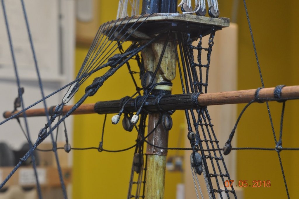
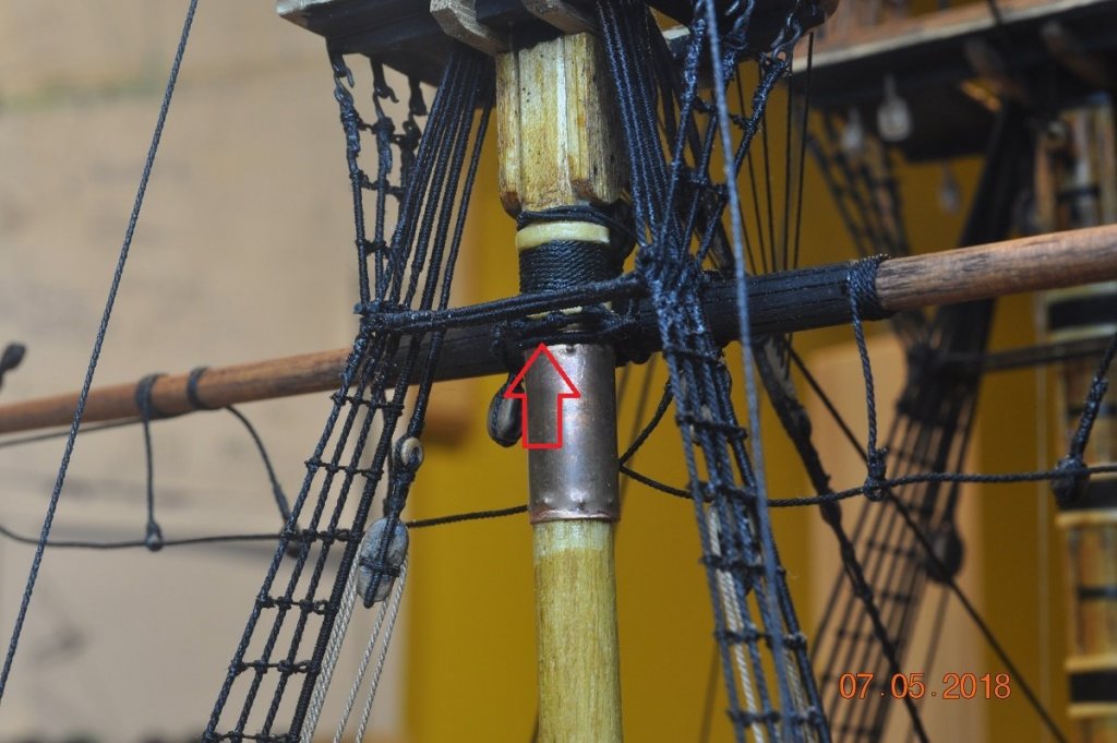
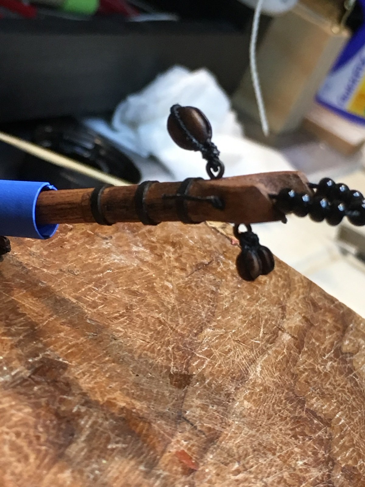
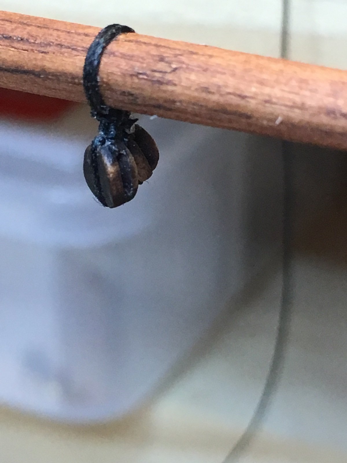
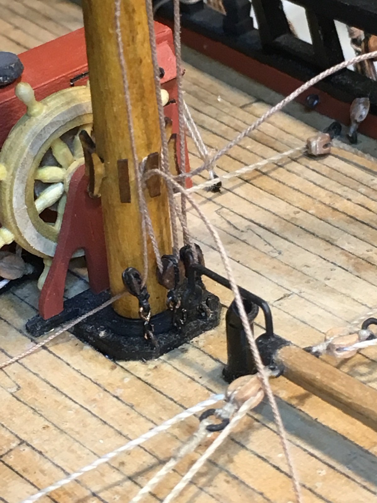
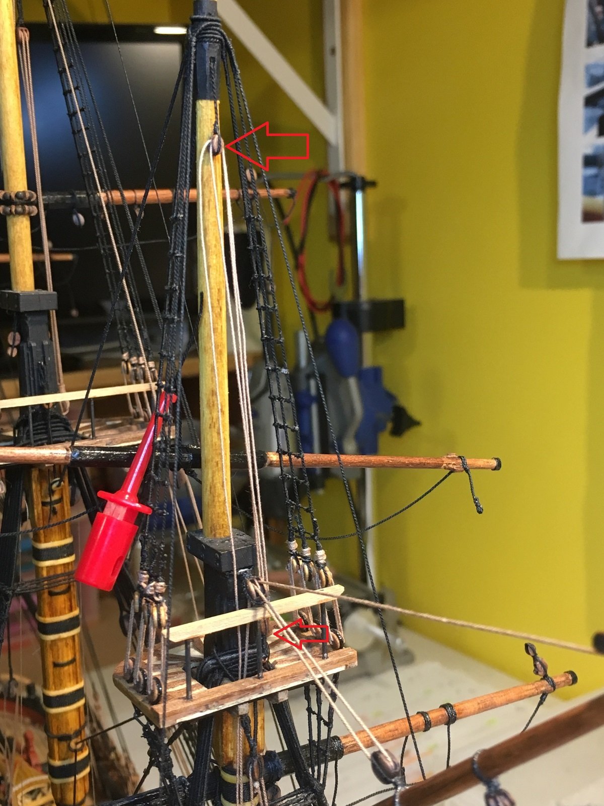
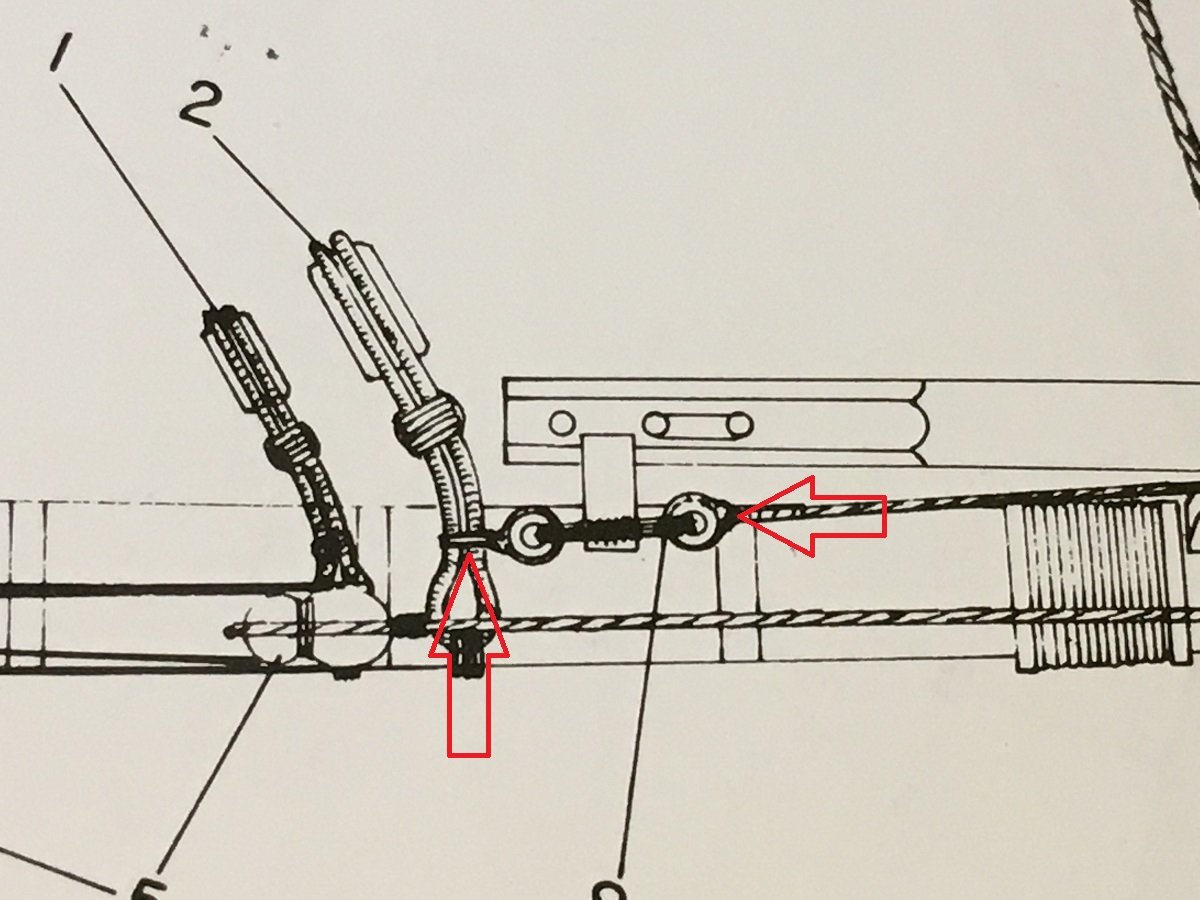
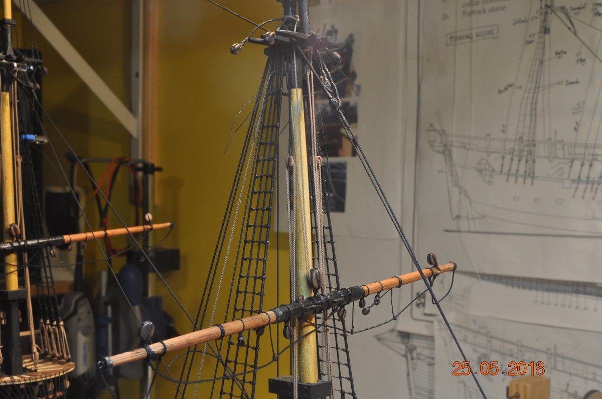
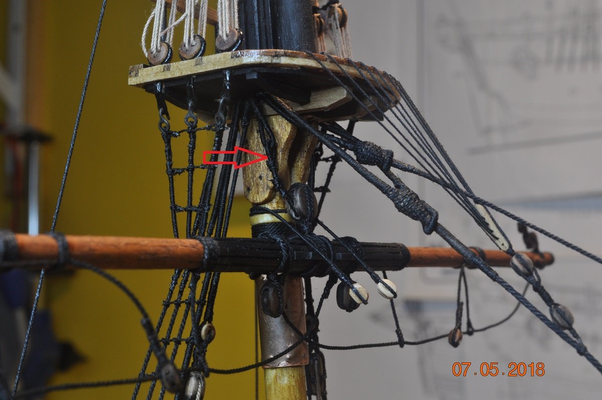
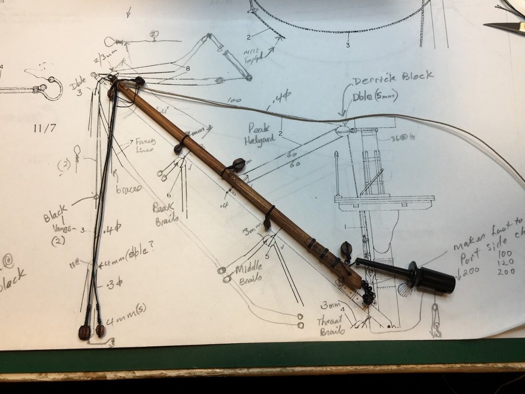
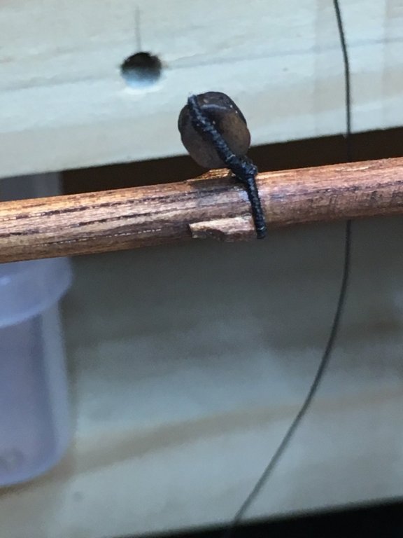
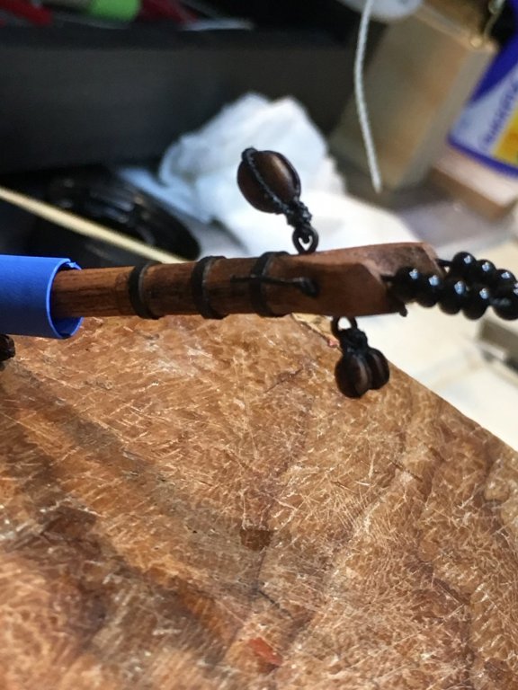
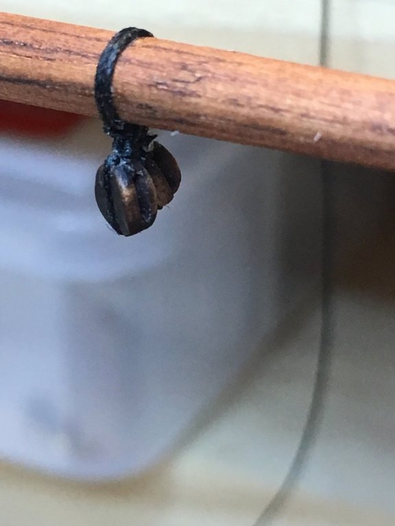
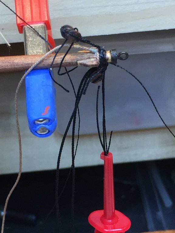
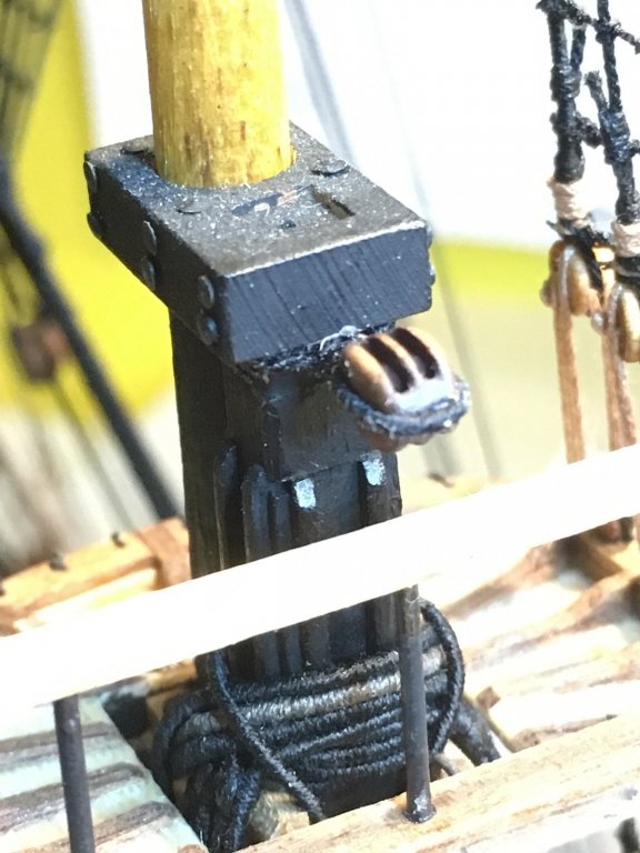
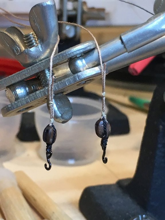
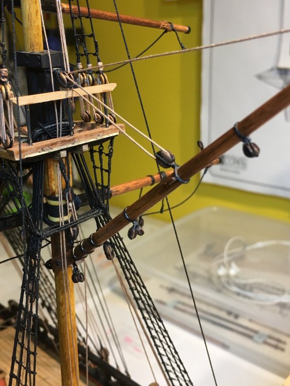
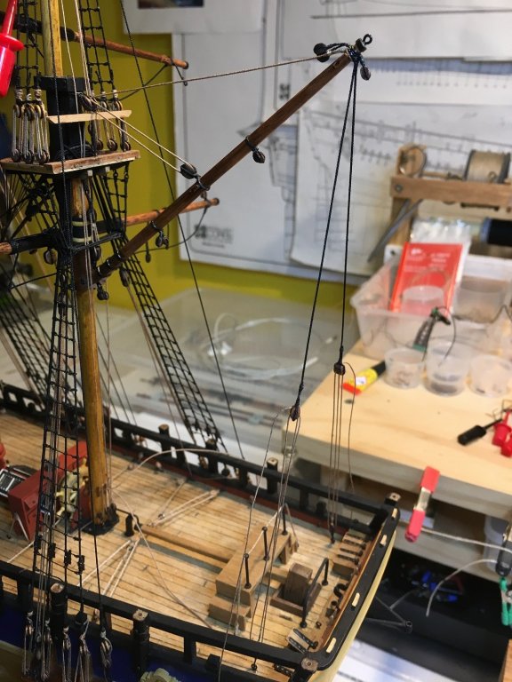
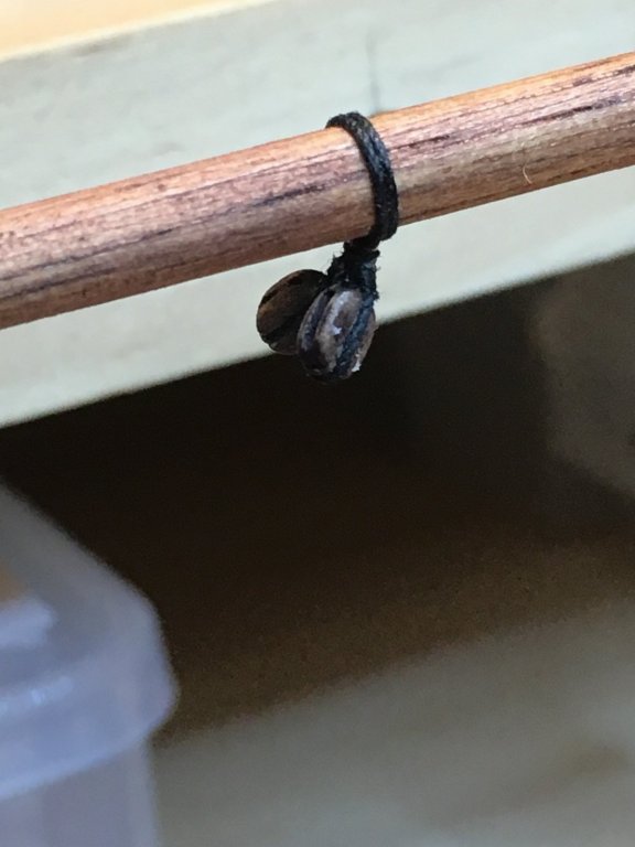
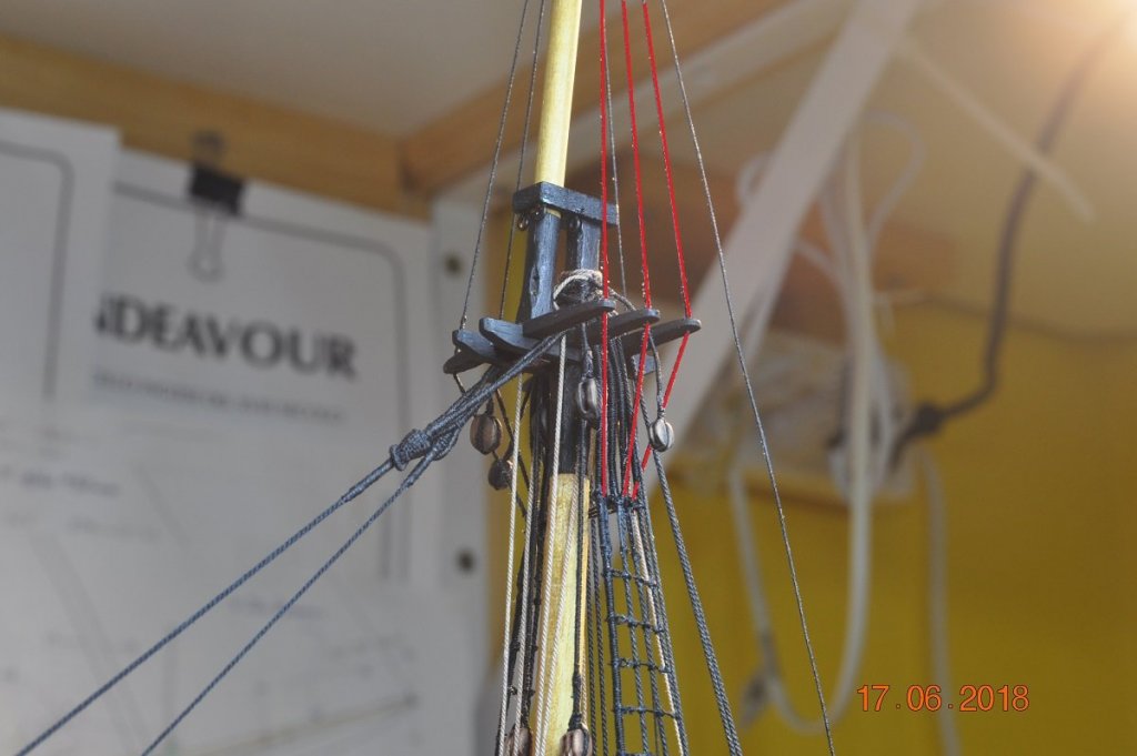
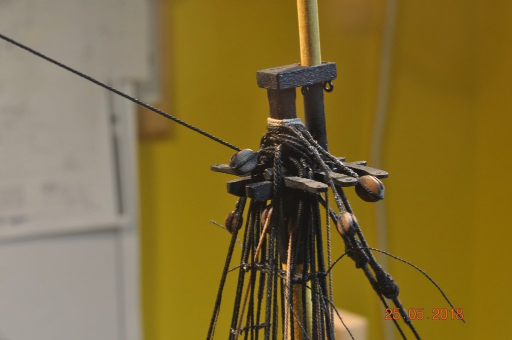
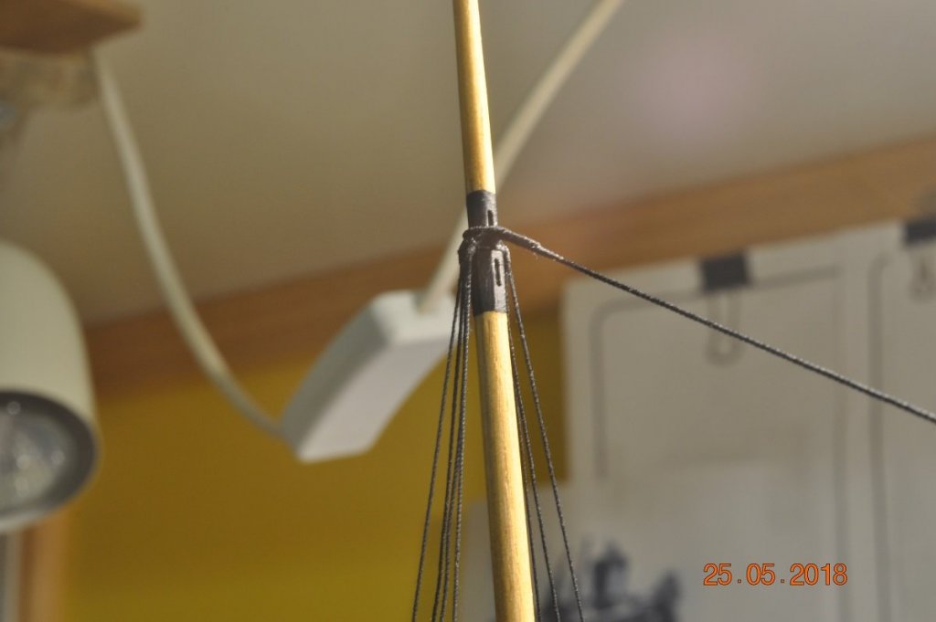
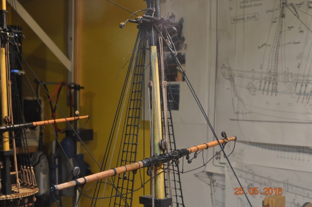
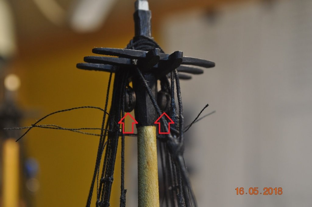
Shipyard Update: We have moved onto the Mizzen Gaff and TopGallant Yard. The Gaff has a number of blocks and slings on it, all providing the hoisting, Vang, bracing to the TopGallant yard, Brails to the sail. Below is Gaff nearly ready to hoist to the Mizzen. Below picture of the components added to the Gaff: Fitting the Parrell to the Gaff beak. Top the 4mm JeerBlock and below the 2 x 3mm Throat Brails Mid and Peak Brails Blocks 3mm Derrick Block(4mm) Gaff Paek; a lot of ropes and blocks attach to the end. Mizzen Topsail Yard Braces(2 x 3mm) topside Fancy Line blocks(2 x 3mm) underneath Vangs Slings(2) Peak/Derrick halyard(1) - single lighter rope on top Derrick 4mm DoubleBlock is lashed to the Mizzen-cap Halyard through the Derrick Blocks(4mm) JeerBlock(4mm) with sling, around and under the Mizzen Cap. The AoTS had a fixed sling for this. I replaced it with Jeer Blocks like the Replica has. Made sense so the Gaff can be raised more easily. Vang - lower 4mm blocks with hooks Vangs(2) falls fitted to end of Gaff to eye-bolts in the quarters TopGallant Tye fall: top end rope runs through a hole under the shrouds with a 3mm double block(top red arrow), lower end 3mm block hooked into an eye-bolt(lower red arrow) The Mizzen Mast base - Halyards and Jeers running through blocks Bit of tidying up to do, but nearly their. Add the Fancy and Brails lines. All up it's taken me a couple of weeks on/off to get it all together.


-
Thanks for looking in Rod, I have learn't so much during my build, with many thanks go to others who have shared ideas and techniques. To give back I do the same, in hope it is worthwhile for others for their builds.
-
Hi Rod, Your Endeavour is coming along very nice indeed. I keep an eye out for updates all the time.
-
Hi Vin, Just found your build log. Going well. Will keep a sailors eye out on it. Sent you a PM re the blocks.
-
Hi Blacky, I can see the planks appear not to have any tapering in them ! Being the first layer, not really have to be. However in my opinion by staggering and running the planks bow to stern, the model will get a nice even hull shape. A couple of articles for interest I gathered, explain the planking techniques used if you wish to have a read whilst on holidays. The "Bluff Bow Planking" is actually an article based on the build of the Australian replica of the HMB Endeavour. The others, a general how to plank. My Endeavour was the first time I had planked a hull. So I used the first layer as a trial run, before the second planking layer. Lining Off your hull for planking.pdf Planking Project Beginners.pdf Bluff Bow Planking.pdf
-
Hi Blacky, Although still working on the hull, you are probably at the point of considering on what your model is going to look like when finished. Whilst some timbers are left clear varnish/lacquer, other may be painted blue, yellow, red or black seem to be the most common for the Endeavour. For my Endeavour: I stained the underside of the hull to waterline, applying a coat of clear lacquer. It is great to show off one's workmanship and leave some items timber grain/color, maybe with a touch of paint. Some timbers painted black, as long as the grain is tight, comes out looking nice. Some doesn't matter as they are painted over with a scheme of colors. I purchased extra timber strips to make a lot if items as they wore not provided in my kit. For inspiration. Have a look at other Endeavour's on the site, see what finishes have been used. Hope you don't mind my rambling on.
-
Hey Rod, I used to use a lot of CA glue on the rope rigging. But it does dry brittle. Can be dissolved with Acetone, but tricky to use. I now use mostly a 50/50 PVA/water mix. It tales a little while to dry, but looks better. Still can dissolve with water later if needed. Build coming along nicely.
-
Hi Blakey, Good to see another Endeavour underway. Lots of other builds to refer too on this site if you need help with the finer details. Will pull up a chair and keep an eye on your build log. All the best.
-
HMCSS Victoria 1855 by BANYAN - 1:72
DaveRow replied to BANYAN's topic in - Build logs for subjects built 1851 - 1900
Very neat work on the Anchors Pat. Your skills are really been honed on this this project.- 993 replies
-
- 5
-

-
- gun dispatch vessel
- victoria
- (and 2 more)
-
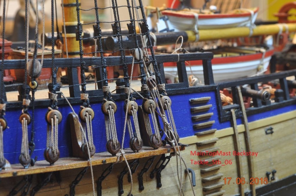
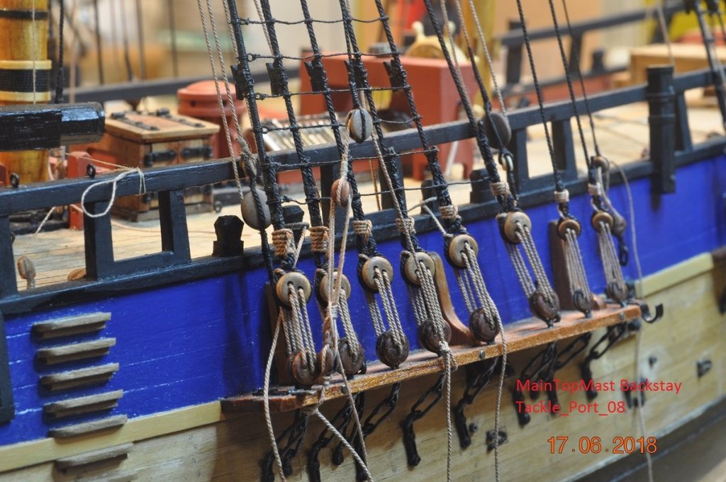
Shipyard Update: The shipyard has been on a go slow. Too many distractions for the owner(me). Managed to get the Top Gallant Shrouds and Backstays on Fore and Main Masts. Pre-rigged the above onto the Top Gallant mast sections. Then fitted onto the respective Top Masts. Below: 1 set of two(2) Top Gallants for Main and Fore Masts. Below: Pictures of shrouds tied to Top Mast stays. Below: Mast Backstay Tackle Also have now rigged all 4 of the Top Mast Tackles to the channels. Each Picture has location on it. Next to finish the Fore Top Gallant Shrouds. So much fun tying these in mid air, keeping the mast vertical and shroud tensions the same.


-
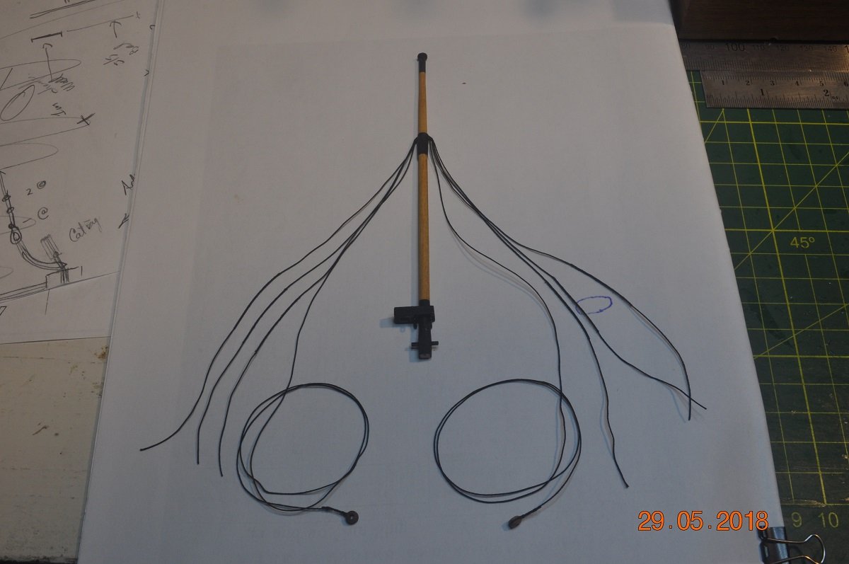
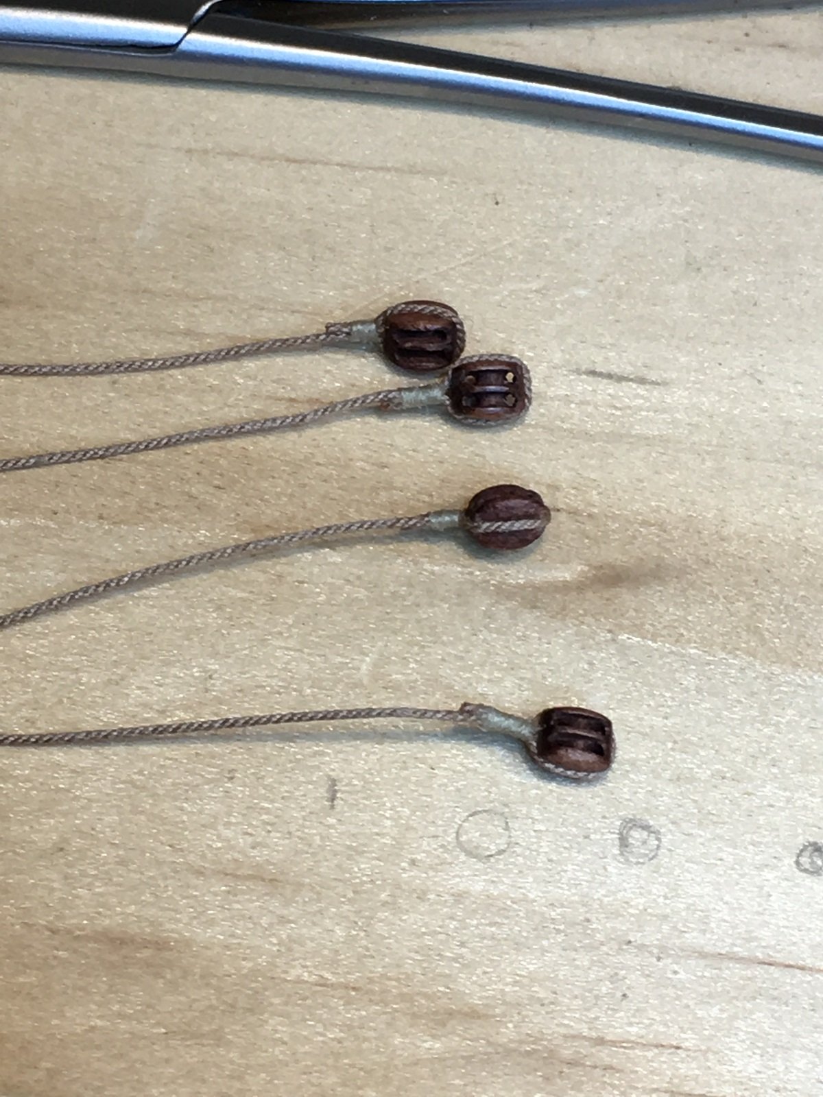
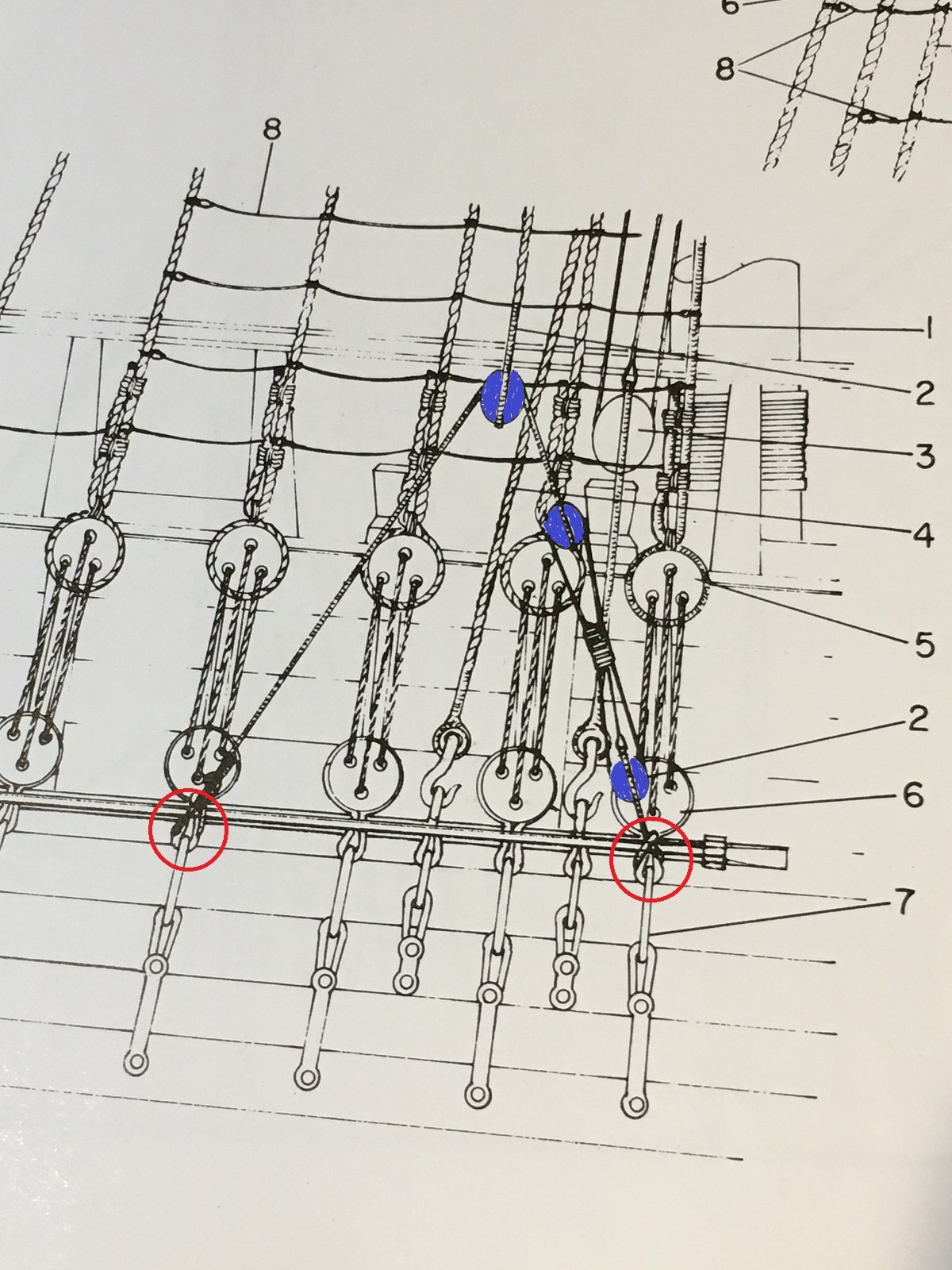
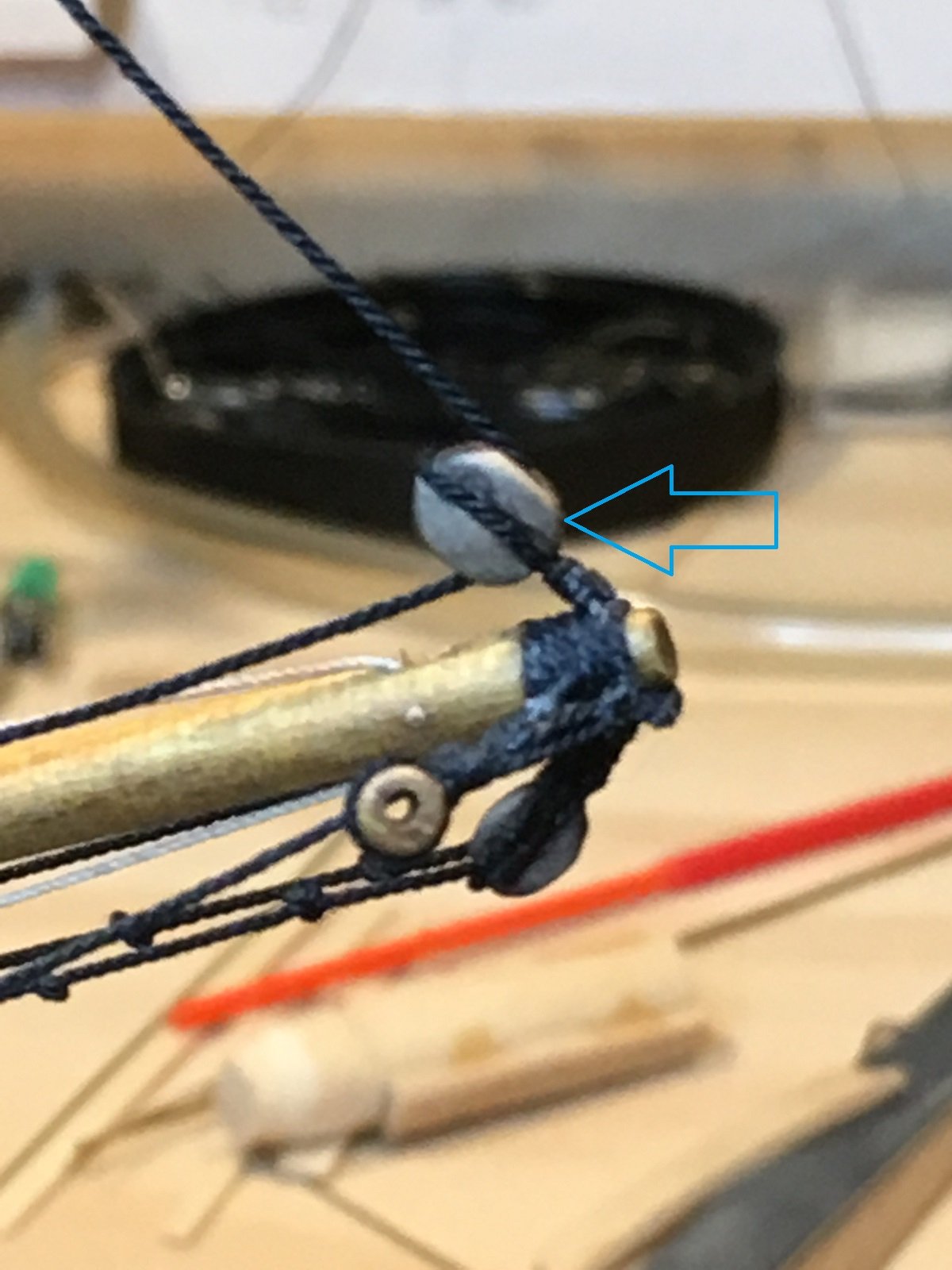
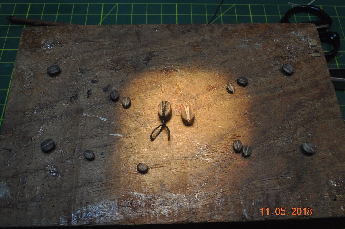
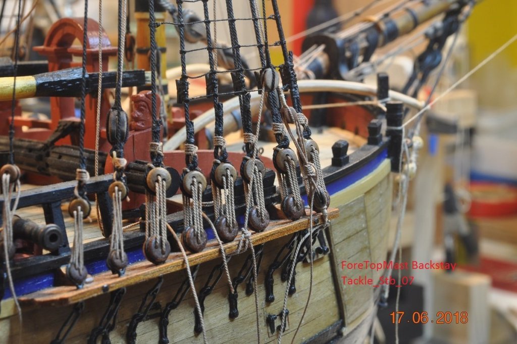
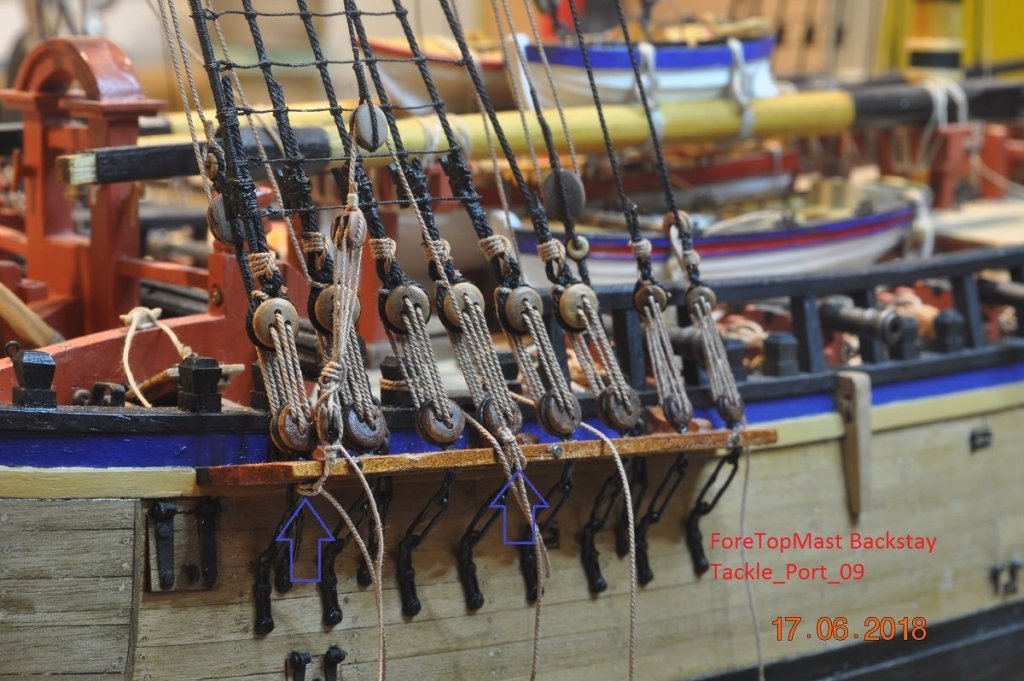
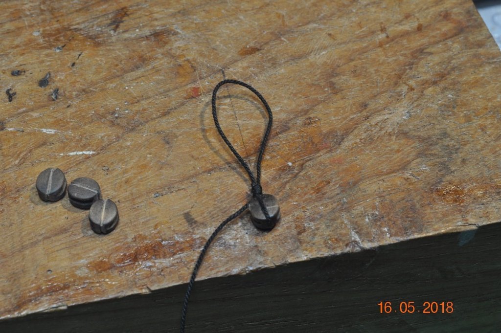
Shipyard Update: The shipyard has been at it again. Some progress that is. We have started the Fore Top Mast Backstay Tackles. Below: Mast Backstay Tackle from AoTS: Above: is the diagram from the AoTS, depicting the bottom of a Mast Backstay > can be tightened via a tackle attached to 2 Dead-eye below the channel. And below the tackle setup for the Starboard ForeMast Backstay Tackle. These Backstays have been hanging about for several months now, waiting to be finished(tackled !!) off. Not sure of the knots to the dead-eye below the channel, used half hitch on the front and bowline on the rear. A couple of pictures of making the blocks. Tackle: I used a Double Block for the top, only as the rope starts from the bottom block up and goes that way twice. Tackle: The lower block I used a single bock with a loop in the rope around a rod to simulate a "thimble" to attach the tackle rope. 3 more to go.

-
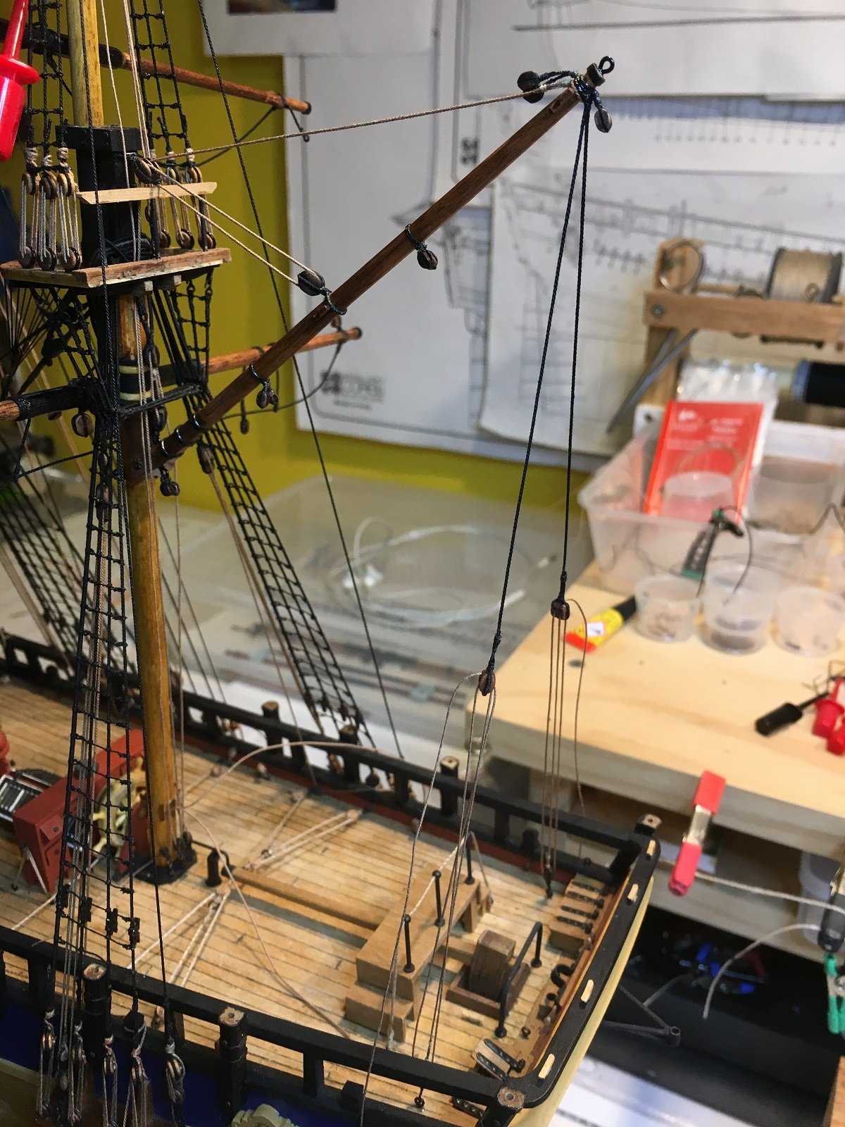
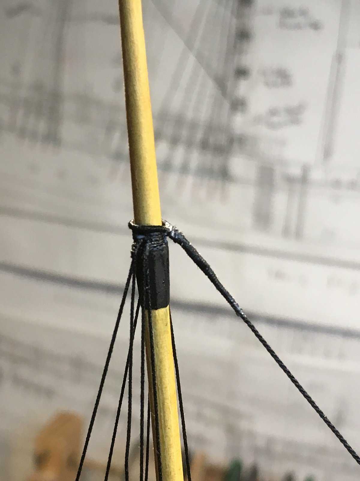
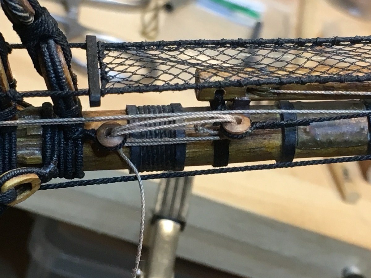
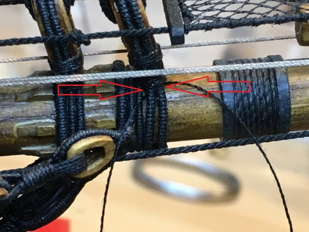
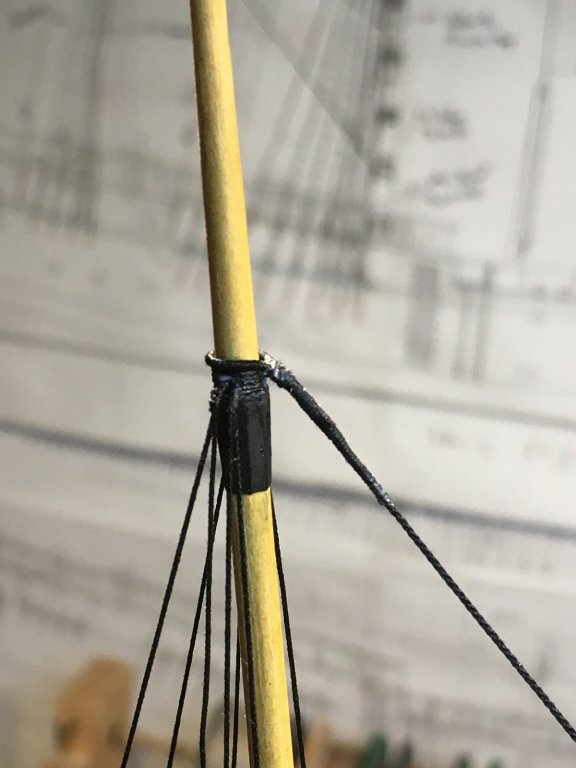
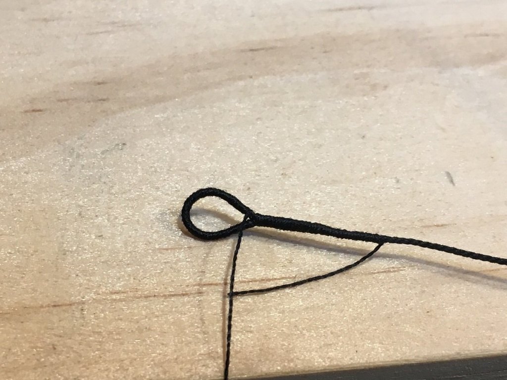
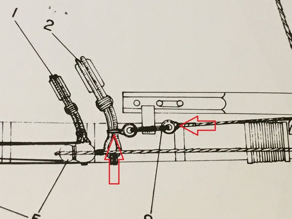
Shipyard Update: The shipyard has been a little busier. We have fitted the Fore Top Gallant Shrouds, but lower ends not tied off yet. Same for the Main Top Gallant Shroud lower ends. Just cannot get into it at the moment so... Fore Top Gallant Stay: I made the Stay off Mast, Top end Loop larger to fit over the Mast Cap Above: Using 0.45mm rope I made the Loop which goes around the TG Mast, above the Shrouds. I leave a length of the wrapping thread to close up the gap to the mast. See below. Above: Stay in place with further wraps of the thread to close the gap to the mast, then 50/50 PVA water over the lot. Above: Stay to the end of the Boom Jib. Above: End is lashed between 2 thimbles as per above, detail from the AoTS. Need to get the left thimble tied around the Fore Stay Boom Lashing. Above: Lashing under & between the red arrows. Above: Which, with a bit of luck managed to sneak a rope under and attached to Thimble. Above: ForeTopGallantMastStay end lashing. Tip: take the stay loop end(top) off the mast and do the thimble end lashing before fitting it all. Lots more to do.


-
Thanks Greg. Feels like it may be a long way off yet. Hoping it will all be dusted by end of this year.
-
Thanks Pat, Trying my best to get the proportions right. Slowly working my way about the Masts, adding the yards etc. in hope of not having to pull something off to add something missed. Cheers
-
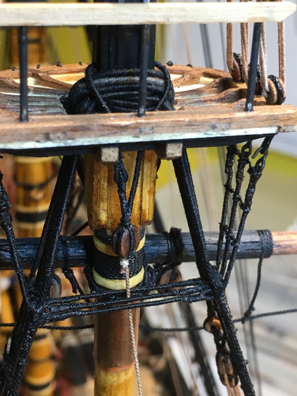
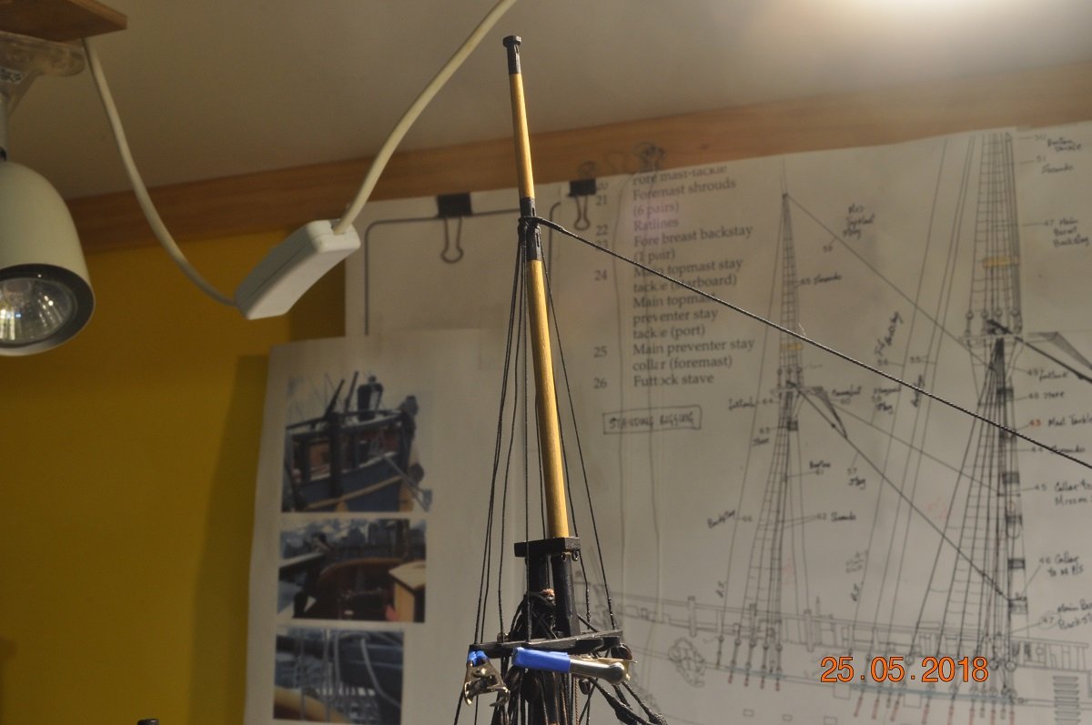
Shipyard Update: The yard has been busy(about time I say), hoisted the Fore Top Mast Yard with Tye blocks and tackle. It's much the same as the Main in the previous post. Next step was to start the Main and Fore Top Gallant masts. Below is the Main Top Gallant mast installed. The shrouds are from 0.3mm rope with the Stay being 0.45mm The shrouds are seized where they go through the tree outer arms, long enough to reach down to the Futtock below. That final tying off yet to be done. Close up of the Shrouds and Stay about the MTG mast. The Main Top Gallant Stay runs forward through a rear block lashed to the Fore mast Top Mast head. Getting mighty crowded around the mast top. The stay runs down and is lashed to the Main Mast Stay loop about the Fore Mast. Somehow I need to get a lashing above the 2 hitches. !! Next is to attach the Fore Top Gallant - similar but with Stay going to the outer block of the Jib Boom.


-
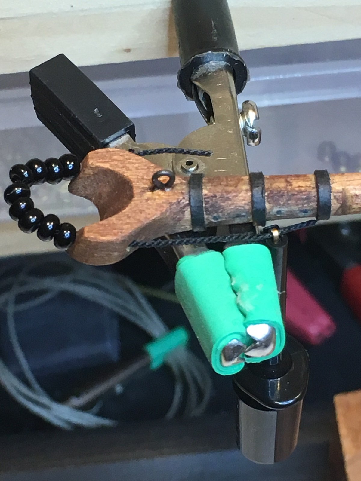
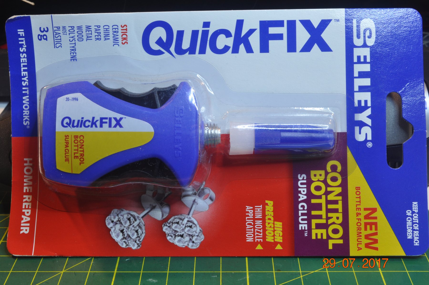
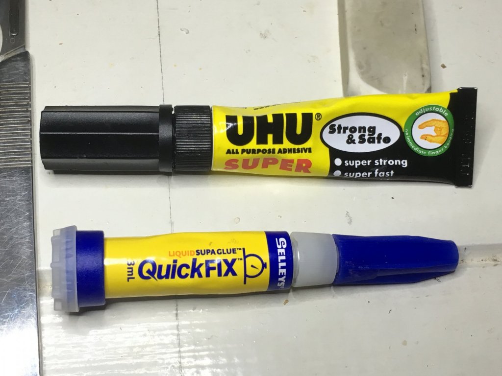
My 2 bits worth. Nothing beats tying the knots properly. A dab of CA to stiffen the rope end or keep in place. I used to use these 2 types below - here in Aussie.. However they clogged up as the glue stays in the nozzle. The UHU (superstrong super fast ?) seemed to not dry as quick as the QuickFix did. HOWEVER Then found this Selleys QuickFIX dispenser. It controls the amount of CA glue coming out by the "black" squeeze handles on the sides. When you let go of the handles, the glue "sucks" back up the nozzle a bit. The instructions say to "tap" the bottle down on it's base to help the glue go back inside. I use the pointy end of a long pin to dab a small amount onto the spot. It works. But the best I find is to wipe the nozzle end, every time I use it. I get full use out of the bottle and nozzle this way, If too much is on the spot/rope, I wipe the excess quickly with tissue or tip of finger so I don't get a "shinny" finish. But, I agree with MTaylor, 50/50 white PVA/Water mix over the rope, soaks in to seal the lot.

-
Keep going Steve, Great additions to the gal.
-
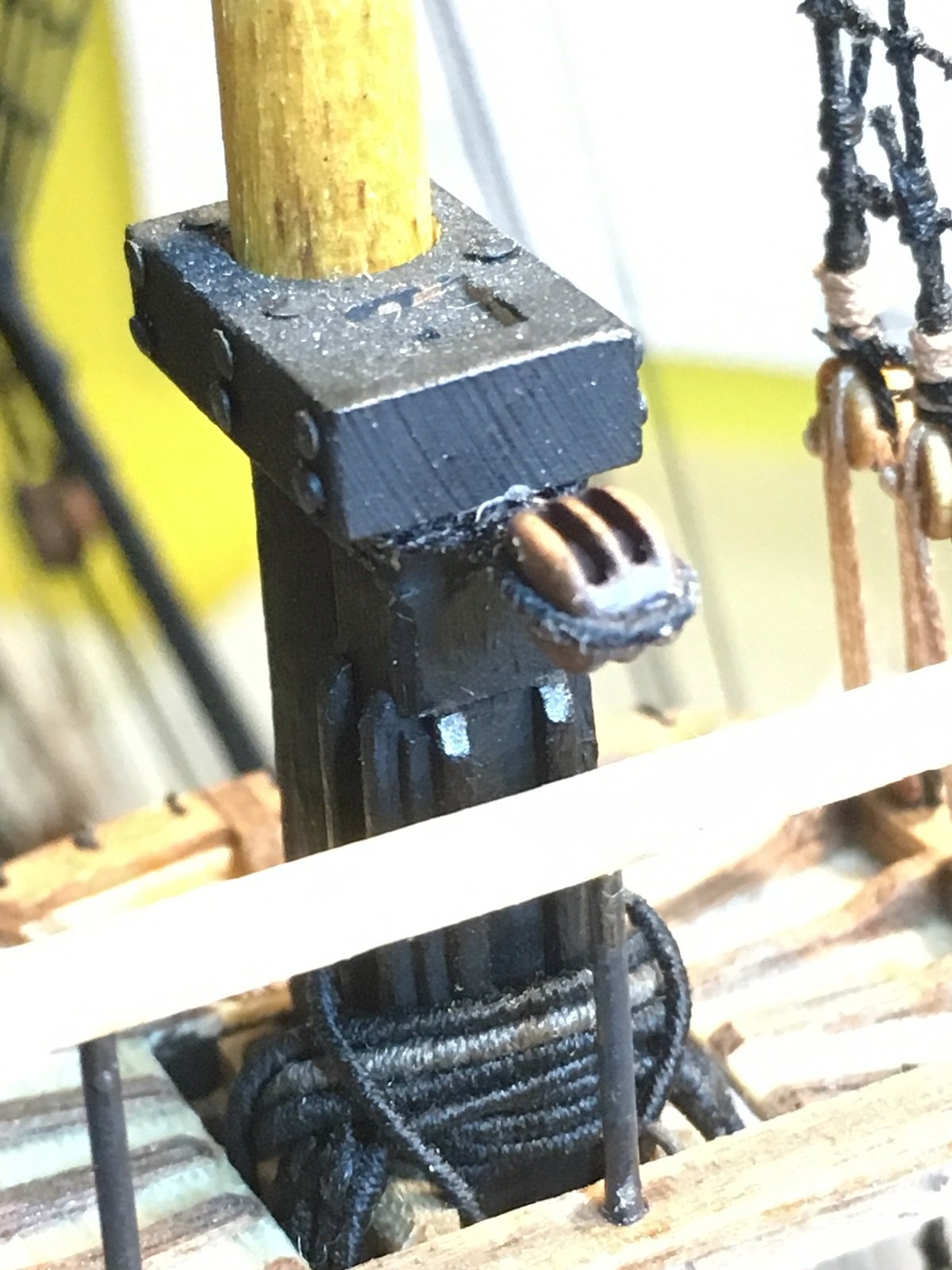
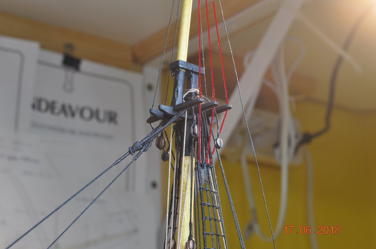
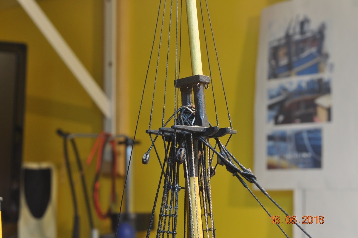
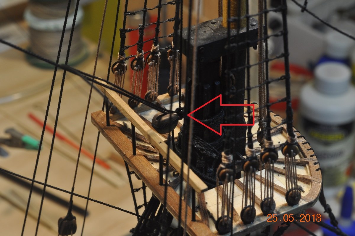
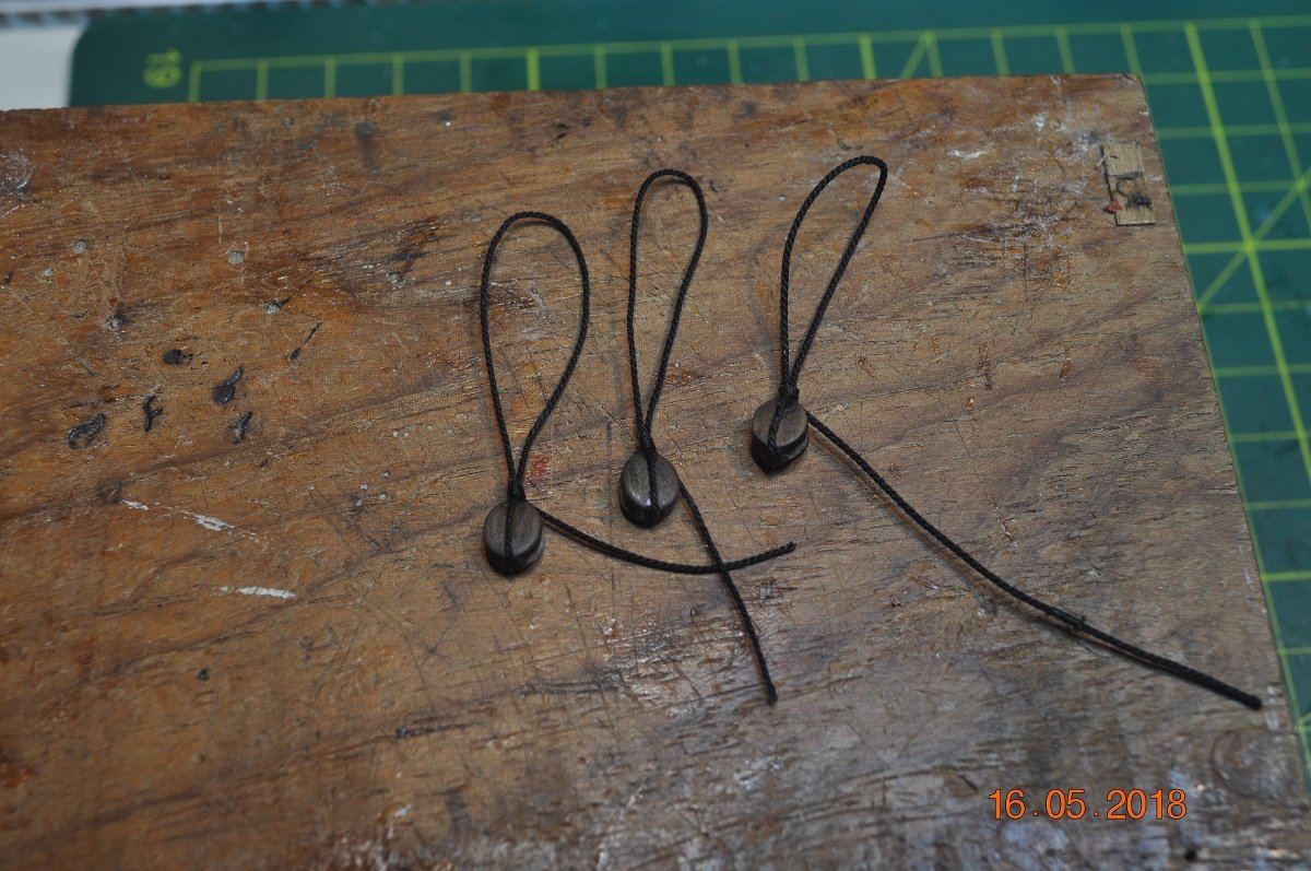
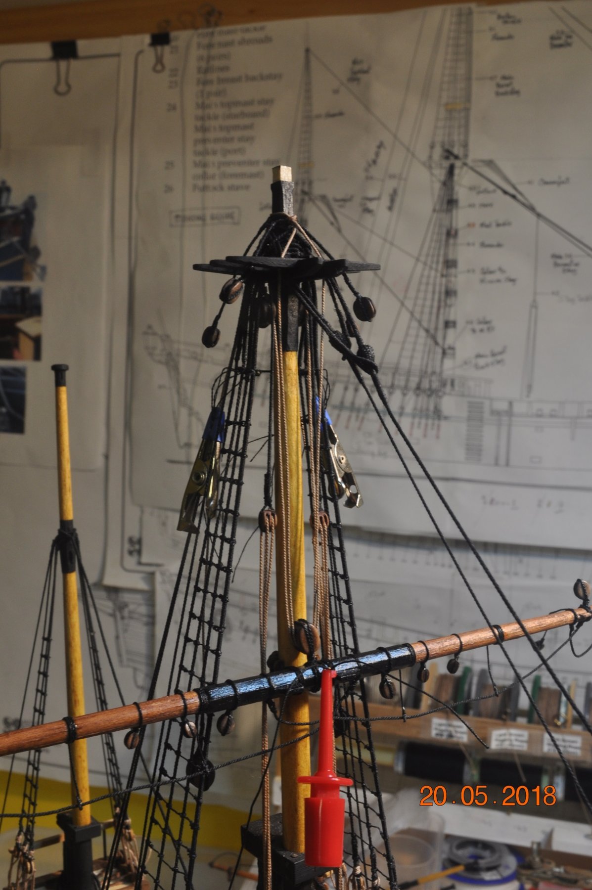
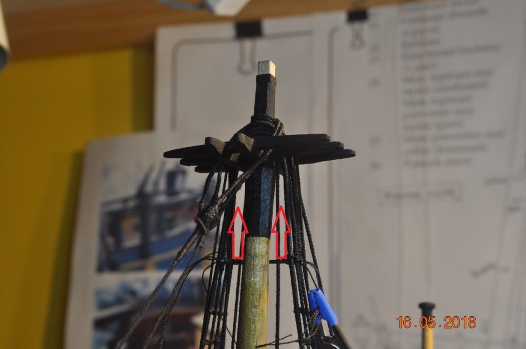
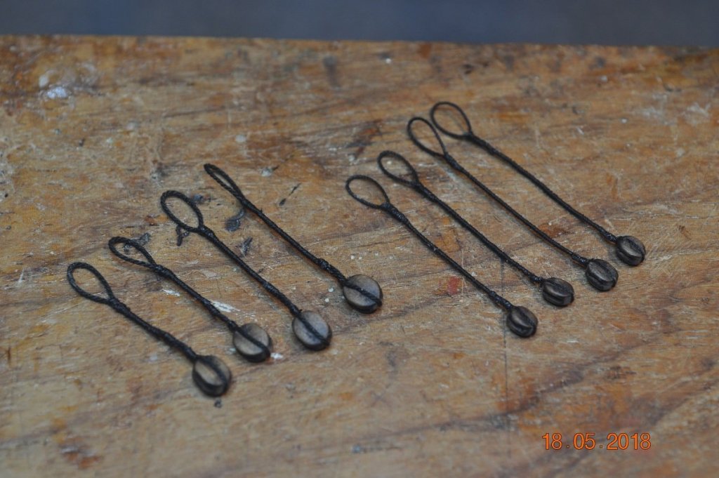
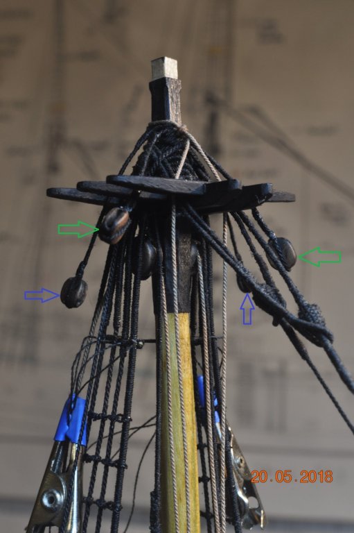
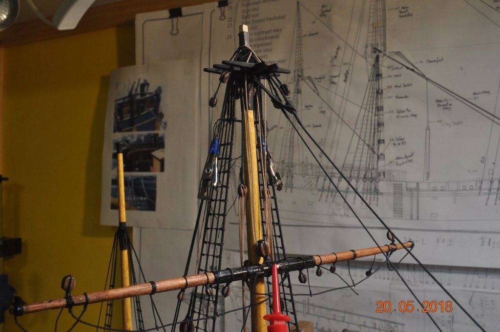
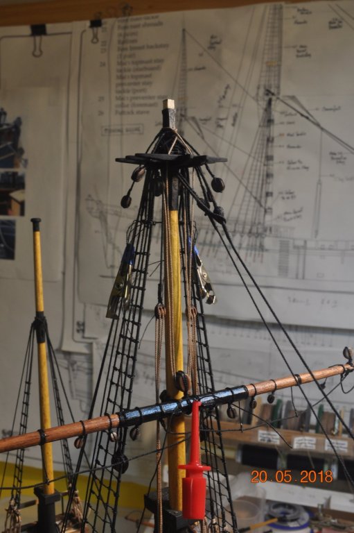
Shipyard Update: We have moved onto the Topsail Yards Tye and Reef Tackle and Lift Blocks. I decided to do these now before I get to fit and stay the Top Gallants. Getting the Blocks ready: The Single Masthead Tye Blocks fit up in the space under the trees. Red arrows point to where the Single Tye blocks are to go. Not much space up in there. The Single Tye blocks being made. I've used 6mm singles as the 7mm (scaled size) were just little bit too thick across the cheeks to fit up in the space. Other 3 completed. Now I made these with 1 pull thread, so when in place simply pull on the 1 thread to lift up under the shrouds/trees. Single Tye Blocks in place. This is a shot at the Main, Fore similar. The Burton Pendant is very close and will have to keep an eye that it stays to the side when fitting the Tye Lifts. Next I made the Long Stropped Lift & Reef Tackle Blocks These need to be made now as the loop end of the strop pairs go under the Tye Lift. Each made the same way as in Pic above. 2 sets of each per Main & Fore completed. The Long Stropped lift blocks (Green Arrow) are looped about the mast head as are the Long Stropped Reef Tackle Blocks(Blue Arrow). The lighter color over the top being the Tye Lift. An keen eye may see that the Lift Tackle about the masthead splays outside the 2 main beams of the cross tree. I suspect it should drop more vertical behind the bottom of the TopGallant. But their is no space for this when the TopGallant is fitted. Next was to fit the Yard Tye Block Lift Tackle Trial fit of the Lift Tackle. Parrel fitted around the Mast (Red Arrow). They run up/down very well. Tye Tackle upper Double Blocks (Purple Arrow) Next will be to do the Fore Mast then run the Tye Tackle down to the eye on the channels. All above items in place. Getting close after all these Topsail Yards and Tye Blocks/Lifts to fit and shroud to Top Gallants.


-
Hi Barbara (and Dad), I am in awe that you have taken time to spend with your father to work on the "Victory" together. He has created a wonderful model, a credit to his earlier years and now to continue with your guiding assistance, and now all hands on deck.
-
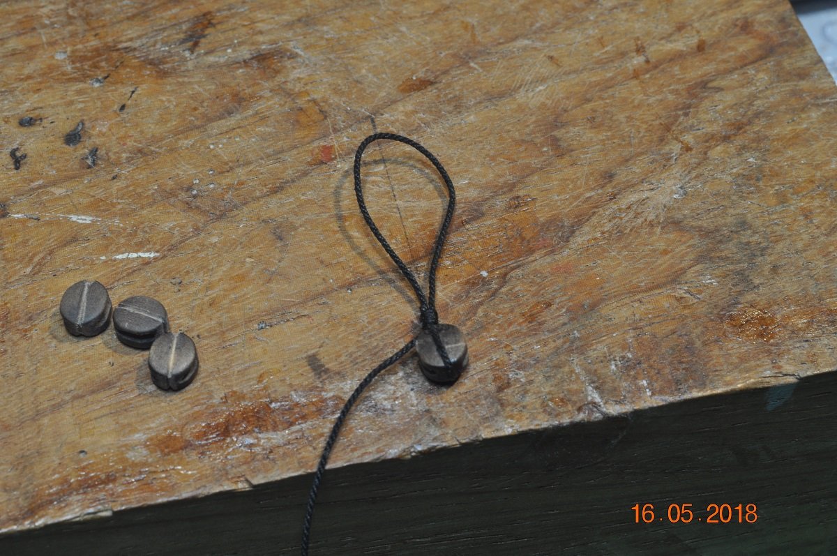
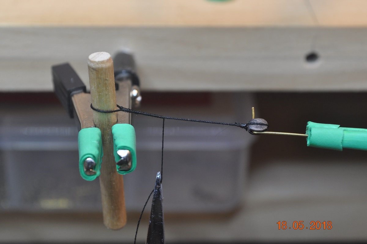
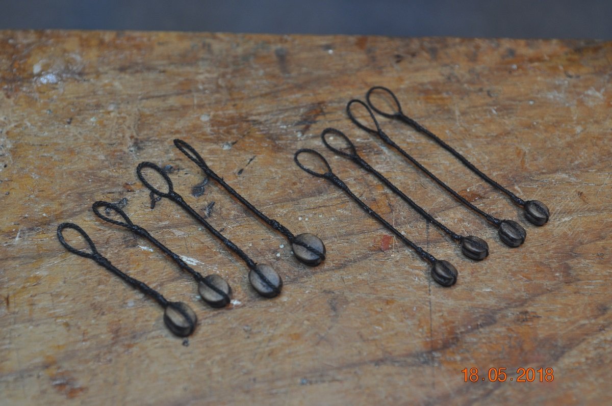
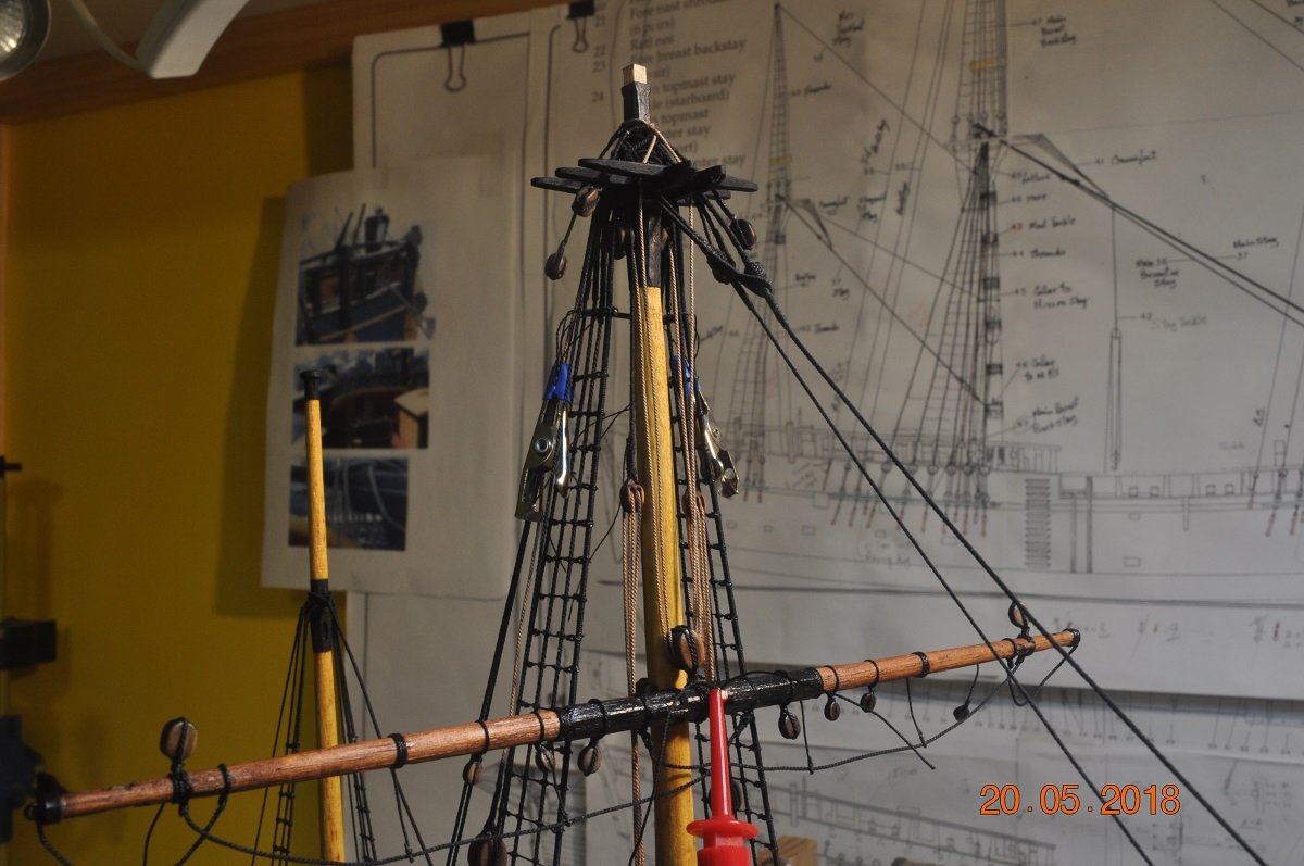
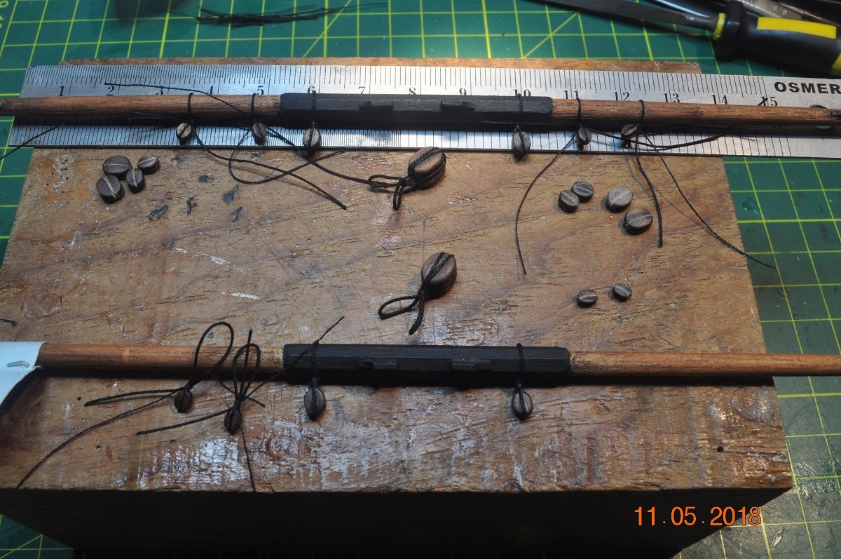
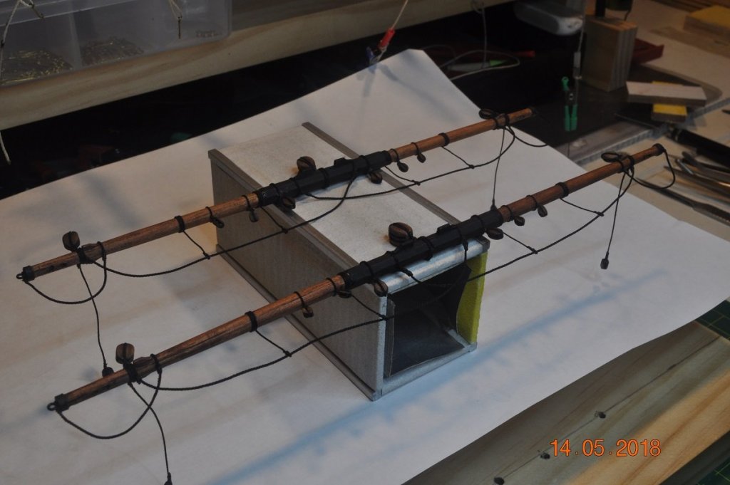
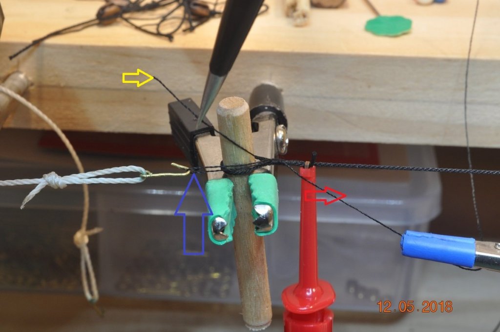
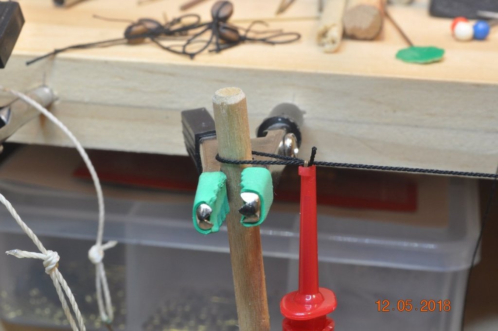
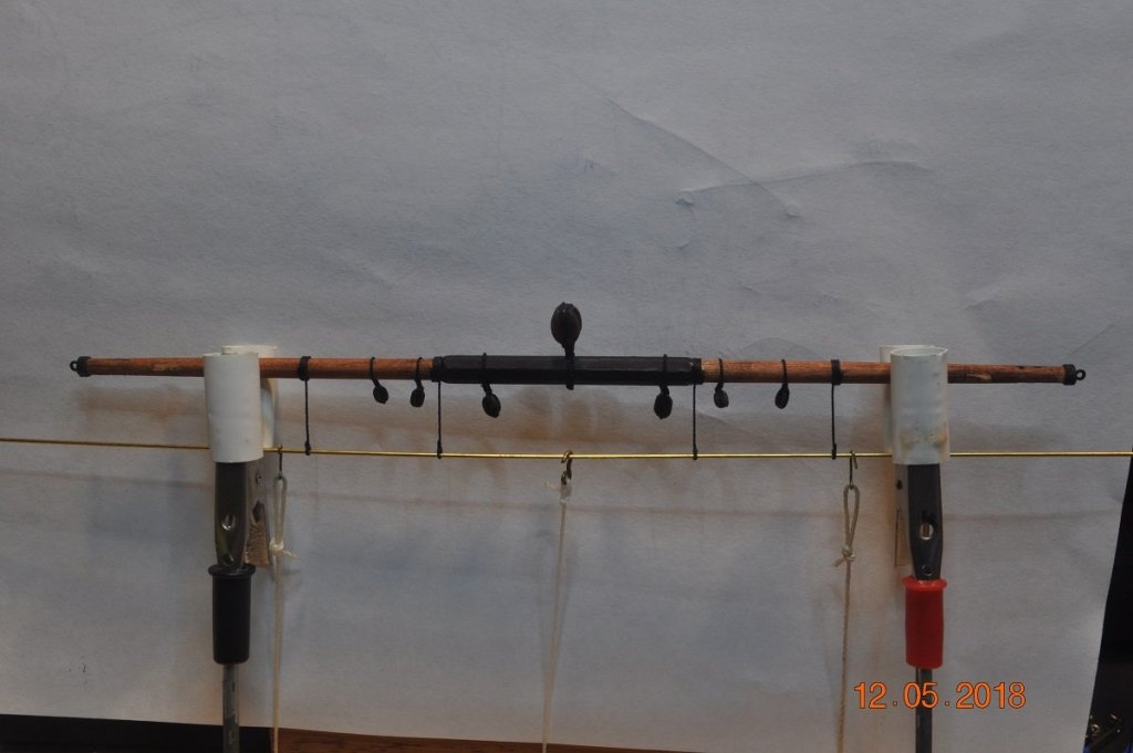
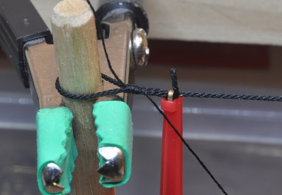
Shipyard Update: The slackers in the yard have been a little busy fitting the Blocks & Ropework on the Main & Fore TopSail Yards. Getting the Blocks ready: I find it easy to make all the items of similar items at the same time, so when it comes to putting it all together, can do more than 1 and speeds things up. Plus maintain consistency. Above: Each sized block I groove the sides and ends for the rope to go around. Above: Progress with the Jeers ready to be attached, some others already on etc. Matter of progressively working Above: Little jig to hold the yard whilst setting up the Horse Stirrups. Set them with 50/50 PVA/water mix to hold in place. Below is a short set of 3 pictures showing how I make the rope loops, to attach to the yards (or other situations) Above: I use a peg of similar size to the spar, loop the rope about and hold with enough space to seize with twine. Above: I have a number of hooks and clips to hold the main rope, also to hold the seize twine. See if I can describe the process. I start with the twine held by the blue clamp on the right. The twine passes to the left through the left hook (blue arrow) and back to the right. (the twine loop through the hook is used later to pull the final wrap into the seized section) Just before the red clamp I start wrapping the twine around the 2 lines back towards the "peg", wrapping/seizing the required number (3 or 4). This can be hard at first, but with pointy nose tweezers you can hold the twine in place and start the wrapping. The wraps might not go all the way to the peg. That can be fixed later. You hold the the final wrap/seize (I put pressure with a finger), loosen and unhook the hook from the loop. Then thread the twine through the "hook loop". Whilst holding the twine end (yellow arrow), pull the right side/end of the twine, in direction of the "red arrow". This pulls the loop towards the seized section, and pull the twine on the right side till the loop is gone, and the left twine end goes under the seized section a bit. Above: Hopefully you end up with something like this. I usually can slide the seized section alone the main ropes when attaching to the yard or other item. Glue in place and trim the unwanted ends. Above: Here is a Horse loop in place on the yard. Above: The 2 Top Sail Yards completed.


-
HMCSS Victoria 1855 by BANYAN - 1:72
DaveRow replied to BANYAN's topic in - Build logs for subjects built 1851 - 1900
I'm back in Model Mode. Those added details look really good Pat. The funnel come up great. Hardly tell how it was made.- 993 replies
-
- 4
-
-
- gun dispatch vessel
- victoria
- (and 2 more)
-
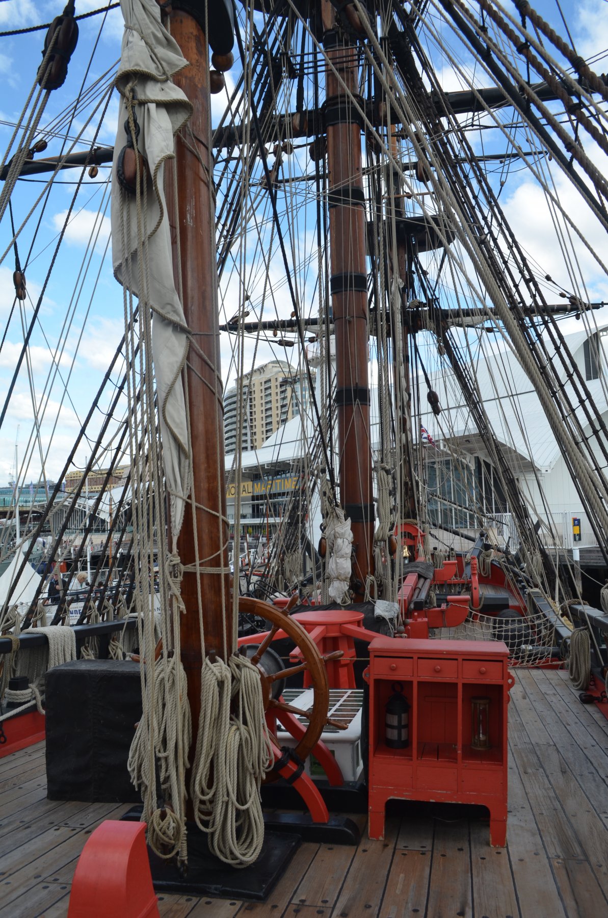
Great progress there Rod. The Australian Replica of the Endeavour has had some modern "Safety" features/adjustments incorporated. Their are "vents" on the deck where pumps were fitted. A Diesel Engine was installed. The Binnacles to either side of the steering wheel, appear to house the diesel motor instrumentation, the compass etc. I as you have found out, very tight "fit" for all the items between the Main and Mizzen Masts. This picture shows a "on shore" binnacle for visitors to to imagine what may of really been on deck. Pic compliments Greg Shard, Endeavour at Darlington Harbour, Sydney at the Maritime Museum.

- 108 replies
-
- 3
-
-
- endeavour
- caldercraft
- (and 1 more)
-
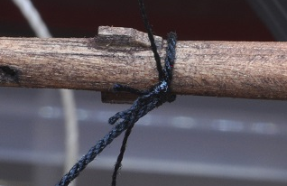
Shipyard Update: You may say "I'm Back" Well it looks like a full month my shipyard has been on an extended break. With the Commonweath Games, then catching up with some paid work, time got away. Mizzen Crossjack: I just had to add something to the model. I had made the 2 Main & Fore Lower Yards and the Mizzen Crossjack a month ago. Time to get things onto the model and finish her off. Above: Mizzen Crossjack in place, the Sling for the Yard Sling Block highlighted. Tying knots in-situ, is a challenge in itself. Many more to come is the reality. Above: Crossjack, other (Port) side. Above: Crossjack stern view, Parrel Sling for the Crossjack. Sling and block details >> page 105 of the AoTS.