HOLIDAY DONATION DRIVE - SUPPORT MSW - DO YOUR PART TO KEEP THIS GREAT FORUM GOING! (Only 36 donations so far out of 49,000 members - C'mon guys!)
×

captain_hook
-
Posts
685 -
Joined
-
Last visited
Content Type
Profiles
Forums
Gallery
Events
Everything posted by captain_hook
-
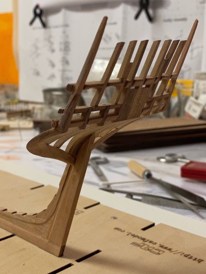
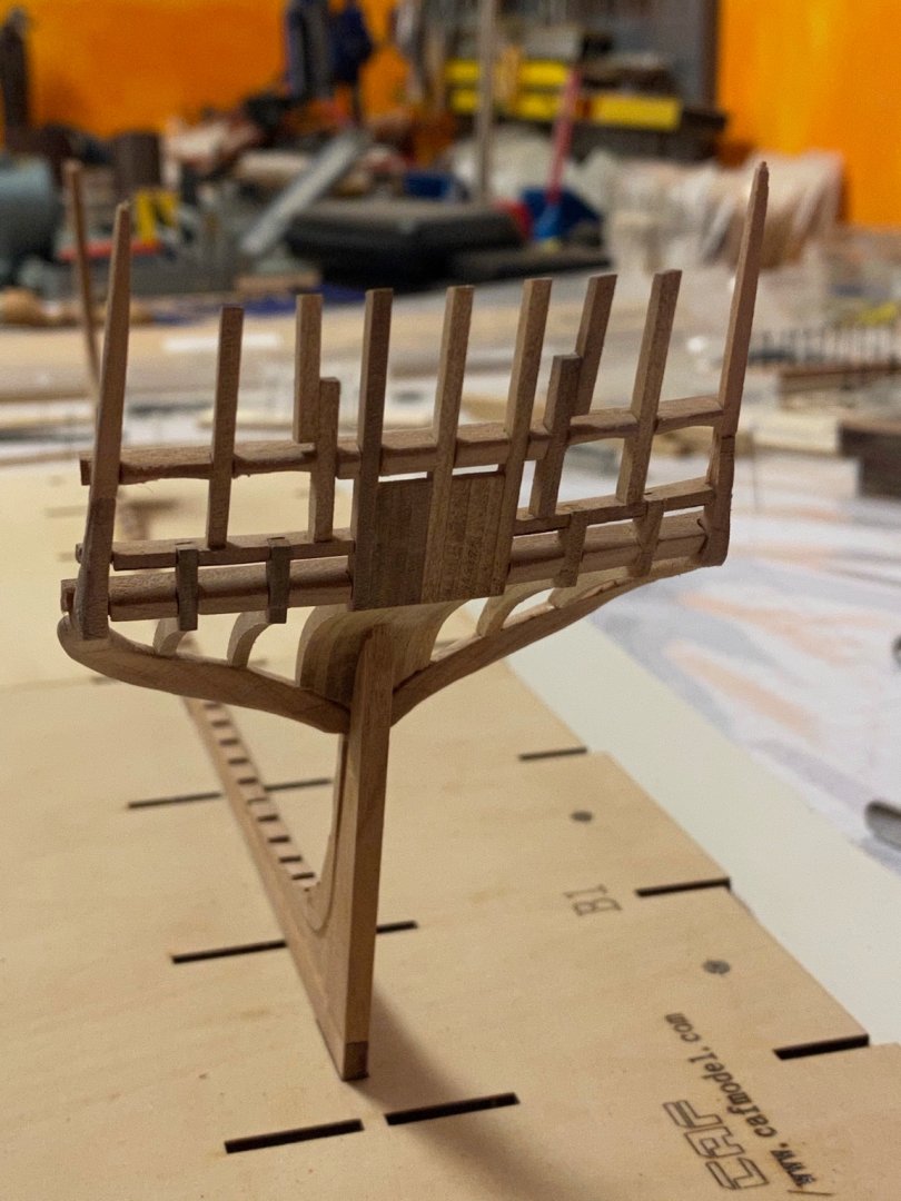
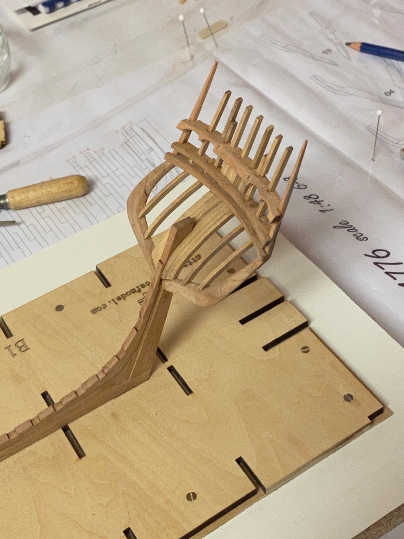
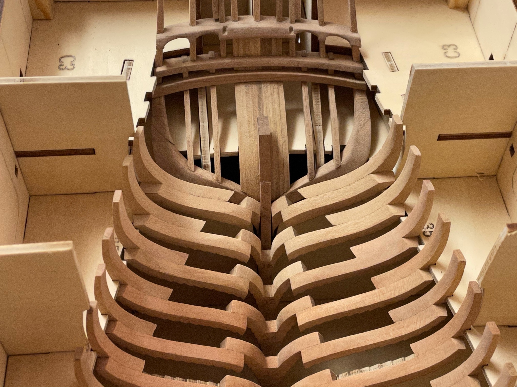
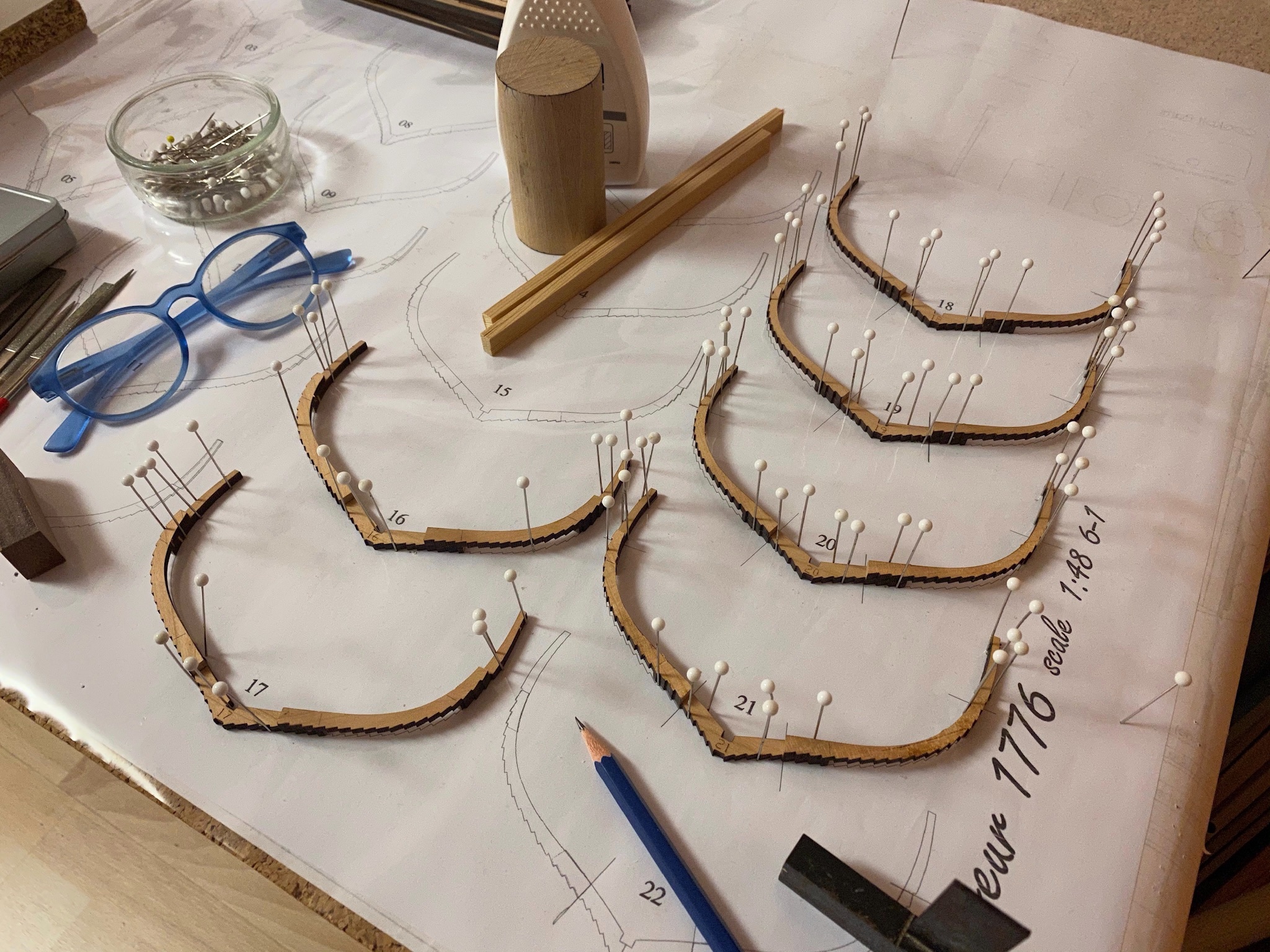
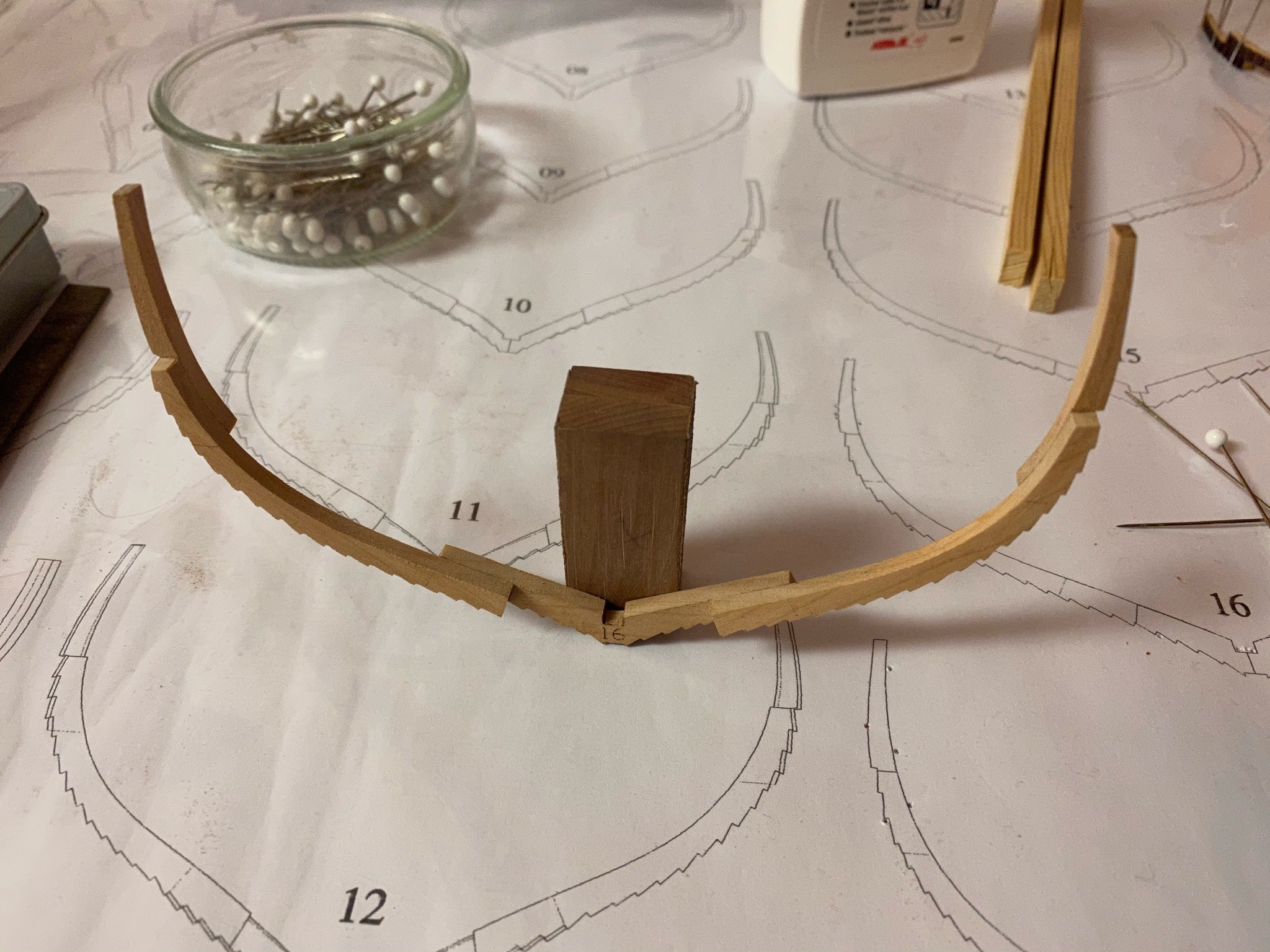
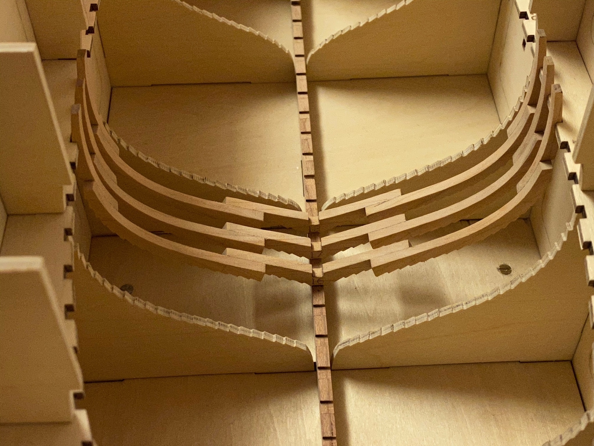
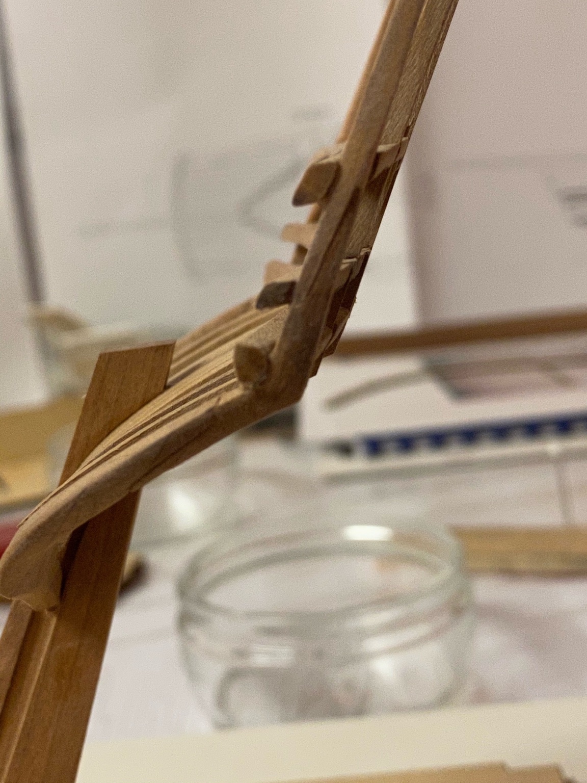
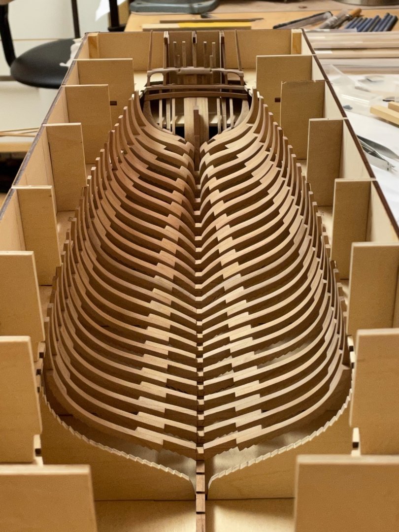
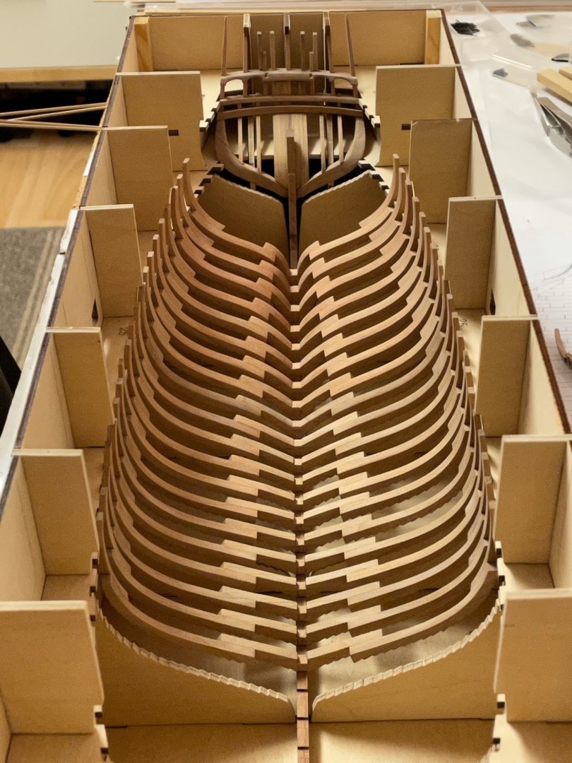
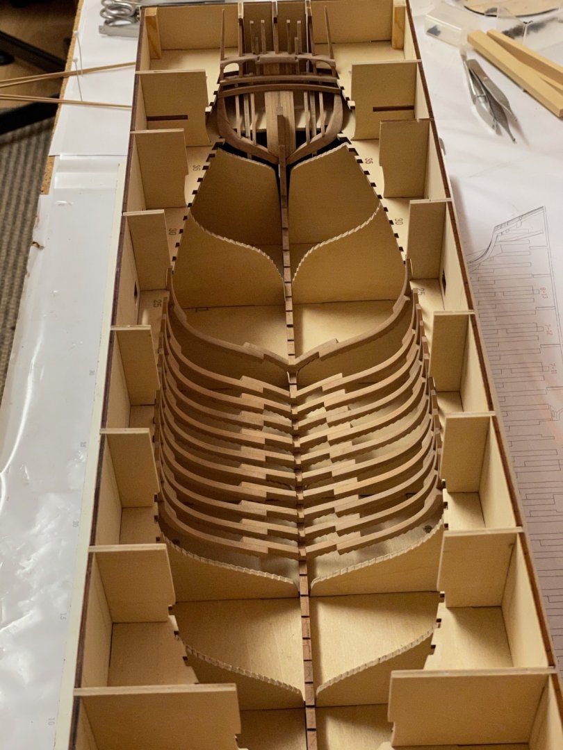
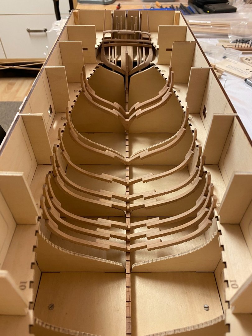
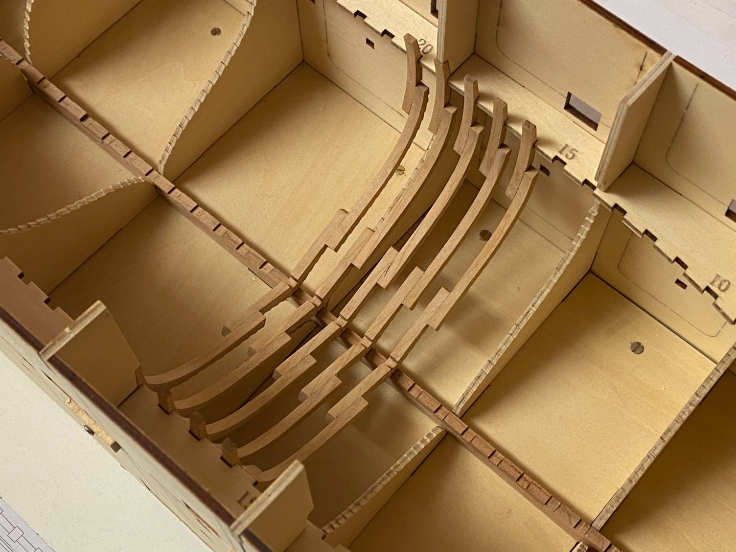
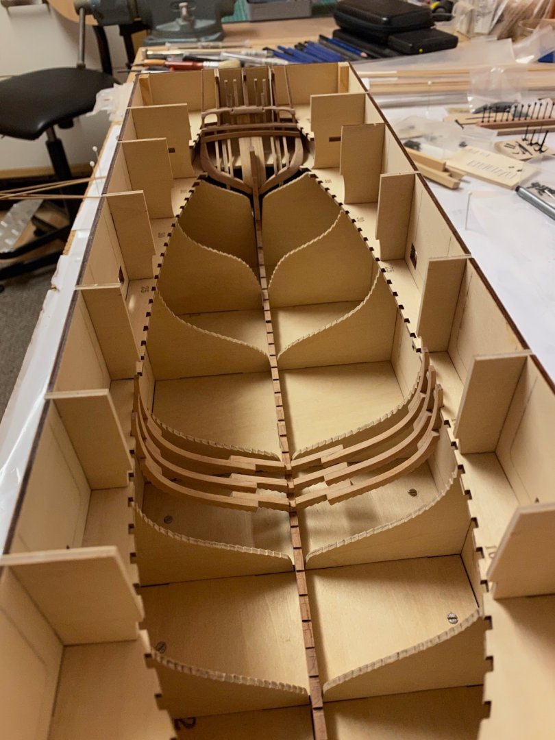
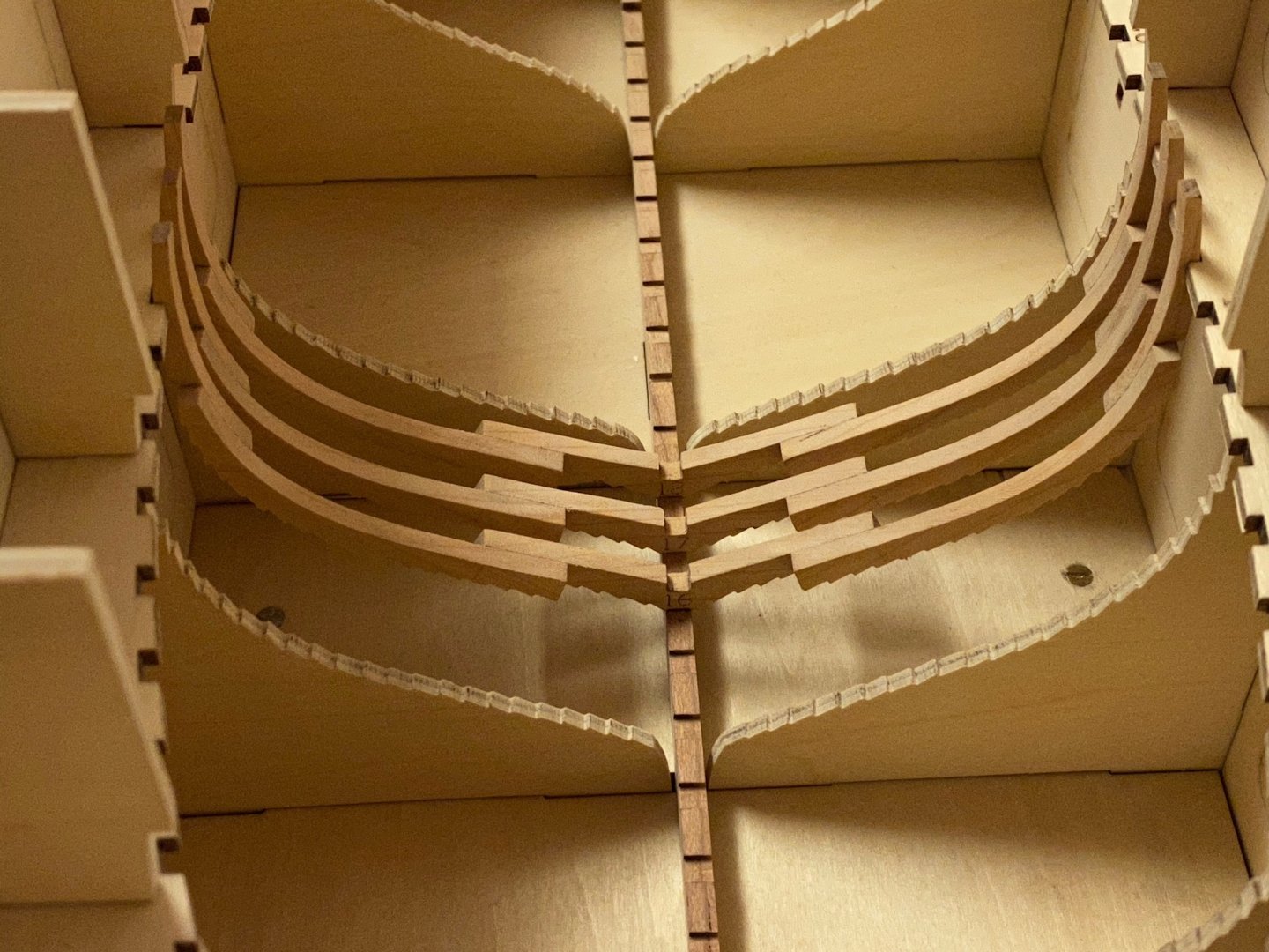
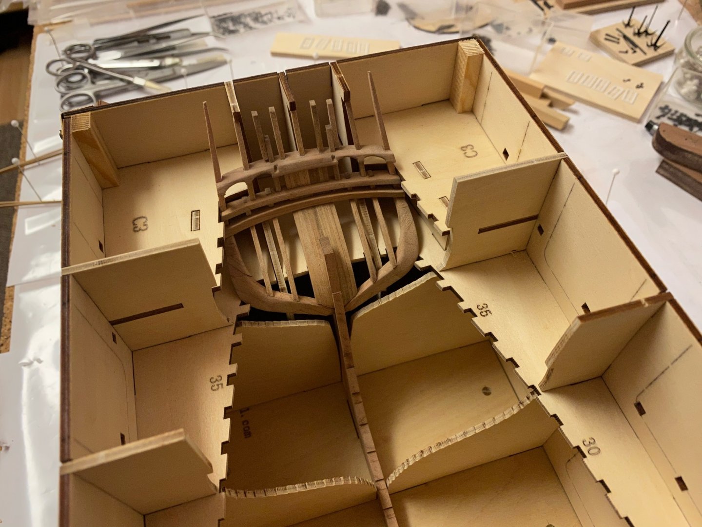
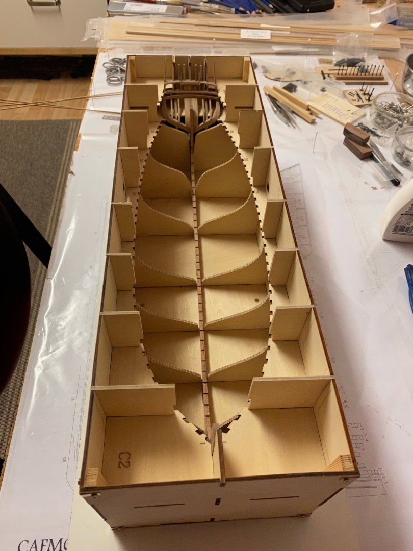
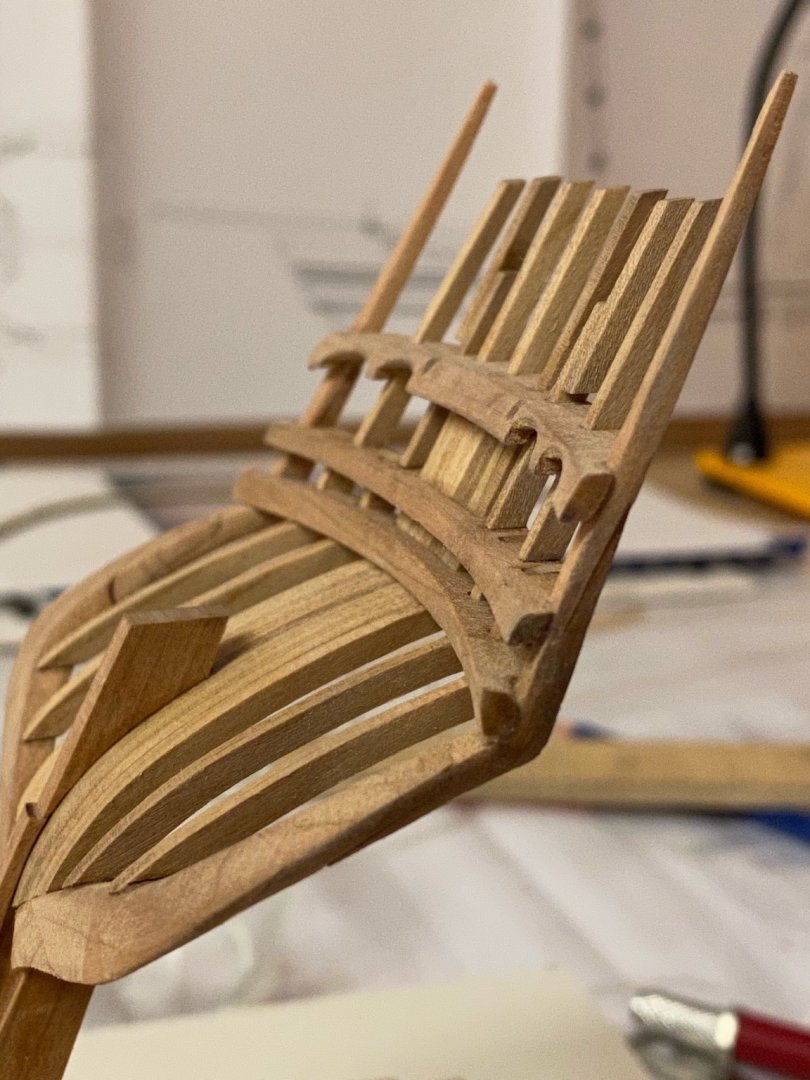
 Thank you very much James and Bob, While processing I‘ve finally reached the stern. The last three full ribs needed a lot of tapering. I find it more easy to assemble the middle and upper segments first using the engraved guide lines. Then I fix the lower futtock on the plan with pins. The pre-assembled segments are then attached using the plan as reference. So you only have to deal with three instead of five segments. The last three frames 38 to 40 are just single segments (upper futtocks) and I will add them later in the build. I will continue with the ones at the bow next weekend. The jig has to be modified a little because some side parts interfere with the frames that are supposed to sit on top of them.That is why the corresponding frames on the pictures don‘t sit down as tight as the other ones. This time the upper futtock‘s lower edge form a closed curve as per plan. Still a lot of work to do. Stay tuned and save.. Andreas
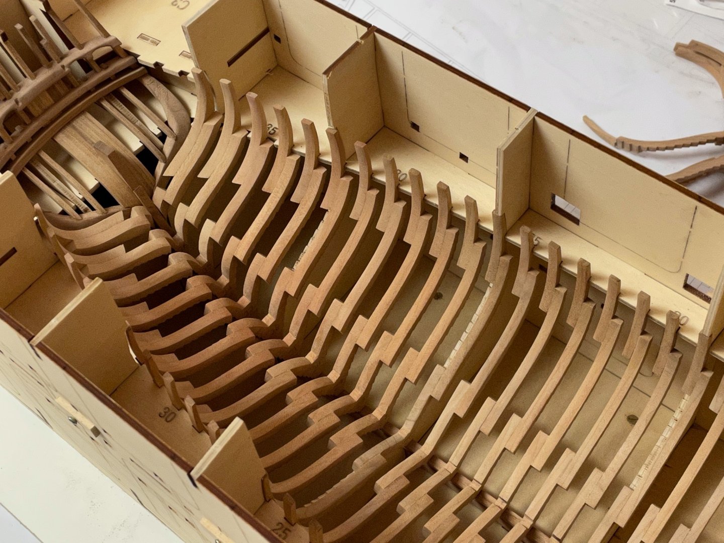

-
Very nice!
-
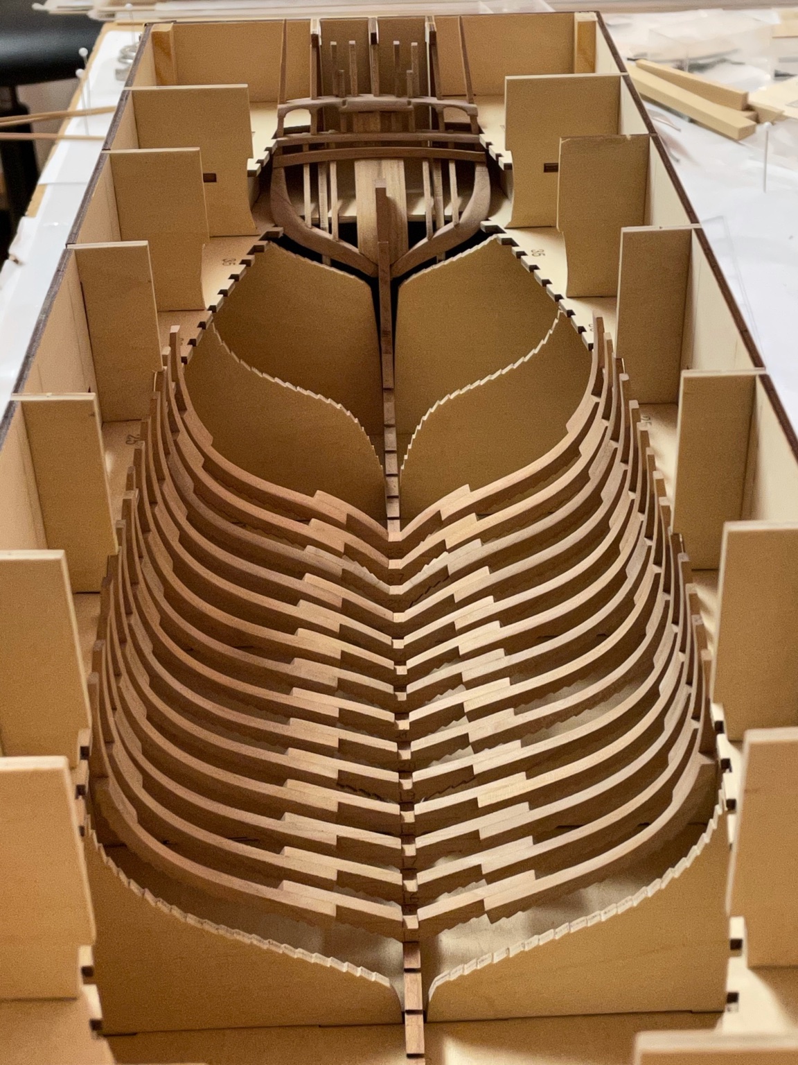
Still assembling frames, lots of repetitive work. But I’m approaching the stern...
-
Thank you very much, Jeff. More frames have been prepared. As I make my way towards stern I finally found out what went wrong last time with the tapering. The rear markings for tapering on the upper futtocks are sometimes misplaced - means that you have to check the plan instead of the markings. I used my disc sander to carefully sand a little and compared the tapering with the plan until the correct angle was achieved. This has to be done with all upper futtocks as far as I can see .. Continuing next weekend. Stay tuned and save.

-
Preparing more rips towards the stern. This time I won‘t taper the upper futtocks too much and double check the plan. If needed I will taper them later by hand after installation.
-
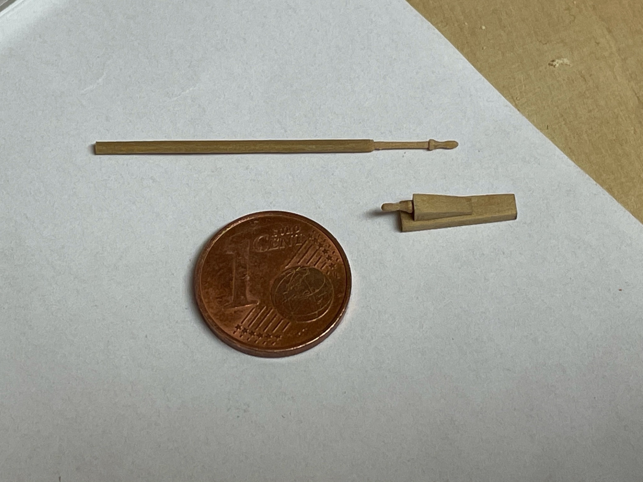
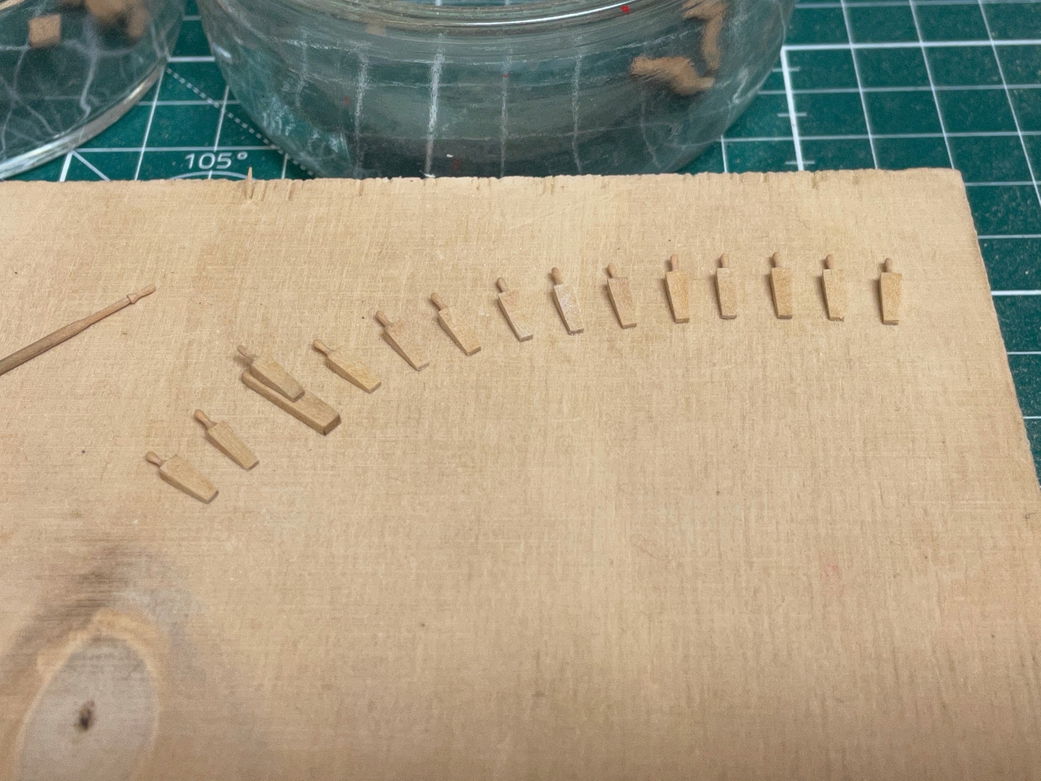
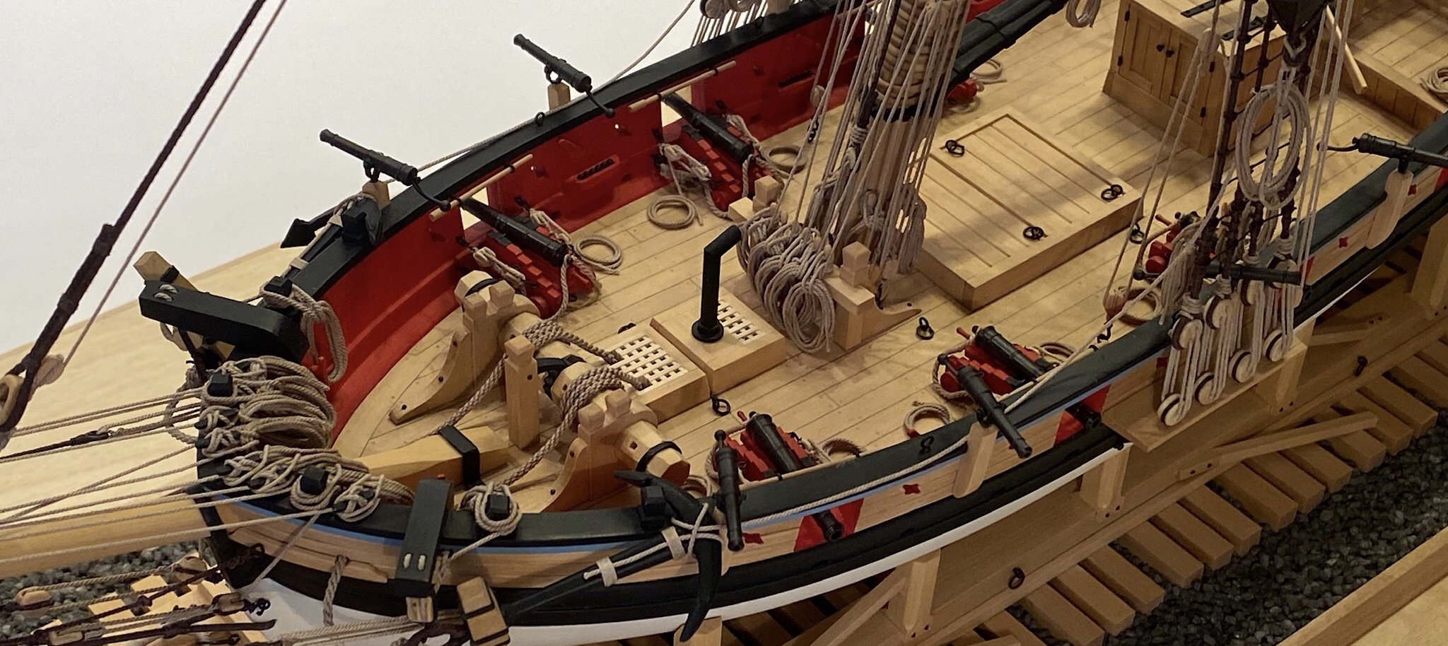
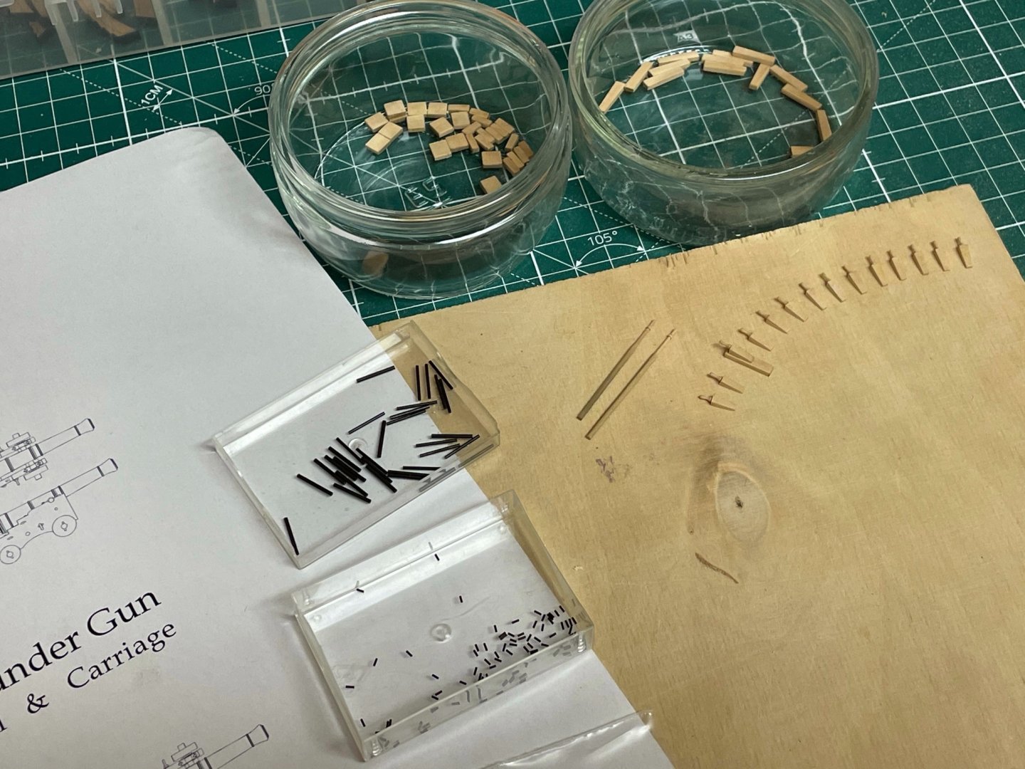
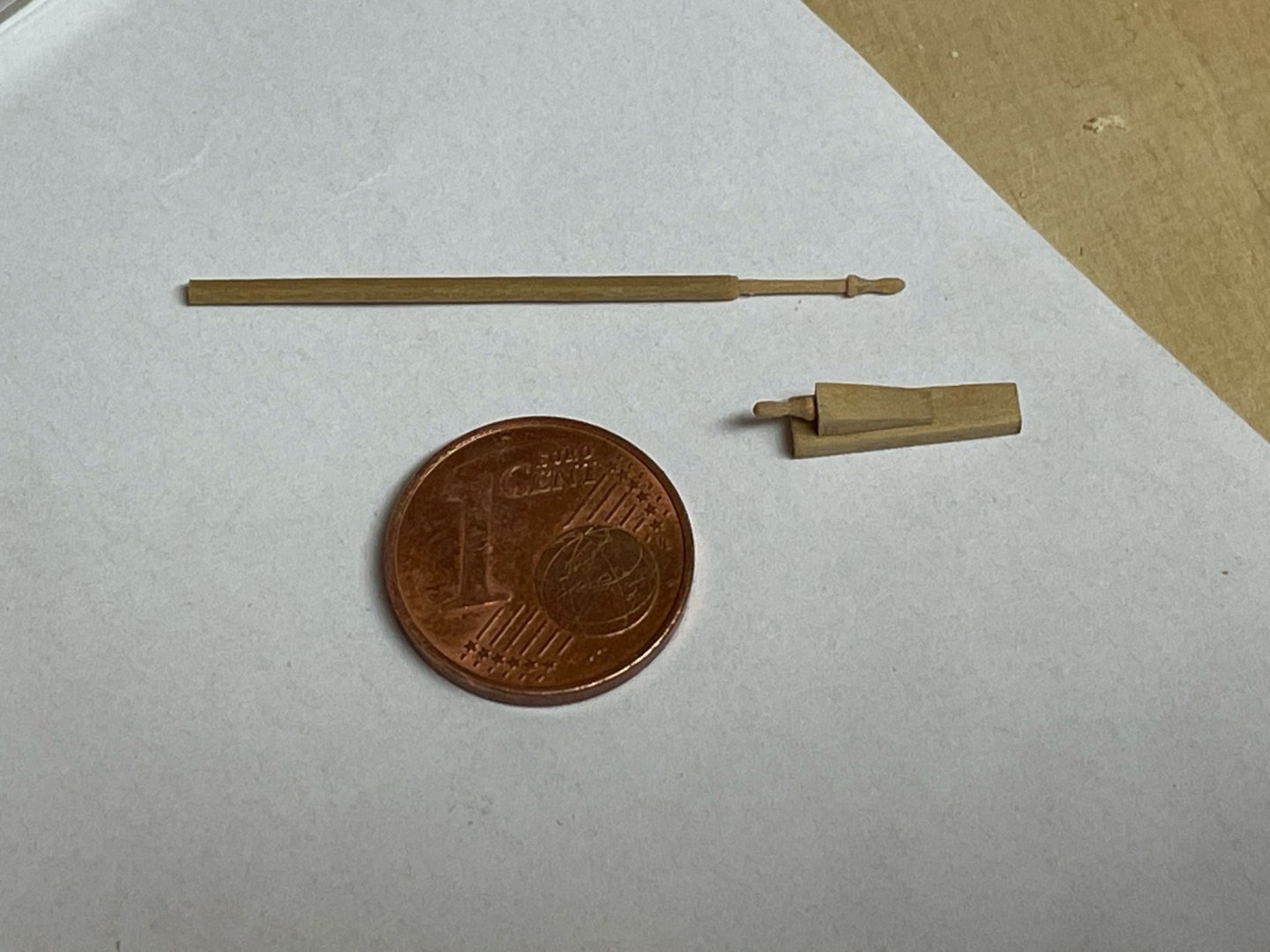
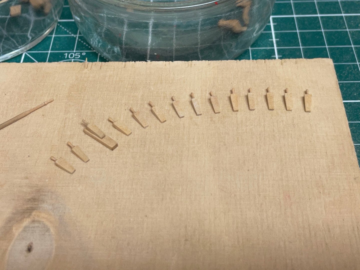
As I had to wait some weeks for replacement parts I started a little side project - the 4-pounder guns. The Badger has twelve of them. For the carriage I use the gun schematic from Syren as reference, enlarged to fit the 4-pounder barrels. The handle of the quoin was made of 1,3mm boxwood dowel and turned to shape with a needle file. Still have to make the axles, the side parts and the wheels. Stay tuned...
- 64 replies
-
- 11
-

-
- badger
- caldercraft
- (and 1 more)
-
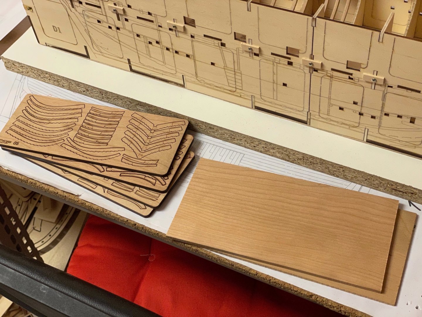
Due to the pandemic the replacement parts took about 3 weeks to arrive here. But now I‘m ready to continue the build next weekend. Tom also has gently supplied a blank cherry sheet so I can make replacements myself if needed in the future.
-
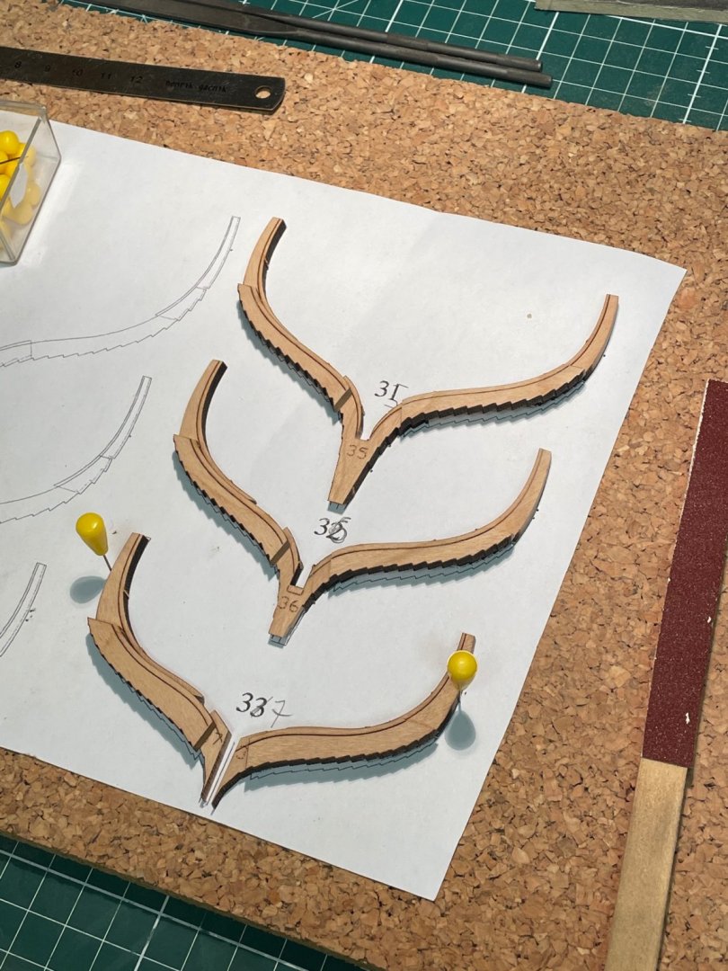
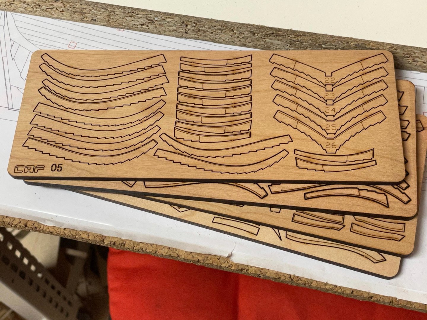
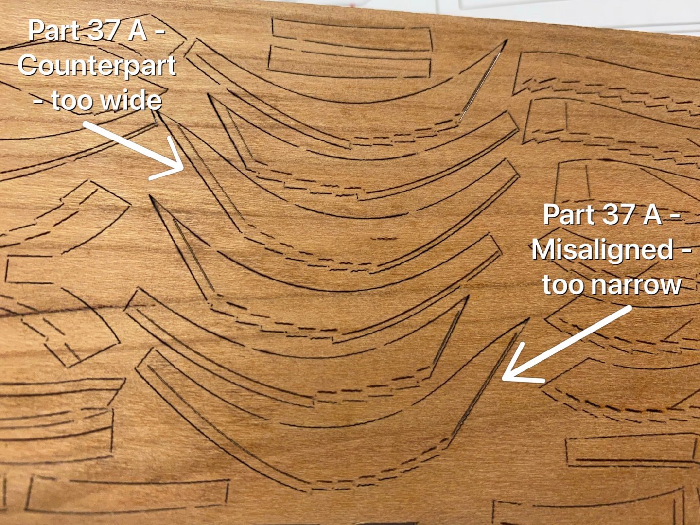
I wish I could say that - but they are not. Take a look at the photo I made from sheet no. 8: Shown are the top futtocks of frame 35, 36 and 36. you can see the tapering lines for the lower heads. The marks on one side are too narrow while the counterparts have their marks too wide. The true line is among between both marks. I have checked the frames 31 - 34 and the tapering is off the plan. I may ask Tom for some replacement sheets and will keep that in mind next time.
-
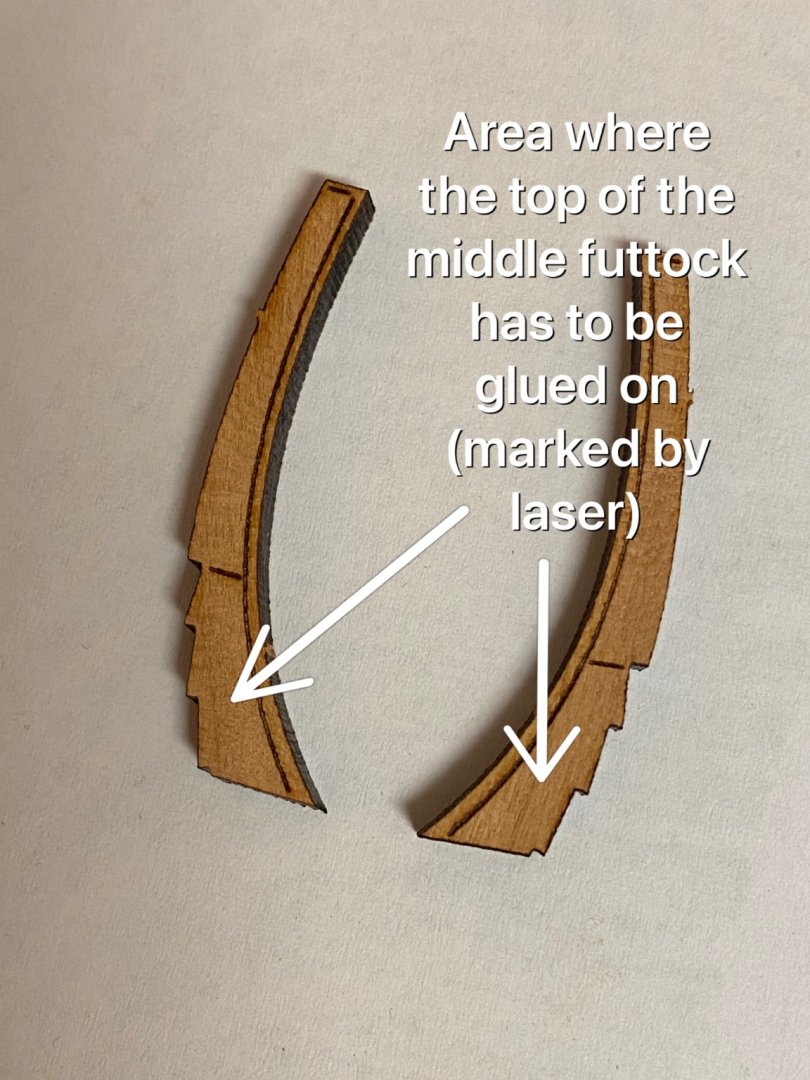
Thank you PetaV for your suggestion. That was my first idea, but the location of every part is determined by the engraved laser markings. For example the area where the middle futtock has to be glued to the top one (and vice versa) is marked by laser. So that part of the construction is idiot-proof (well unfortunately I have proved I‘m not). I rather believe, that the tapering marks do not correspond to the plan and therefore too much substance was sanded off. But I‘m not sure.
-
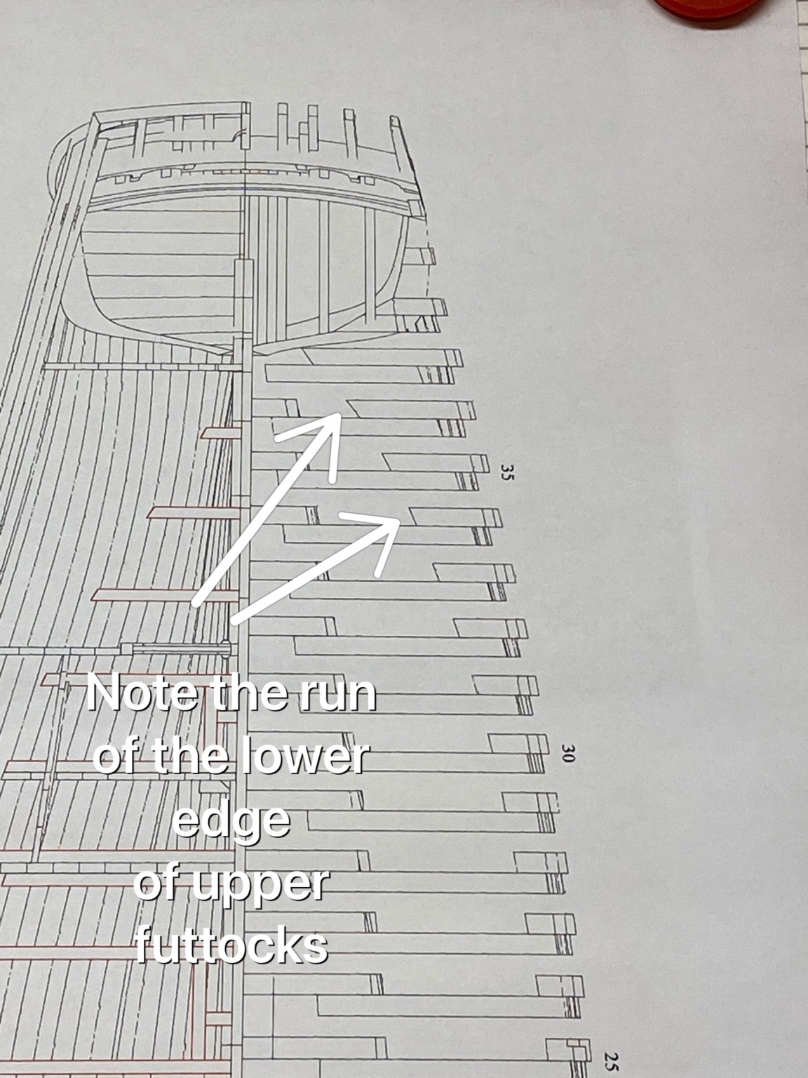
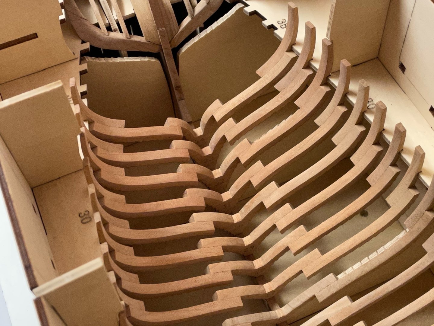
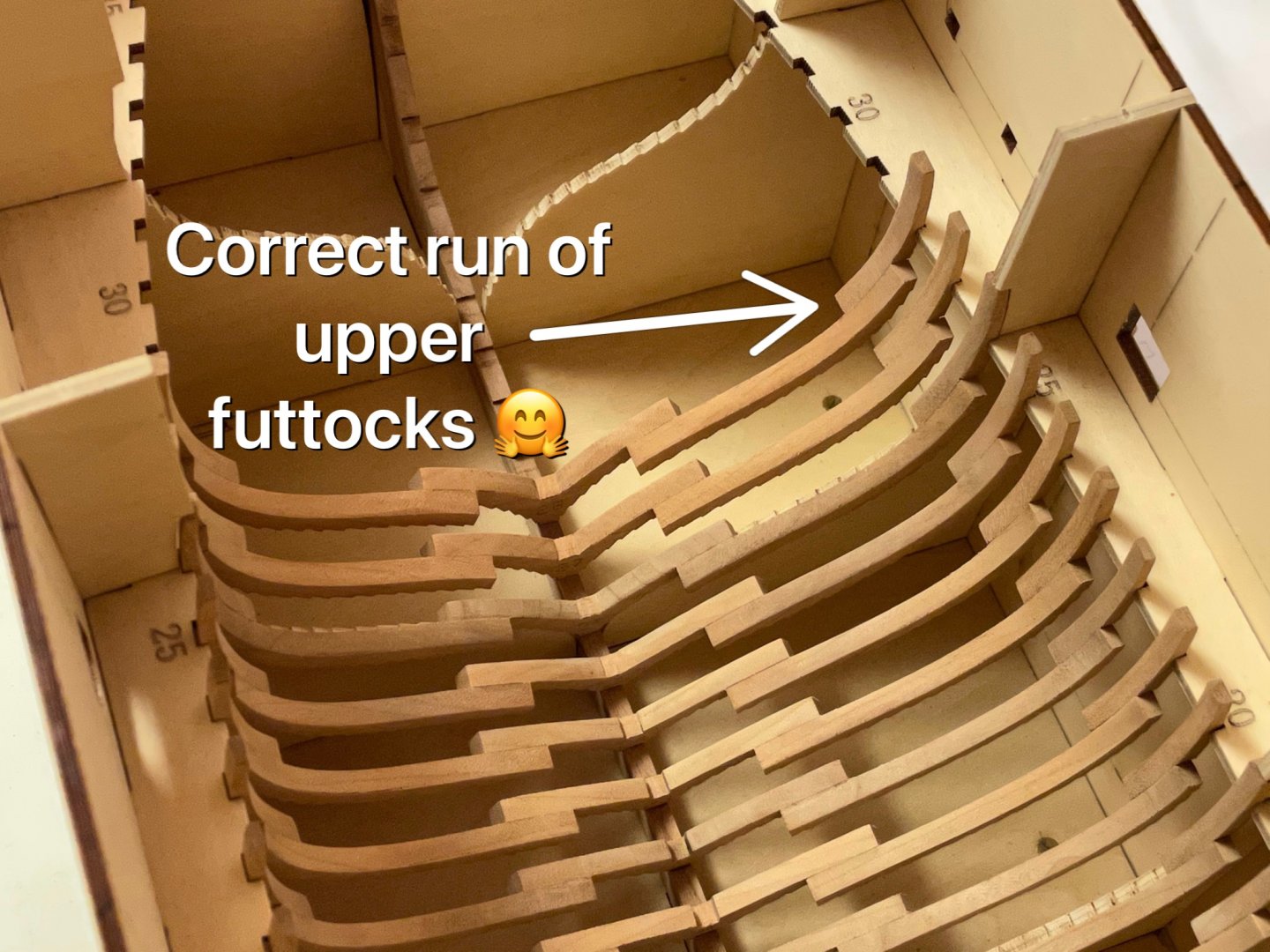
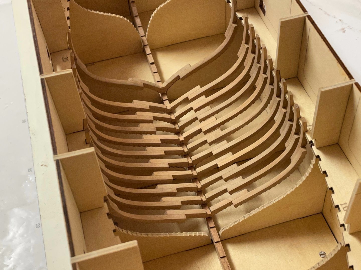
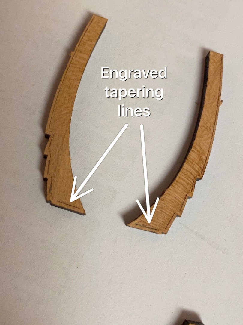
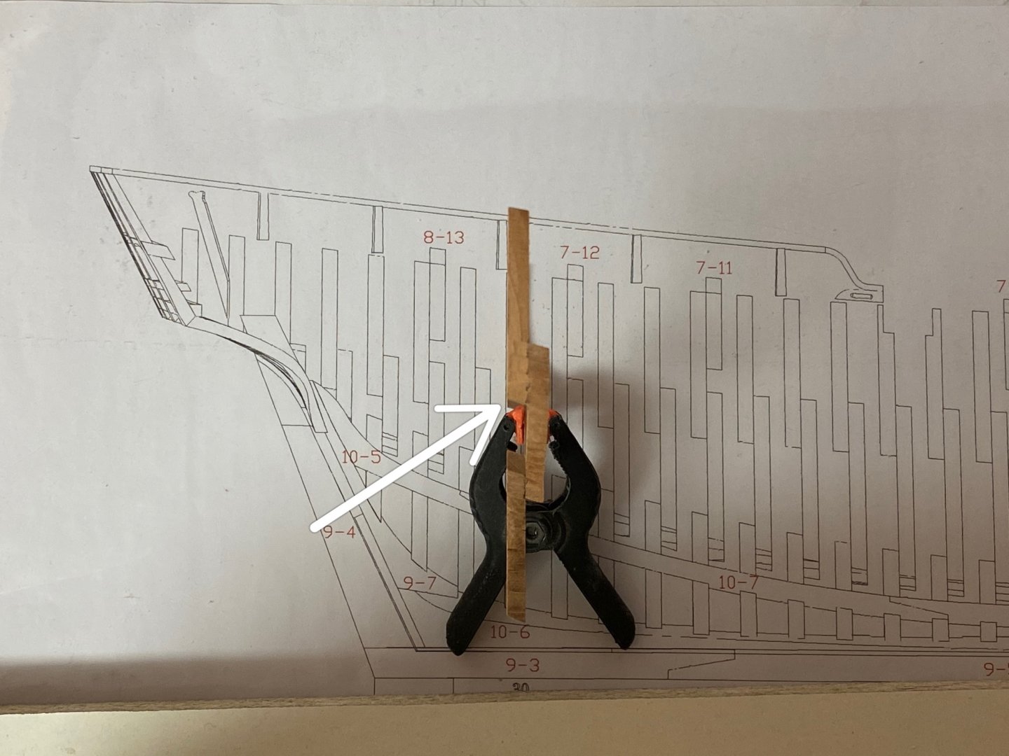
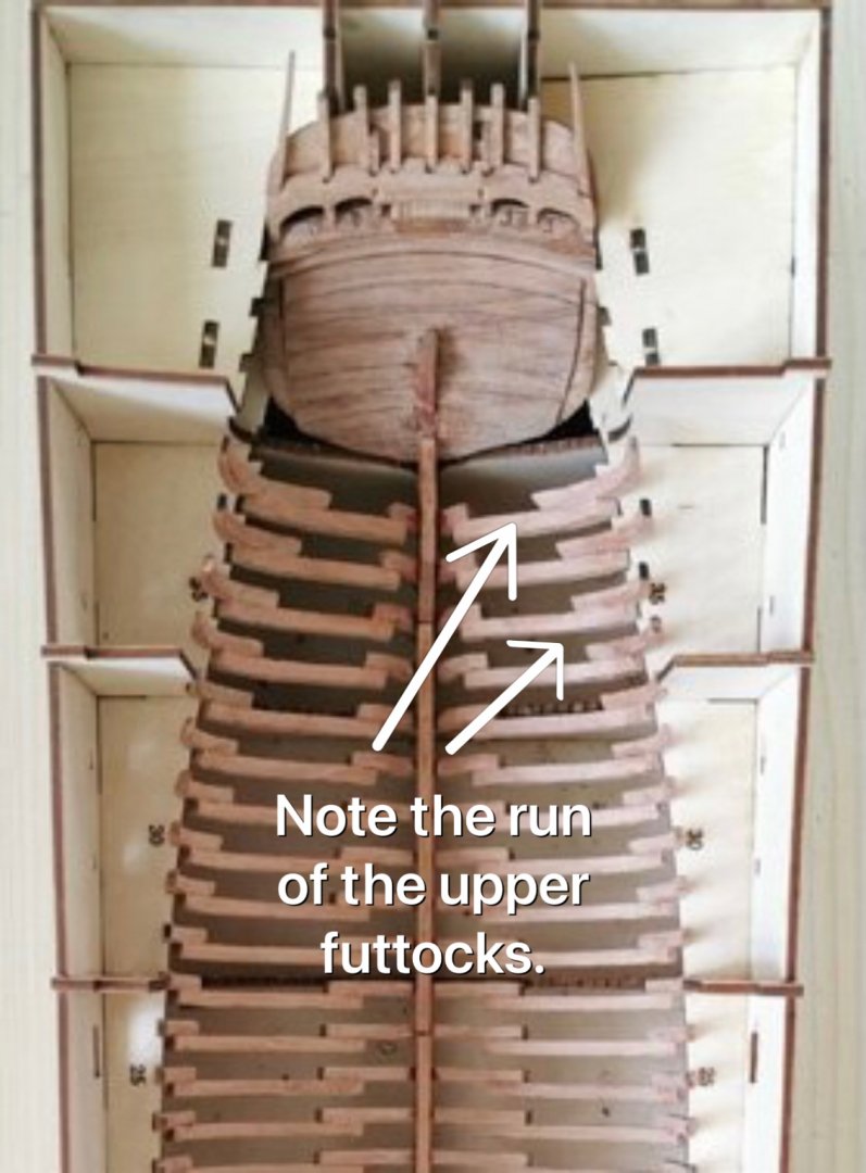
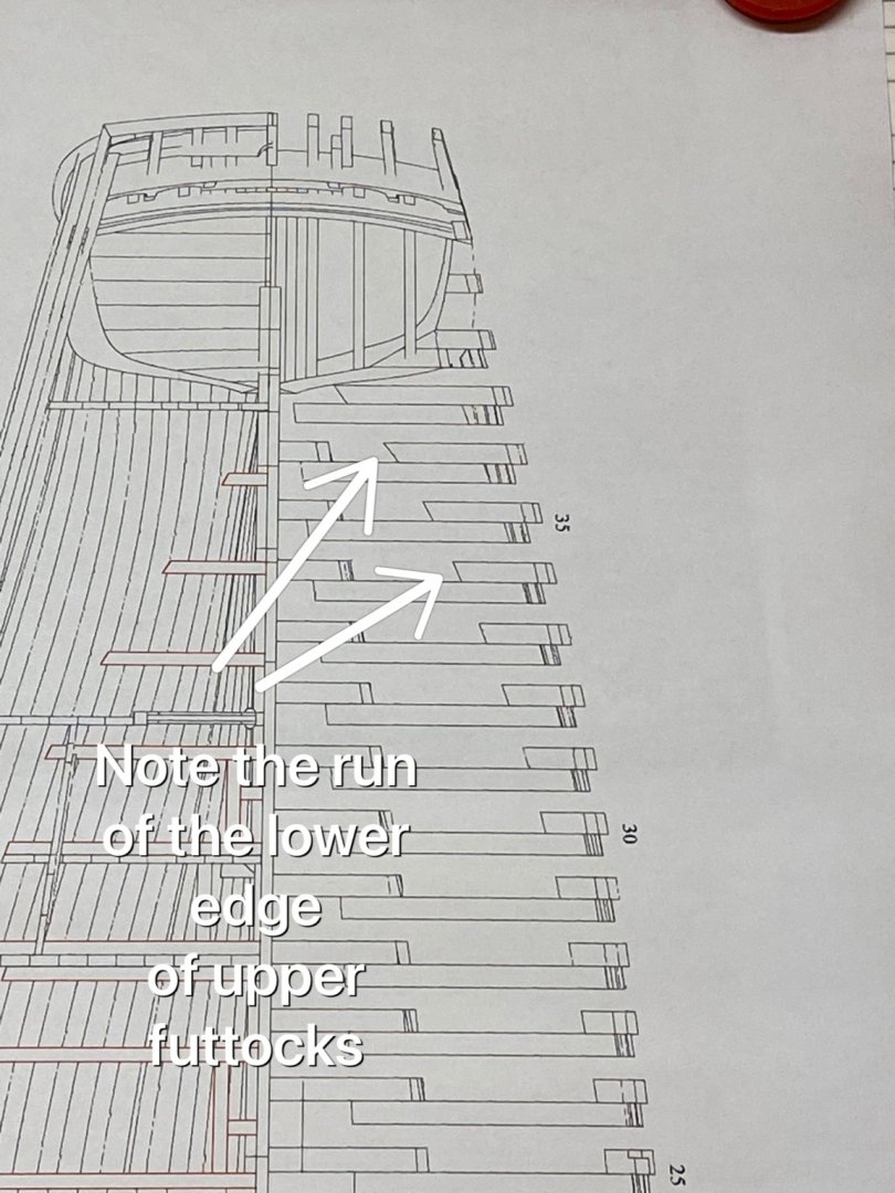
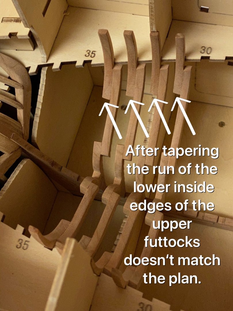
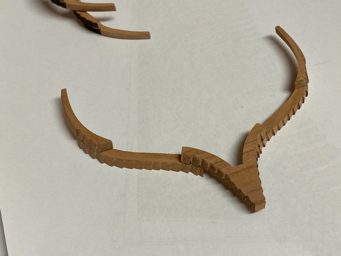
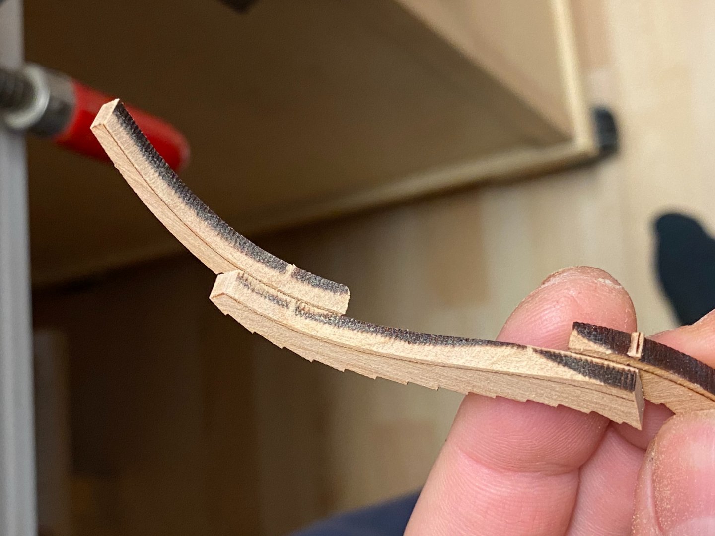
Unfortunately I ran into my first construction problem. I started to build some stern frames which require a lot of tapering. Building instructions of all frames are rare but all parts have tapering lines already engraved - which means you have to rely on the the correct positions of these. There is a tapering line at the bottom of the rear side of the upper futtocks and I read this that the lower head has to be tapered straight from the opposite edge to this line. But tapering will reduce the width of the part at the lower edge, means the inner edge run from inside to outside. Compared to the plan (side view) after tapering the run of the lower side edge of the futtocks (installed on the frame) matches the plan (although there is a little perspective error). If there was no tapering then the upper futtock edge run would rather look like stairs. But the topside view of the frames 31 - 34 doesn‘t match the plan. Here are the topside plan and a picture of the prototype: And here is a picture of my assembled frames 31 -34. Note the run of the lower inner edge of the upper futtocks - they run quite into the opposite direction and I don‘t get the reason why. So at the moment there are only two possibilities for this that come into my mind. First the tapering angle is incorrect so too much tapering has been made - means the tapering lines were misplaced. And the second is there is no tapering at all and the line has to be ignored. I have contacted Tom from CAF, he has gently replied very fast and showed me some perspective views - but these look like there is no or only some slight tapering at the lower edges of the upper futtocks. But no tapering would hardly match the side view of the plan. Any suggestion would be helpful. Best regards, Andreas P.S. Fortunately these are the only tapered frames I have made so far.
-
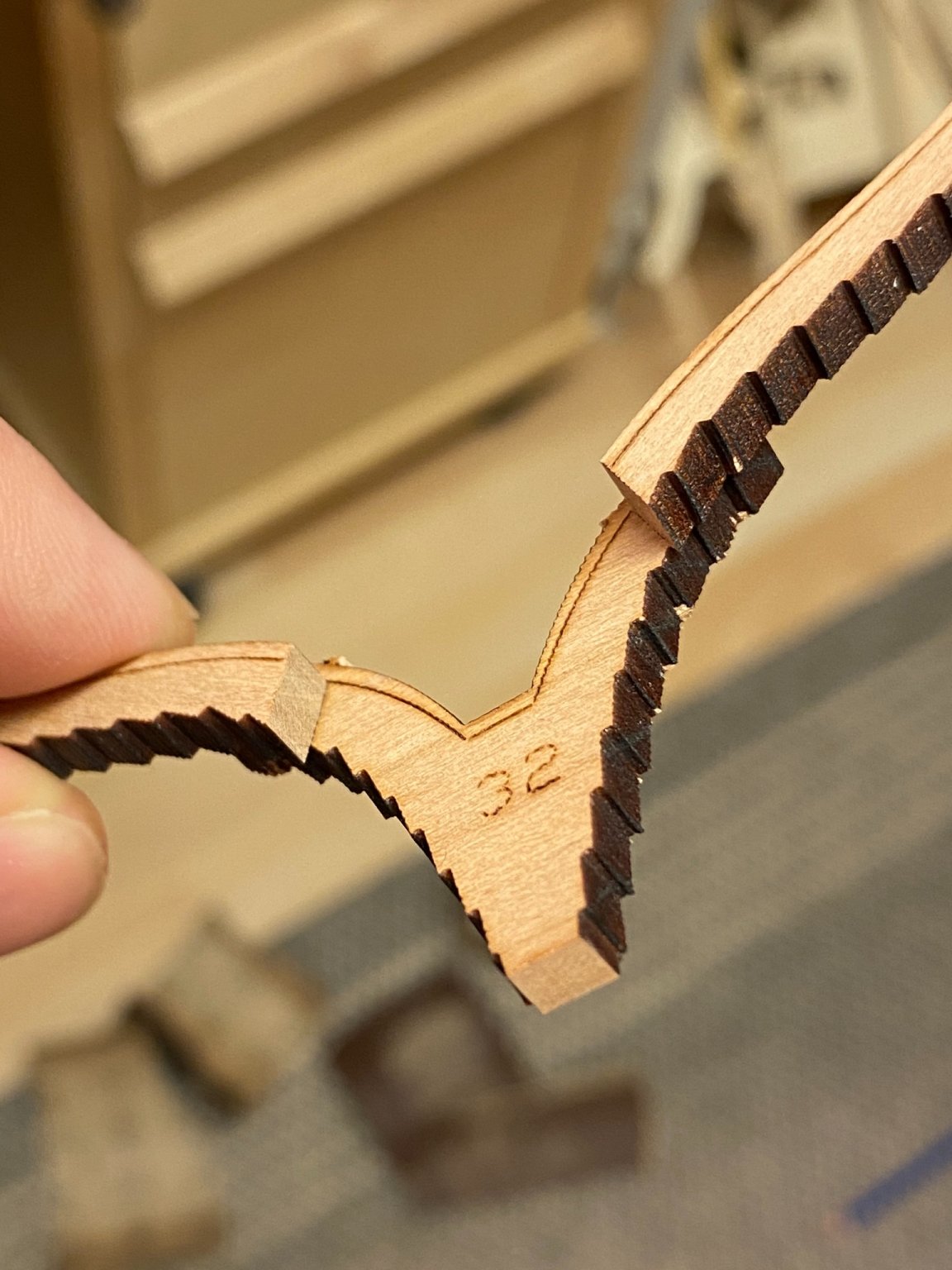
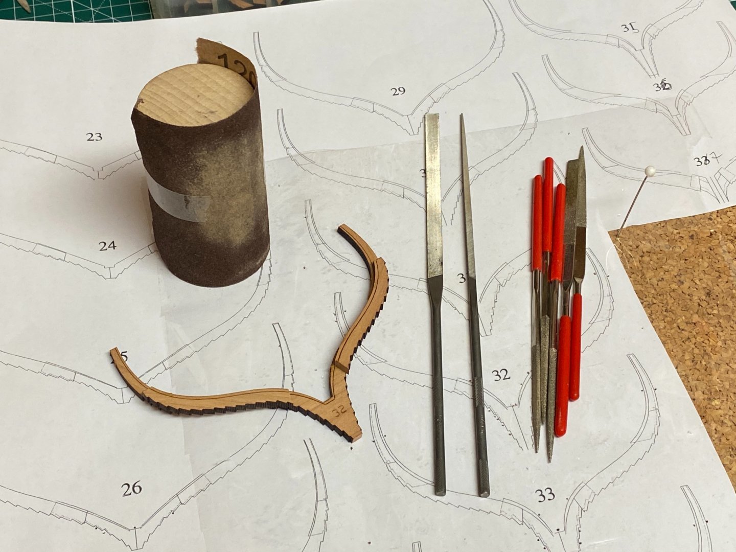
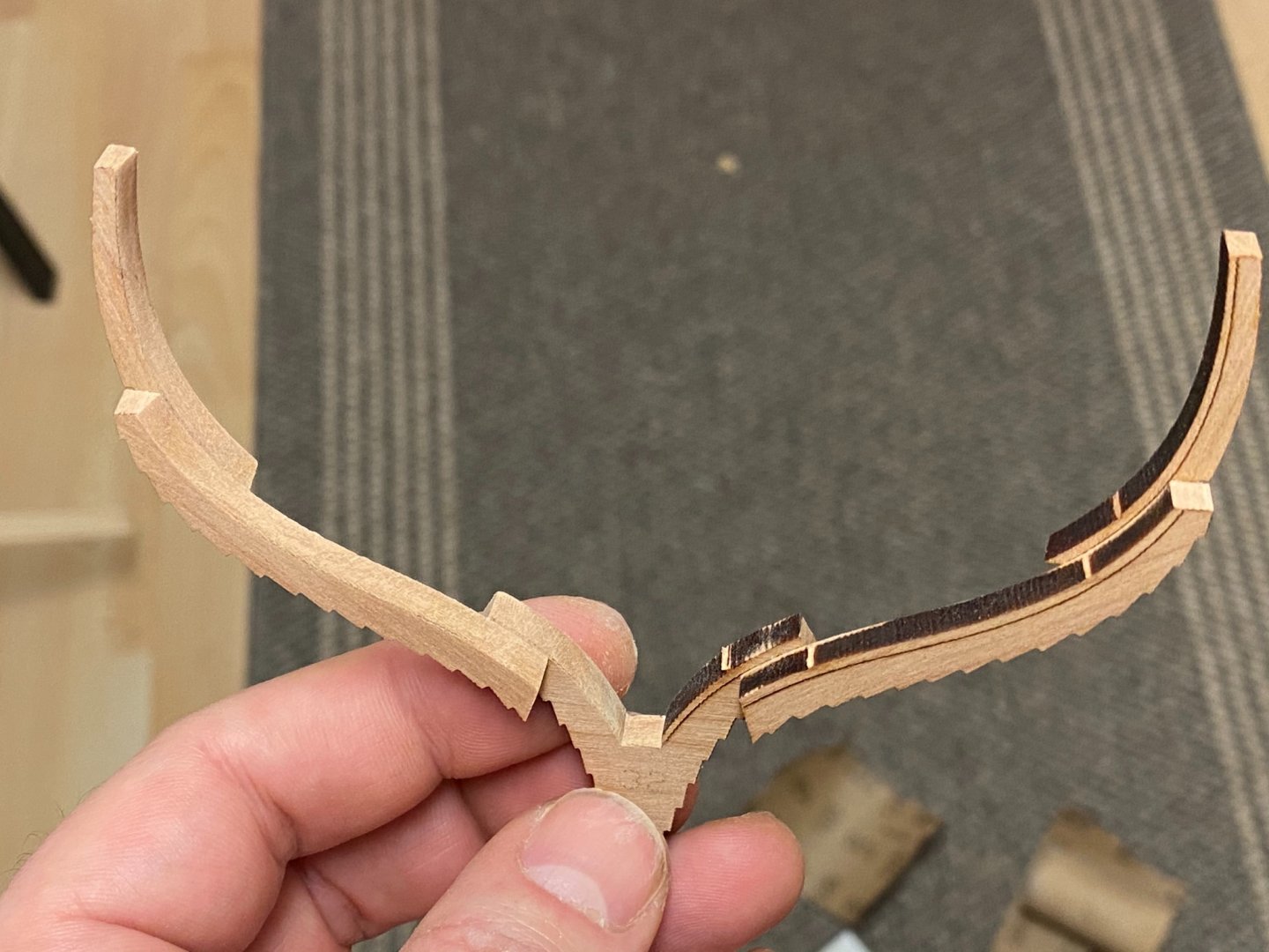
After the glu has cured I use 120 grit sandpaper wrapped around a round wood to sand and taper the inner side first. Using power tools (i.e. a dremel) might take off to much wood because the cherry wood is rather soft. So I can keep a better control doing this by hand. I start with an rather wide angle to remove the laser char close to the tapering line. Then the angle is adjusted to cover the whole surface. The tapering lines are already marked by laser. Half way done.. .. and the other side as well. The last step is to remove the laser char from the steps that will later hold the planking. The steps have to be tapered too but all tapering lines are engraved by laser. I use different needle files, diamond-plated first for the burned surface and steel ones for finish. The finished frame will look like this. Another sanding can be done with 320 grit sandpaper to remove all remaining laser marks and char on the surface. The final adjustment for the steps will be done when all frames are permanently installed to the keel. Meanwhile I have done 9 frames - about a quarter of all frames to be done.

-
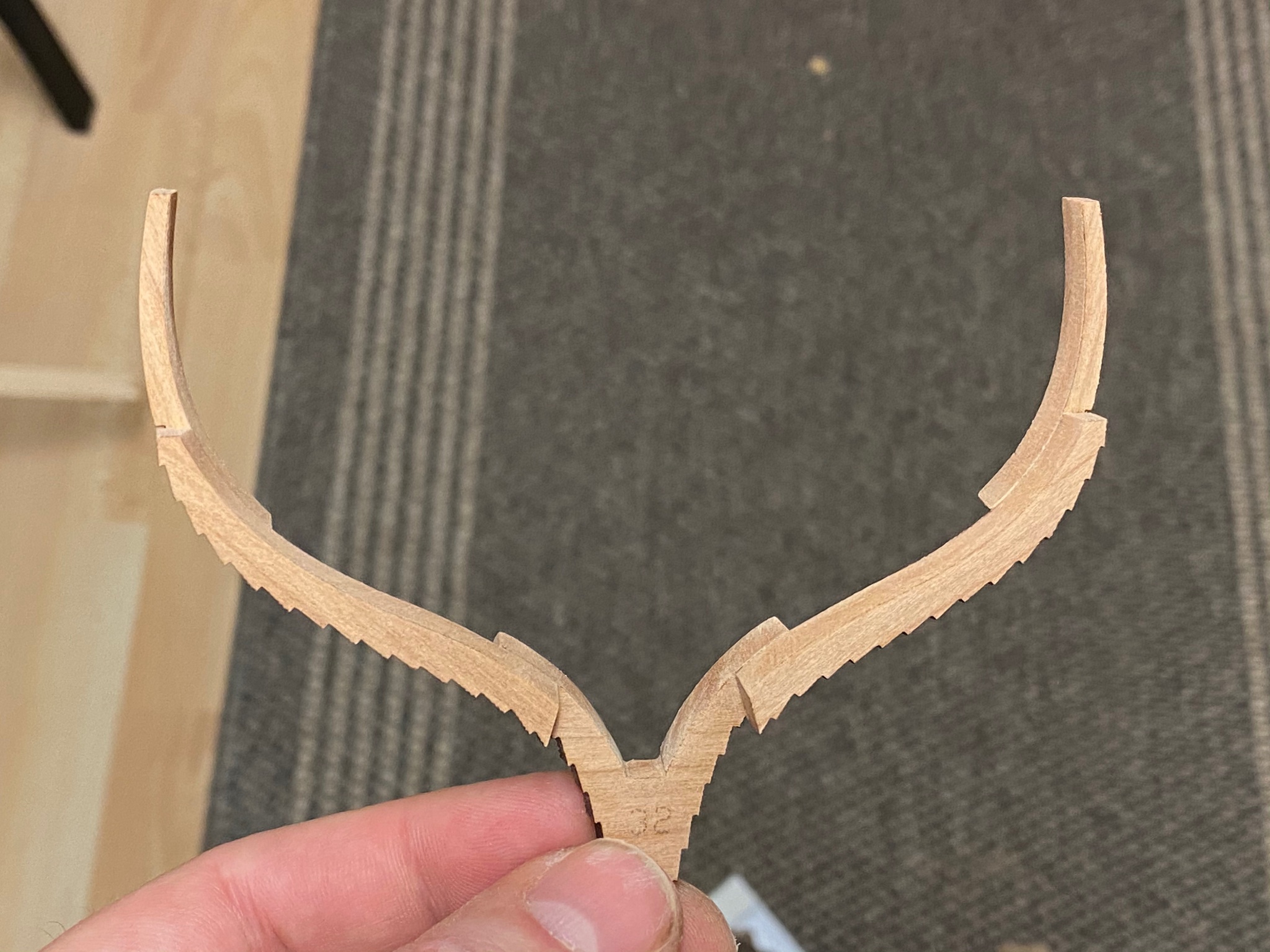
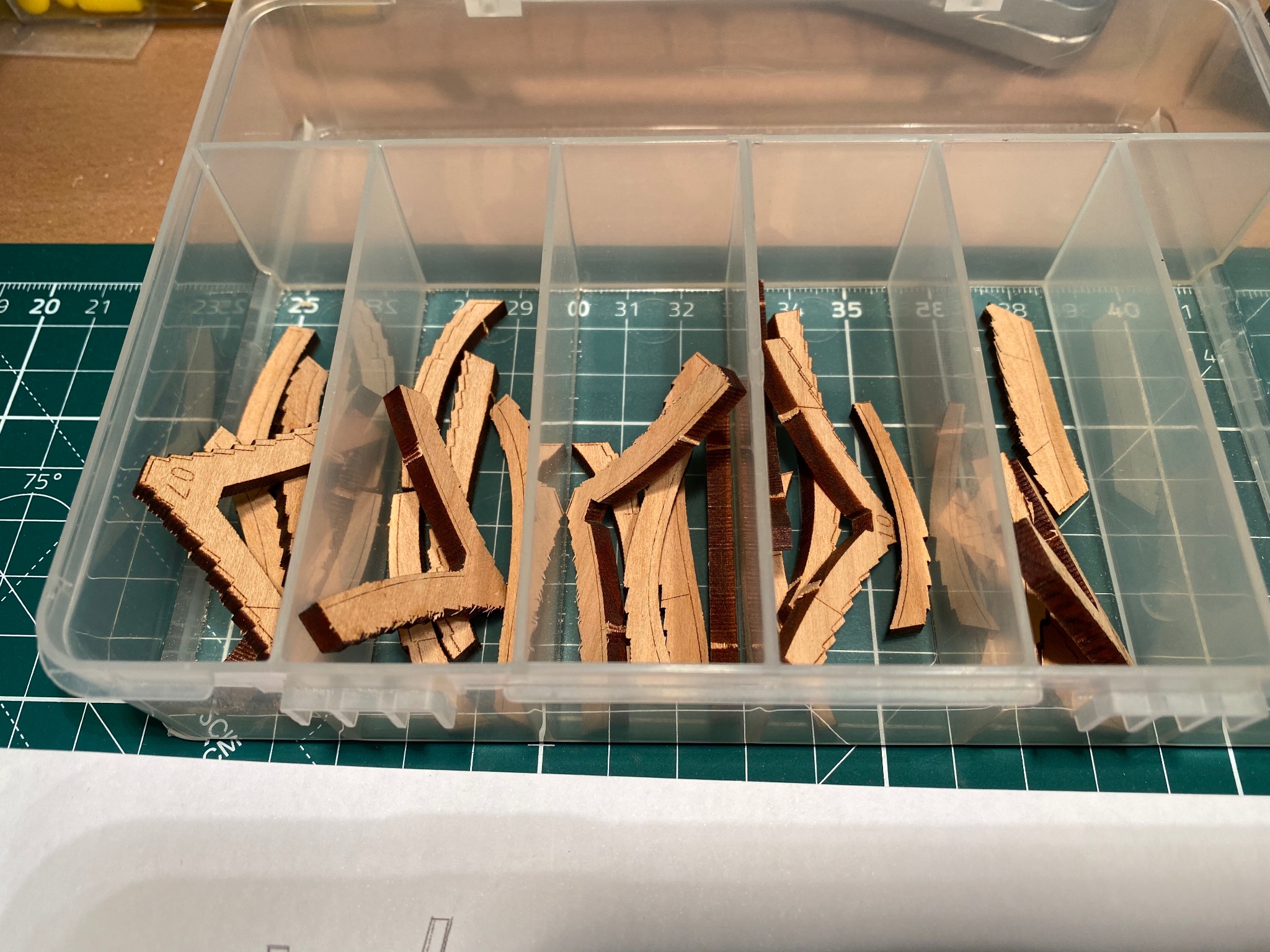
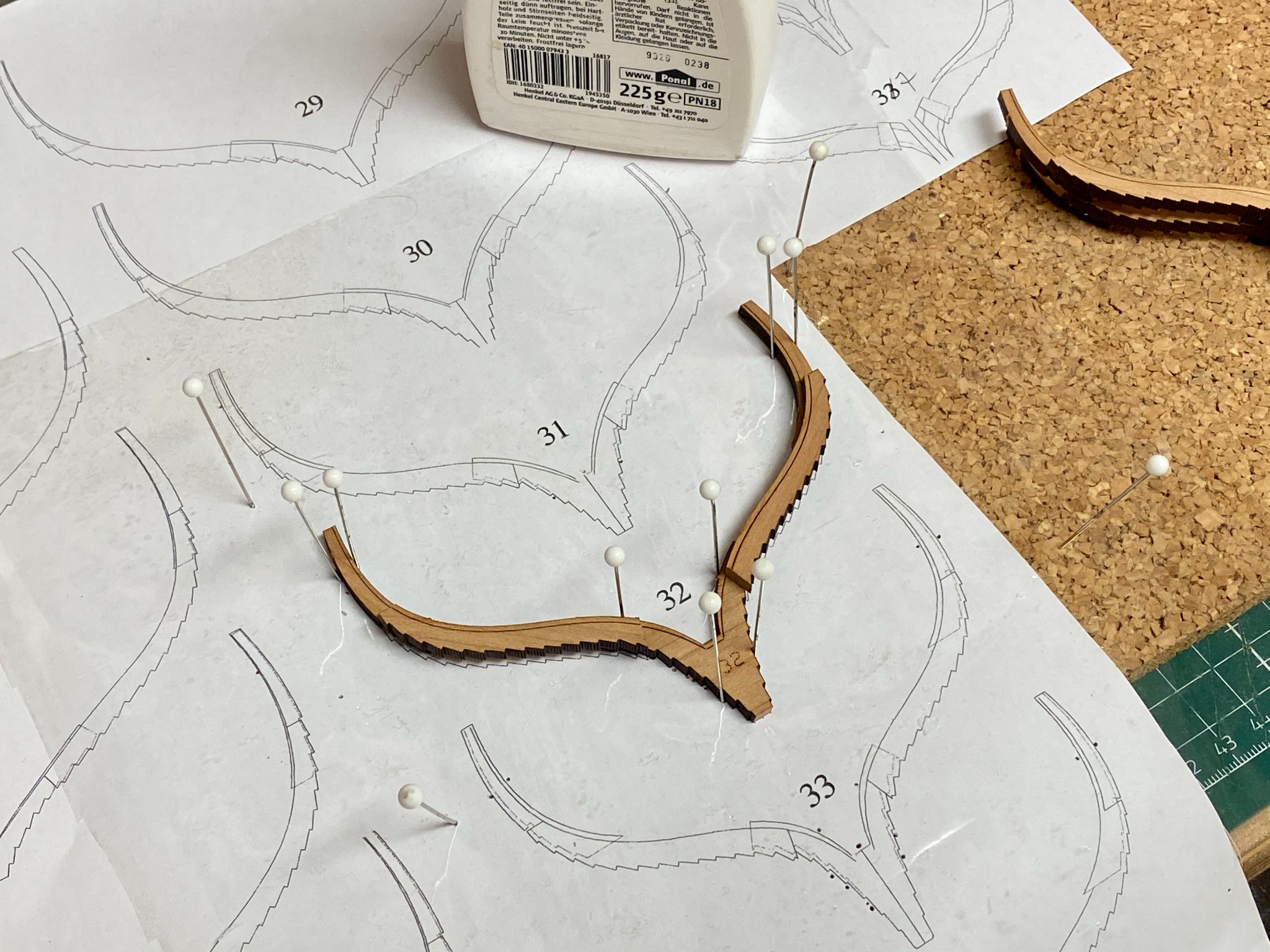
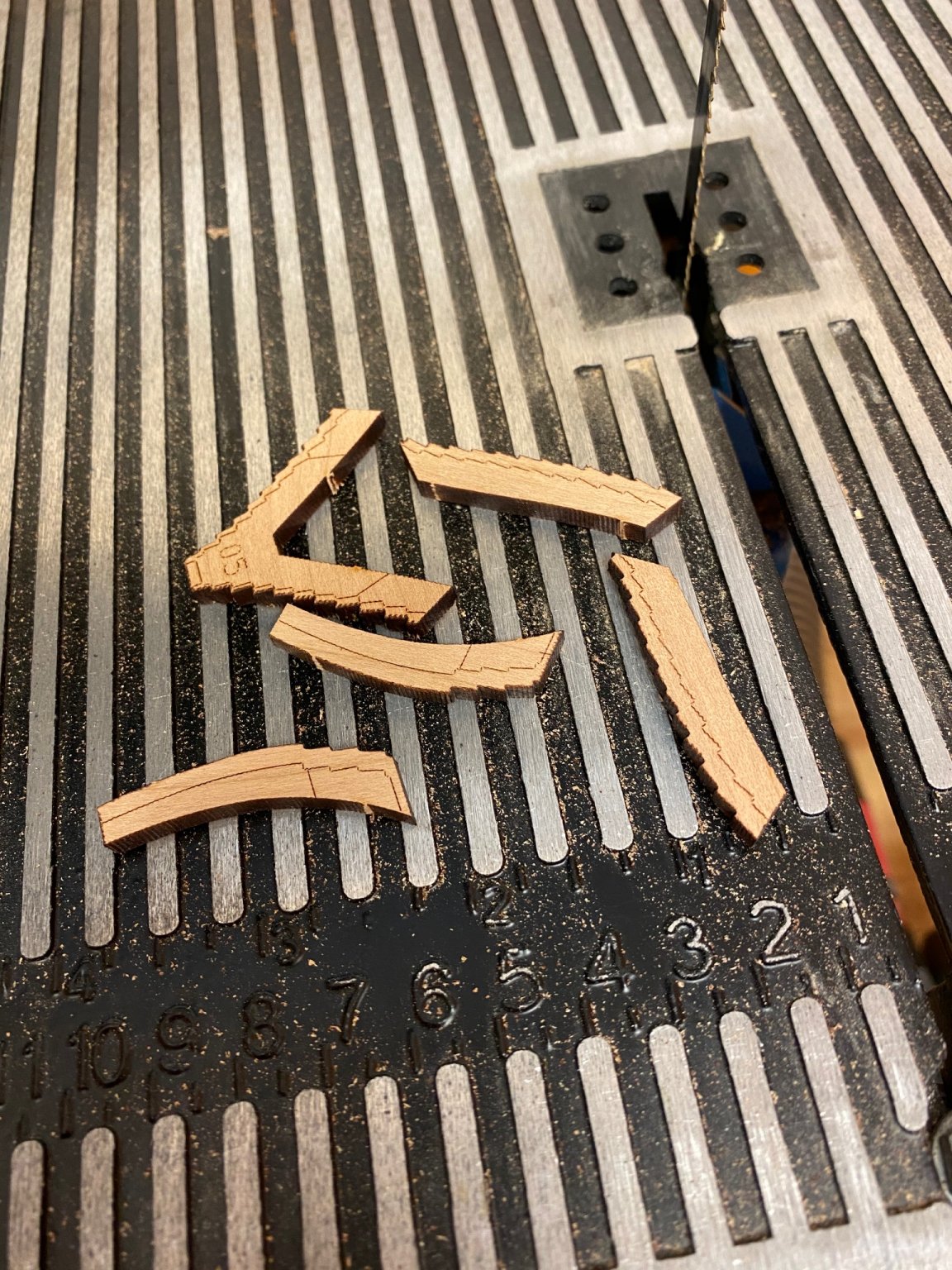
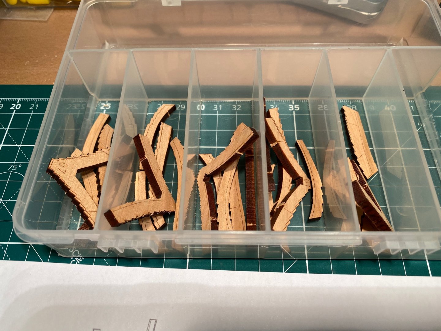
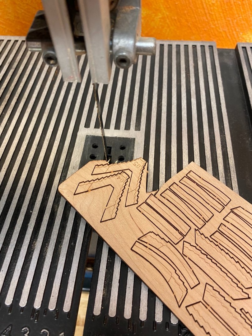
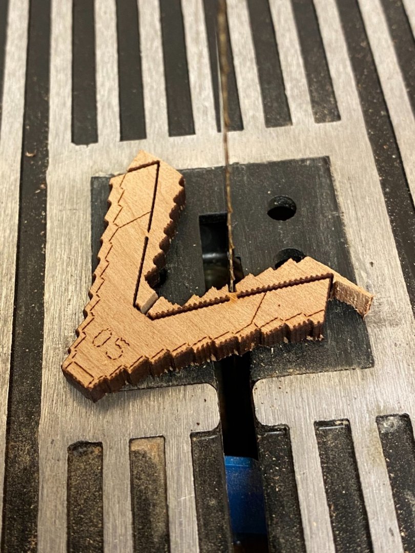
Thank you Yves. Construction of the frames continues. The frames at stern and stem require a lot of bevelling. I might show my way to build these. First I release all required parts of a single frame out of the sheet using my bandsaw to carefully cut the holding bridges. To avoid mixing the parts I use a little box to keep all frame parts together. Then I sand the heads of the parts prior to gluing them together because these areas are difficult to reach and sand later. The frame is then glued together (frame 32 shown). I use a cork sheet and pins to secure the parts in place.


-
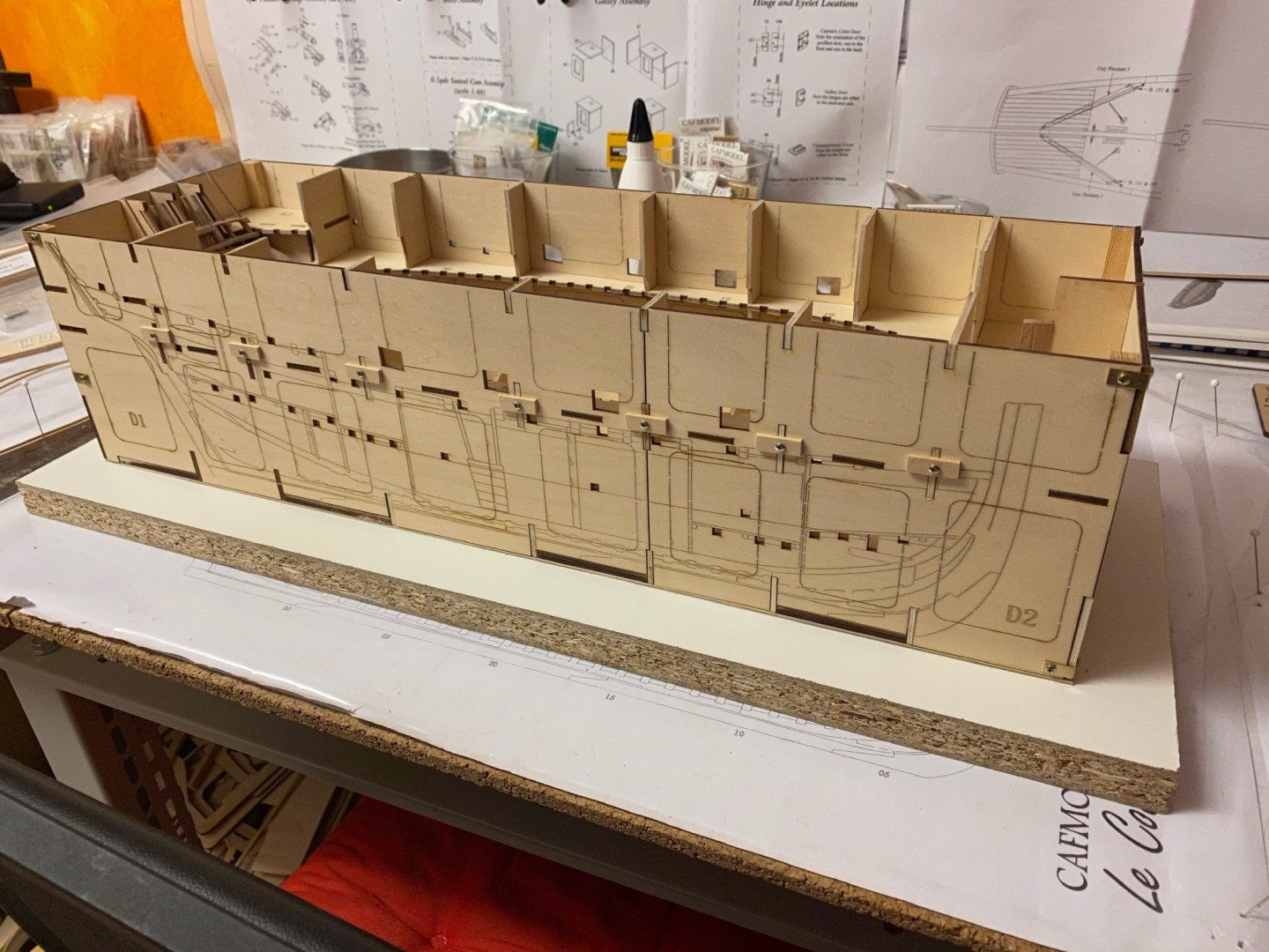
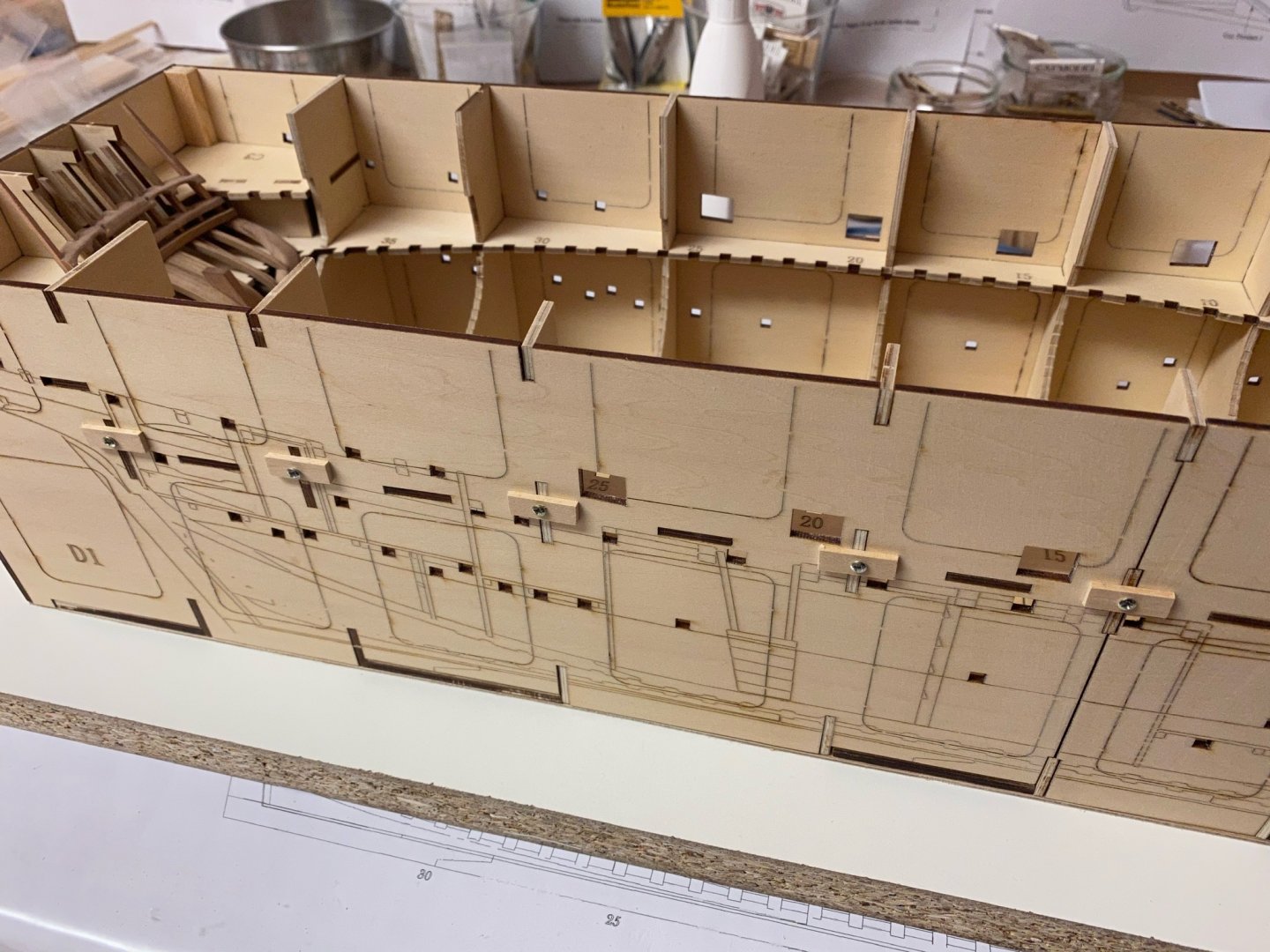
Thank you for your feedback. Yes, the lower one is also my favorite. I‘m going to change the design so the inside of the cabin will be visible through the windows. But I have to consider about how to remove the plywood bulkheads without weakening the structure. I will do that next year. Stay tuned ... and save.
- 64 replies
-
- 3
-
-
- badger
- caldercraft
- (and 1 more)
-
Nice! I will follow on this. The Winchelsea is on my wishlist too.
-
As I'm focussing the Coureur at the moment there is little time for the Badger but I will get back to her in January next year (or earlier if I got tired of building frames). I'm currently thinking about a custom stern gallery and have done some artwork with Corel Draw. There are two versions i prefer but I have not decided yet which one I will use. Stay tuned..and save.

- 64 replies
-
- 5
-
-
- badger
- caldercraft
- (and 1 more)
-
Thank you for the nice words and the likes. Another two frames done. This building step may take some time and I fear I won‘t have anything new to show except frames within the next weeks. As a few frame parts have very ugly defects (black spots) I am going to scratch-build replacement parts as needed but this will also slow-down the progress. The next frames (12 - 15) will have some slight bevelling that has to be done. Stay tuned .. and save.

-
I have done the first three frames today. For an easy start I choosed some of the center frames that don’t need any bevelling (16-21). Sanded the heads of all parts with my disc sander first and then glued all parts together using some pins to fix them. Then I used a needle file and some sanding sticks to get rid of the laser char. Again this took most of the time. Wanted to do six frames but only finished three then I lost my motivation because - boy, this is time consuming and very monotone stuff. Will finish some more tomorrow .. stay tuned.


-
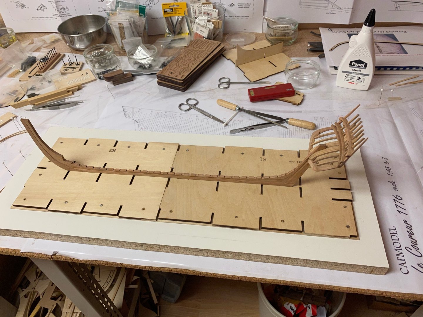
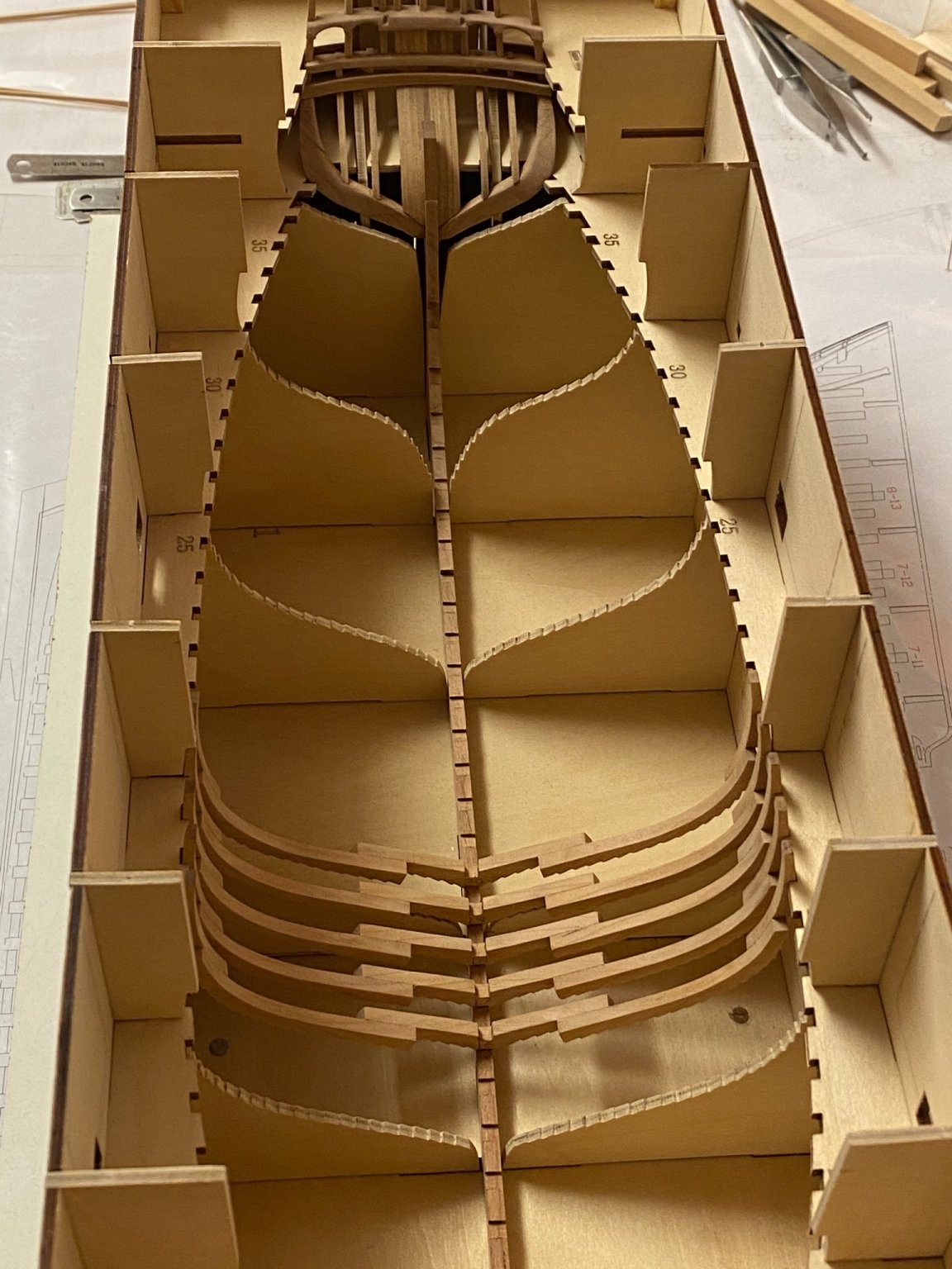
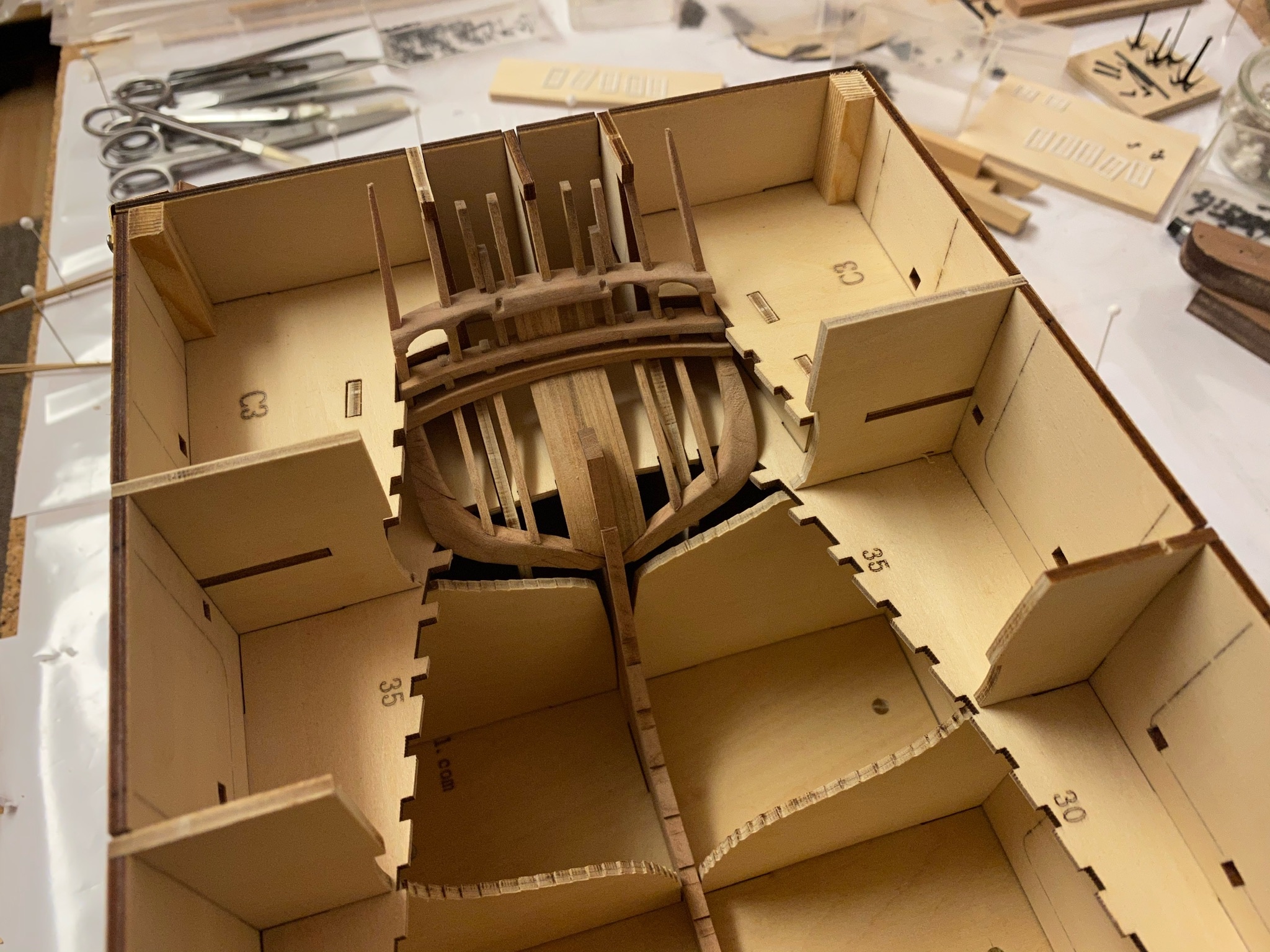
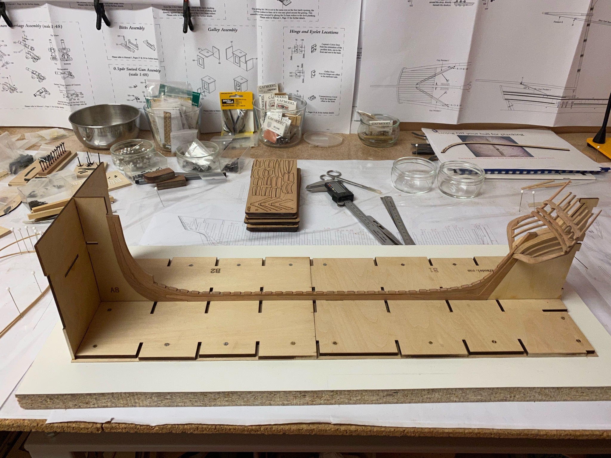
Fortunately setting up the jig was easier than expected. I removed all laser char from the side panels (A1 - A7) so the frames won‘t sit in too tight. Then assembled the jig without glue using some wood screws and scrap wood to hold the parts in place. So I am able to remove the jig if that becomes necessary. Now the keel and stern structure is pretty much locked up. Will start with the first frames next. Stay tuned .. and save.
-
Very nice solution to replace the casting!
-
So this is what I have done so far. I don‘t know if the cant frames are to add at this point or later but as there are Position markings inside the jig I assume they have to be added later during the build to the correct positions. So I will set up the jig during the next days after Christmas and start building the frames. Or just relax for some days... I wish everyone on MSW a merry Christmas and a hopefully better 2021!! Best regards, Andreas

-
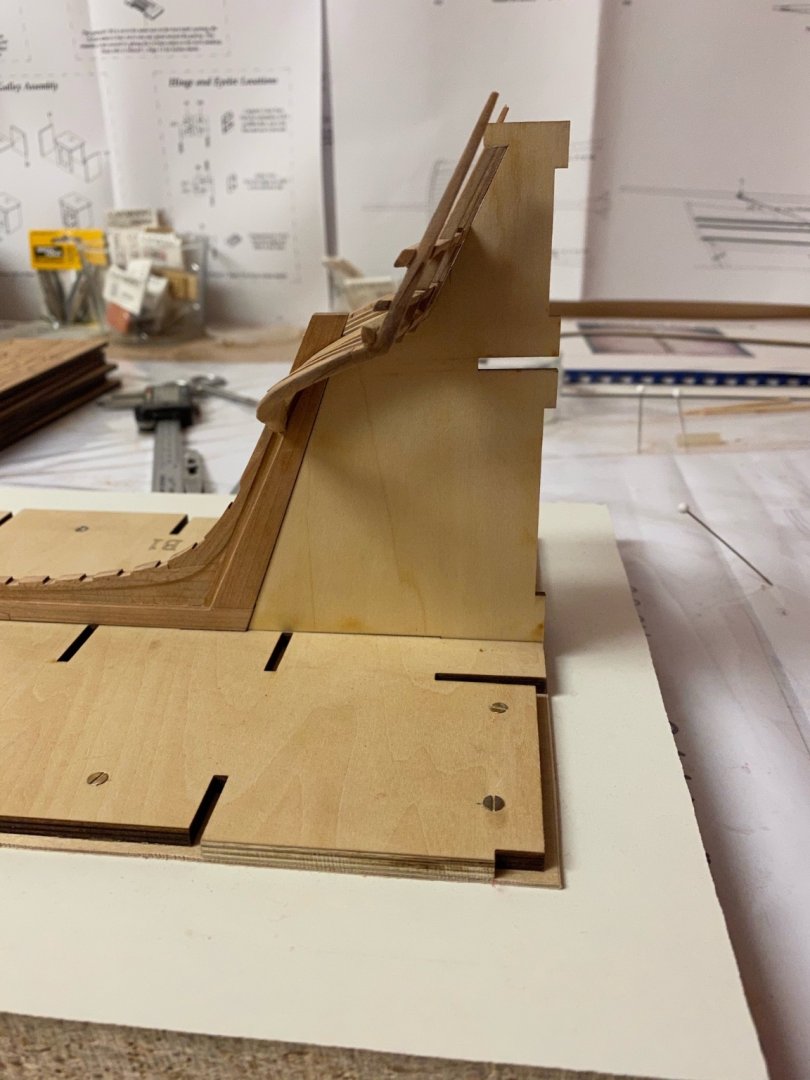
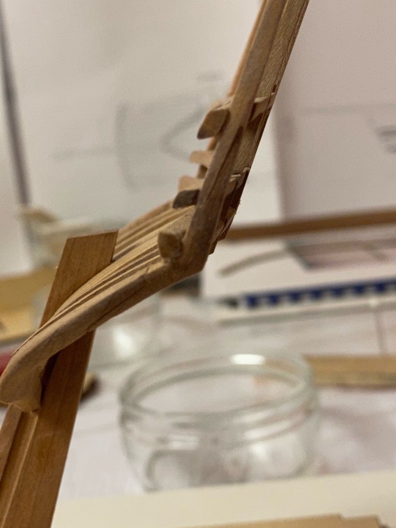
@PoulD: Thank you for pointing on that. Yes, the transom runs with an angle, I’m glad I noticed that during the construction. But it is very difficult to catch with my camera. Here are my best shots.
-
Thank you for the nice comments. @yvesvidal Hm, don‘t know why the extensions are that long. Maybe for better handling while gluing the counter timbers together. They are supposed to be trimmed later. @Ron Burns There is a lot of post-processing needed - even for the CNC-milled parts. And you have to care a lot about not sanding too much substance off when getting rid of the laser char. But until now the overall part-fit is very good.
-
And after adding all missing stern frames the assembly is finished. Next thing will be assembling the jig and start building the frames. Stay tuned .. and save.