HOLIDAY DONATION DRIVE - SUPPORT MSW - DO YOUR PART TO KEEP THIS GREAT FORUM GOING! (Only 36 donations so far out of 49,000 members - C'mon guys!)
×

captain_hook
-
Posts
685 -
Joined
-
Last visited
Content Type
Profiles
Forums
Gallery
Events
Everything posted by captain_hook
-
 You‘re making great progress, very nice build. The Swan-Class is a favorite of mine, hope you don‘t mind if I follow along your build.
 -
Wow, you‘re a very fast and clean builder. Is it all depending on your own high building skills or does the kit go together that easy?
- 355 replies
-
- 2
-

-
- vanguard models
- Sphinx
- (and 1 more)
-
Absolutely beautiful. Do you feel a little sad to give away your ‚commissioned’ work to customers? I ask myself if they will appreciate all the hours and research you spend into that little project.
- 433 replies
-
- 4
-
-
- open boat
- small boat
- (and 1 more)
-
Very nice. I like the „painting with wood“ approach and the little cut out with simulated frame structure.
- 399 replies
-
- 1
-
-
- winchelsea
- Syren Ship Model Company
- (and 1 more)
-
Very nice progress. Do you make your own laser-cut parts and if you do, may I ask which laser-cutter do you use?
-
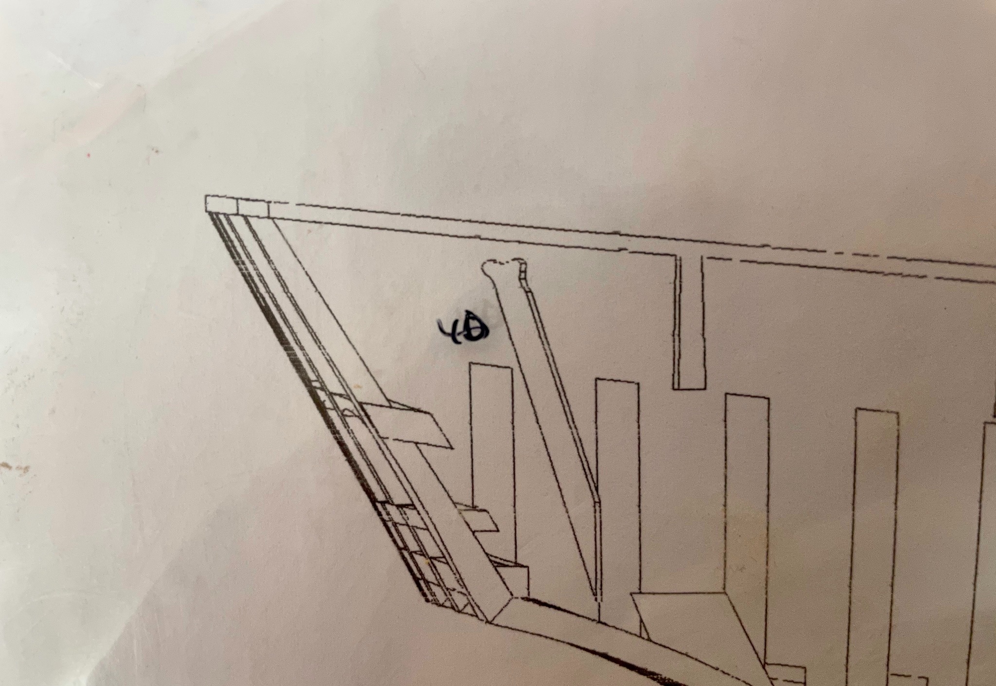
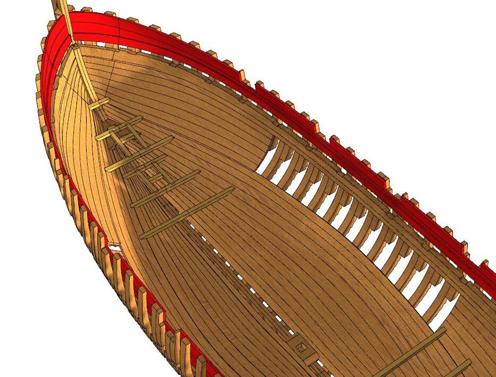
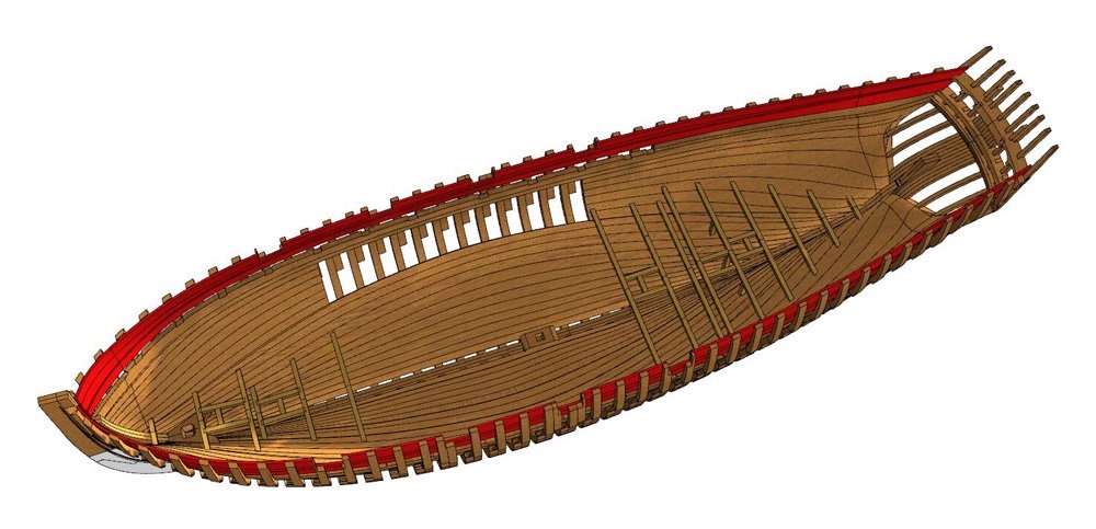
Thank you very much, Pete and Yves. Well, I should think about that. The inner hull is supposed to be planked with the upper center area left unplanked on both sides. Here are two CAD-drawings provided by CAF showing the completed inner planking. So you will be able to take a look inside. But that means I have to leave at least one side and the corresponding deck partial unplanked, which will be most likely the port side. But I haven‘t decided yet ..
-
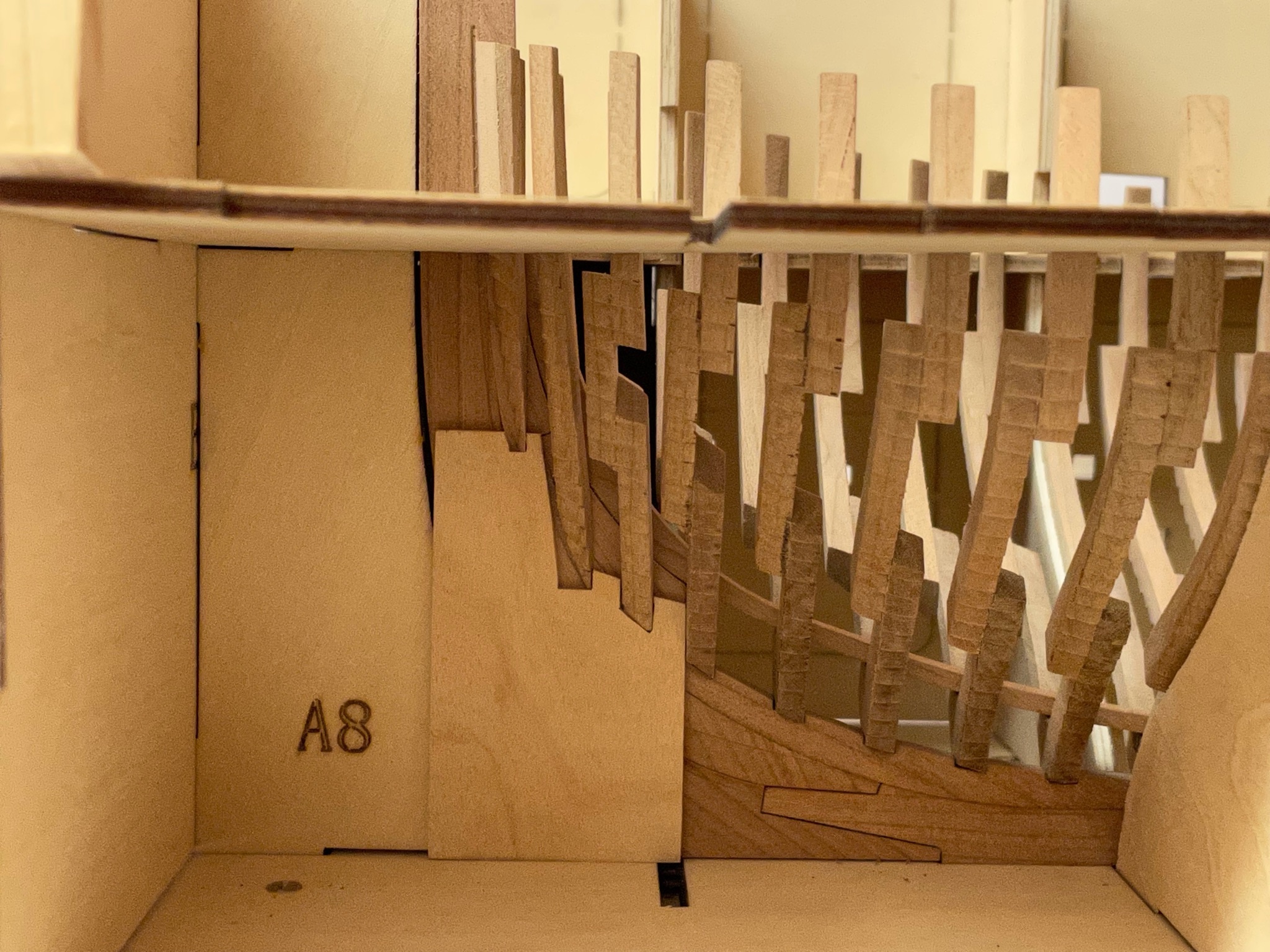
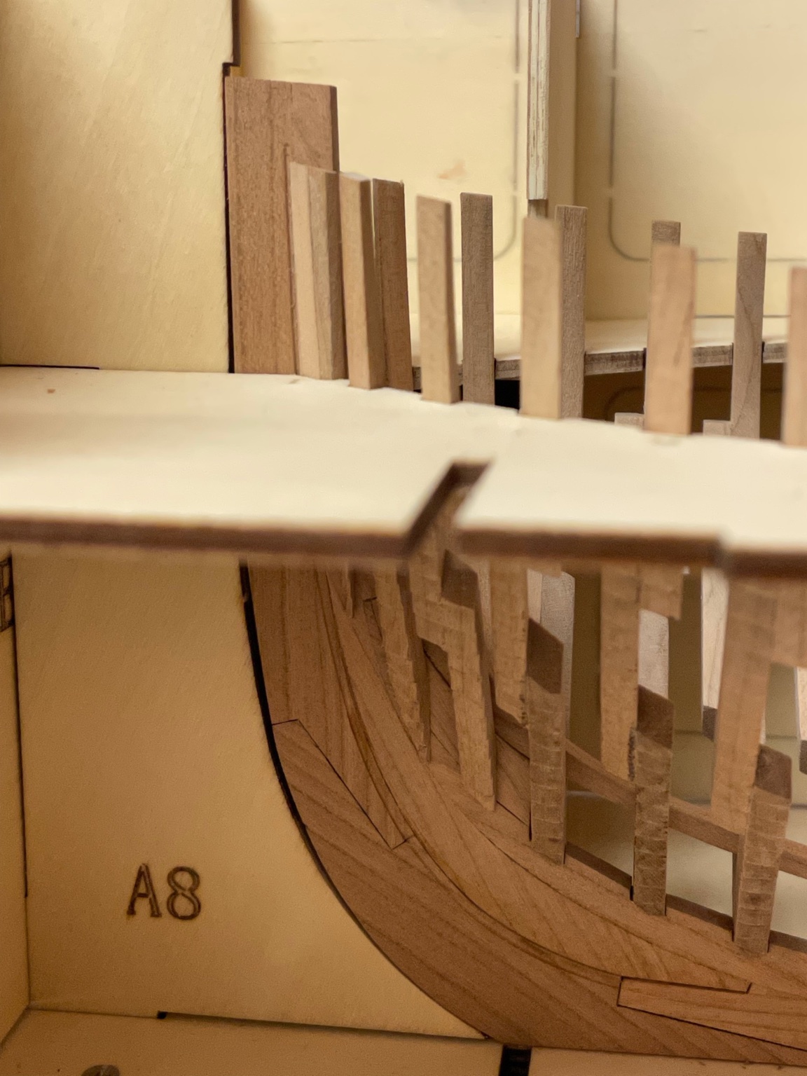
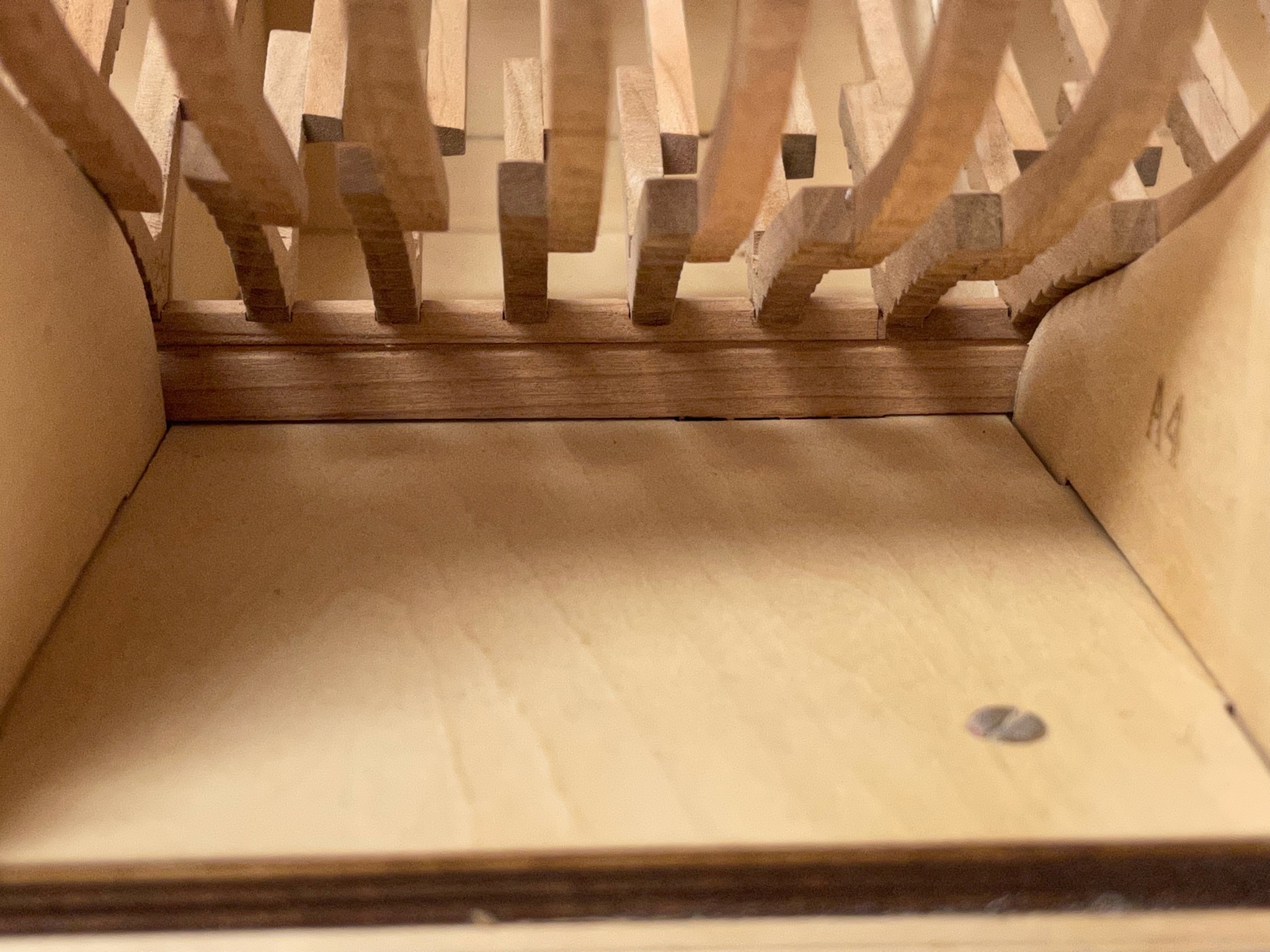
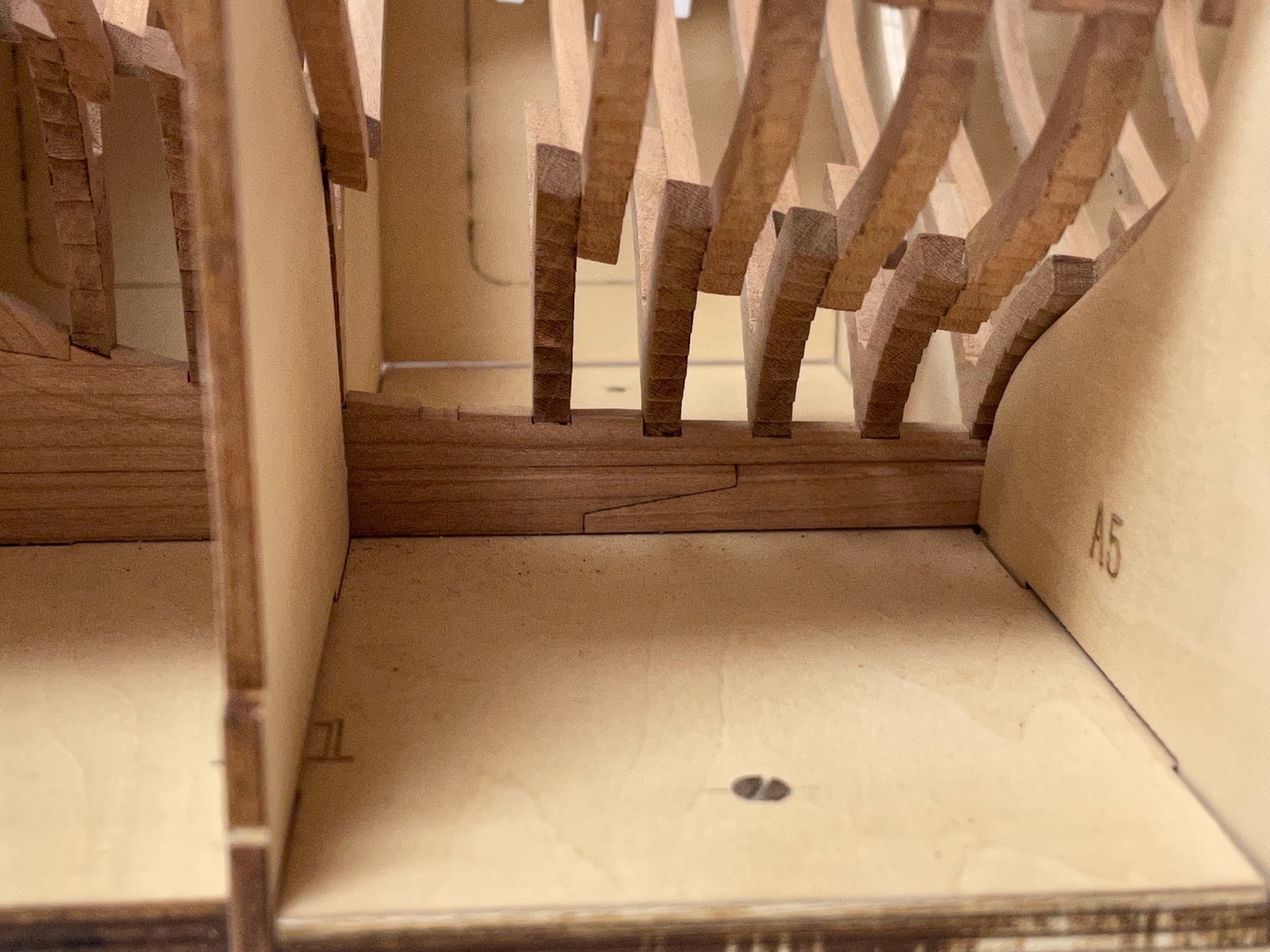
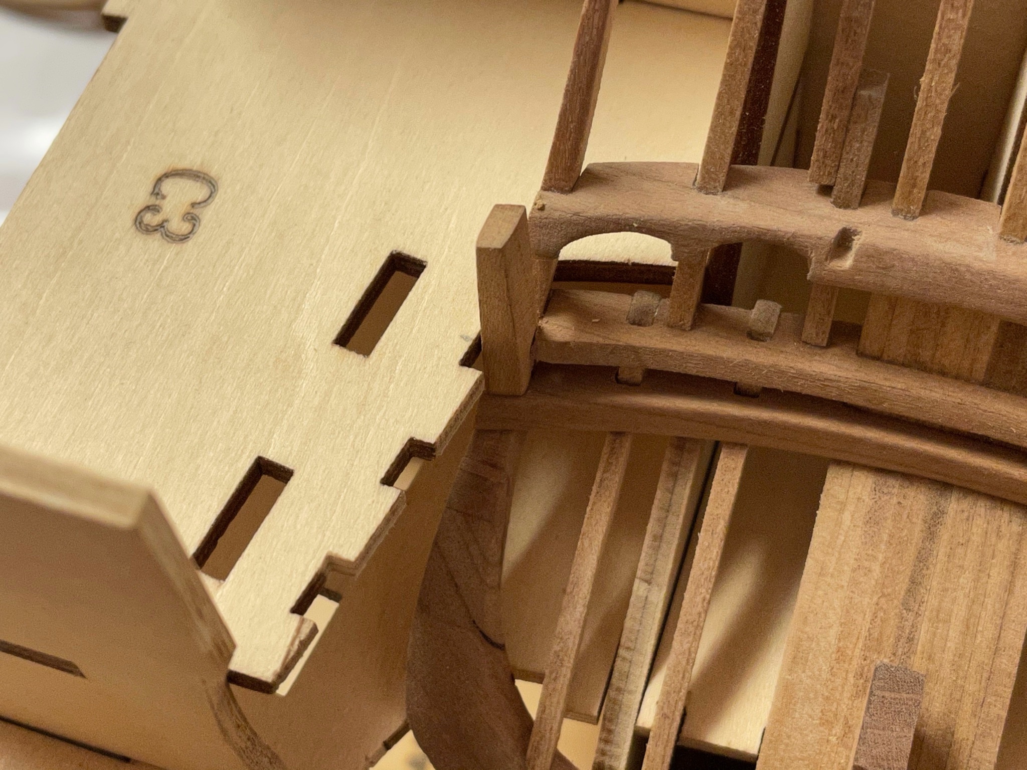
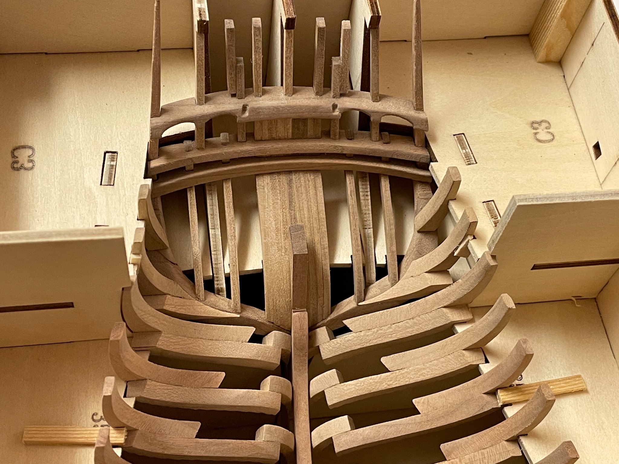
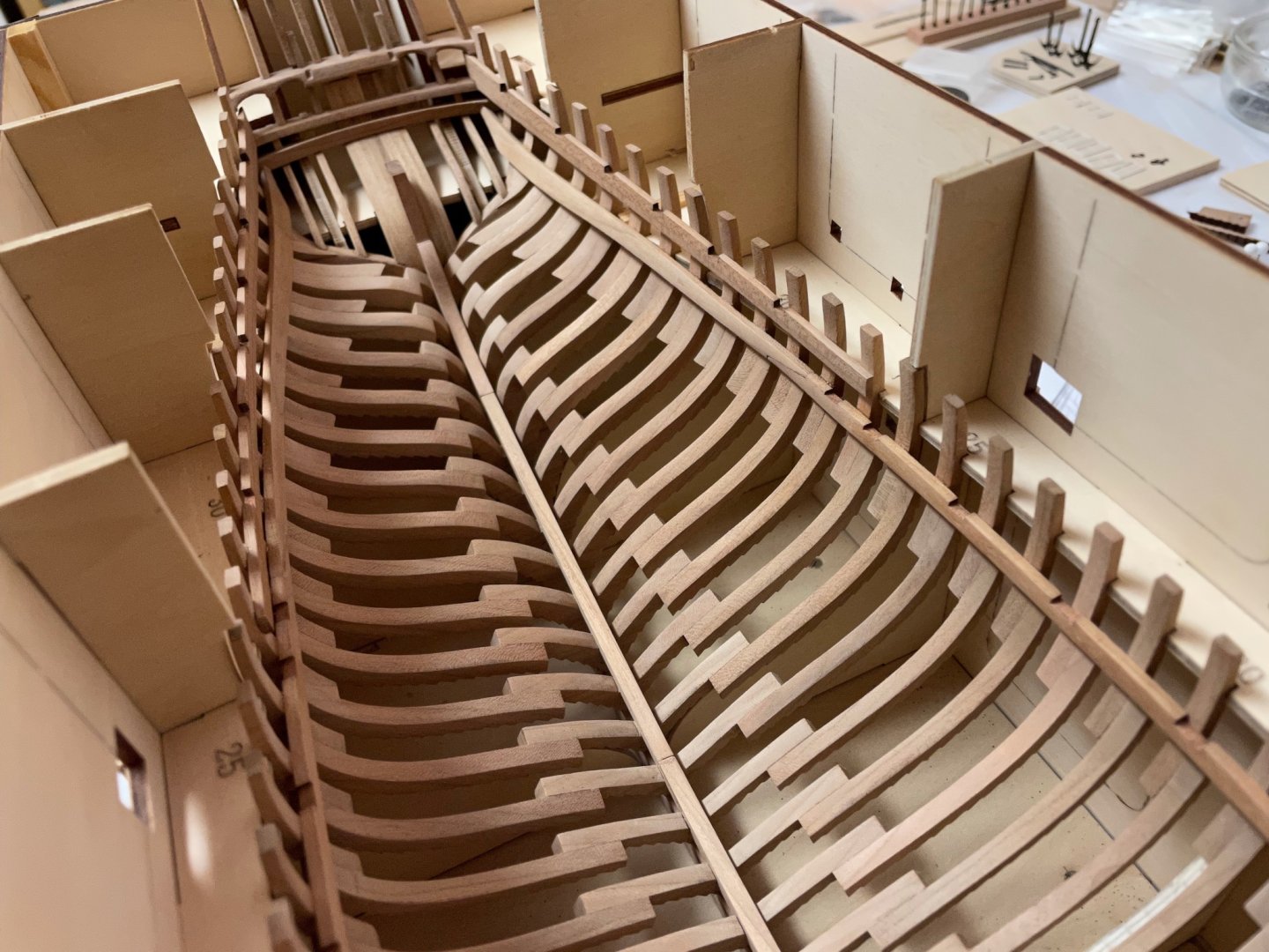
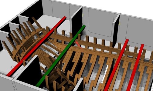
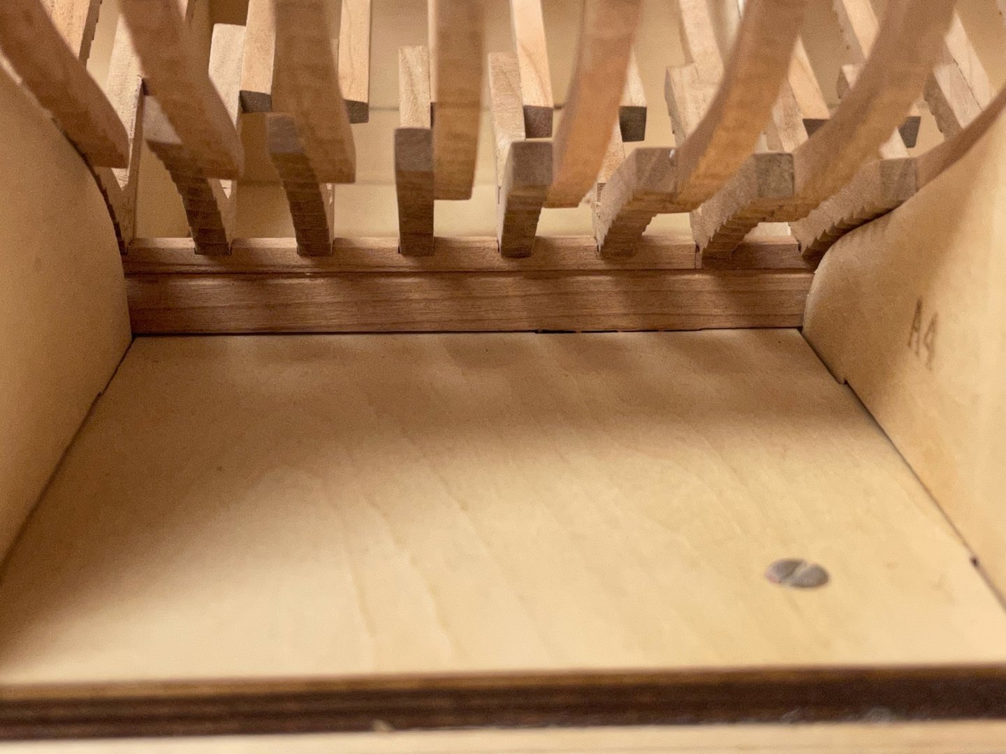
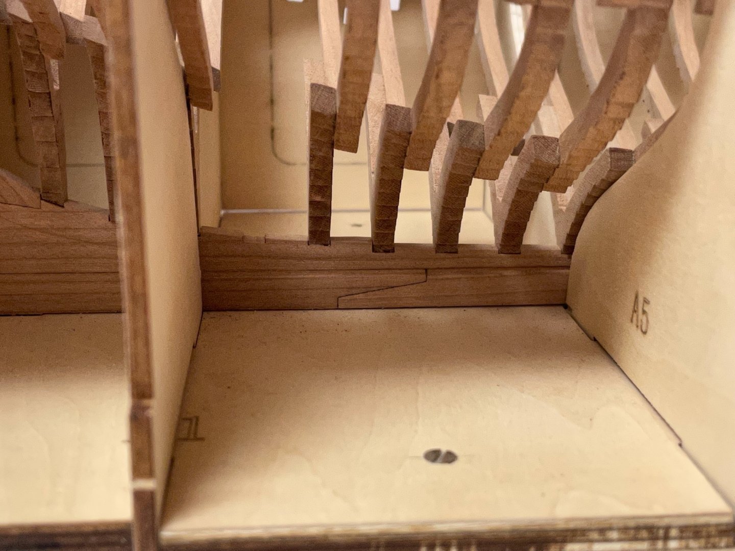
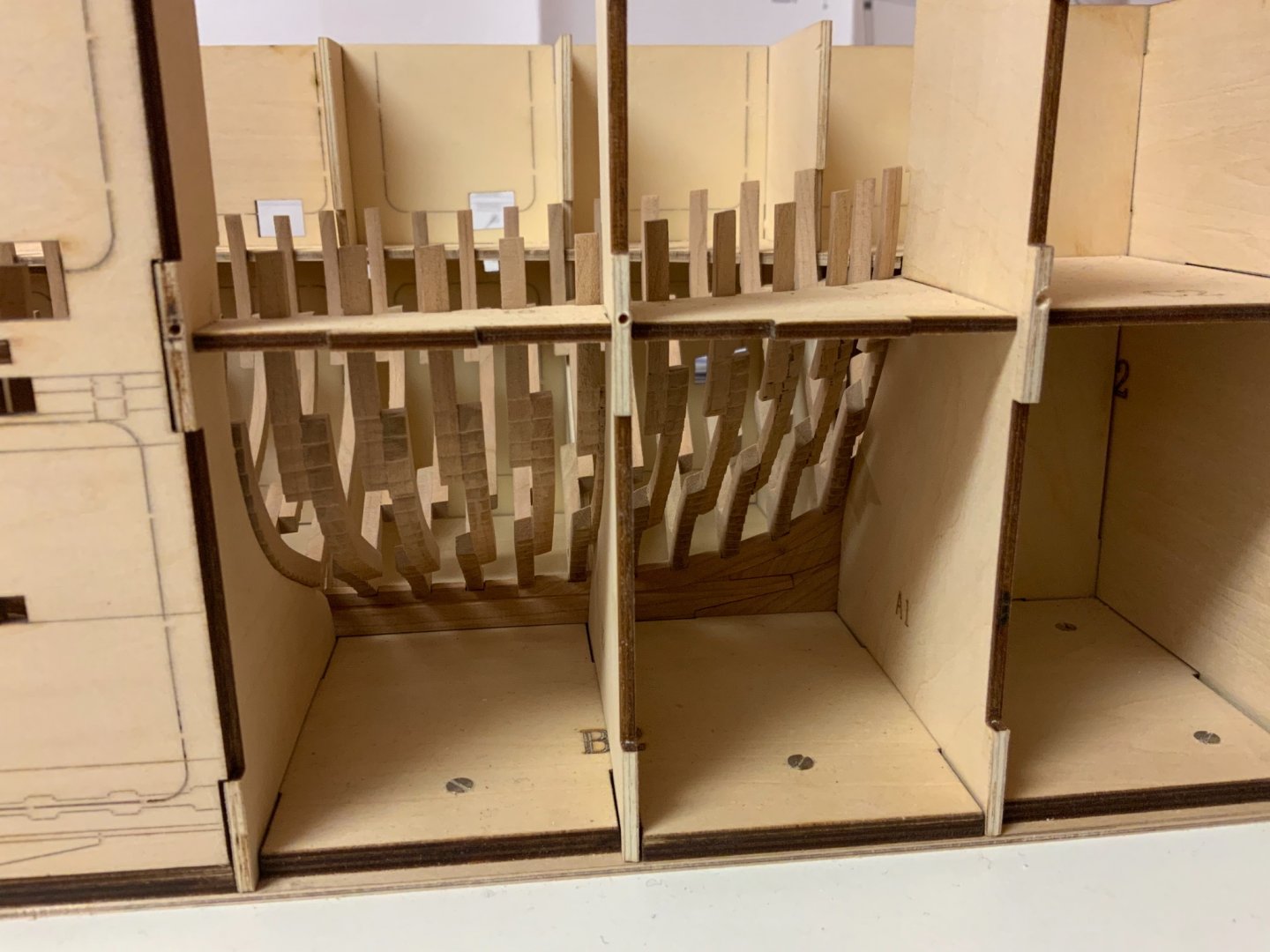
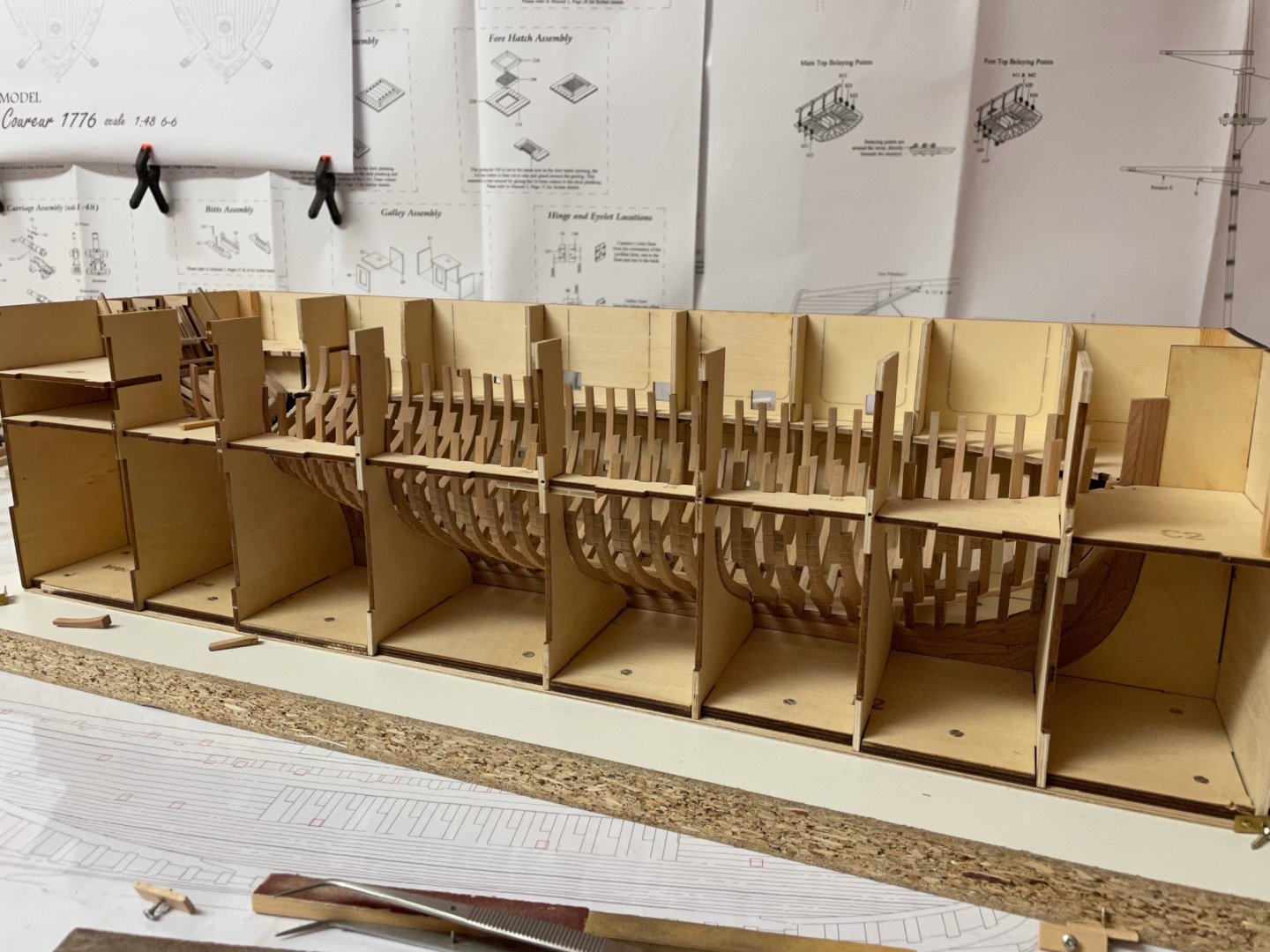
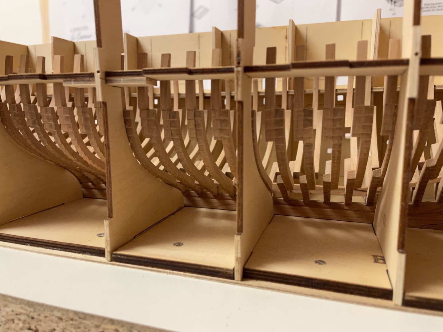
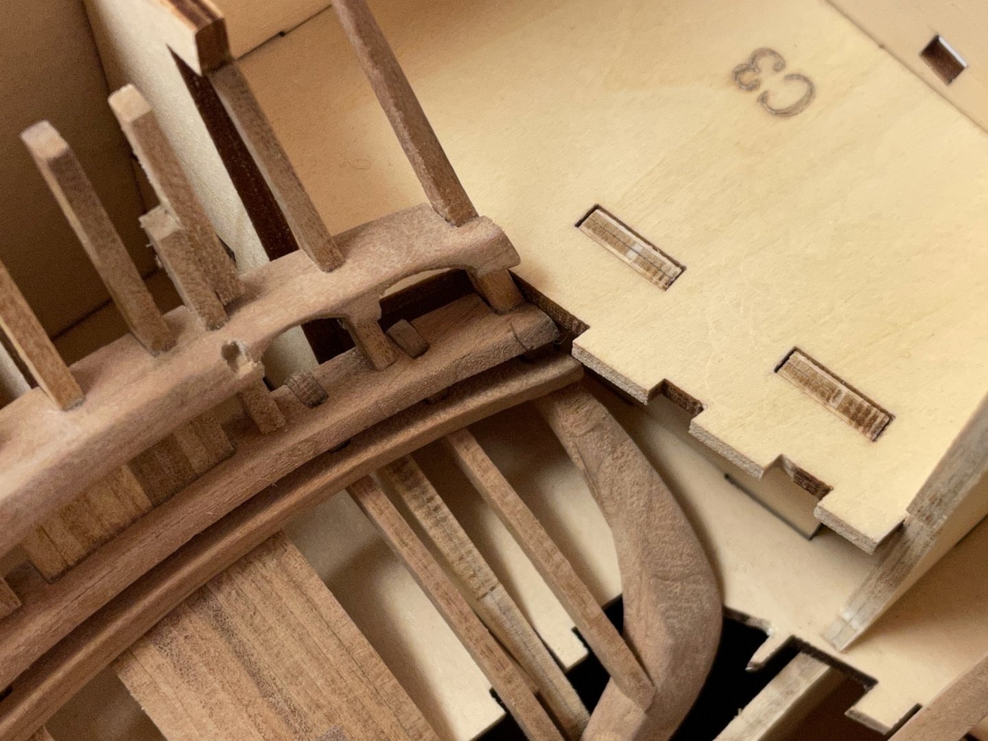
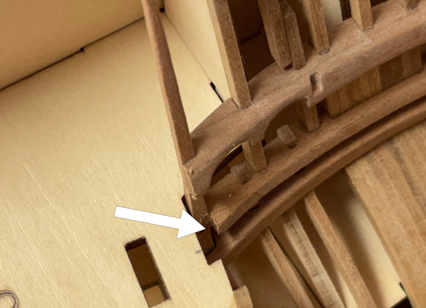
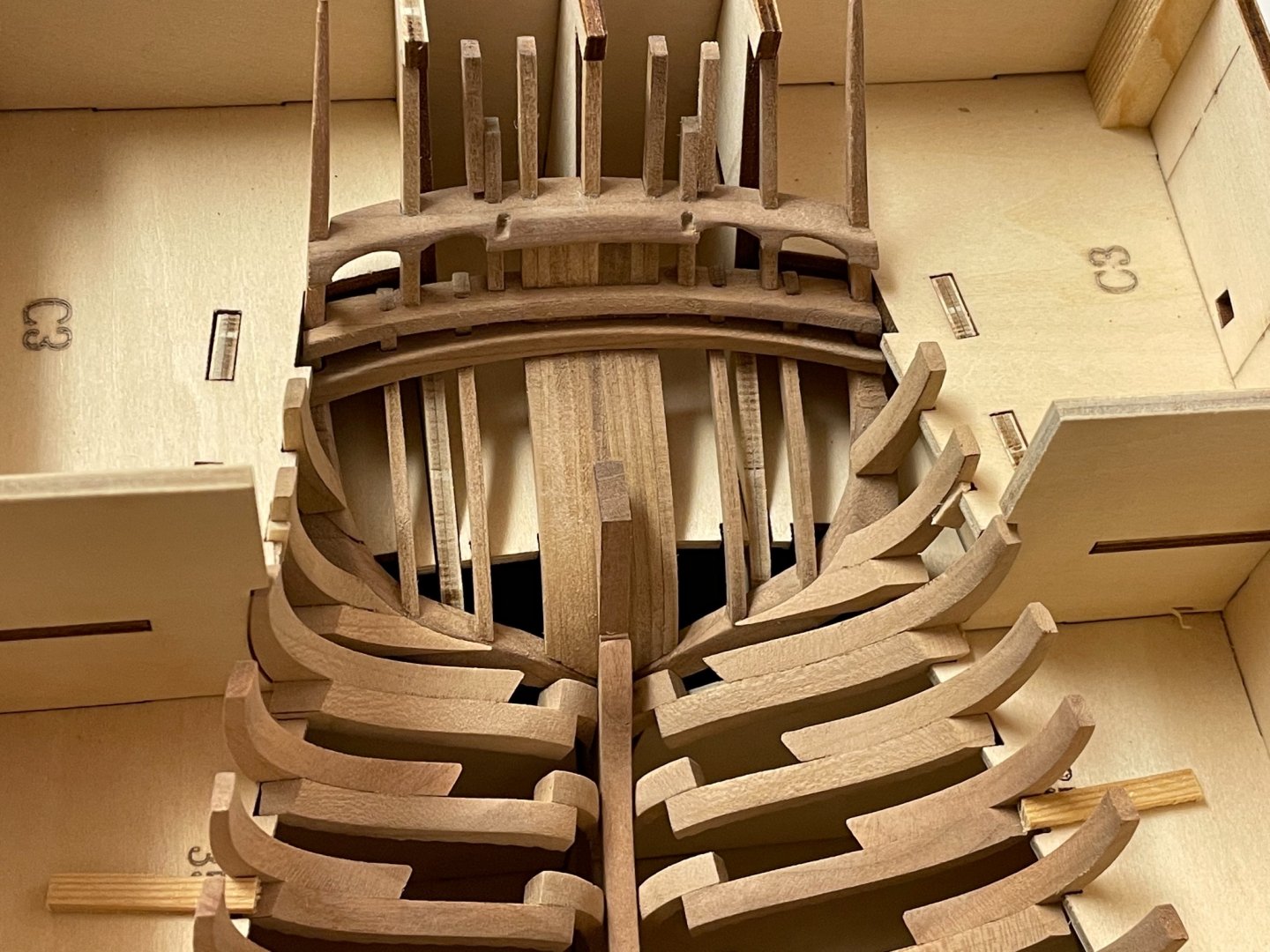
Today I finished all the deck clamps. The measuring sticks were helpful to locate the correct position and helped fixing the clamps during the gluing - although the lower stern clamps look a little weird. But the CAD-drawing provided by CAF show them in the same position and shape. Well I guess then it is the way it should be done. And the bow clamps as well. Next weekend I will start planking the inside of the hull. Just have to figure out where to start. Stay tuned and save. Andreas


-
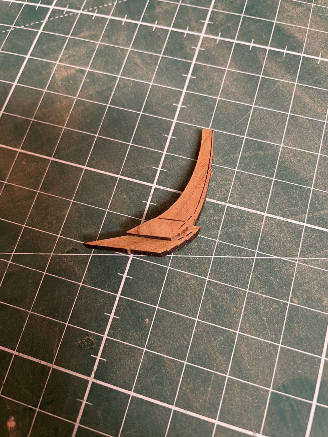
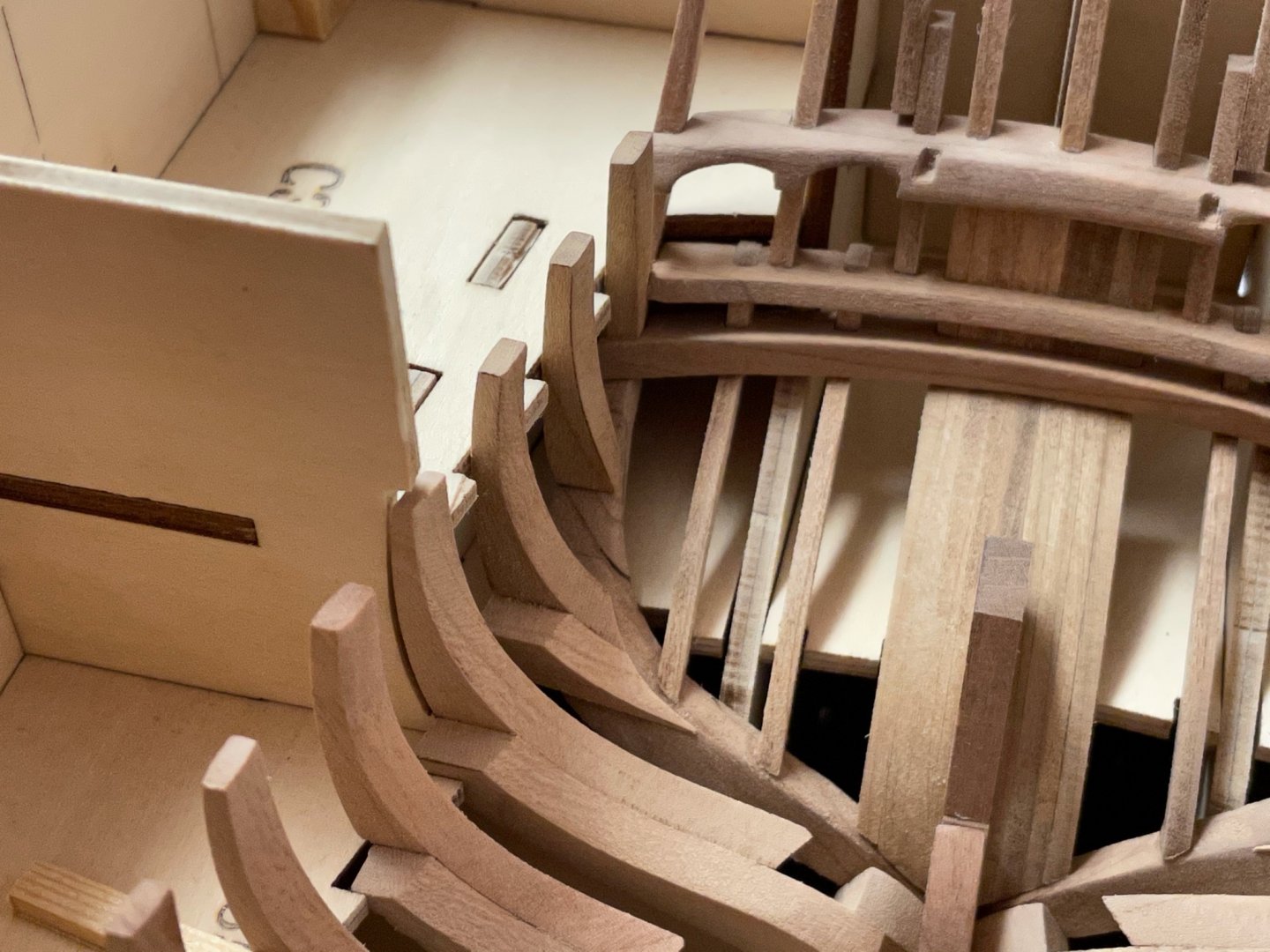
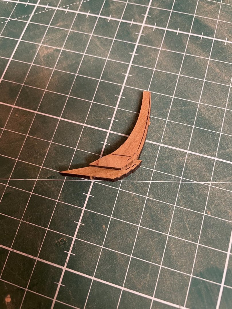
Thank you WalrusGuy! The installation of the deck clamps took a lot of time and patience and I haven‘t finished the task yet. The lower clamps are made of 3mm cherry wood and even watering them in hot water for about an hour made them little flexible. So I used some heat to bend them. Especially the stern part has to be bend into a complex shape. At least I was able to finish the bow and middle sections. Heavy clamps were of use to secure a good fit until the glue had dried. Only snapshots this time. I will finish this task next weekend. Stay tuned and save (some more time) ..

-
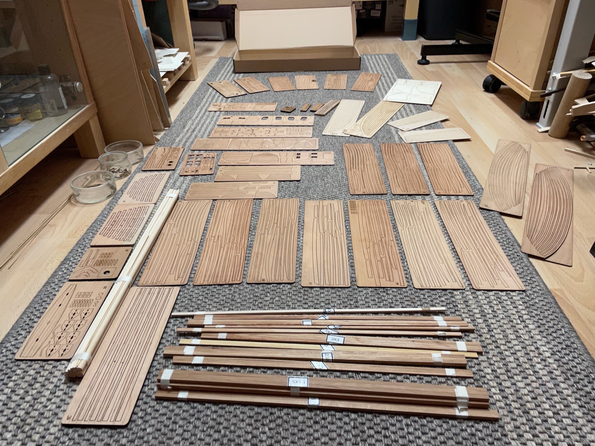
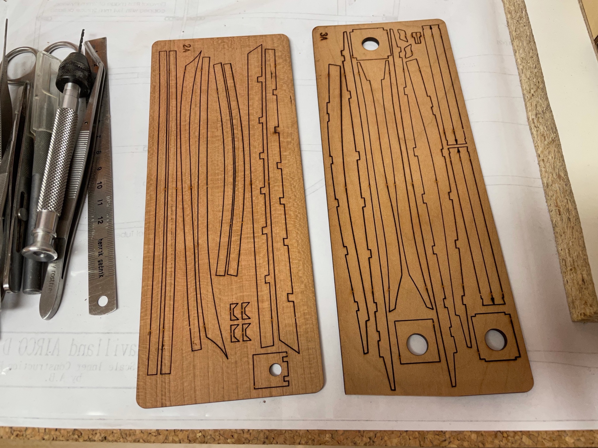
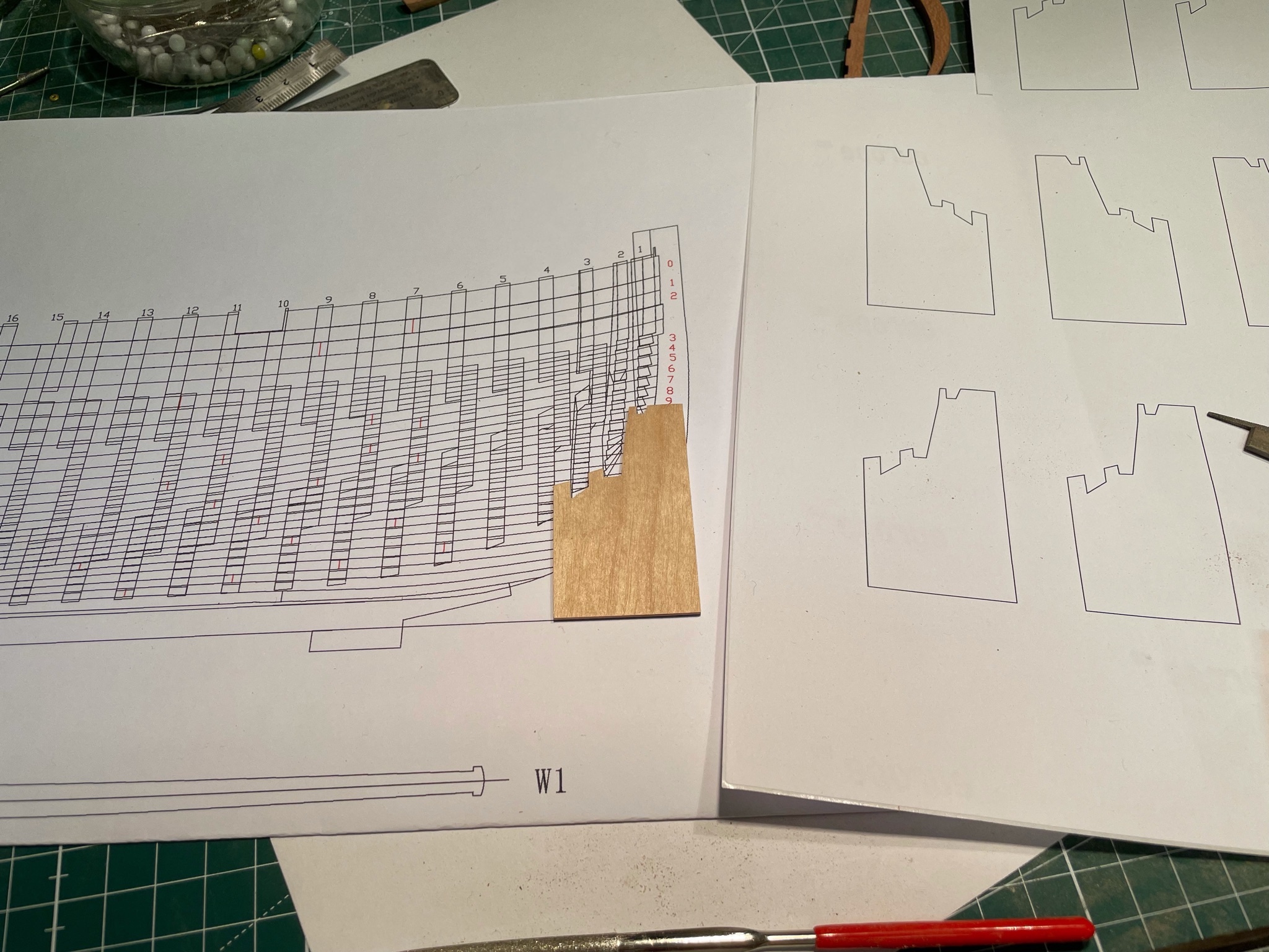
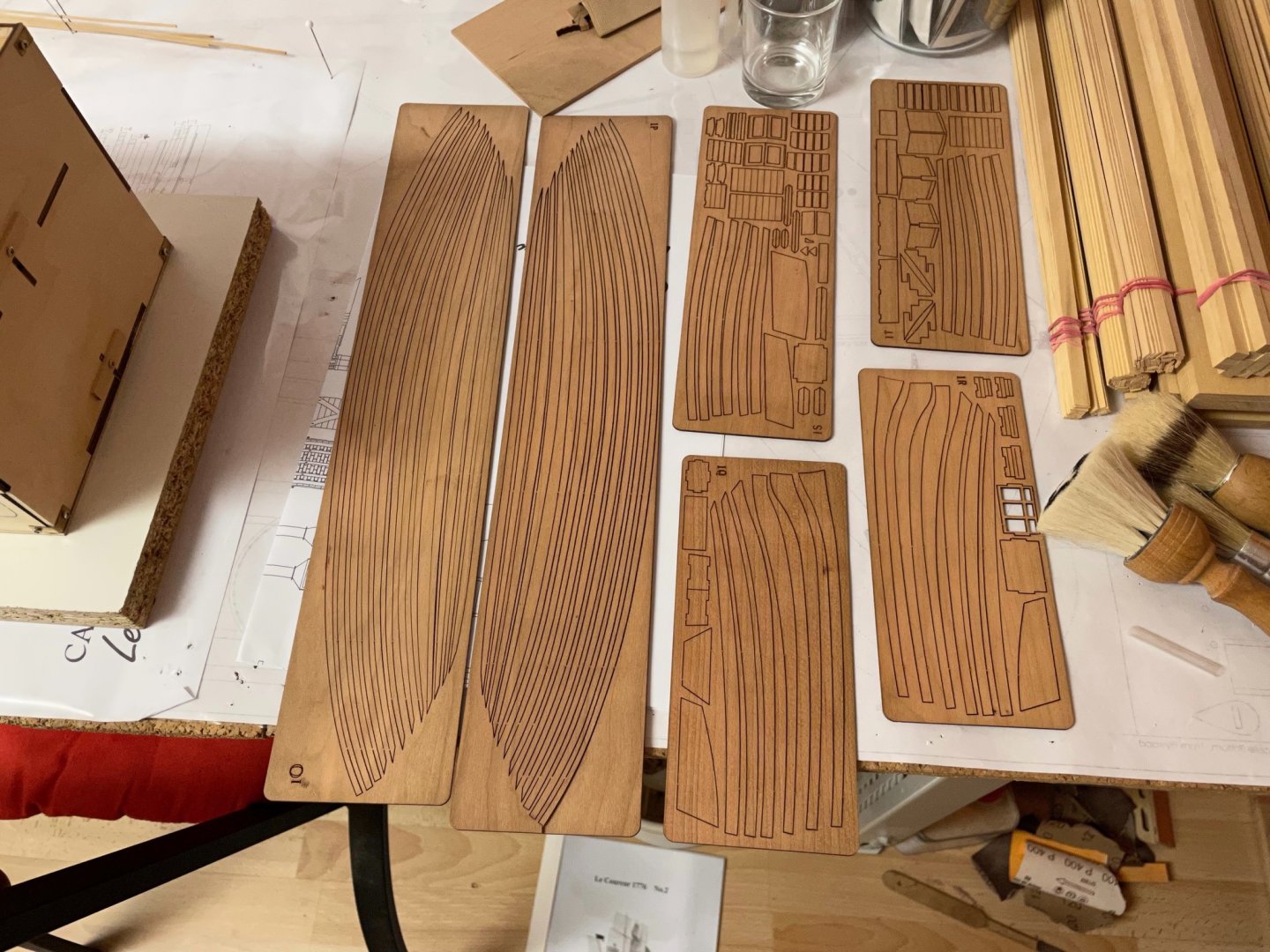
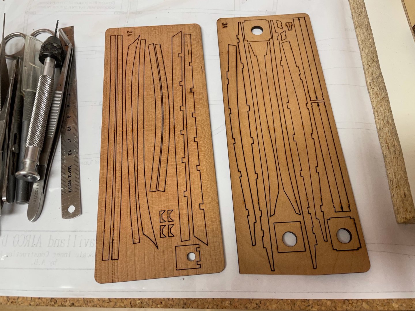
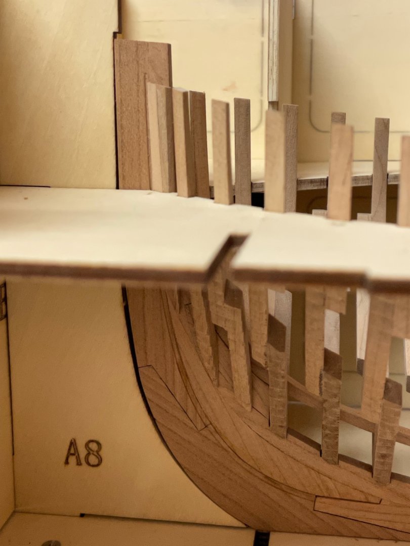
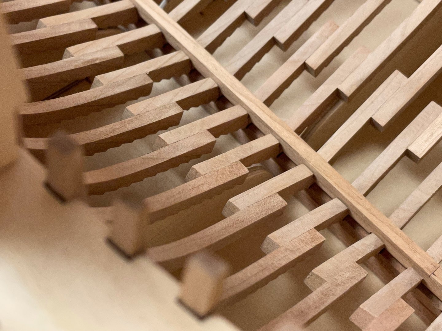
The second box contains all parts for the inner structure, planking the inside and outside of the ship, deck planking and fittings, masting, rigging as well as the metal and other small parts - in other words all the other stuff. There are lots of laser-cut cherry wood parts. OMG - looks like I won’t find much time for the Badger soon .. For planking the inside of the ship there are several sheets with laser-cut cherry planking supplied with the kit. These planks are already shaped to fit but some post-processing might be needed first - at least to get rid of the laser char. They are very thin and might easily break so forcing them into shape might not be a good idea. Maybe I’ll use some heat to bend them. But first I have to install the deck clamps that will carry the deck beams later. These are also laser-cut but need to cleaned first and bend to shape. There are four parts on every side. To determine the correct position of the deck clamps and for easier Installation there are several holes cut into the jig. These are meant to take up cherry strips that will act as a guide for the deck clamps. The deck clamps will be installed directly under these strips. Here is an example. I will start to install the deck clamps next weekend. Stay tuned and save. Andreas


-
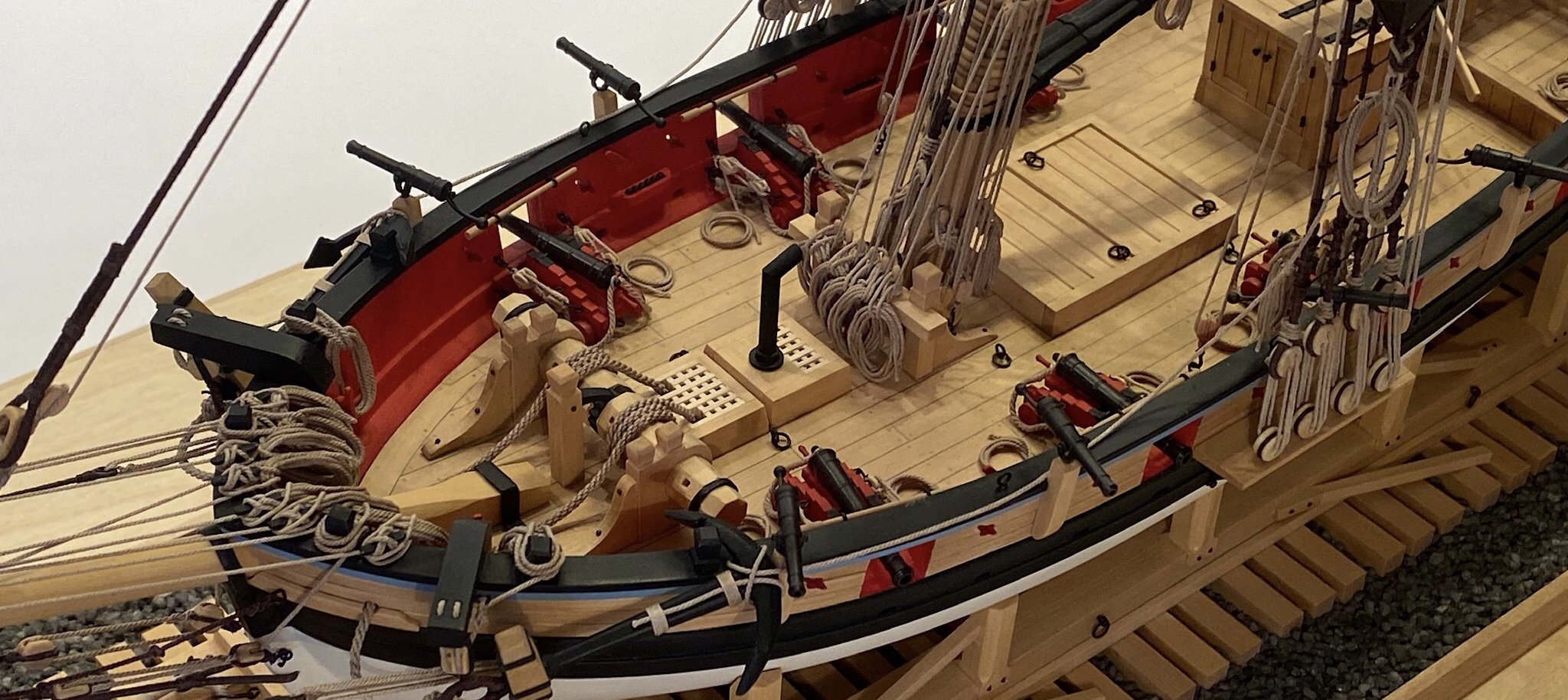
Congratulations! She is a beauty and you did a splendid job!
- 950 replies
-
- 2
-

-
-
- syren
- model shipways
- (and 1 more)
-
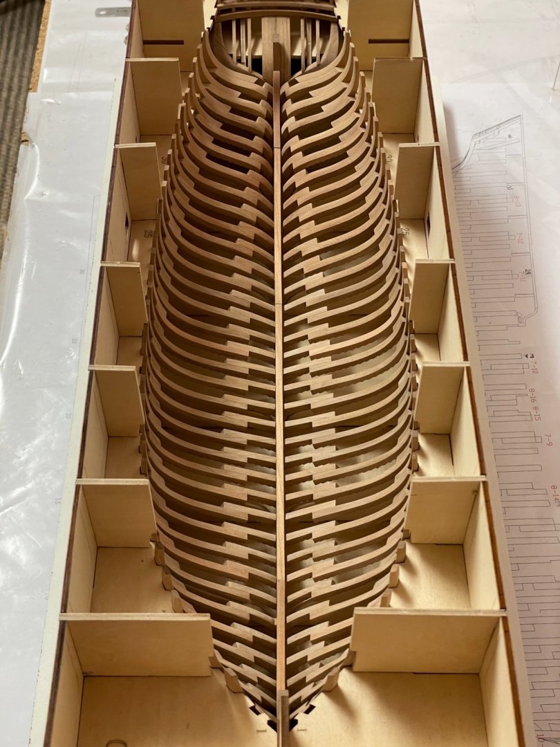
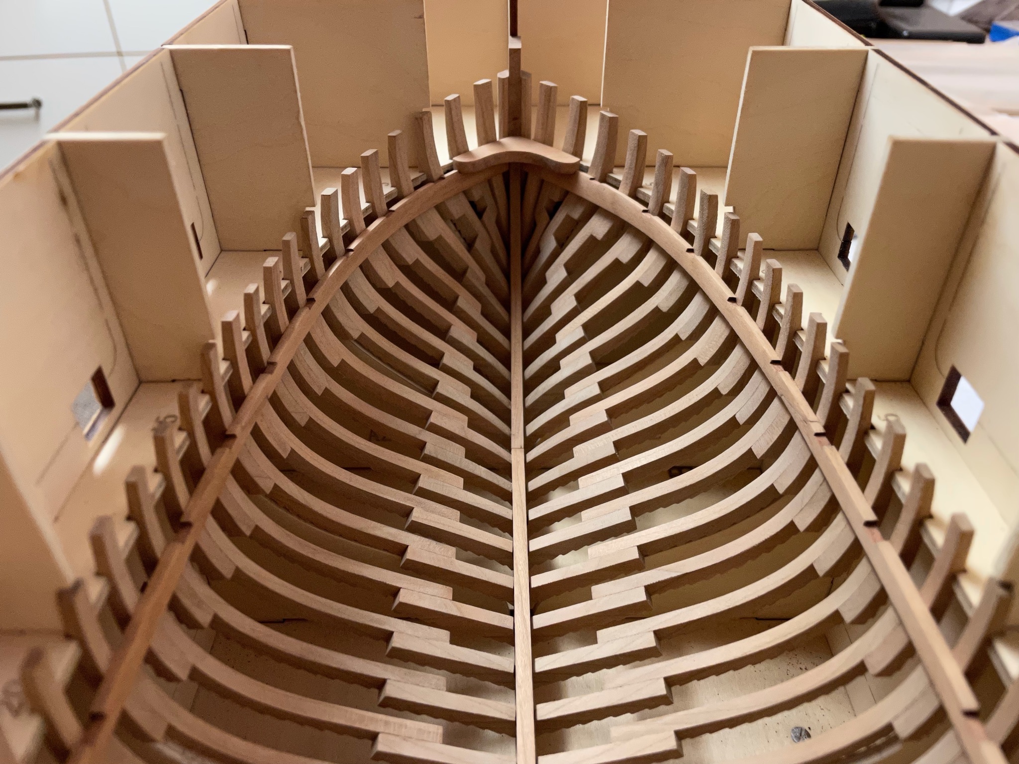
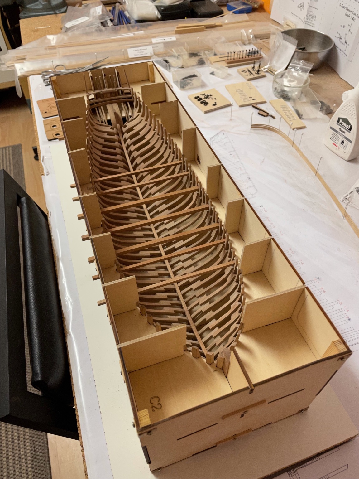
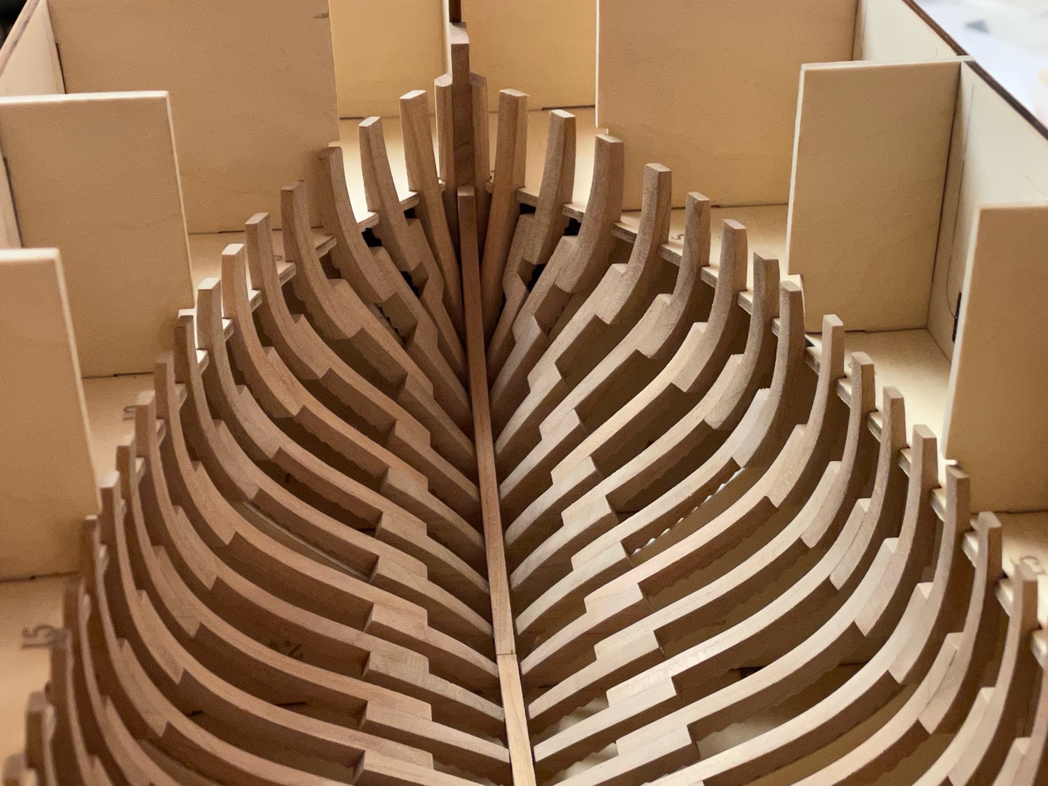
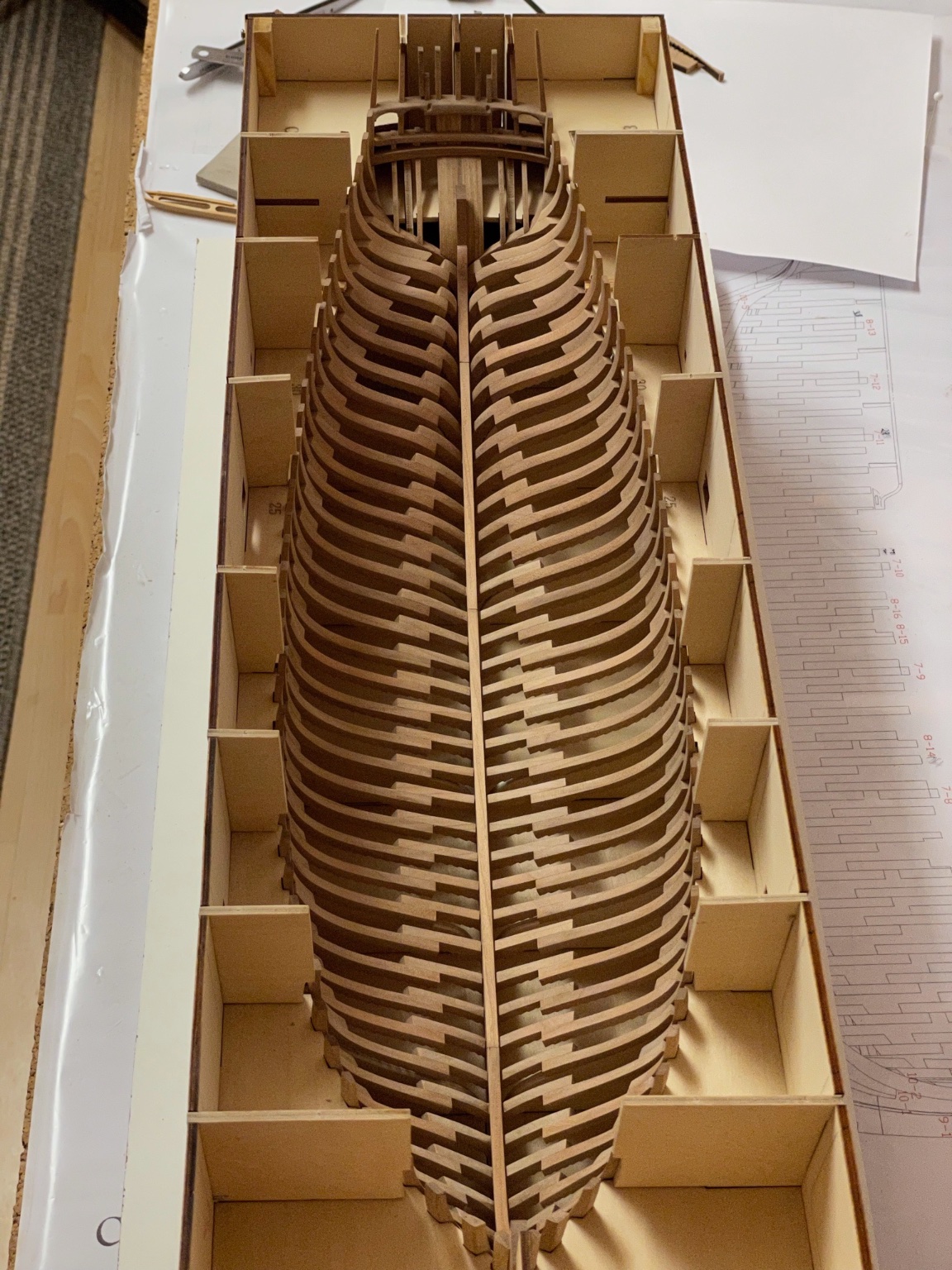
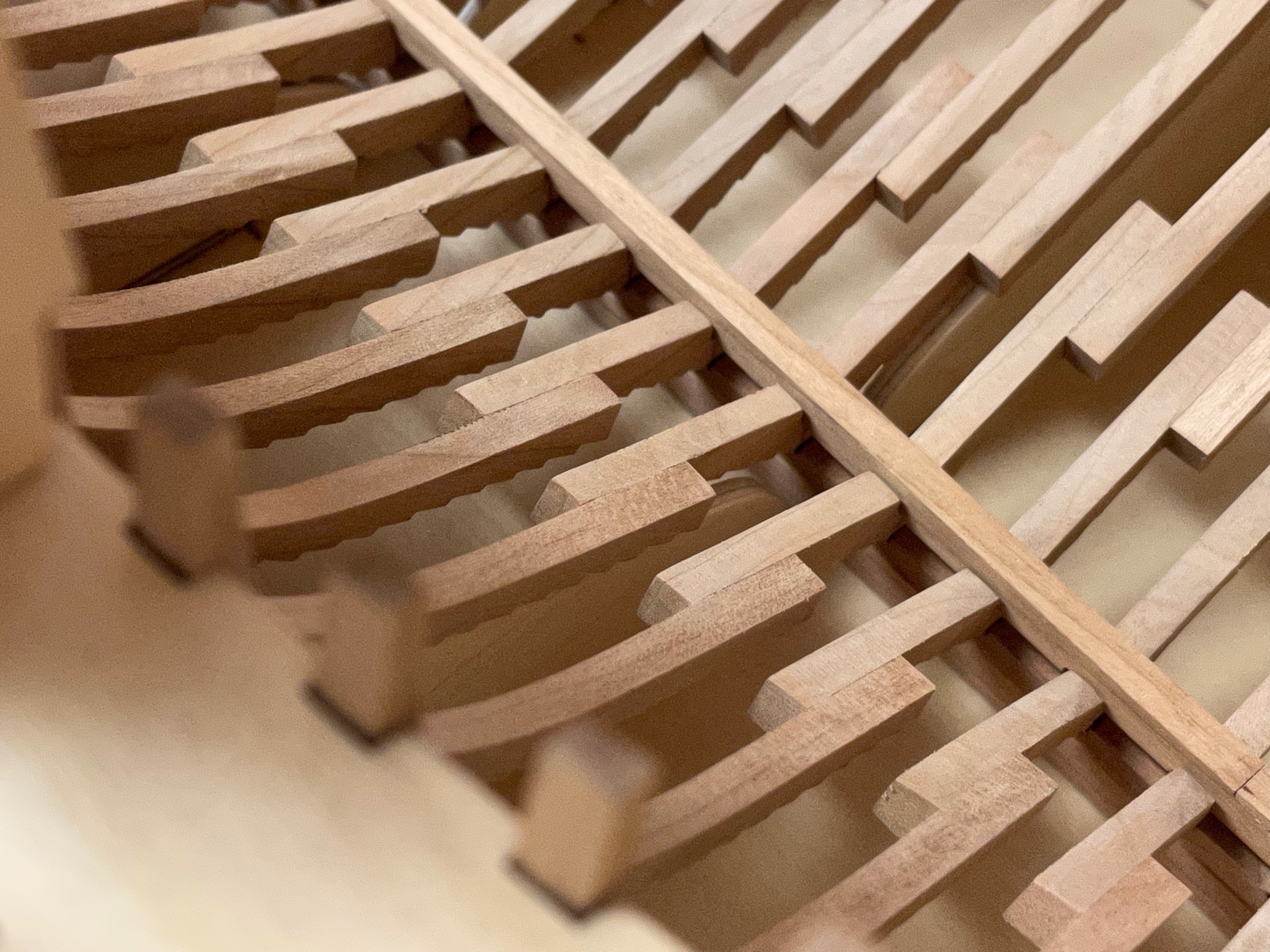
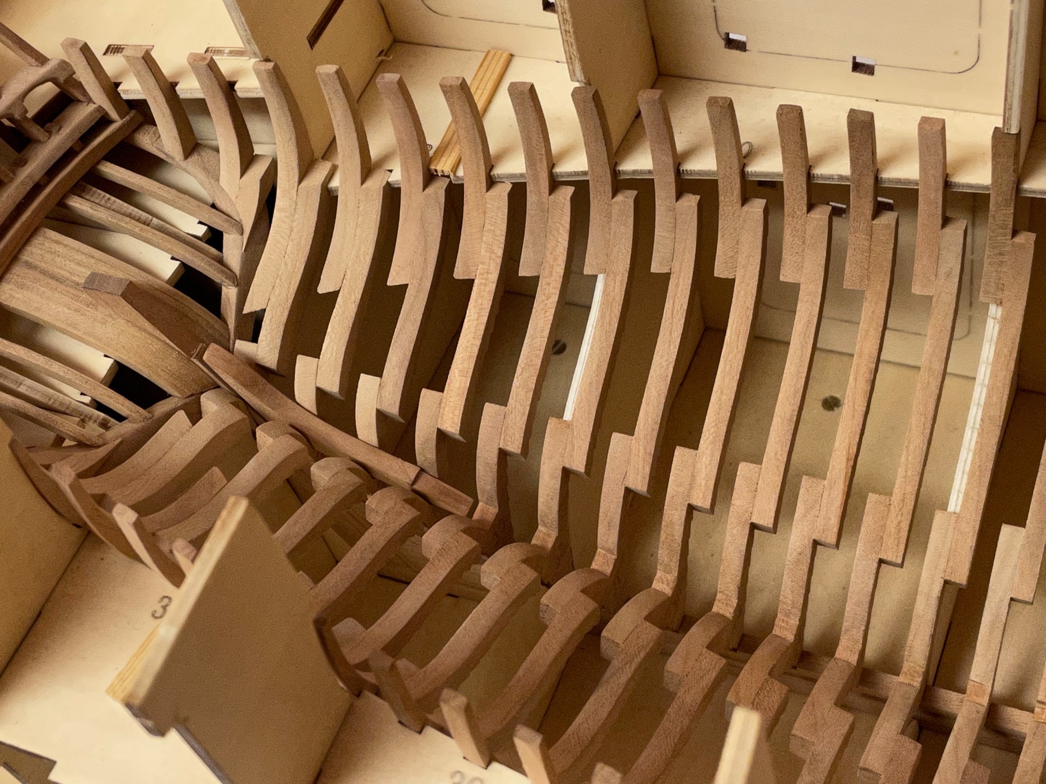
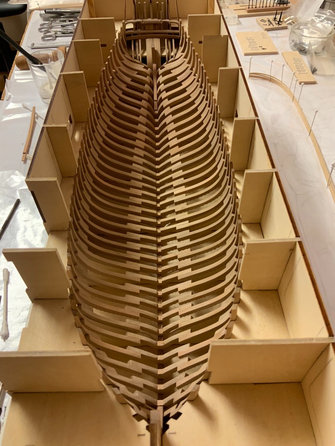
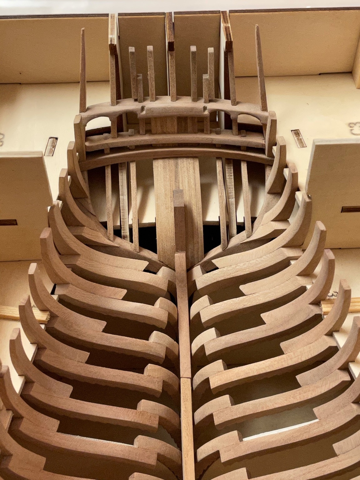
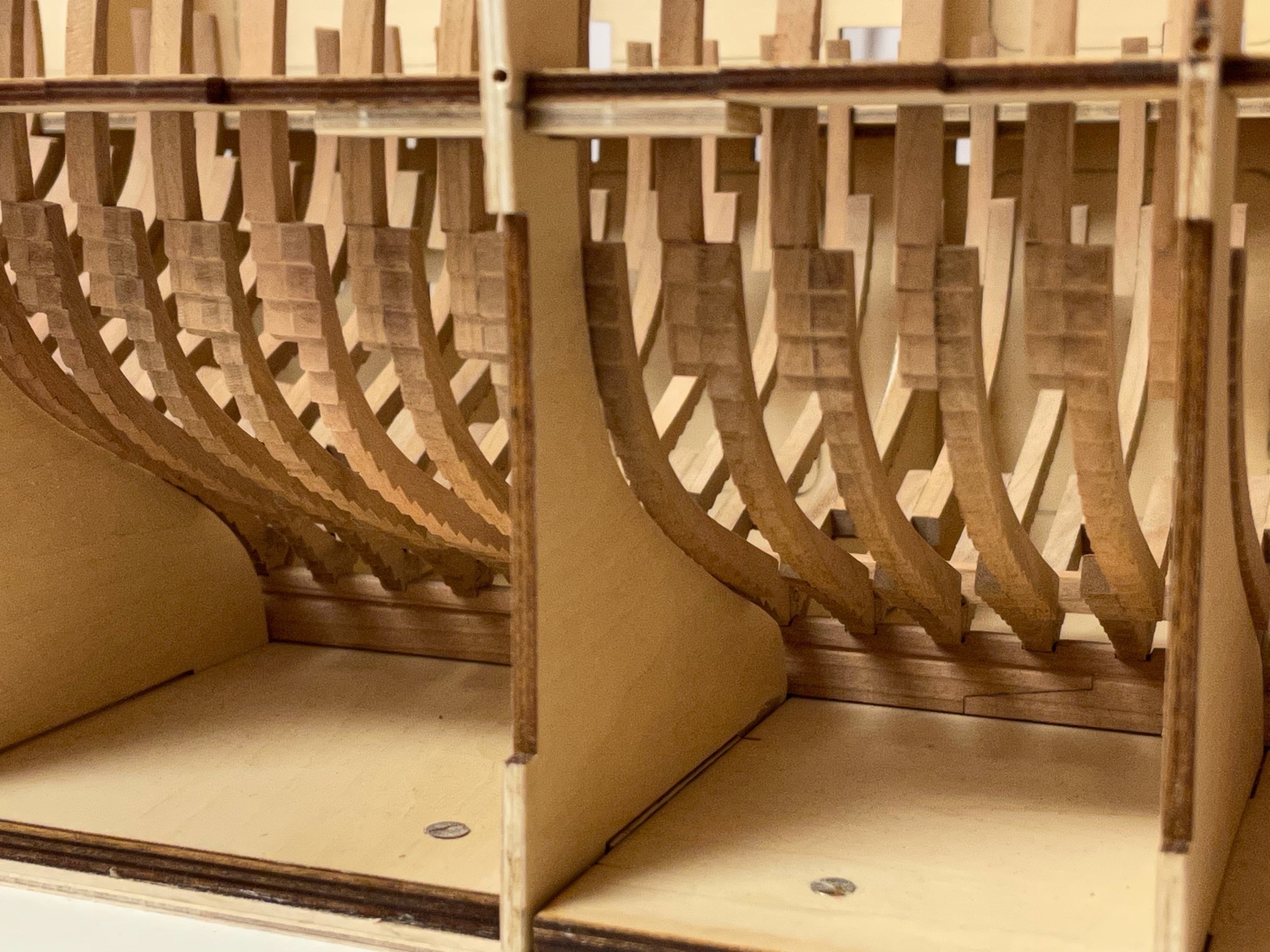
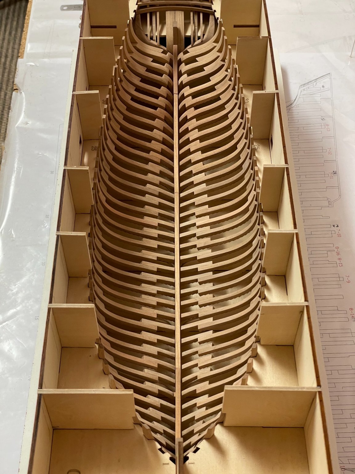
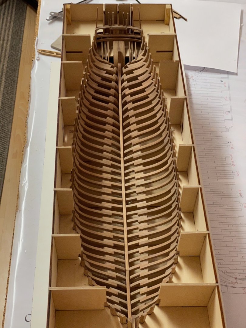
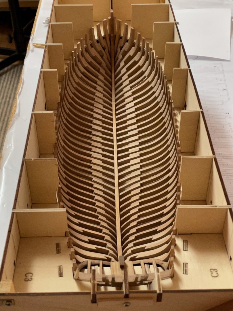
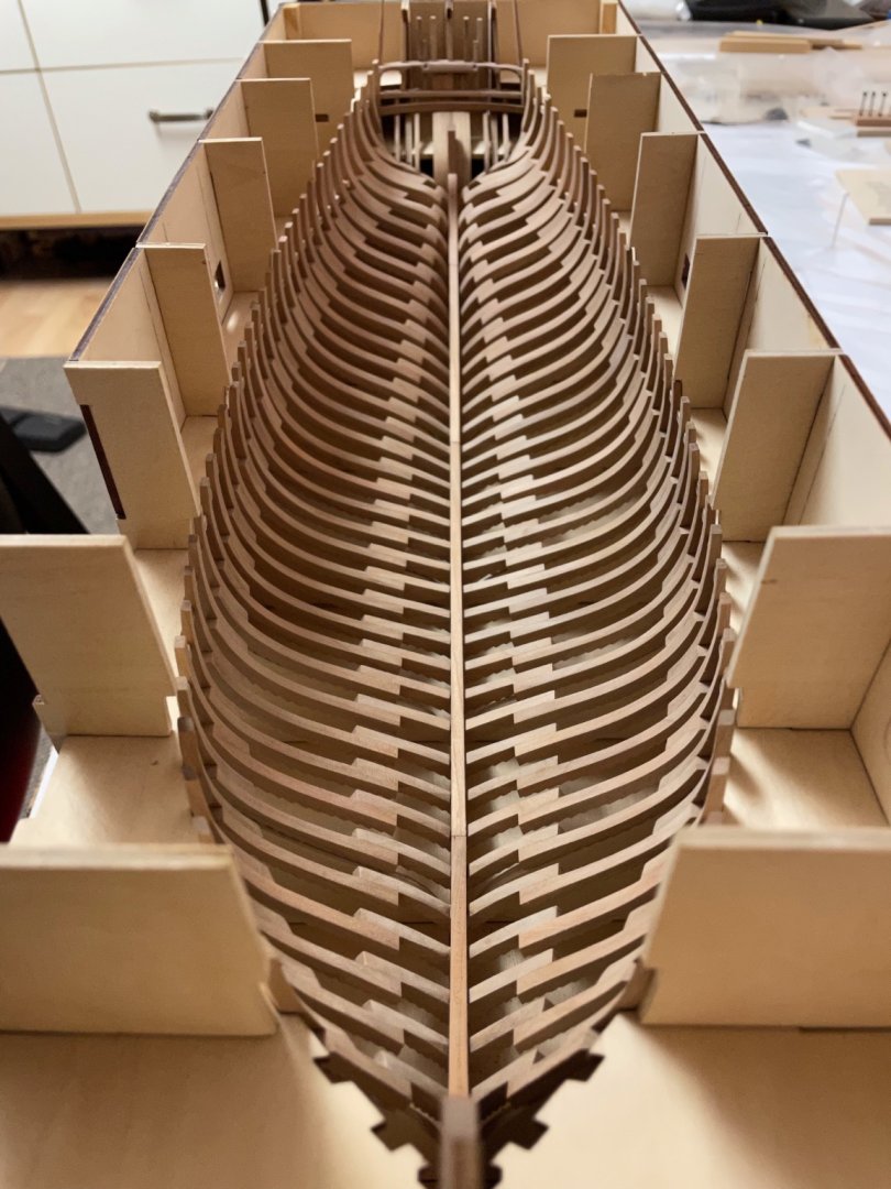
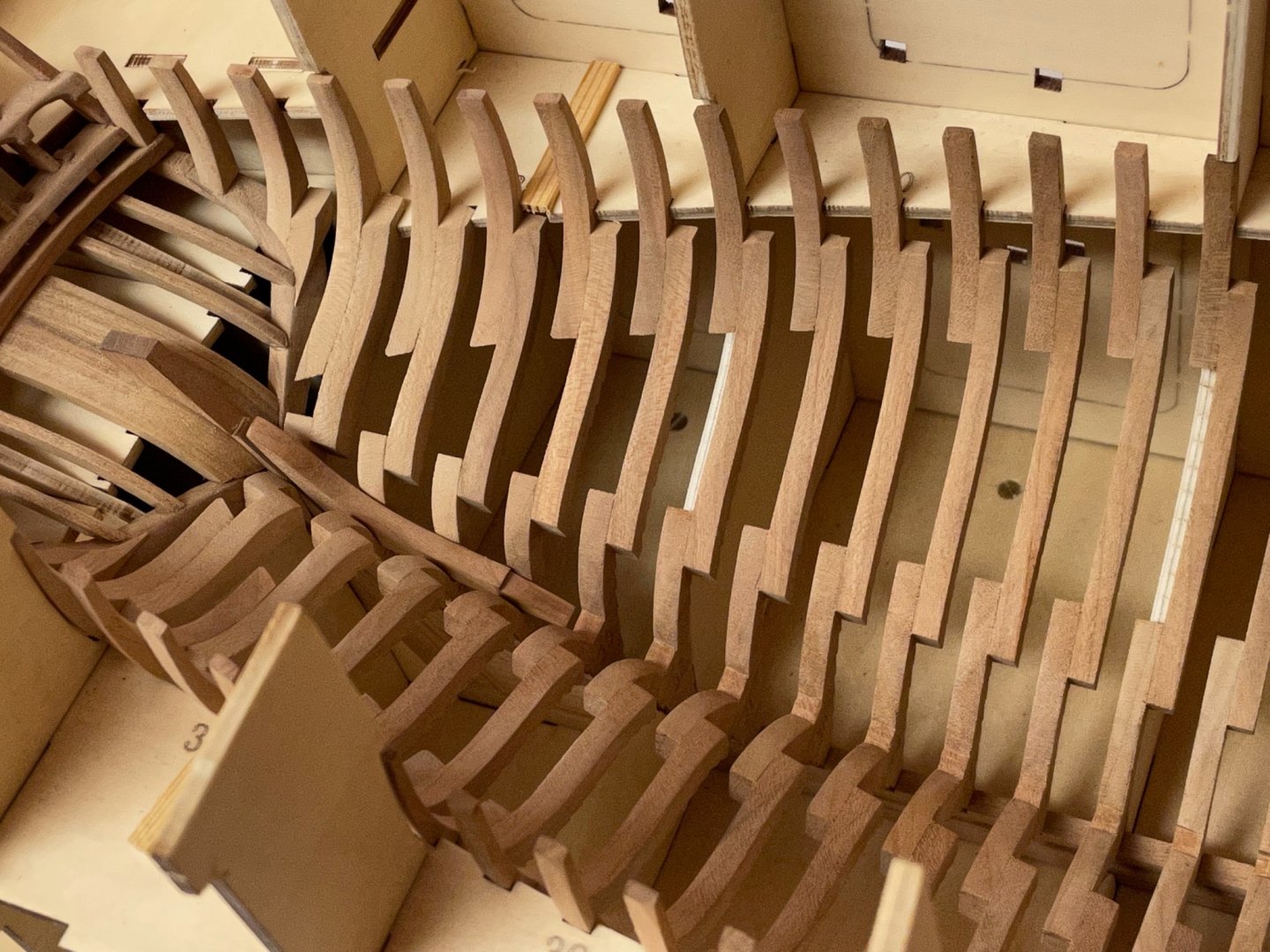
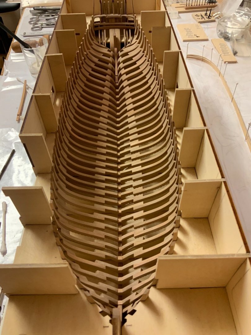
With the jig gluing the frames was rather easy, only to secure that corresponding frames were of equal shape and size. First I made a test-fit and then glued all of them in place. After glue has dried the jig can be removed. After doing this on both sides, the building jig was reassembled again. That finishes the first installation / box. Next will be planking the inner side, I will give a sneak peak inside the box within the next days. Some final shots of the finished framework. BTW I realized that I am a rather slow builder. Well .. Stay tuned and save .. Andreas


-
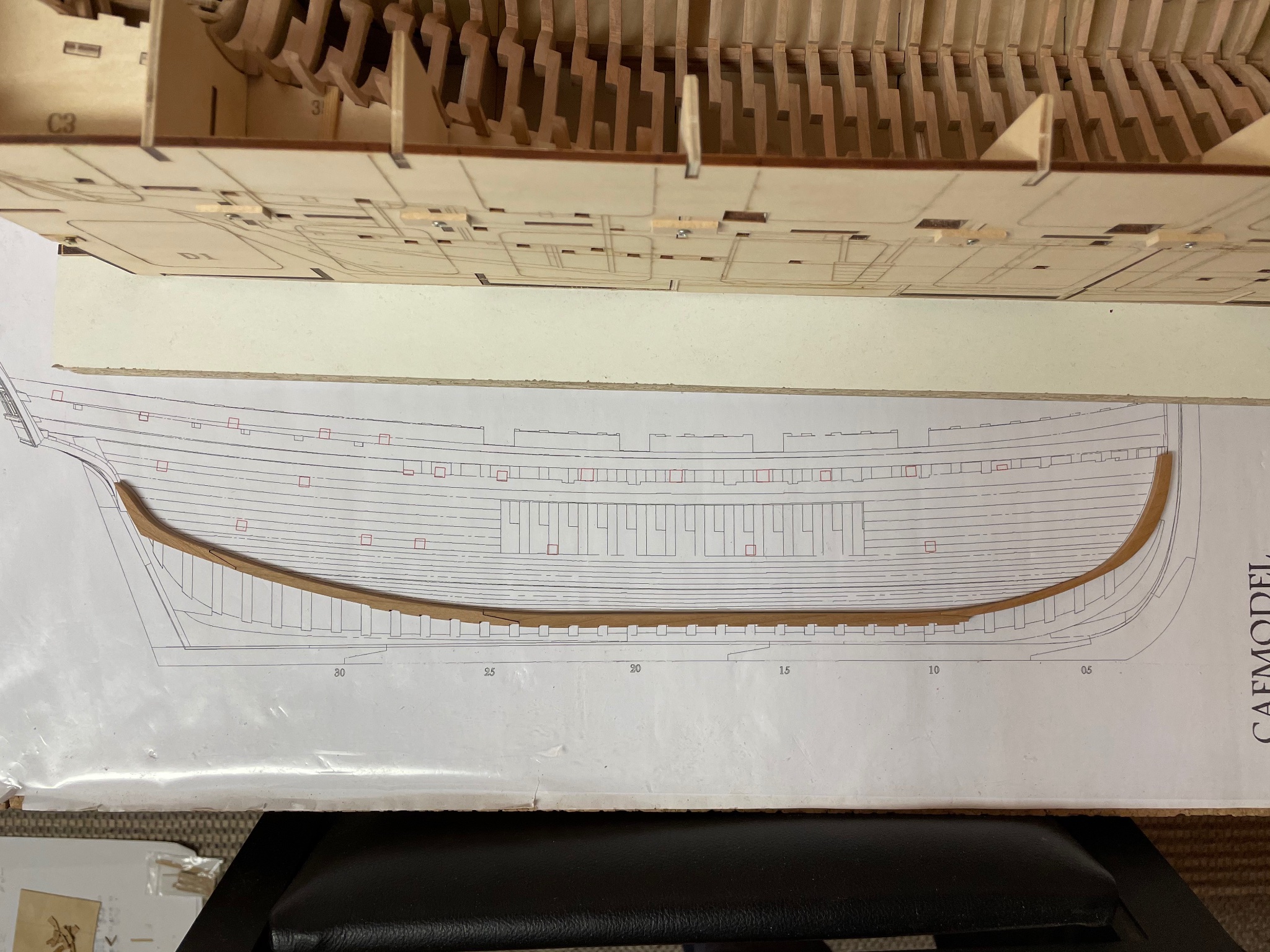
The cant frames are just glued onto the keel. But their position and tilt differ from frame 1 to 3. I thought about using different scrap wood parts to ensure correct alignment but the better solution turned out to be another jig. So I used the frames plan, scanned the segment and drew a jig with Corel. Printed that on adhesive paper and made a jig out of 1,5mm plywood. Test fit for frames - passed. For better view and handling I removed the side door and the side panel, they‘re only fixed by screws. Hope that will secure equal position of all frames when they are glued in ... in the next hour.


-
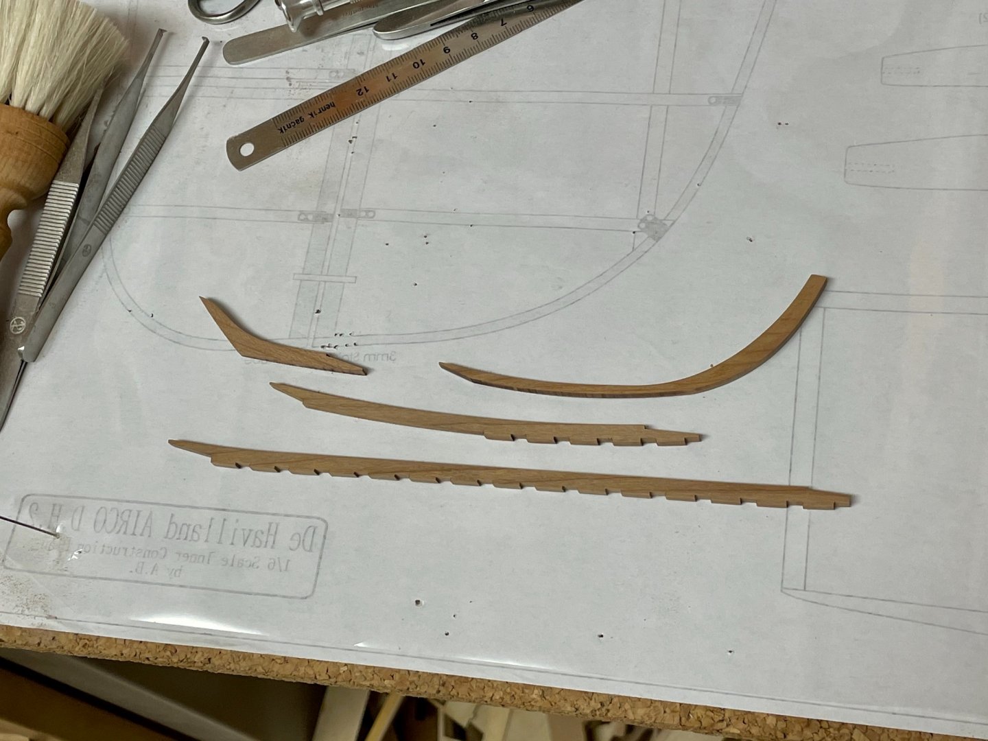
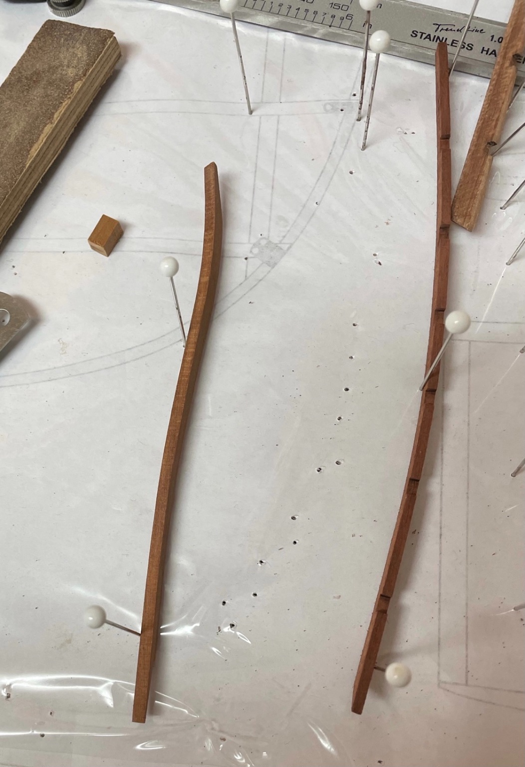
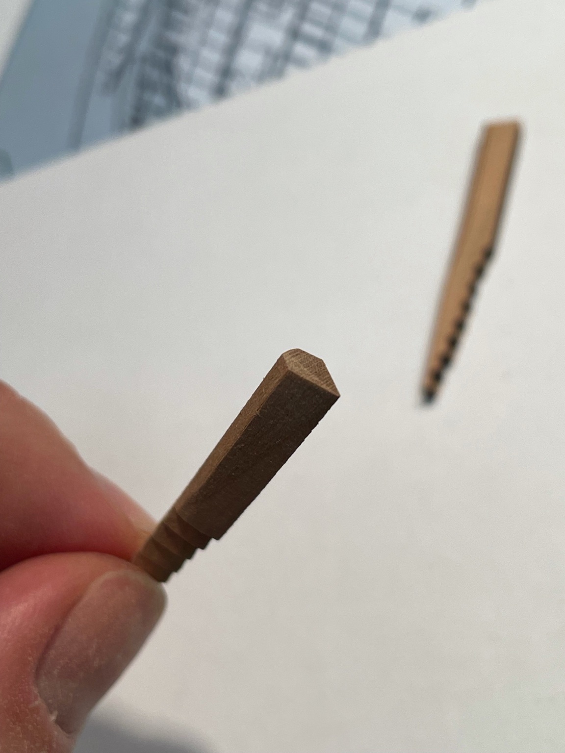
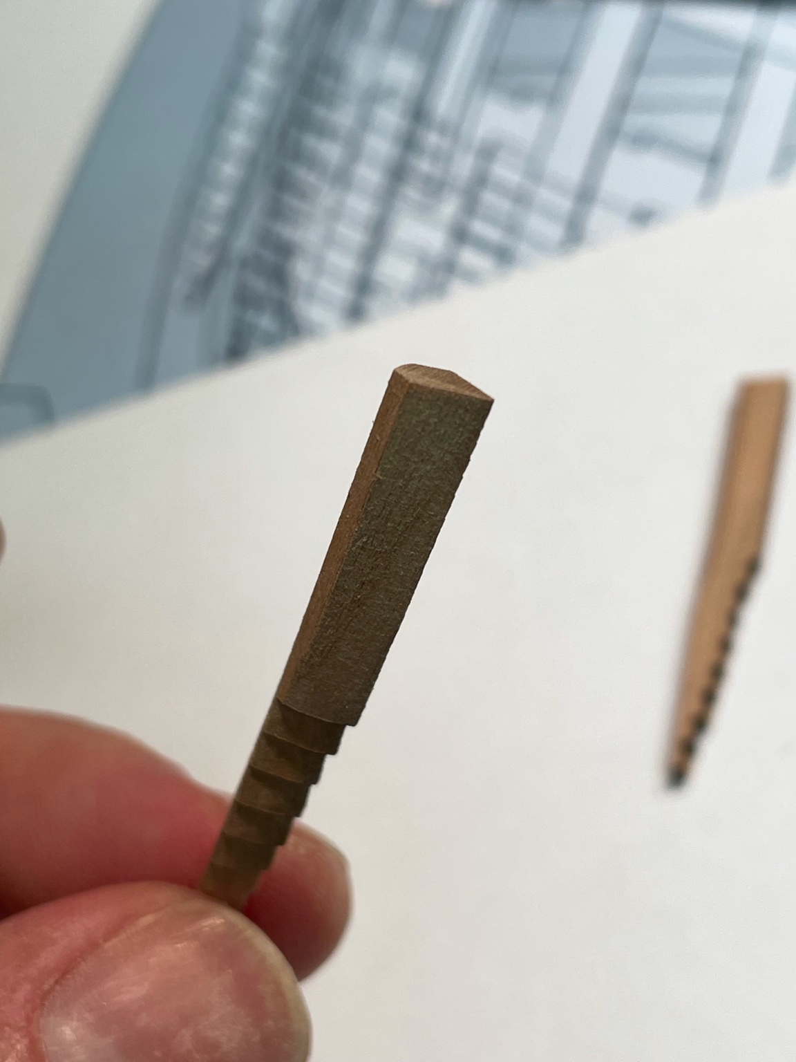
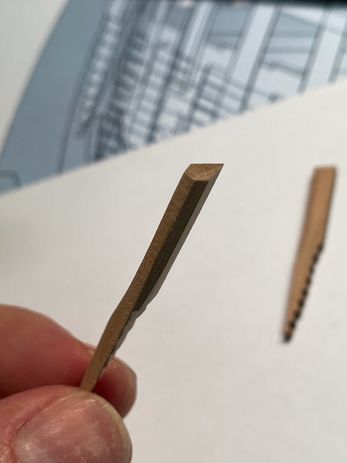
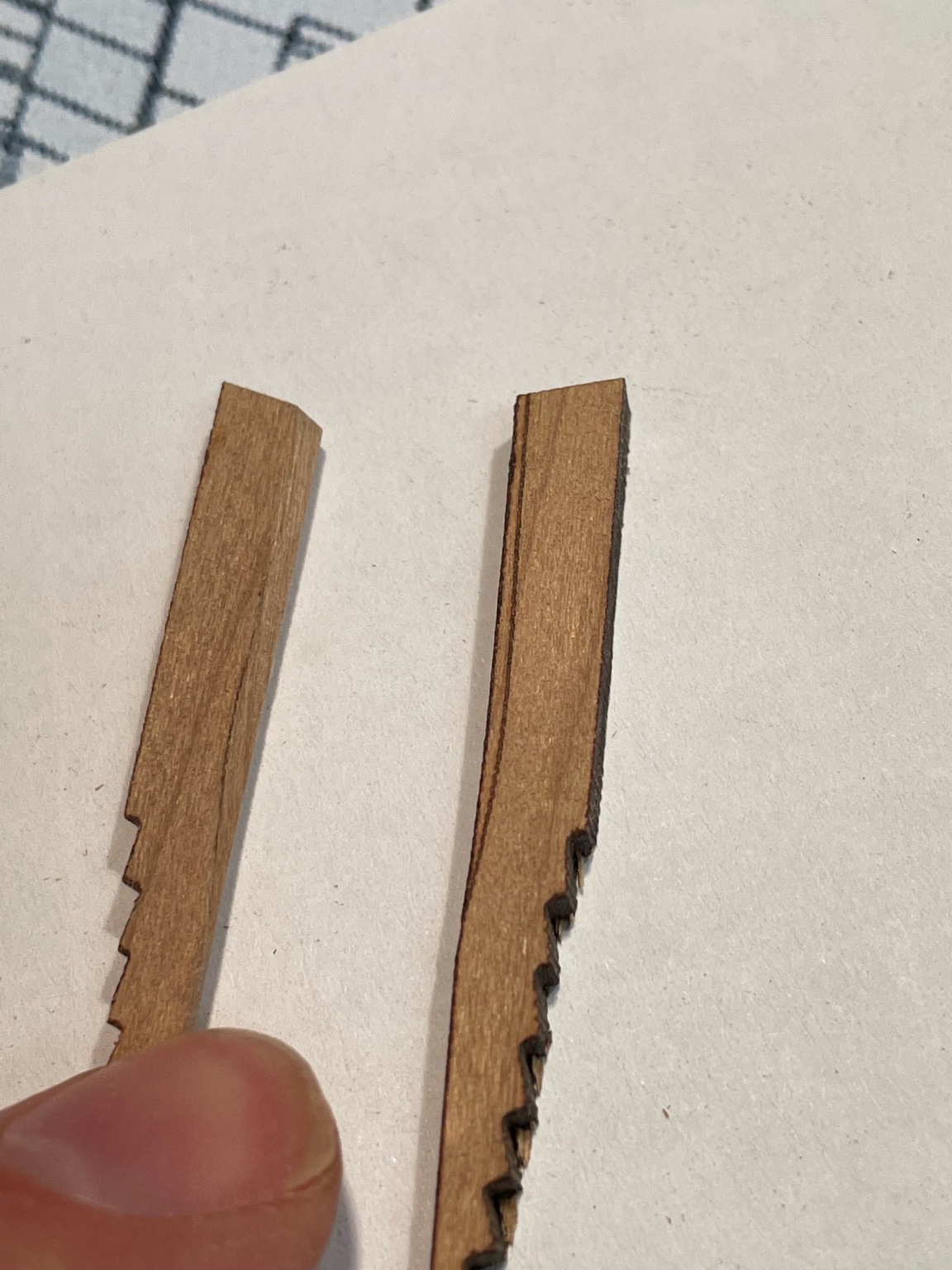
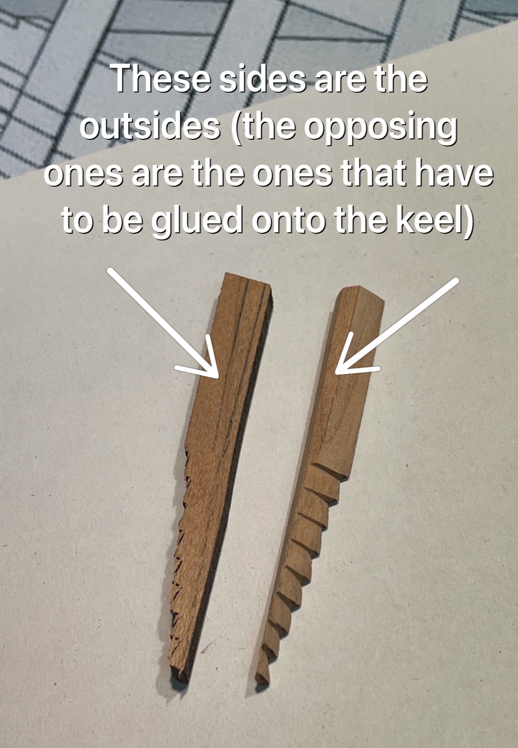
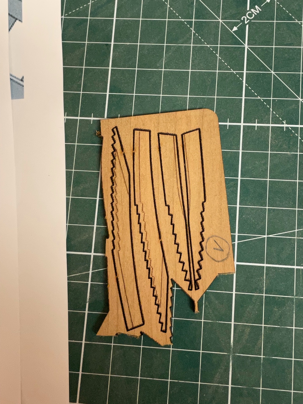
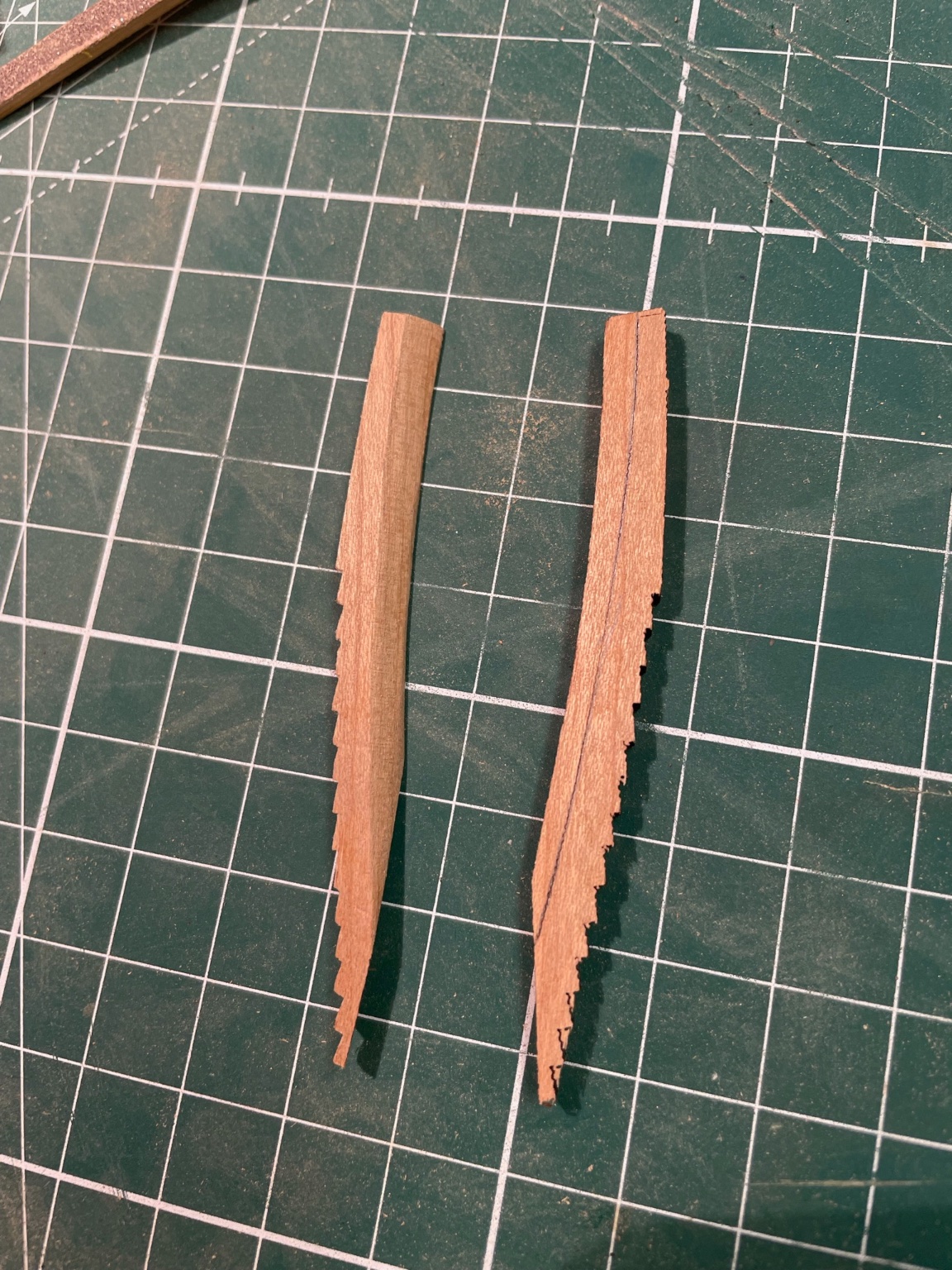
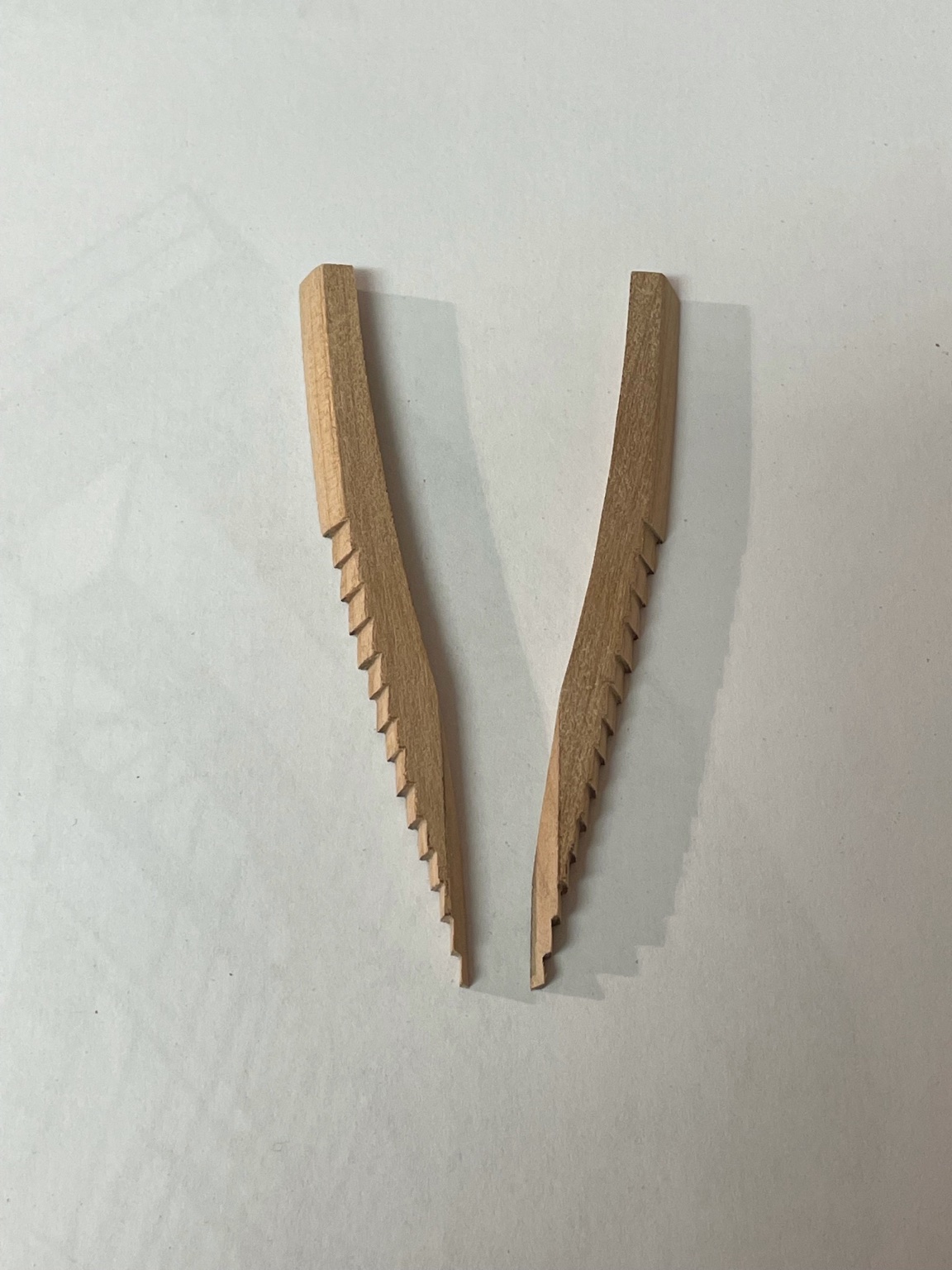
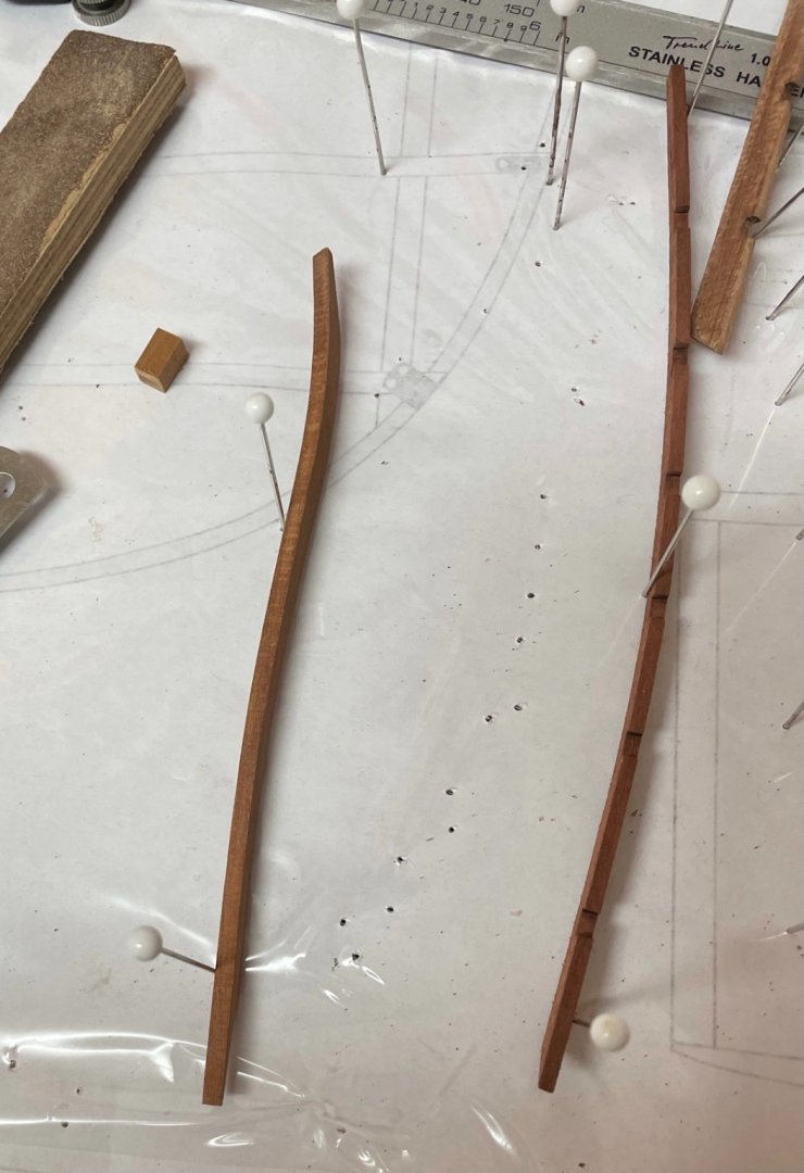
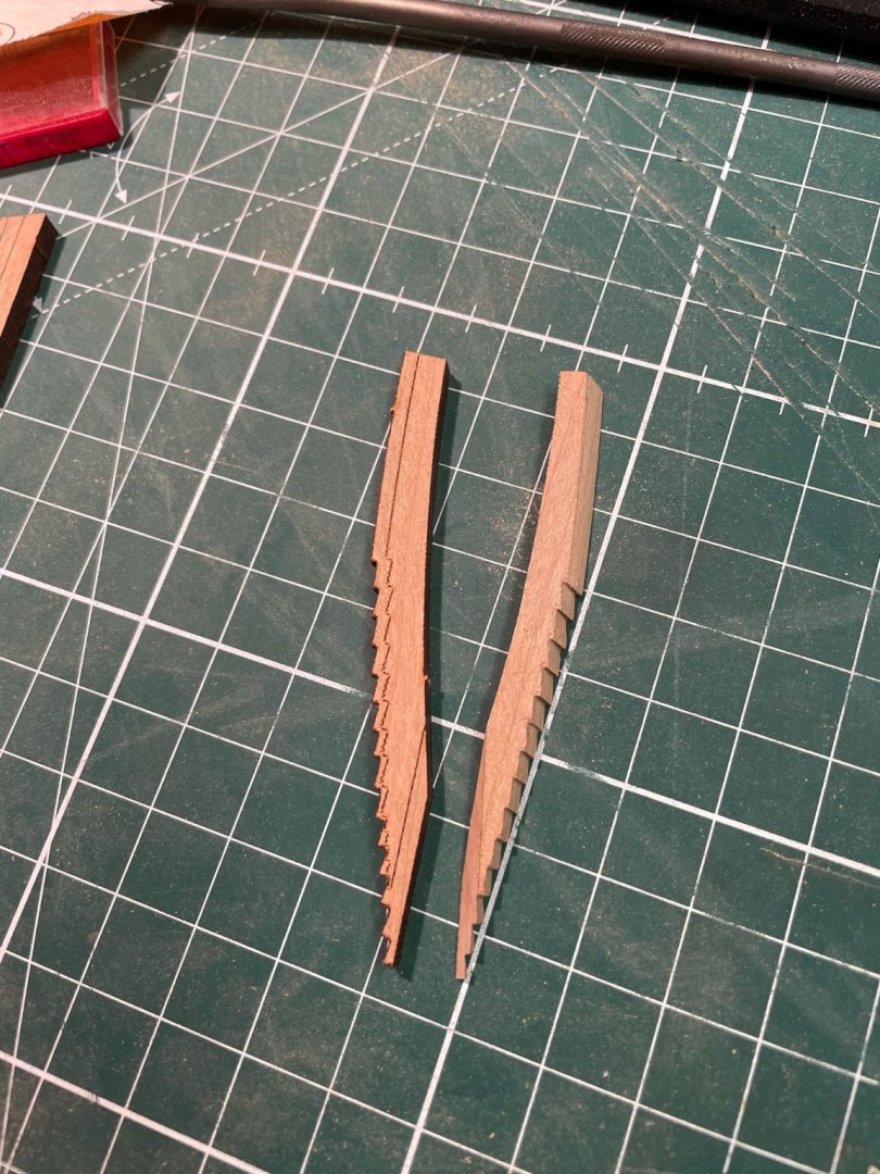
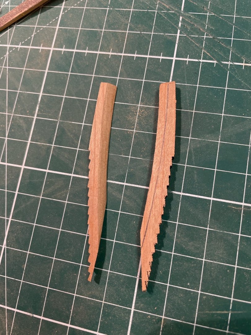
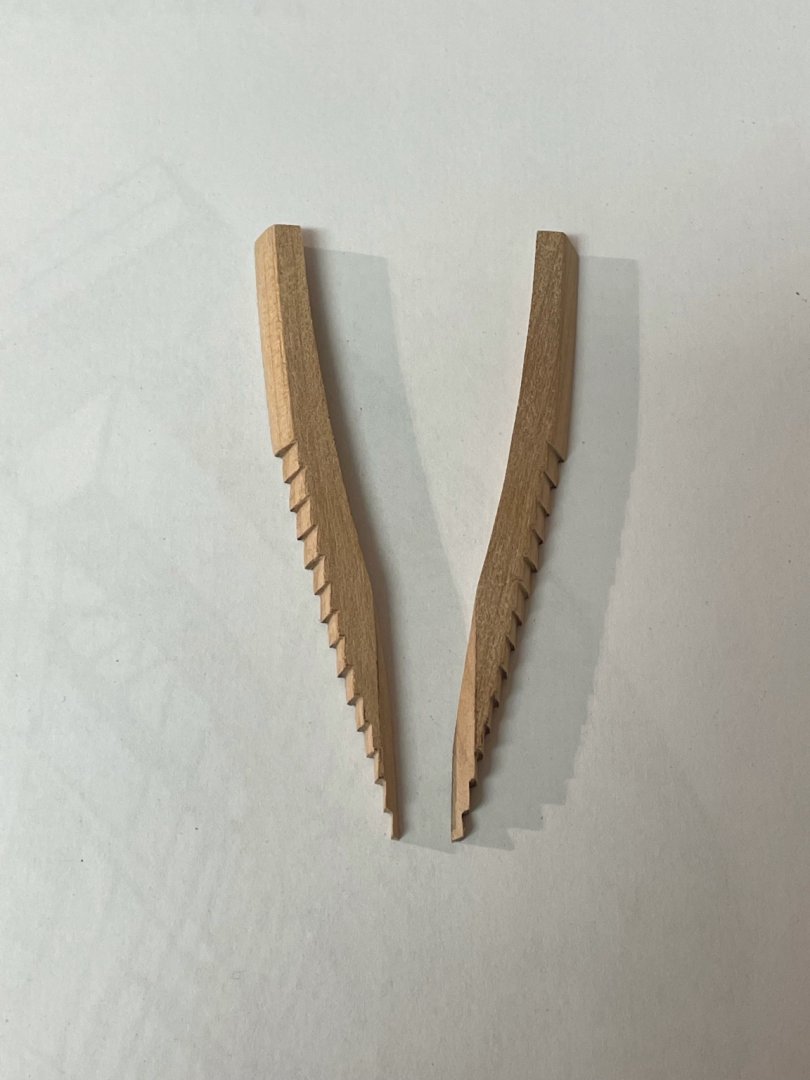
No. 1 is the tricky one. You have to determine first which side has to be attached to the keel and then taper them using the engraved lines as a guide. These are the sides to be glued on later. The rear tapering differs from the other ones. Each side has to be tapered to the center. Here are some pictures to get an idea. Here you can see the tapering from both sides goes straight to the center. Tomorrow I will give them a final sanding and then glue all of them in place. Stay tuned and save. Andreas


-
The last frames are just single pieces glued onto the side of the keel. Frame no. 2 (cant frame) requires some tapering on almost all sides. The other side as well. I will show no. 1 as well but have to recover from second covid vaccination first. Stay tuned and save..

-
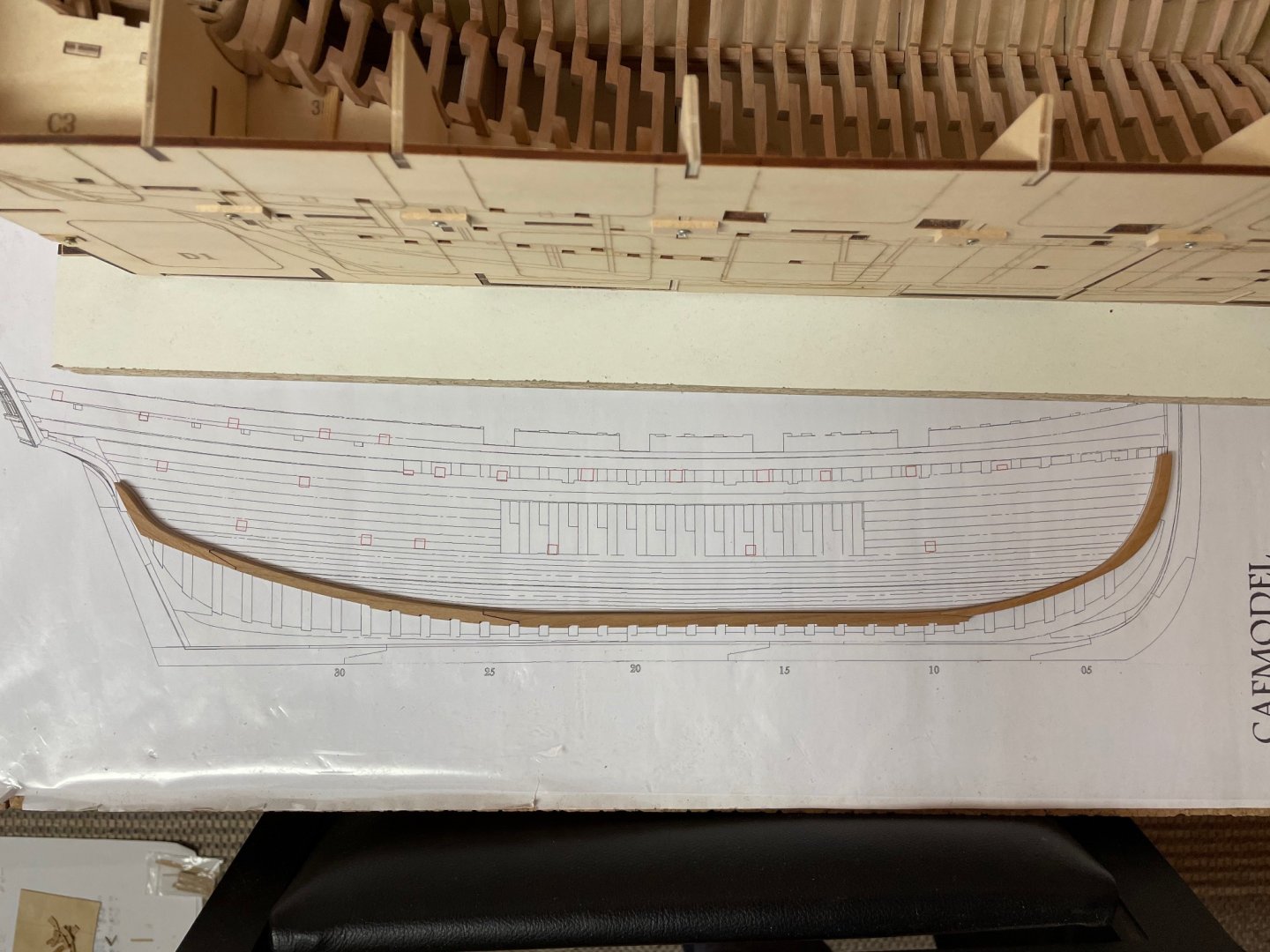
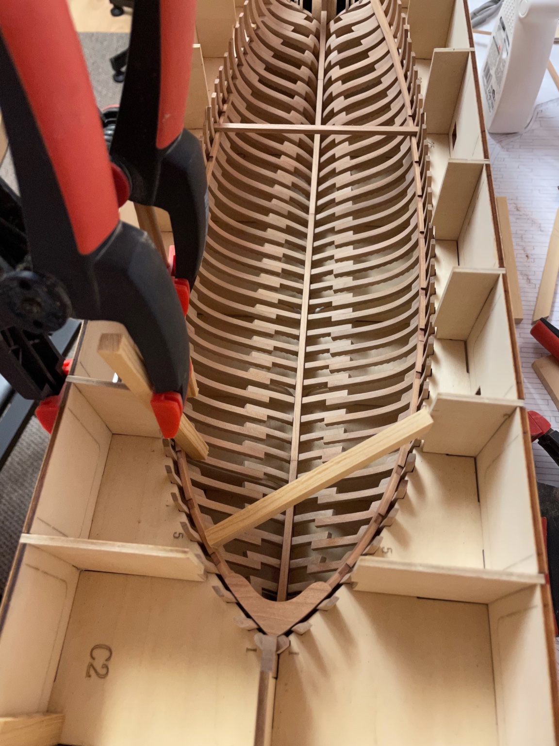
Thank you guys for the nice comments! Installation of the keelson was more time-consuming than expected. It is made of four segments. I first glued the stern part in - followed by the next part until the keelson was build up. I recommend dry-fitting each part several times until a nice fit is secured. Unfortunately it is difficult to catch with my camera .. The last step of the first box will be the cant frames. Stay tuned and save.. Andreas

-
Like this one?

-
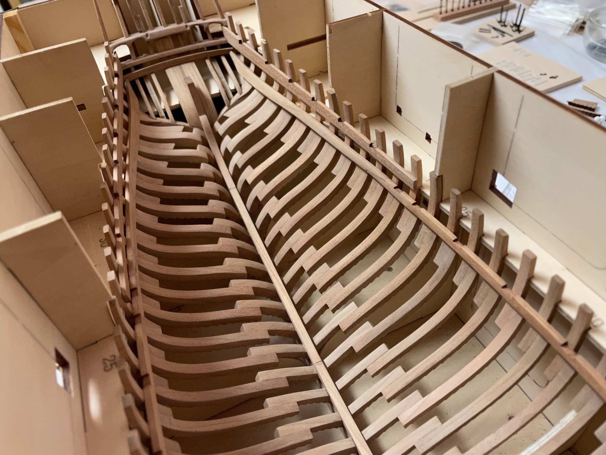
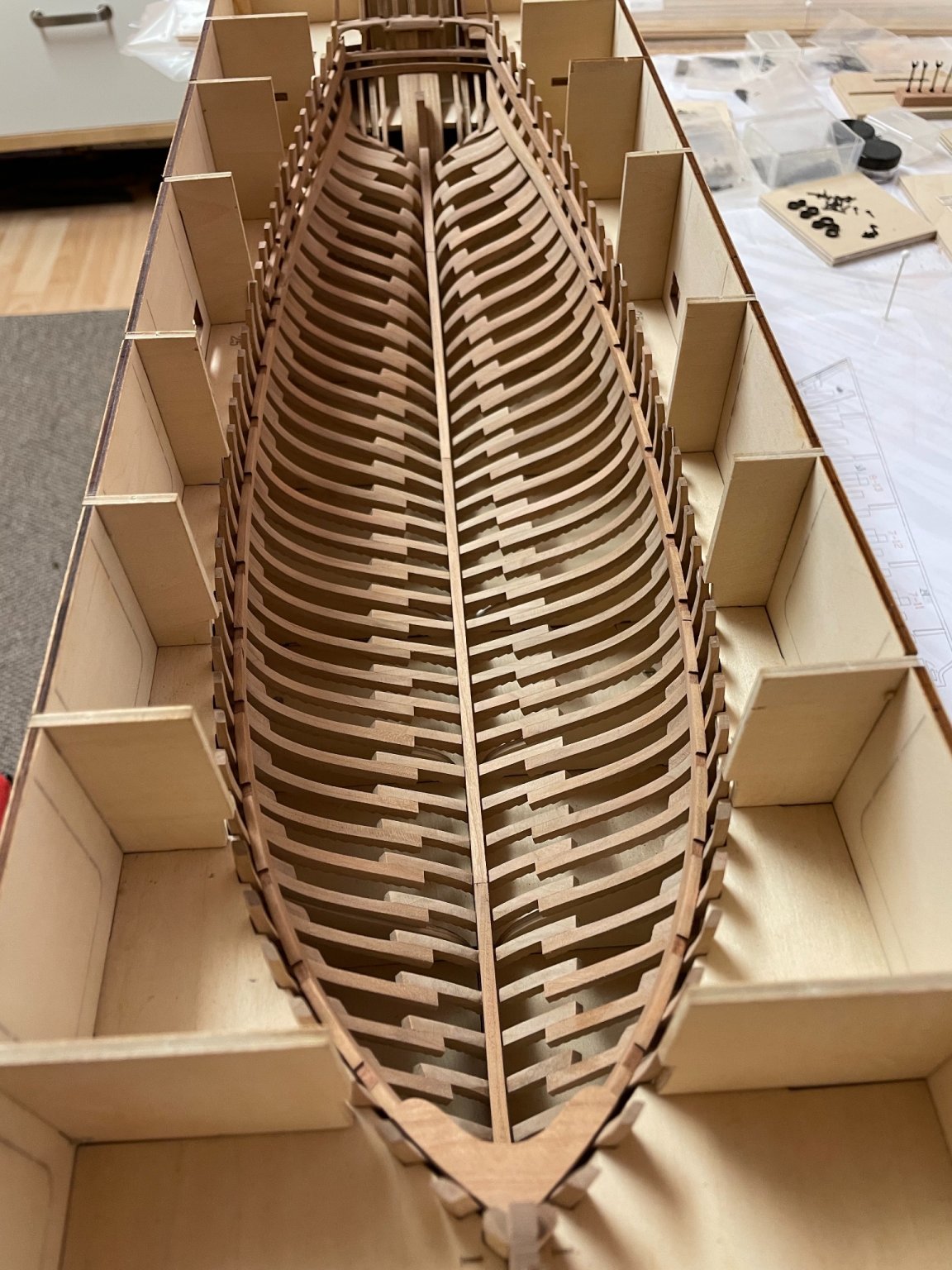
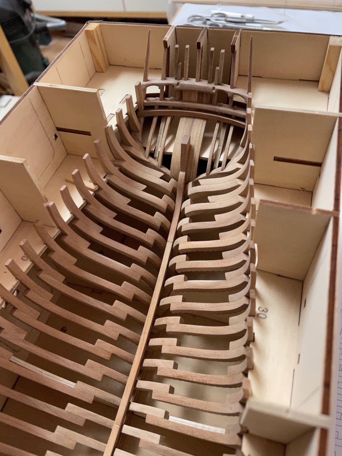
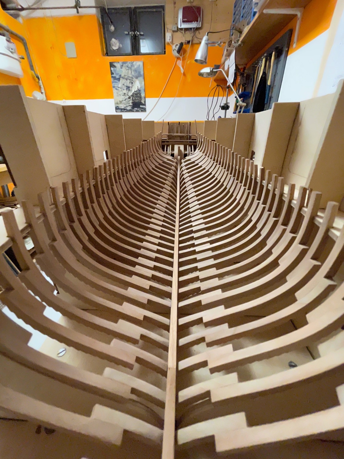
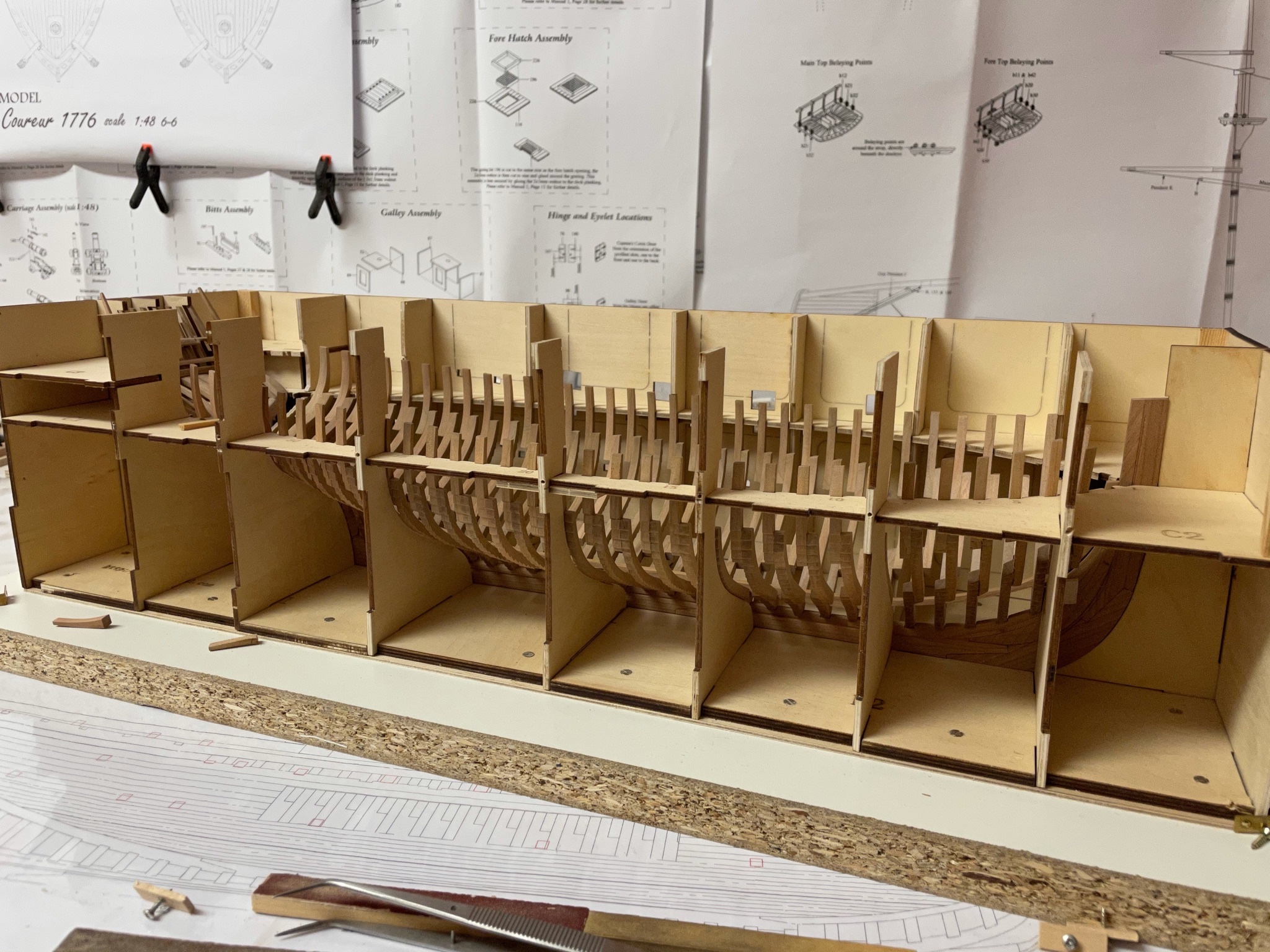
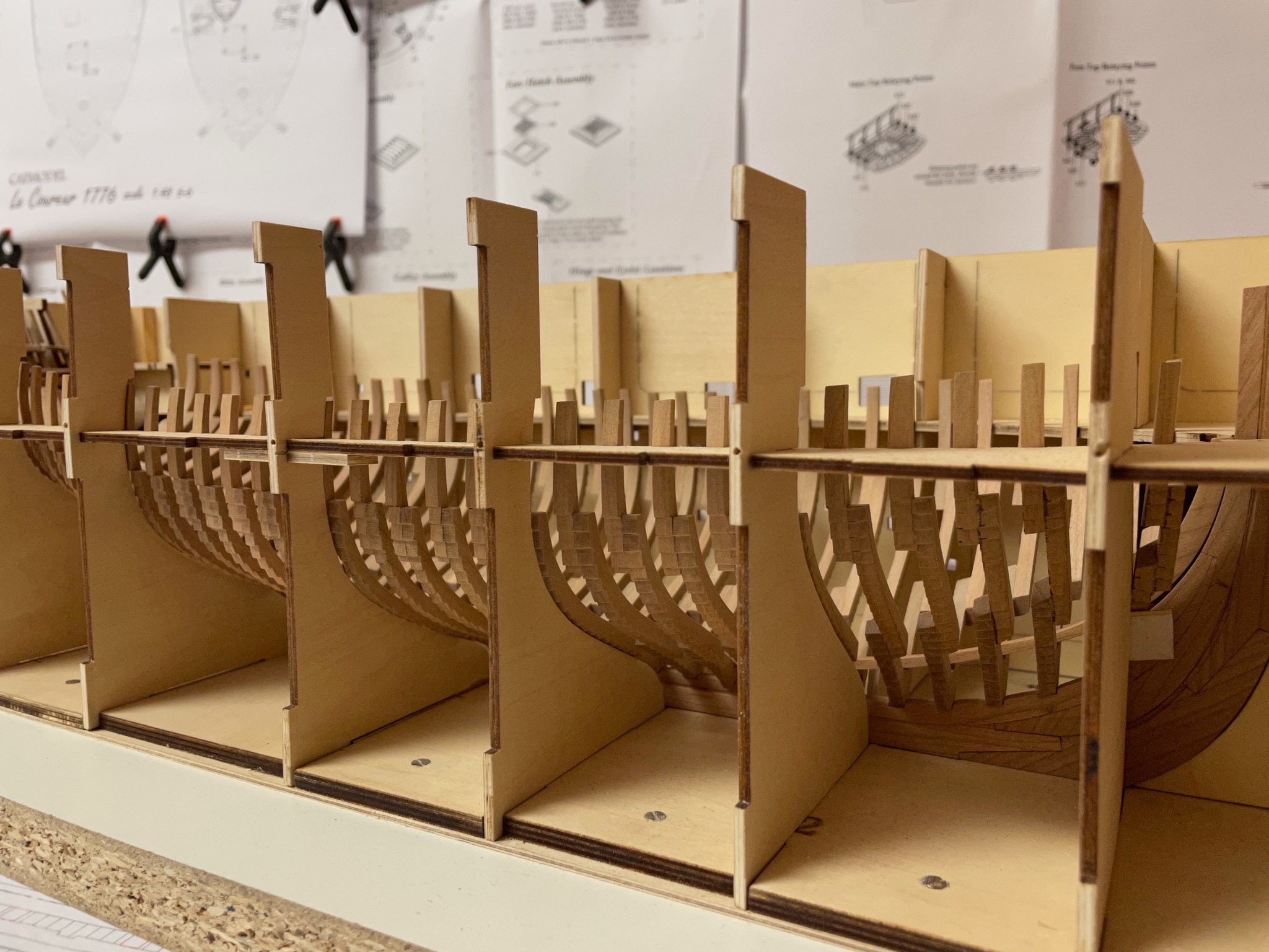
Thank you Brian. Today I finally glued all frames in place. Bad luck - it has been raining all the time with humidity growing every hour. The white glue took about an hour for every step to dry but at least that helped me correcting the frames until I was satisfied with the result. I started midships and then worked my way up to stern. I disassembled the left-side panels of the jig to have a better view and left all frames in place so I was able to align the one to be glued onto the keel with the other ones. Approaching the stern ... There are several curves created by the lower, middle and upper futtocks to check the correct alignment. After installing the rear ones I continued my way from midship to bow .. So all frames except the cant ones are now glued onto the keel. I will add the keelson and cant frames next weekend. Stay tuned and save.. Andreas
-
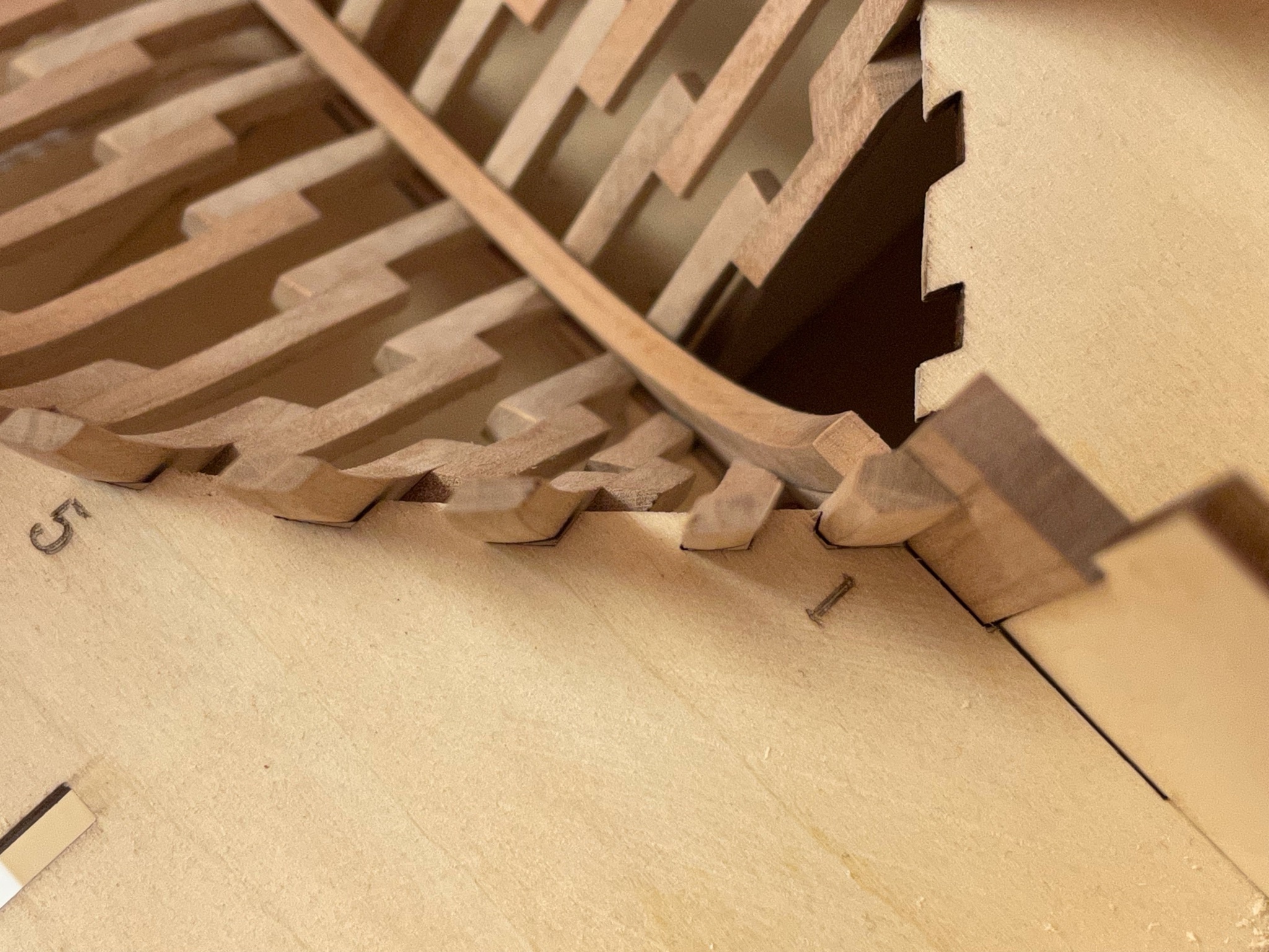
Today I finished all the counter-frames and glued them in place. The jig had to be modified for the frames to match the plan, Now all frames are separated by equal space (about 8 mm) like shown on the plan. Just some final sanding before the inner planking will be started. Next weekend I will start to glue all frames onto the keel starting with the stern frames .. Stay tuned and save. Andreas

-
As the jig was temporarily deconstructed I was able to take a sneak peek on the side ...


-
Thank you for all the likes. Frame no. 40 required a little surgery. The plan shows the frame on top of the lower transom .. but the middle transom has no cutouts for the frame. So I again had to deconstruct the jig and sanded just a little off the middle transom. At last the frame needed some tapering. Test-fit passed 🤗. Now I have to repeat that on the port side. 😰


-
Frame 38 and 39 proved to be more time-consuming than expected. Frame 38 is made of two segments and then has to be tapered to fit the counter. Still dry-fitted I have to squeeze some scrapwood into the jig to make it stay in place. Frame 39 is just a single peace that has to be tapered. Frame 40 is still missing. Stay tuned and save.. Andreas
-
Thank you very much Yves, this took most of the building time so far. The wood is rather soft and removing the laser char with electric tools is difficult because too much substance can easily be taken off. But I take my time. Only the last frames 38 - 40 and 1 - 2 have to be done, these are just single pieces added to the keel and counter. And then everything can be glued in place. I am heavily occupied by my self employment these days and this is slowing me down a bit.
-
The keelson is build up from 4 segments. The slots have to be cleaned and checked first before installation, so that the frames will fit into them later. Test-fit on the plan.. ... and on the frames. Still nothing is glued yet. I will make some final adjustments next weekend. Stay tuned and save. Andreas