HOLIDAY DONATION DRIVE - SUPPORT MSW - DO YOUR PART TO KEEP THIS GREAT FORUM GOING! (Only 51 donations so far out of 49,000 members - C'mon guys!)
×

captain_hook
-
Posts
685 -
Joined
-
Last visited
Content Type
Profiles
Forums
Gallery
Events
Everything posted by captain_hook
-
 You‘re doing a very nice job. I‘m a little afraid about sanding the char off the frames. They look very fragile and might easily break along the direction of the grain.
 -
I like the idea of using CNC-milling instead of laser-cutting very much. Snug joints without the need of sanding char away.
- 67 replies
-
- 4
-

-
- granado
- cross-section
- (and 1 more)
-
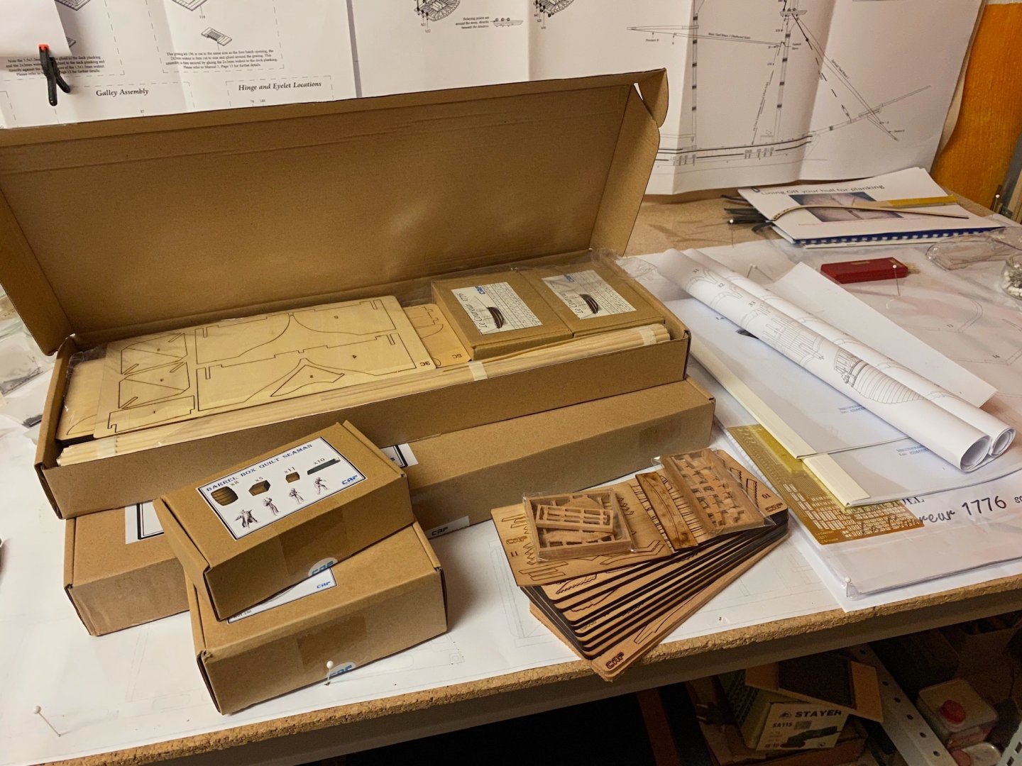
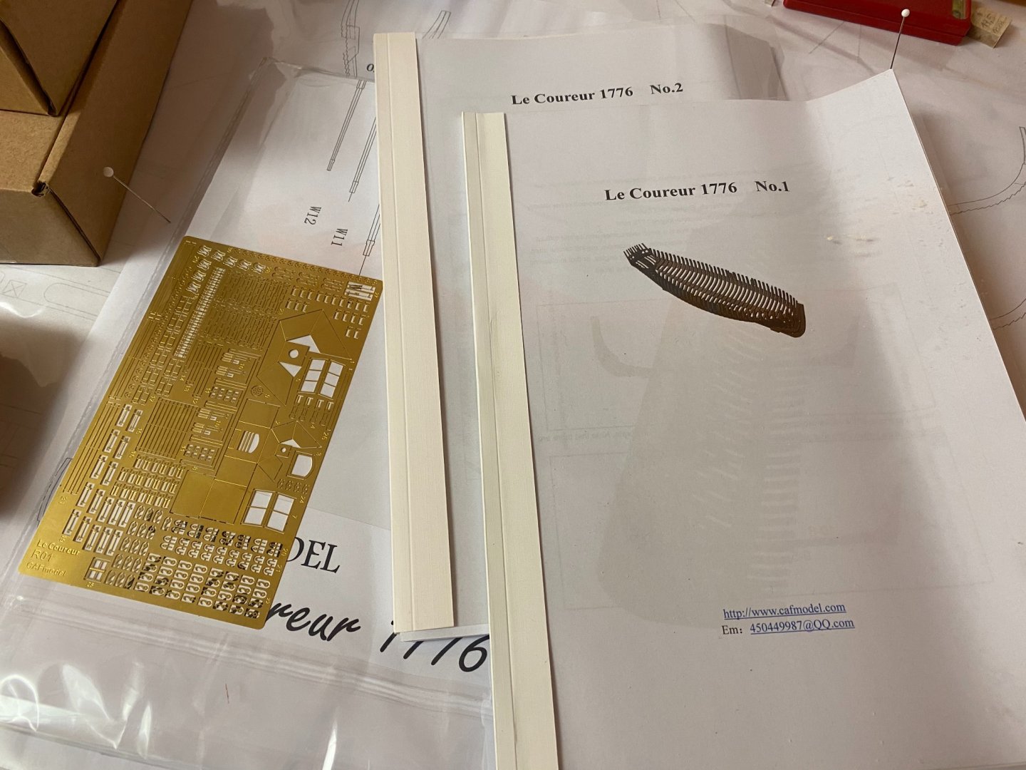
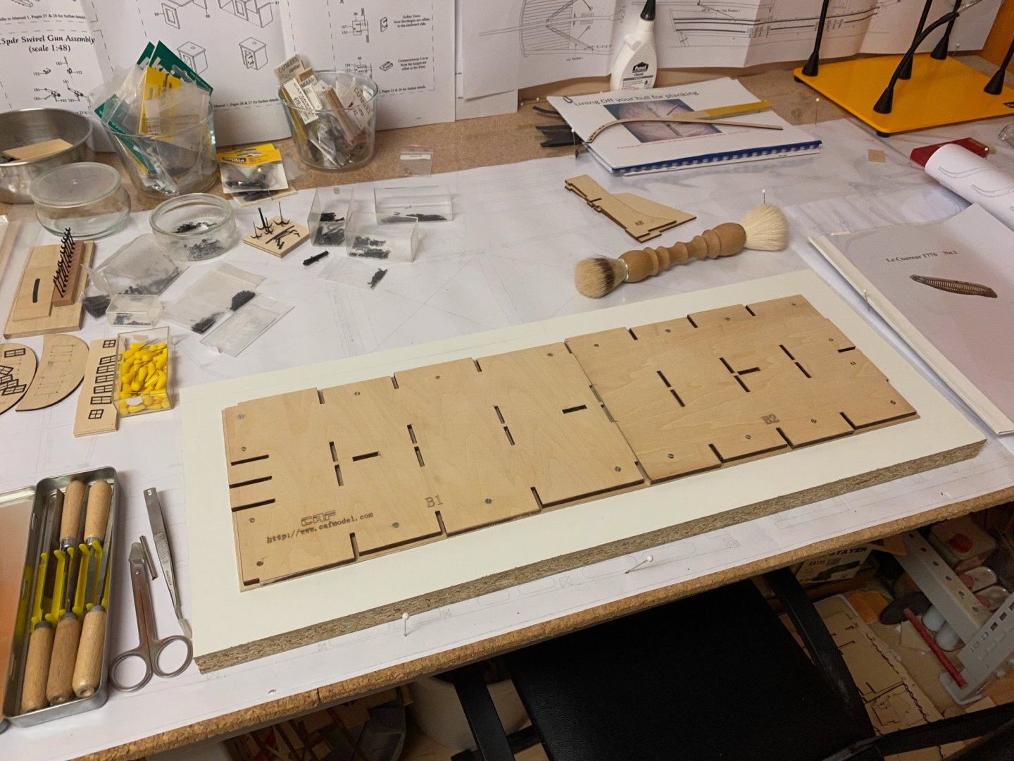
Hello everyone, this is my fourth kit-build and my first POF build. I couldn‘t resist to buy this one because of its beauty and grace. Some months ago I finished my last build and I thought some time about what to build next. There are a lot of beginner kits but I found it difficult to choose the right „intermediate“ kit. I started the Caldercraft 1:64 Granado kit I had in storage for a long time soon to find out that CAF is designing a 1:48 POF kit of the Granado. So I have put that build on hold until CAF has finished the developement. If it will turn out well, I will eventually start that one. But meanwhile? The Badger is more like an experiment, which will take a lot of time researching and I have to think about every step. How about a nice little side-project, that is challenging enough to keep me busy until CAF‘s Granado will be finished? Having followed the banned kits threat for a while I was afraid about buying a Chinese manufacturer‘s kit because I expected less experience with kits than established European and American companies already have. But CAF is something like a startup and I decided if I won‘t give a talented designer like Tom of CAF a try, other Chinese companies that still sell pirated kits in the first will never get encouraged to chance their attitude. So I ordered the kit, a barrel box and a cutter and got all items three days ago. My first impression was - wow! I have also ordered the Le Coureur book from Ancre and will use it as another source for reference, but it will take some more days to arrive here. James H. already did a nice and substantial kit review, so there is little left to say about the kit. It comes in two medium boxes, but both stuffed with lasercut wooden parts, stripe wood, accessoires and plans. As far as I can see, the quality of all parts is excellent, although cherry is not my favorite wood this might be my first kit it won‘t be necessary to substitute any wood. The keel is to be assembled first and then the cradle has to be done next. I made a small step first to assemble the bottom of the cradle and fixed that to a plain MDF-board with some screws. Will begin assembling the keel within the next days. Stay tuned...
-
Very nice. You did a wonderful job so far. I like the colour of the wood and the paintscheme as well.
- 238 replies
-
- 2
-
-
- sloop
- providence
- (and 1 more)
-
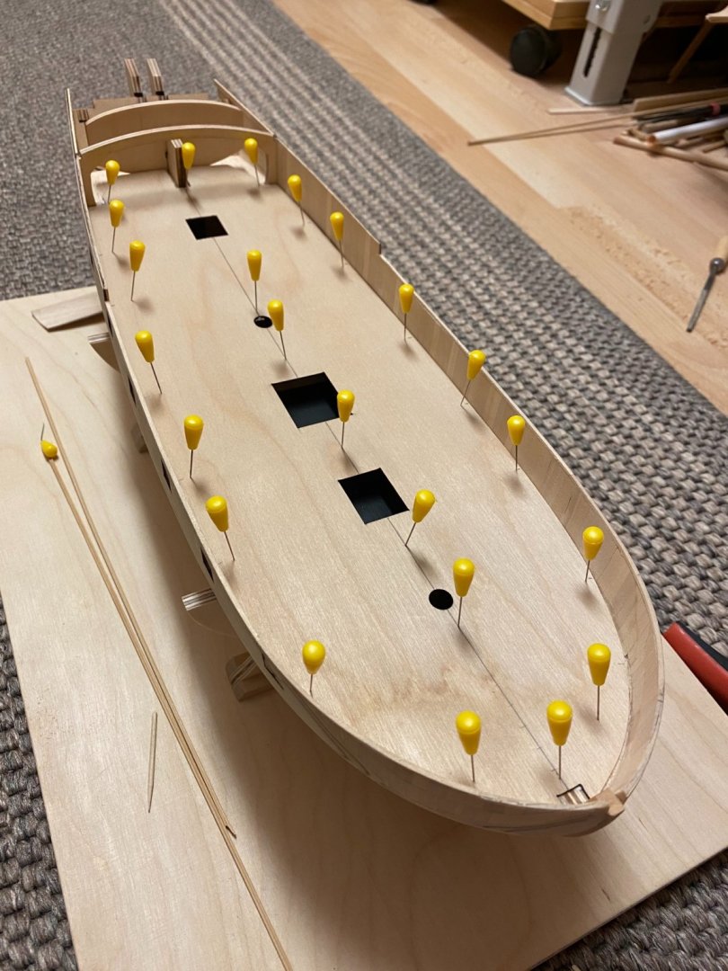
Thank you Mark. I sanded the bulwarks to equal height, following the deck and used a template as reference. Have to cut new gunports and then I‘m ready to add the keel.

- 64 replies
-
- 10
-
-
- badger
- caldercraft
- (and 1 more)
-
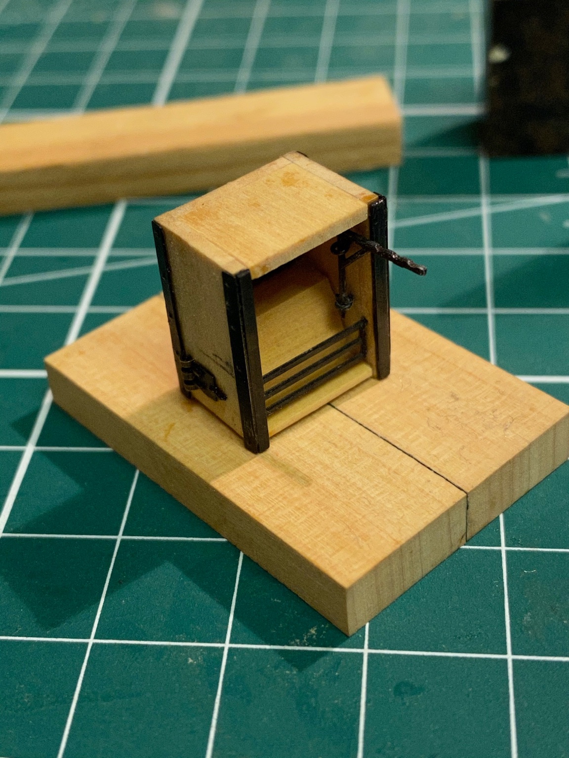
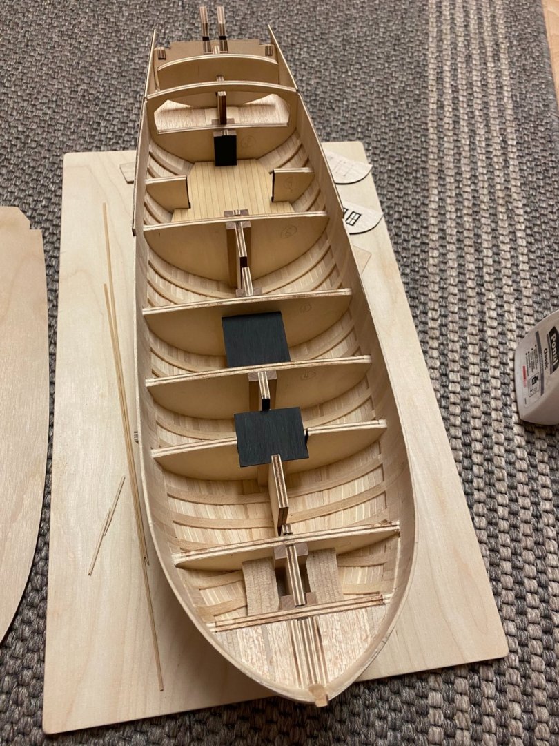
Thank you barkeater. Yes, I will leave it open. Have to redesign the galley to enlarge the opening a bit.
-
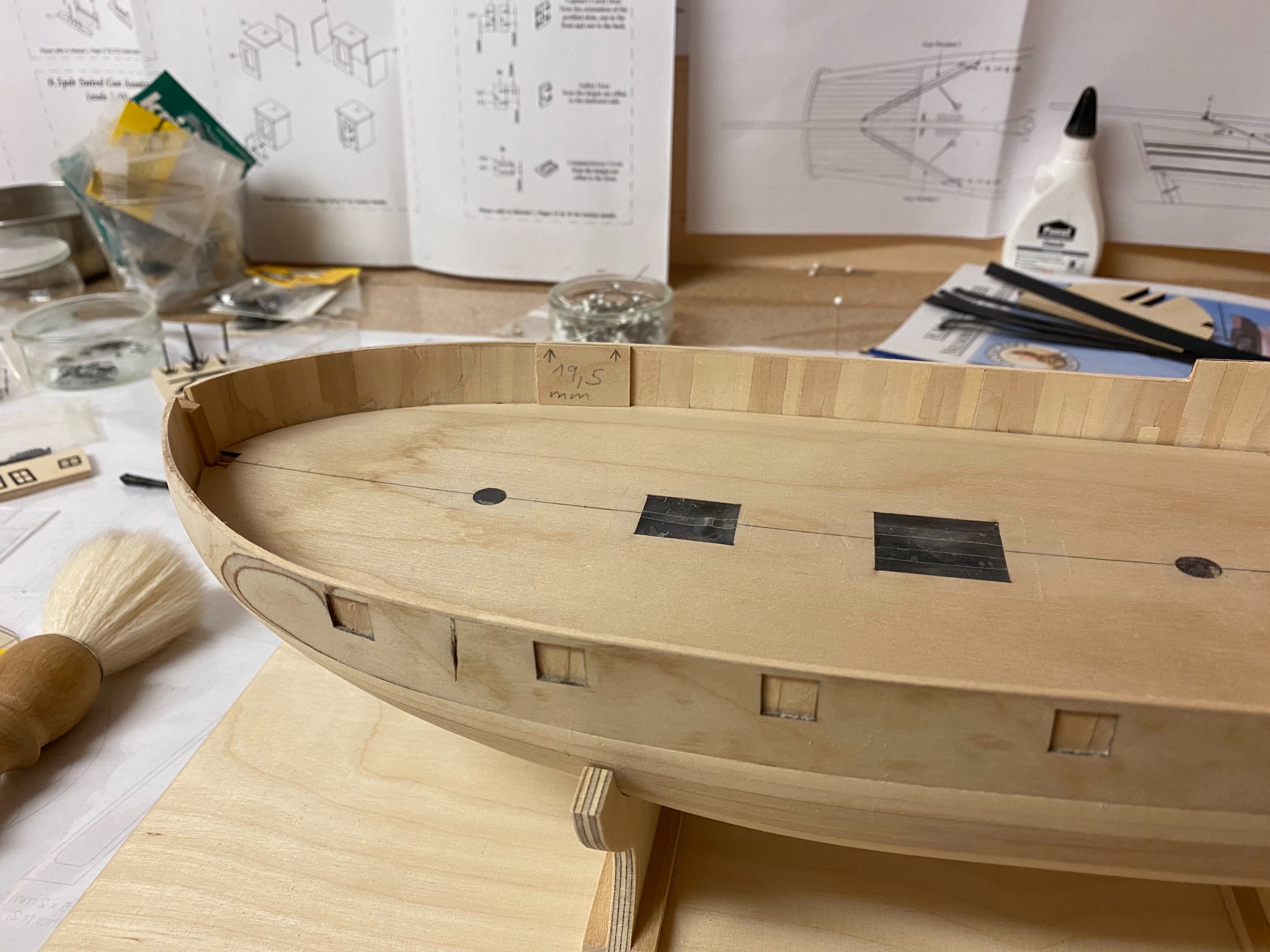
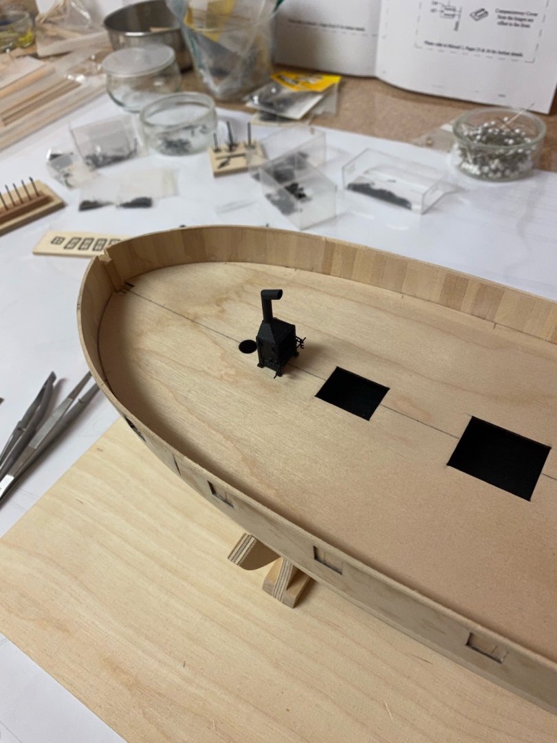
Thank you Jean-Paul. The supplied oven is nothing more than a box. But scratchbuilding a more scale one in 1/64 scale would have been tough... BTW this is the place where the oven will be placed later. It will be surrounded by a galley as well.
- 64 replies
-
- 7
-
-
- badger
- caldercraft
- (and 1 more)
-
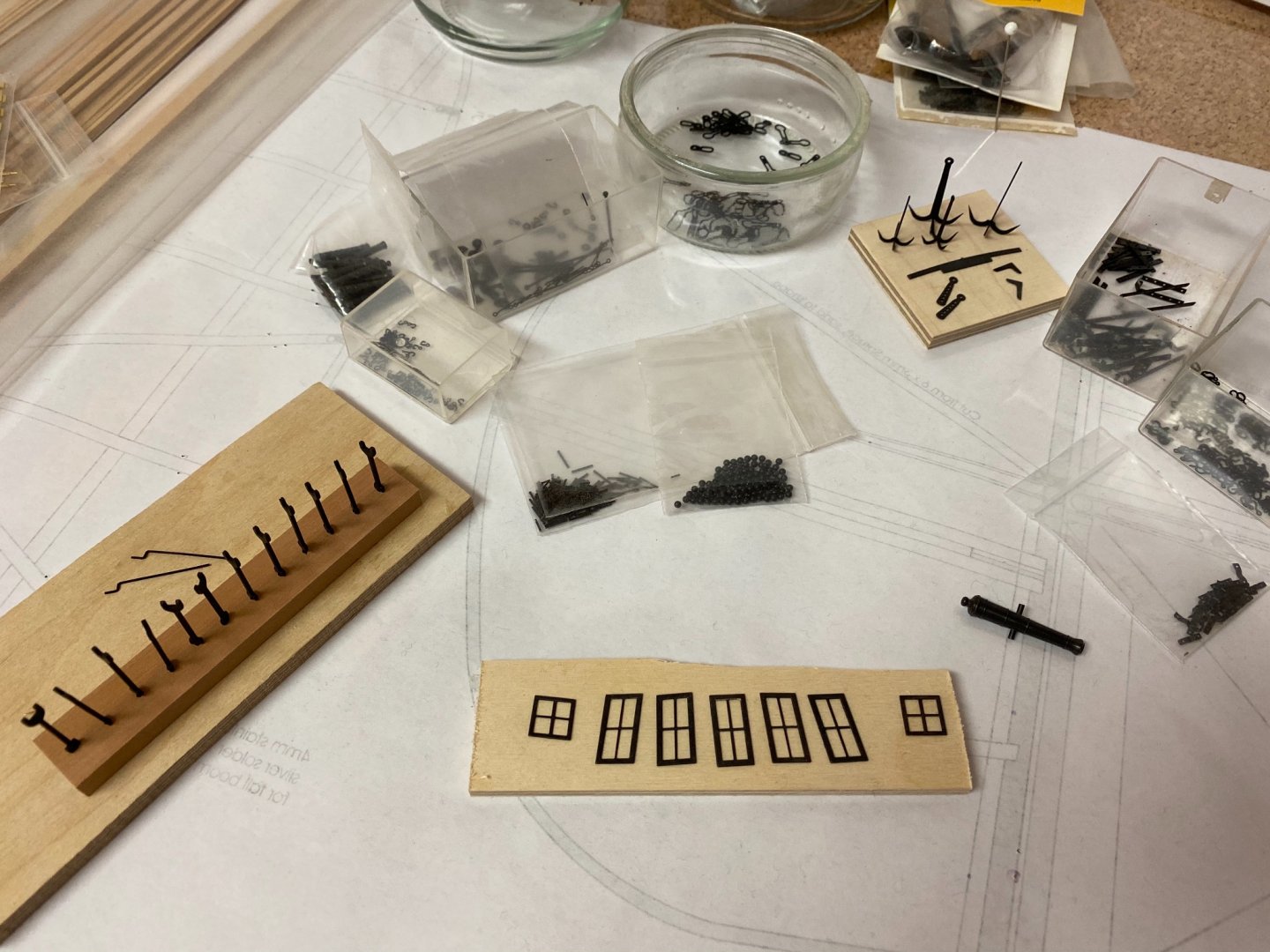
Prepairing all fittings slowed me down during my last build but this time I have already prepaired them all. Now back to the hull. I glued all subdecks in place and then the false deck.
- 64 replies
-
- 9
-
-
- badger
- caldercraft
- (and 1 more)
-
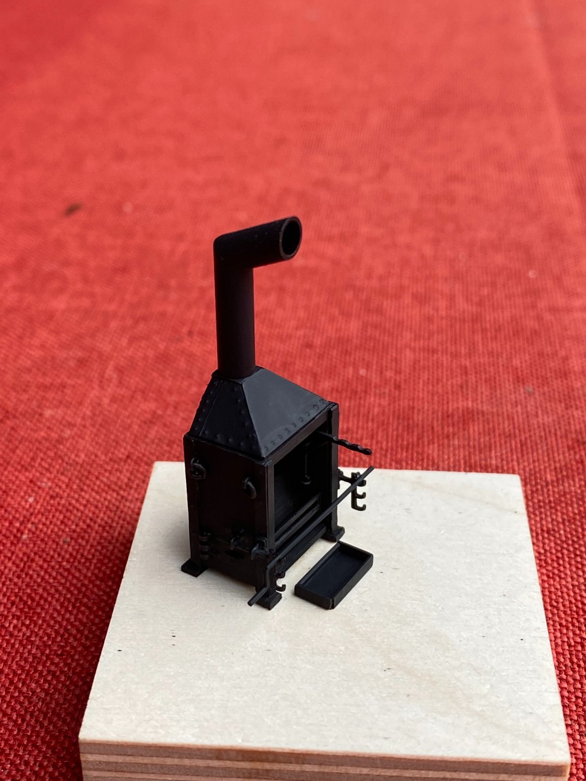
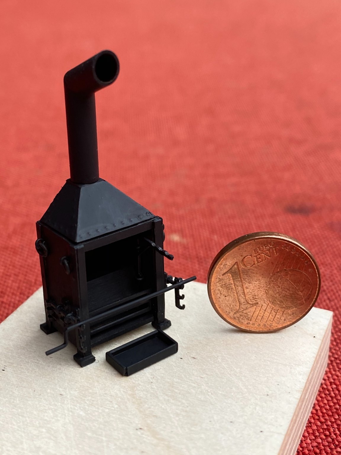
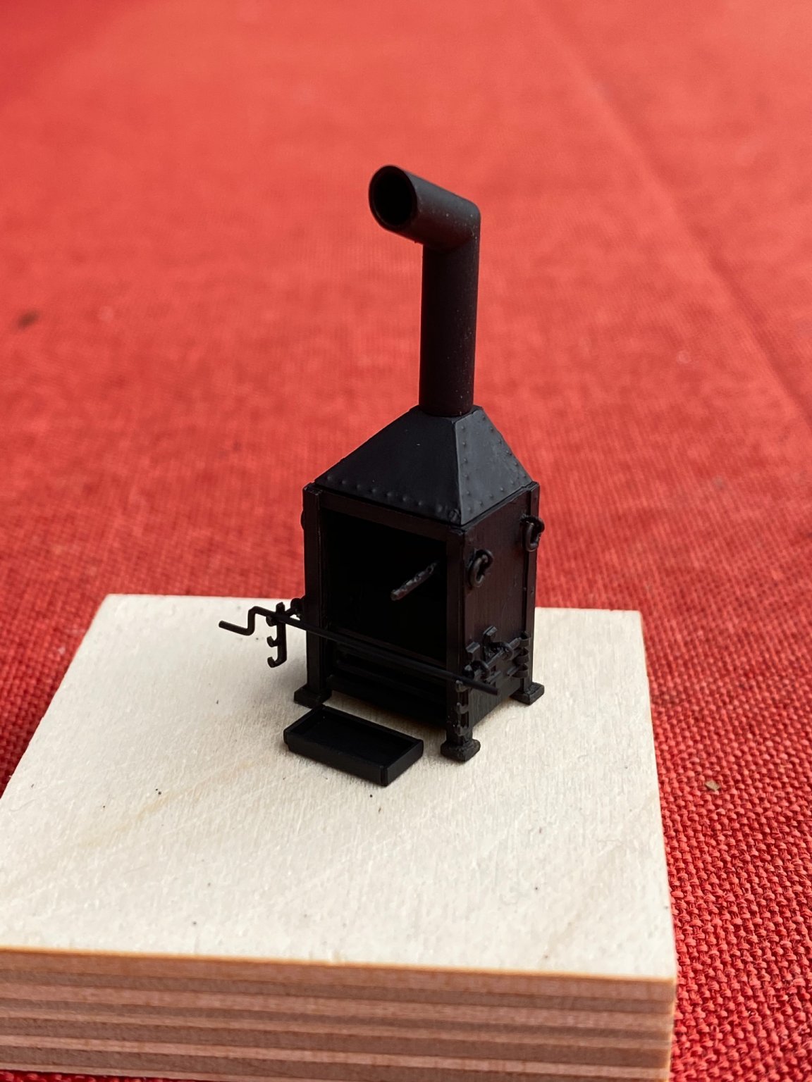
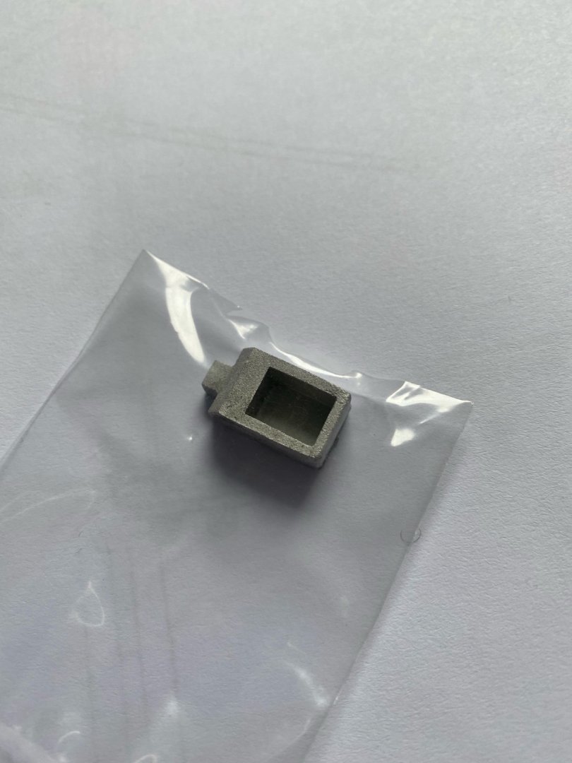
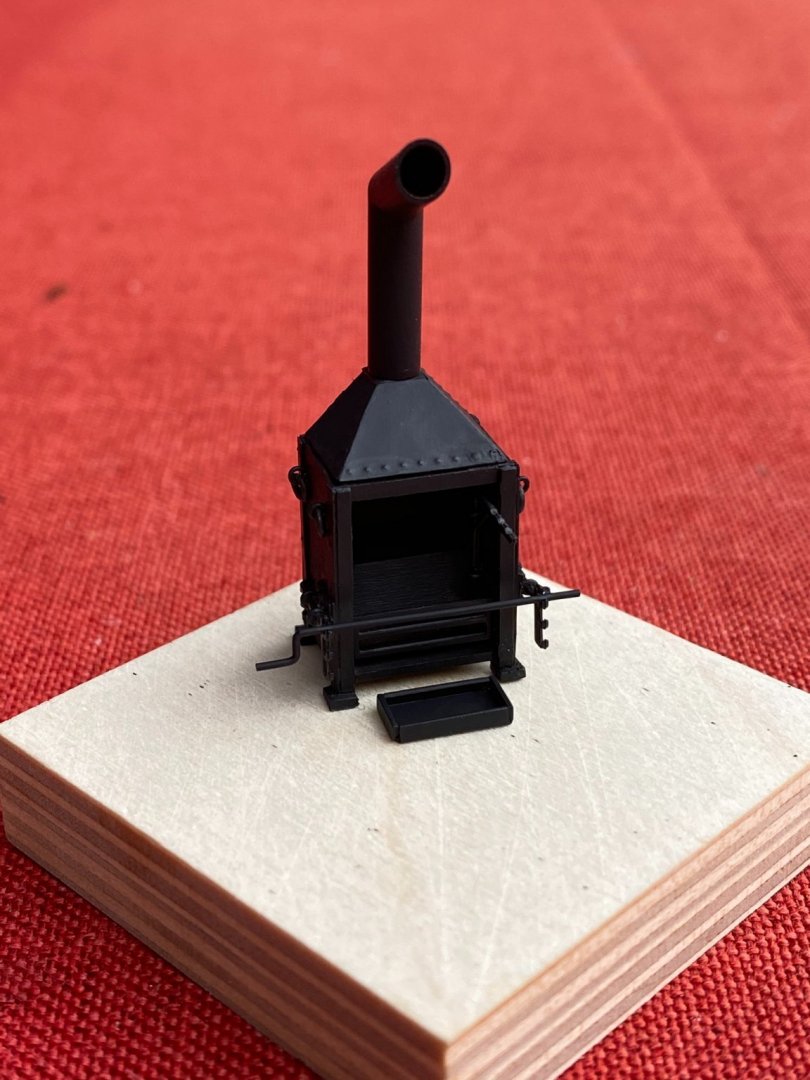
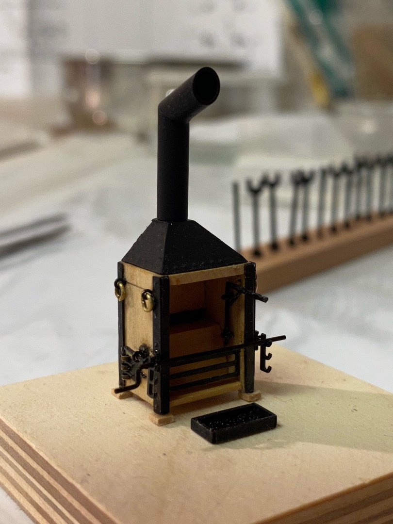
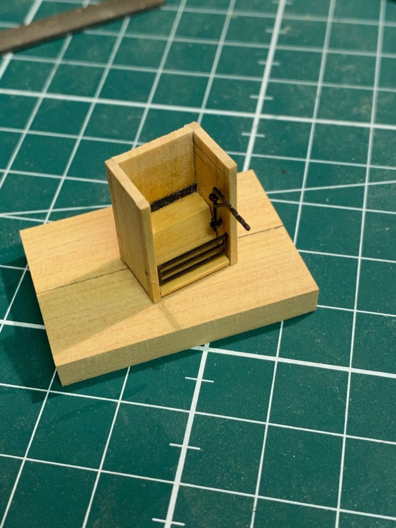
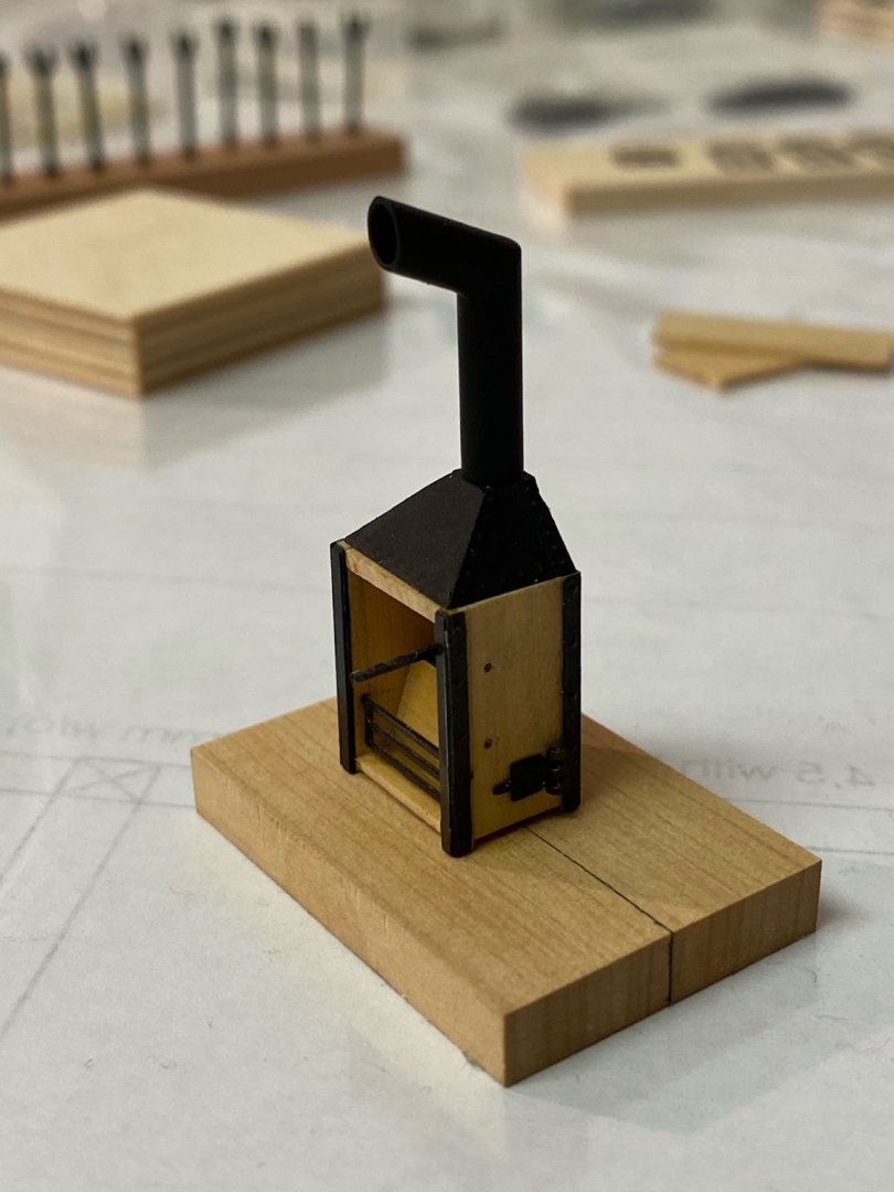
Building time is limited these days so before I start more work on the hull I wanted to do a little side project, the ship‘s oven. As a reference I used a picture I found on MSW in another thread. It was rescaled to match the scale of the build. The original kit supplied one is just a box made of britannia casting and the chimney is attached to it. I started with building the basic structure made of wood. The assembly is basically made of boxwood sheets with some brass parts attached to it with epoxy. Then the brass parts were attached. Put the whole assembly in my electrical stove after attaching the parts to each side and heated it for 10 min. (100 C Celsius) to reduce the cure time of epoxy. Instead of an angular chimney I decided to use a rounded one to match the one in my plans. The whole assembly with all parts attached to it but without paint. ... and after painting it with oxid black acrylic. Will add some clear vanish just before final installation.


- 64 replies
-
- 10
-
-
- badger
- caldercraft
- (and 1 more)
-
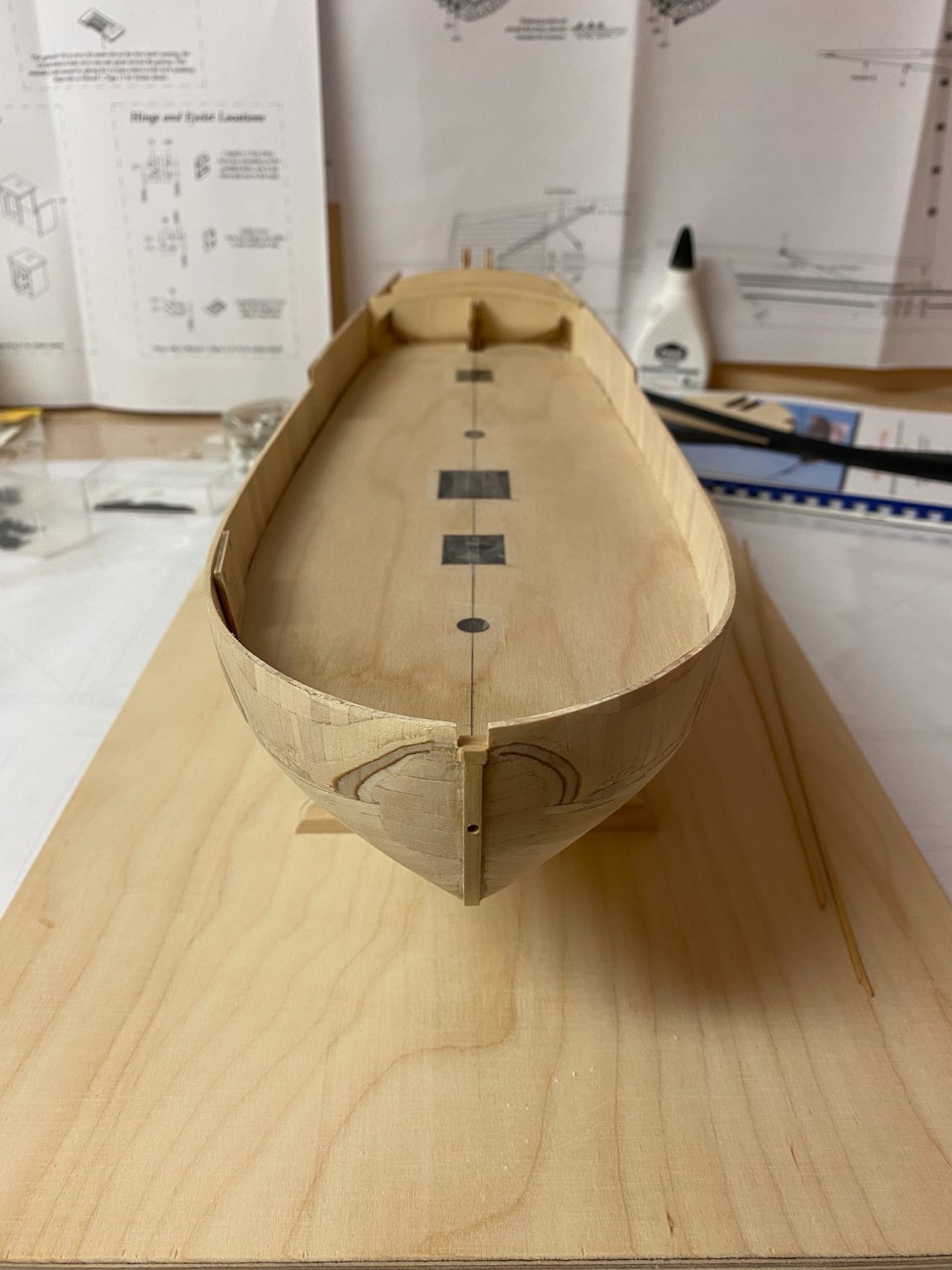
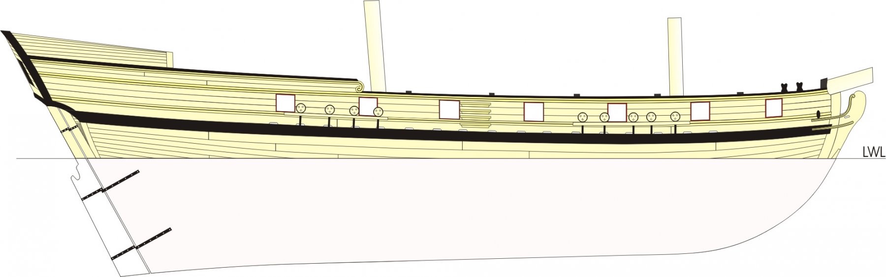
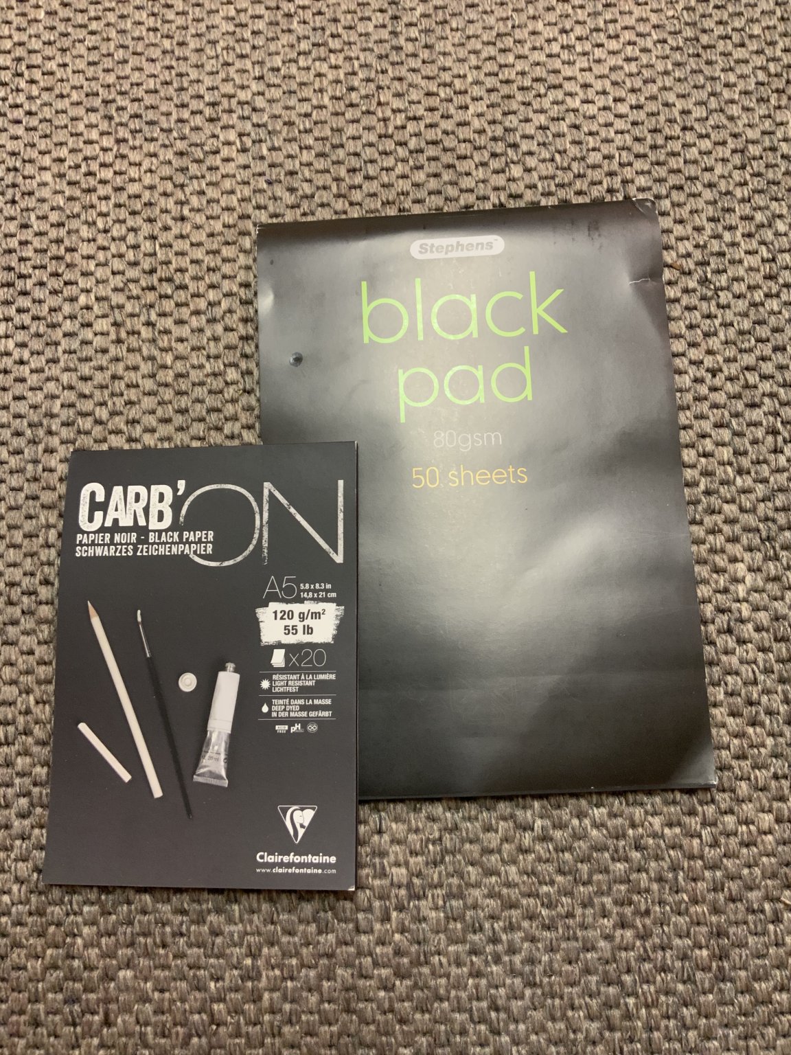
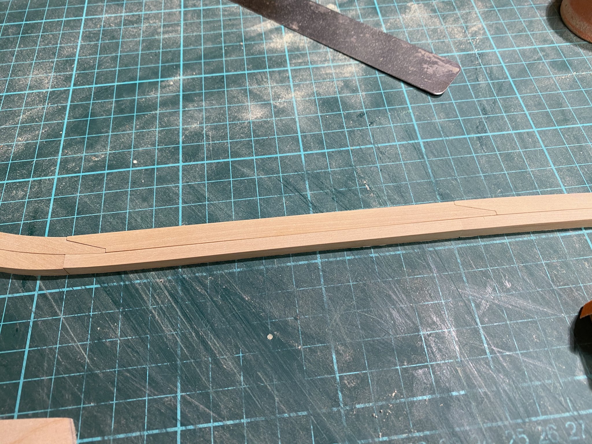
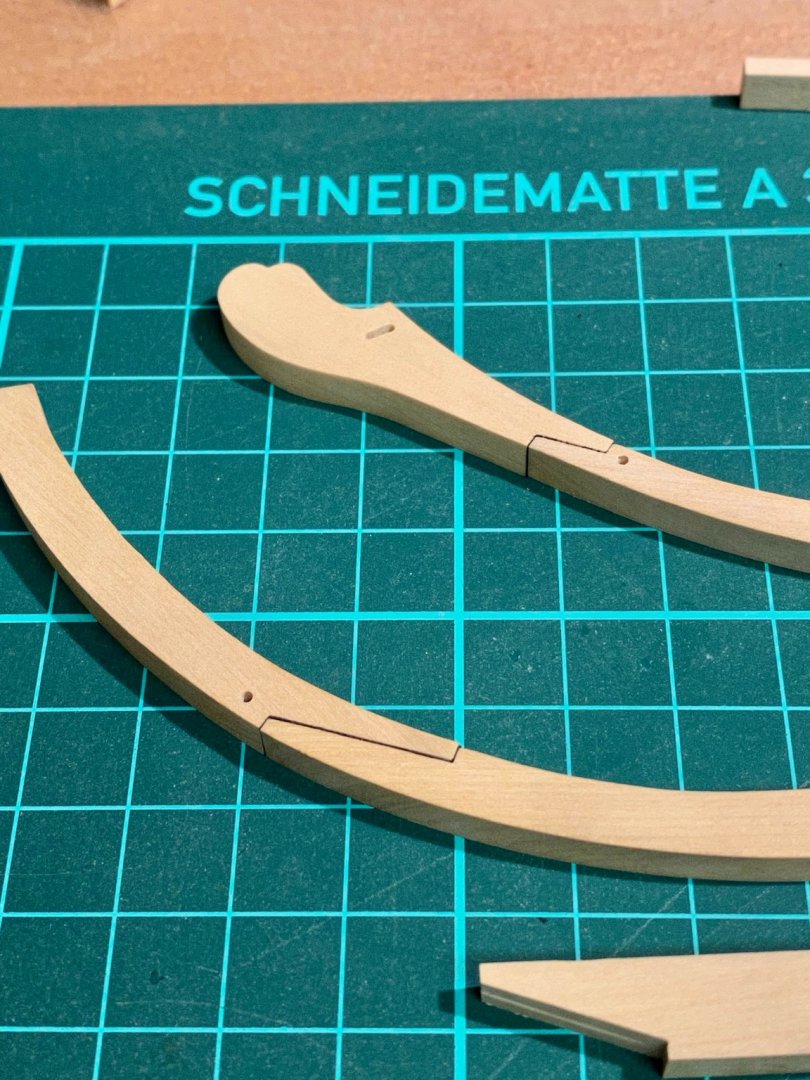
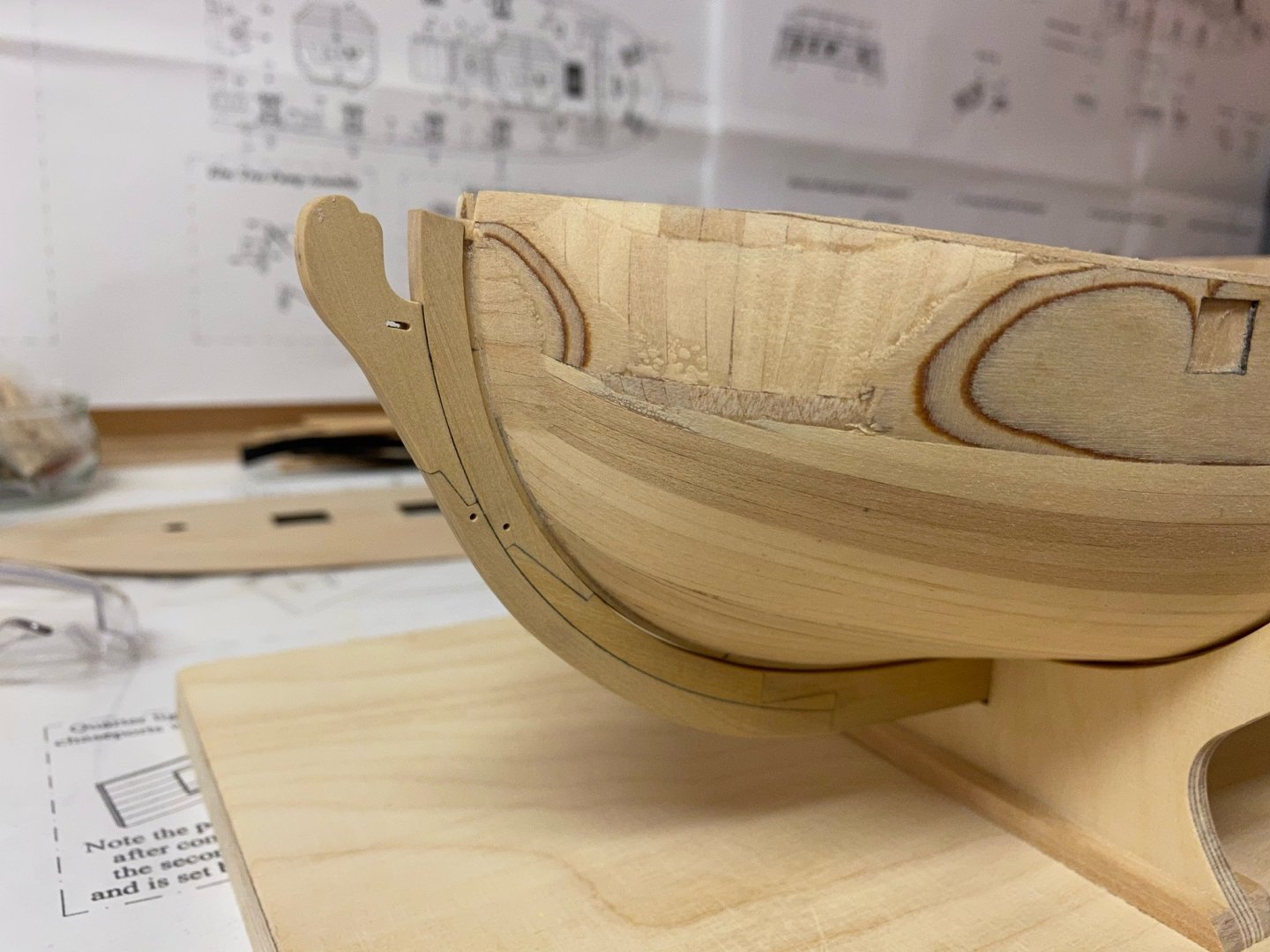
Some weeks have passed and I finally was able to spend more time in the workshop. For simulating tarred joints I first glued the paper on one of the two parts that are joined later. I use two different paper weights (80 gsm and 20 gsm) to simulate different strength of joints. As I haven’t found enough information about all keel parts and how it was build I finally decided to paint the hull white below the waterline so I only have to build the knee. It is exactly shown on the NMM plan. For the keel I will use a single part. Holes were drilled into the paper so the glue can penetrate the wood on the opposite parts. Both parts were then glued together to form a joint. Both sections were then glued together to form the knee. Another layer of paper was used to separate both sections. The keel was added at last. Dry-fit on the model. I still have to taper the knee and cut the gunports before the keel will be glued on.

- 64 replies
-
- 10
-
-
- badger
- caldercraft
- (and 1 more)
-
Very nice. This kit is on my list of possible future projects. I‘m curious how it will turn out..
-
Fantastic build and interesting subject!
-
Thank you Jim for the information., that is very helpful.
-
Hello everyone, now I have some wood in stock I think about expanding my tools-setup to cut sheets and strips myself. I have already decided to buy a Byrnes saw but I‘m not sure which accessoires are useful too. I will surely add a metric micrometer-stop and another 3‘‘ kerf. I understand that every accessoire has its own usefulness but maybe my english and my knowledge of tools is incomplete. Can anyone tell me please what a Rip Fence, a Rip Taper Gage and a Miter Bar are used for? Best regards, Andreas
-
Very nice, Jean-Paul. I also had to fix one swivel-gun stock, did all of them analog to the plan but unfortunately one interfered with a deadeye.
- 164 replies
-
- 1
-
-
- first build
- model shipways
- (and 2 more)
-
Nice build and rigging! The Cruizer-class brig is one of my favorites.
-
Very beautiful! I also vote for marple, but it may be another option to paint the support red to optically separate the boat from the simulated deck and add more warm colour, especially if you will use an acrylic case later.
-
Thank you Jean-Paul. A lot of preparation, so there is not much to see yet. I will use the cellulose as it looks more subtile. I have to sand a little more and then glue all parts together and taper the assembly.
- 64 replies
-
- 2
-
-
- badger
- caldercraft
- (and 1 more)
-
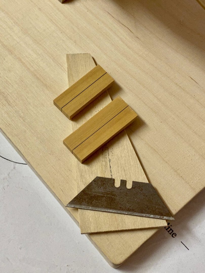
I made two test-joints with scrap. The one in the back is made with black paper (80 gsm), the one in the front is made with black single-sheet cellulose (maybe 30 gsm) I „borrought“ from my daughters desk. Both look very similar but the one in the front looks more discrete. Nitrocellulose-lacquer was used as varnish.
- 64 replies
-
- 7
-
-
- badger
- caldercraft
- (and 1 more)
-
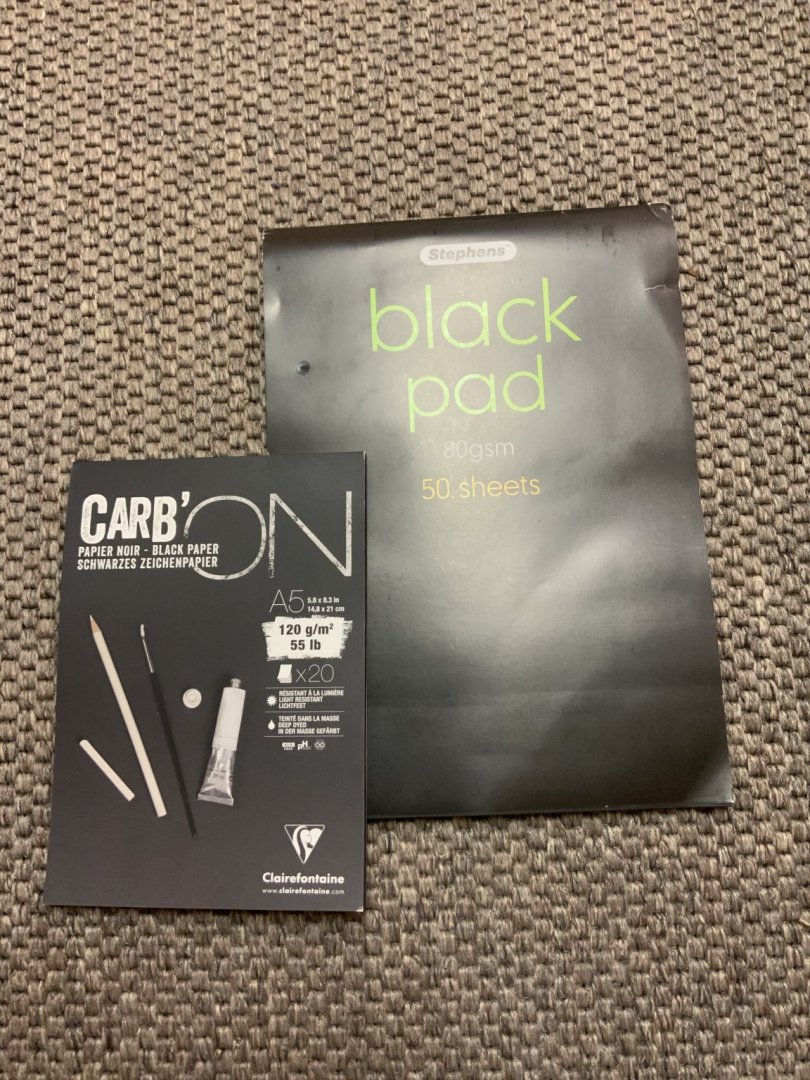
Thank you barkeater, I agree to that. I have finished all eight keel pieces and dry-fitted them. Got some 80 gsm and 120 gsm black acid free paper and I will try the simulated tarred joints on some scrap parts first. Anyone has a suggestion how to taper the „knee of the head“? I have only seen that on some bigger ships before but these ships’s had a different shape. The Speedwell and the Fair American seem to have a similar KOTH, maybe I should use them for reference.


- 64 replies
-
- 6
-
-
- badger
- caldercraft
- (and 1 more)
-
Nice work so far. Do you plan to add some decorations like sheer rails?
-
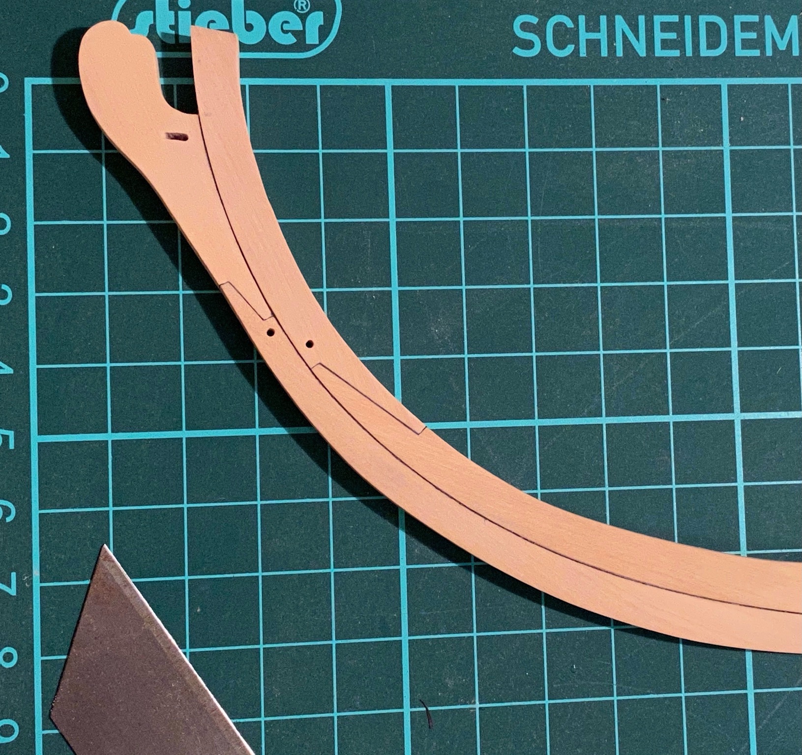
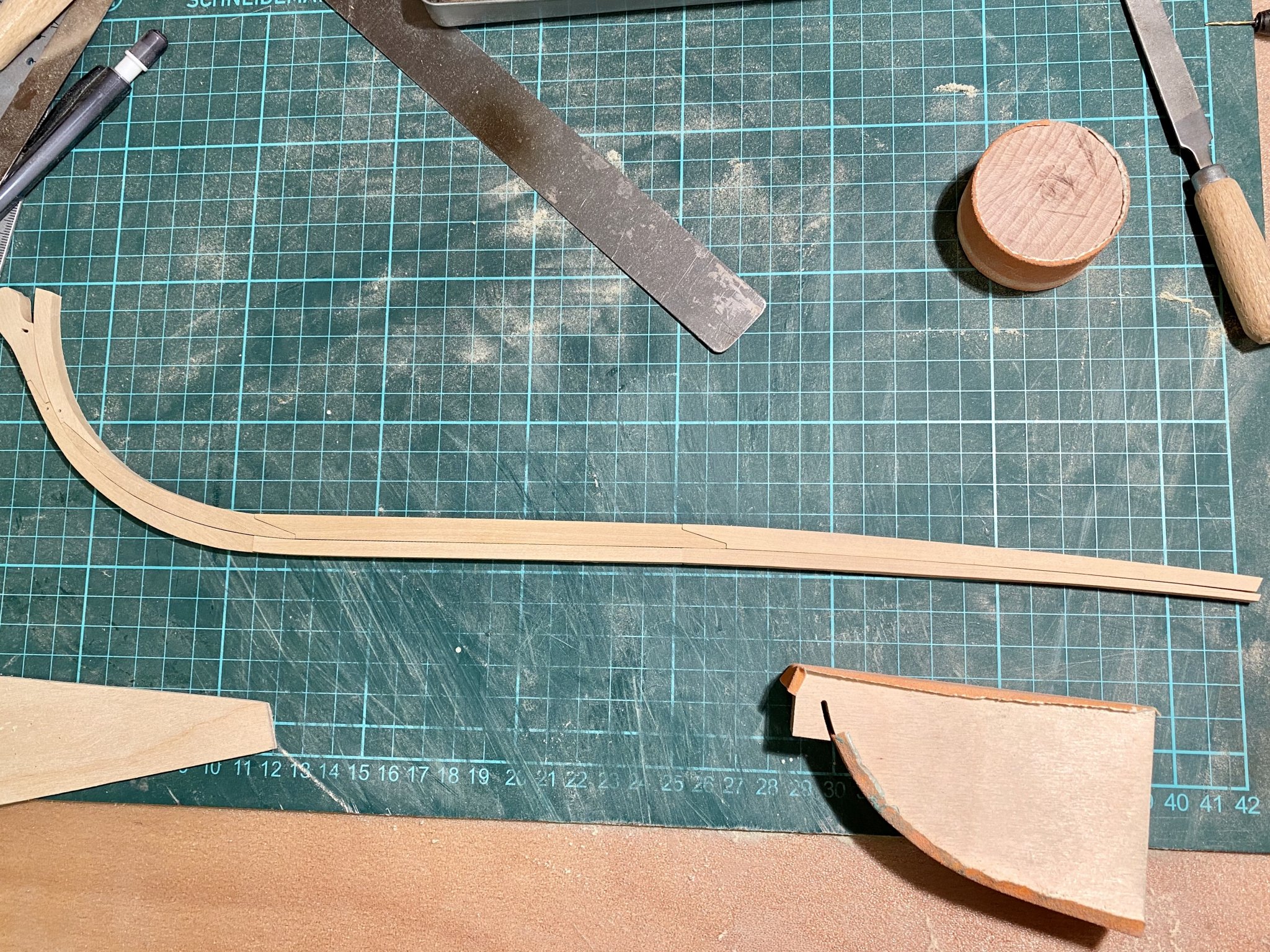
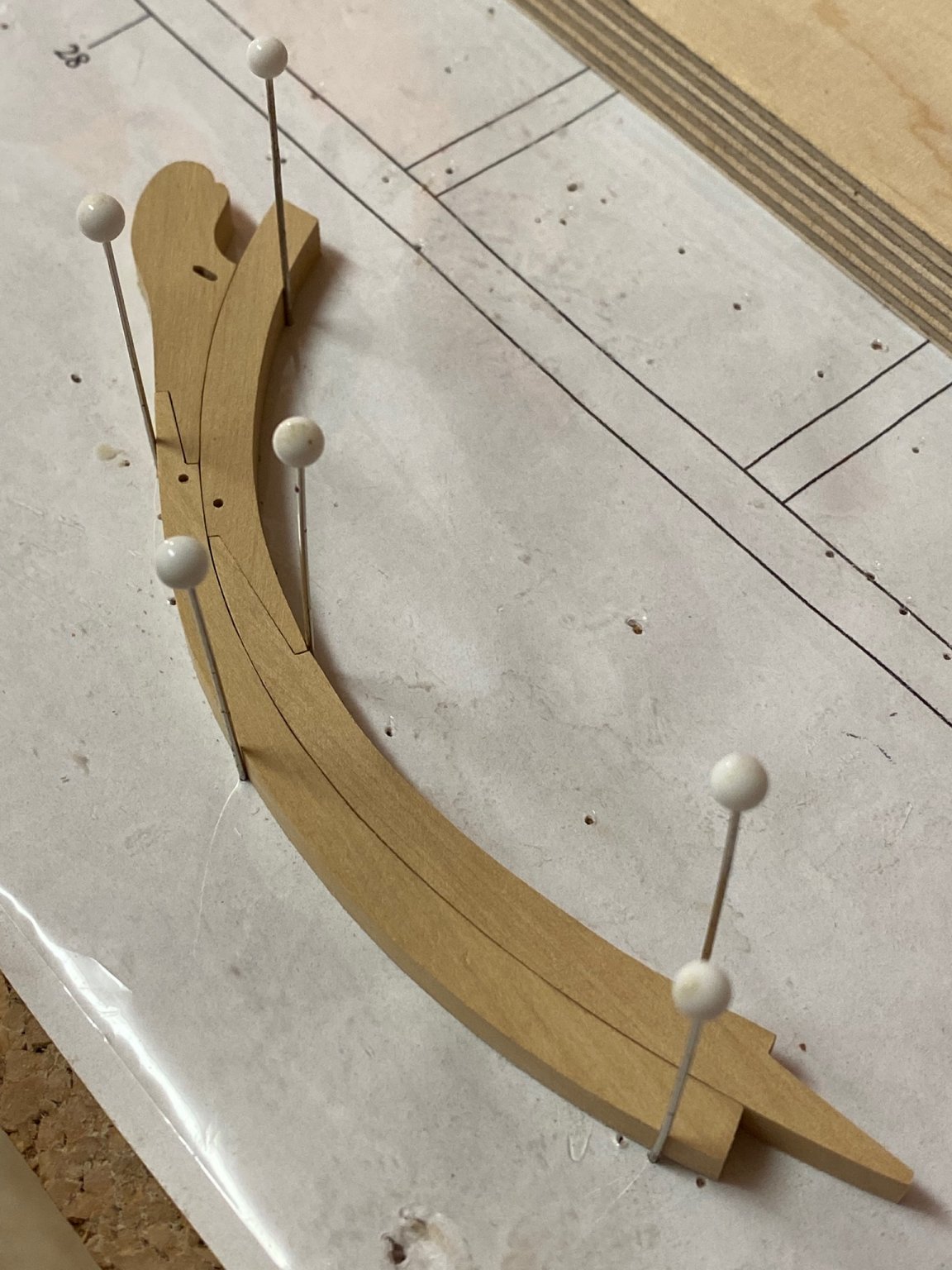
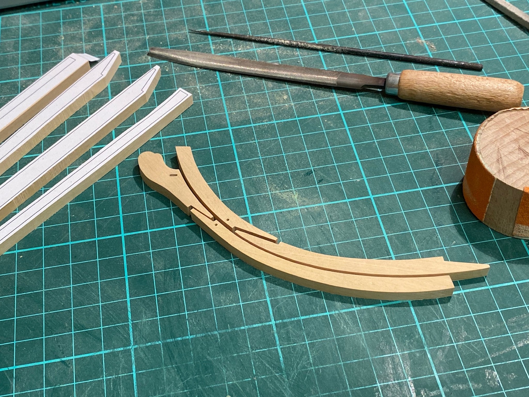
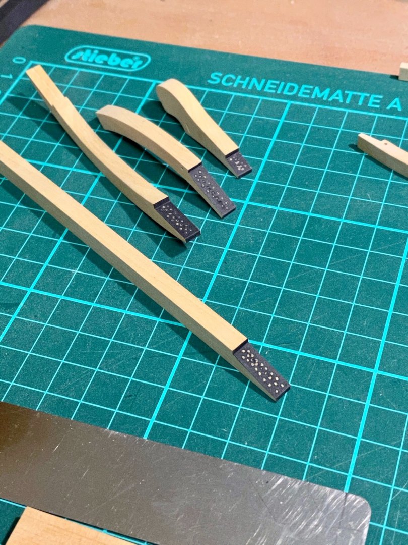
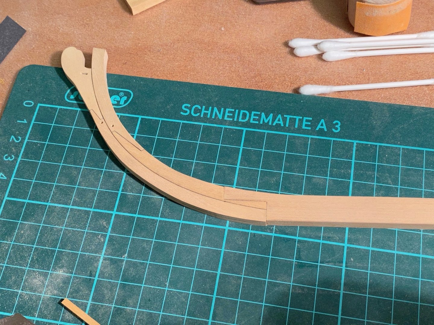
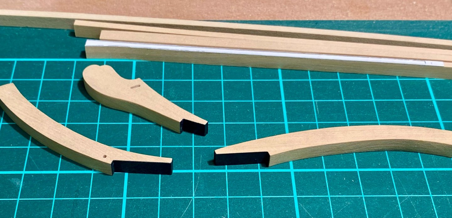
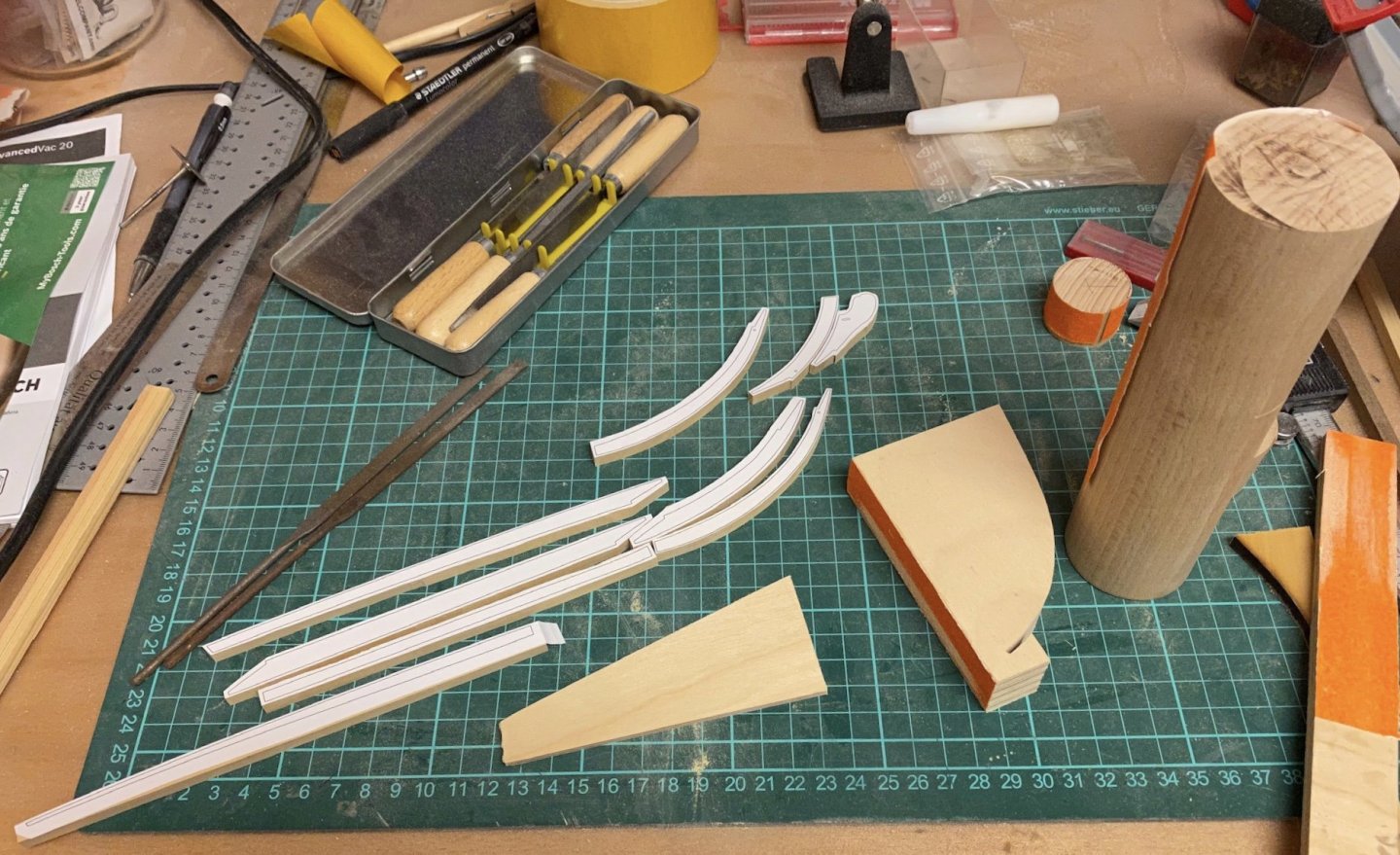
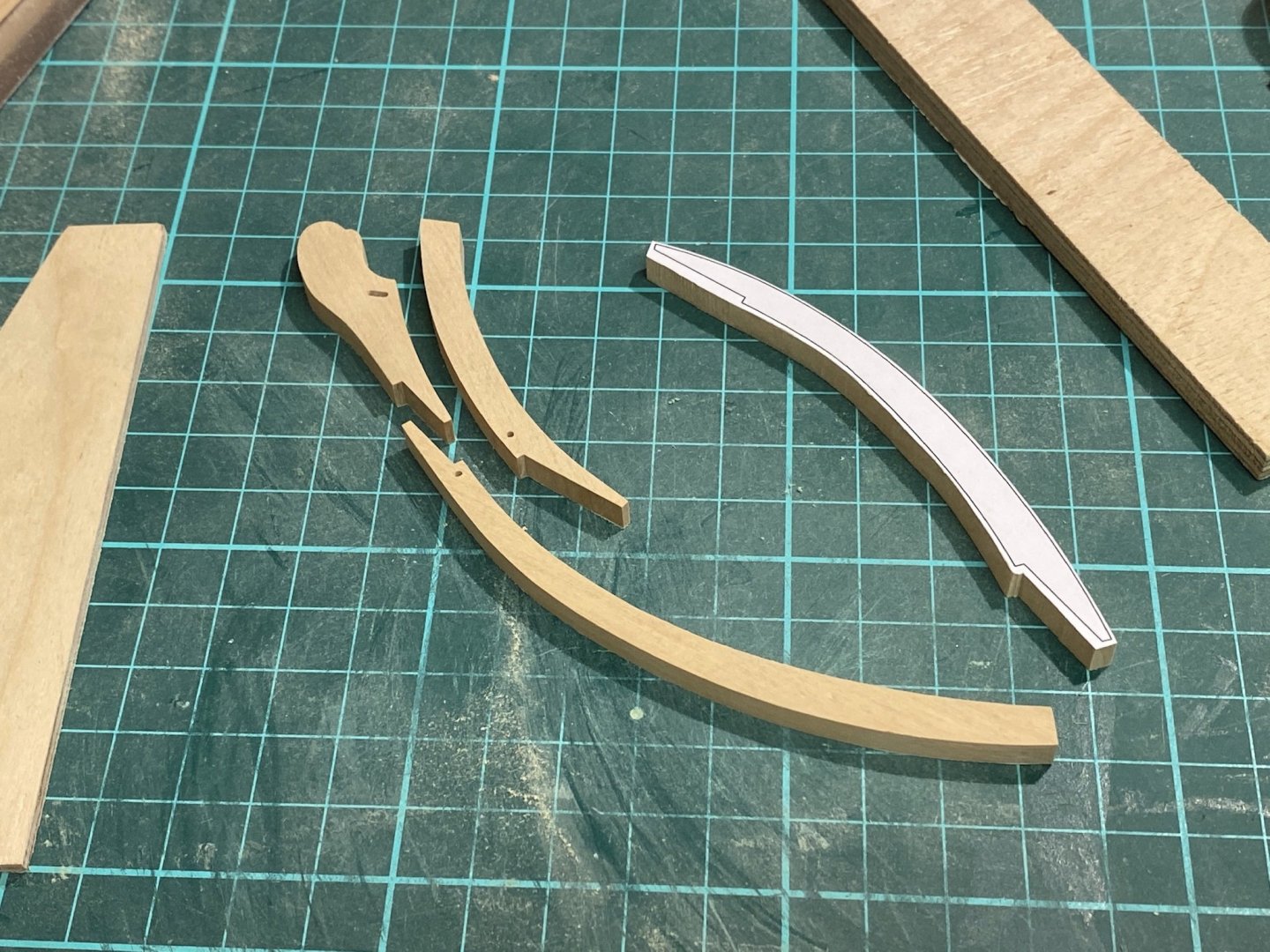
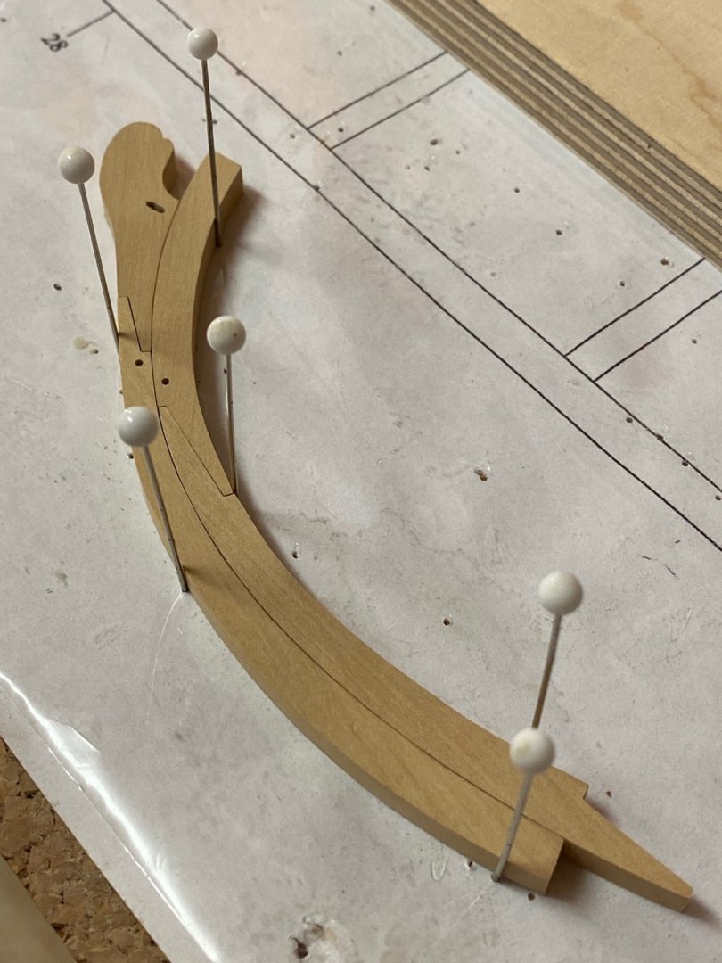
Thank you for the nice comments and the likes. The original kit supplied a simple 2-part keel for the Badger as it is supposed to be painted later. The NMM-plan shows a more complex multi-piece keel and I’m going to prepare both options to choose the final one later and gain more experience for future builds. For the multi-piece solution I first printed all parts on adhesive paper and glued them on 7/32“ boxwood sheets. Then roughly cut the parts with a scroll-saw and sanded them to shape with a Proxxon disc sander. The final sanding to snug fit was done with sanding blocks I made of different wooden blocks. The sanding paper is attached to the blocks with double-adhesive tape and the bottom of the blocks is sanded with the disc-sander so the attached sanding paper is orthogonal to the bottom of the blocks to secure no sloping will occur during sanding the keel parts. As the paper templates are still on I have to use some needles for a test fit. For the tarred joints I might try the paper method dvm27 explained pretty well in his Speedwell log. But before gluing all parts together I still have to find out how to taper the keel correctly. As this is my last day at home working in my workshop might slow down a bit during the next weeks.

- 64 replies
-
- 13
-
-
- badger
- caldercraft
- (and 1 more)