MORE HANDBOOKS ARE ON THEIR WAY! We will let you know when they get here.
×


Keith_W
-
Posts
1,145 -
Joined
-
Last visited
Content Type
Profiles
Forums
Gallery
Events
Everything posted by Keith_W
-
 Thank you Bindy, Bob, Michael, and Rich. The boat is FINISHED! I am waiting for my DSLR to return (I have loaned it to a good friend to take some honeymoon pics), then I will take some studio shots of this boat. I could have done more work on it as per the other build logs - e.g. make cutlasses, turn the barrels, etc. - but it would have made the finished result look too busy. Well that's my excuse anyway. Members in Melbourne will be able to see it tomorrow night when I bring it to the club meeting. The real reason was to clear space so that I can get started on my next project, HMS Royal William (see my signature).
- 78 replies
-
- 3
-

-
- model shipways
- bounty launch
- (and 1 more)
-
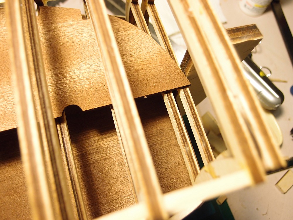
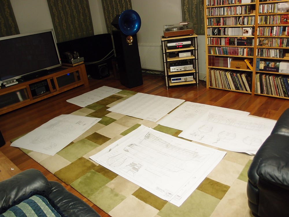
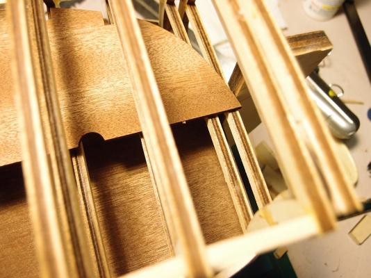
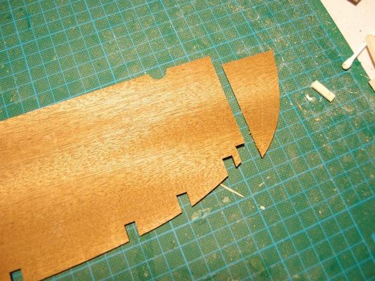
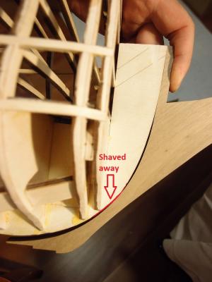
Here are a couple more minor kit issues. The middle gun deck is supplied pre-cut with a rounded bow section. However, as you can see, the rounded bow section will clash with the front bow filler block. The solution is to simply cut the deck and discard the piece. The keel describes a sloppy fit with the false keel. After checking with the plans, and confirming that the top of the keel is supposed to rise to the level of the main deck (if the bowsprit wasn't in the way), I shaved away the area painted in red. I now have a perfectly fitting keel. The kit doesn't include a mizzenmast support, so I fabricated one and installed it. My wife returned from a day of shopping to find that I had turned nearly every spare inch of floor space into reading space for Royal William plans! She was not very impressed, especially since I had not kept the modelling door closed and the dust was in the main living area. I had to put a stop to my modelling and vacuum the house.


-
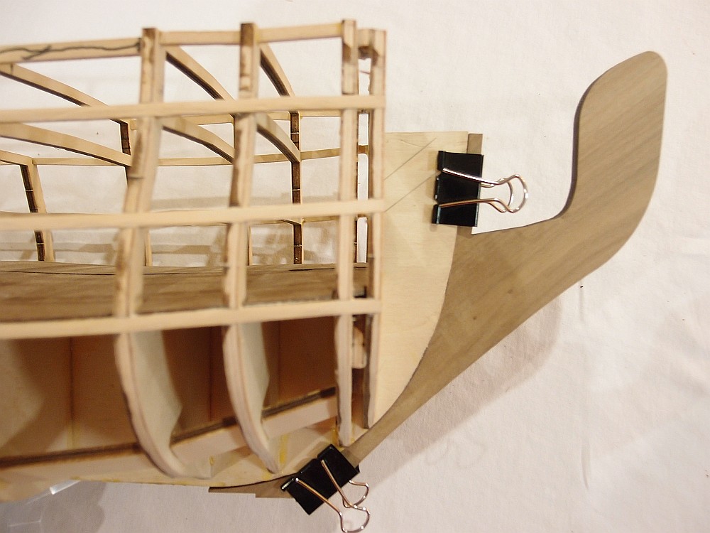
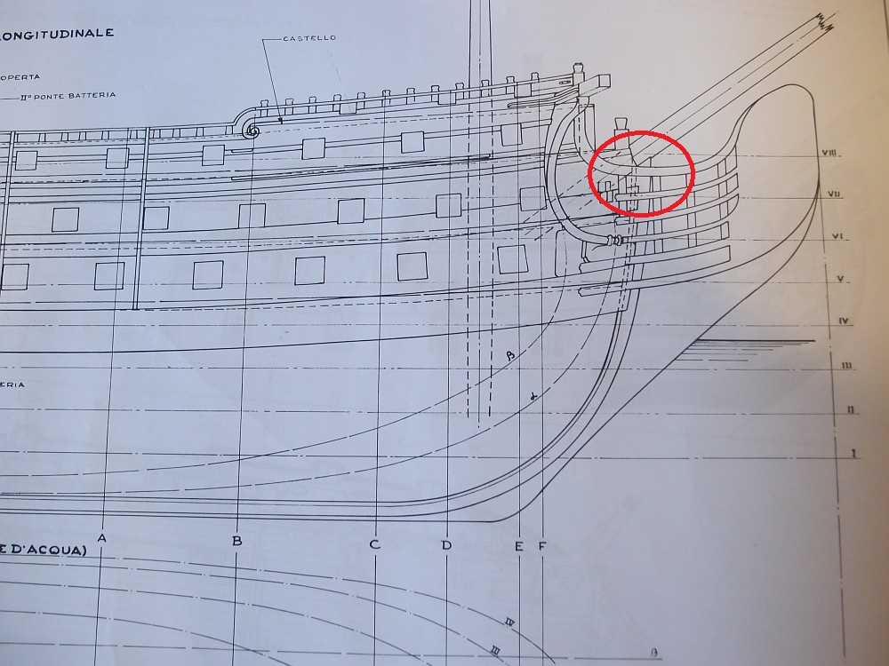
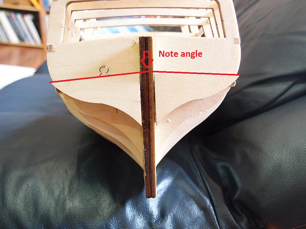
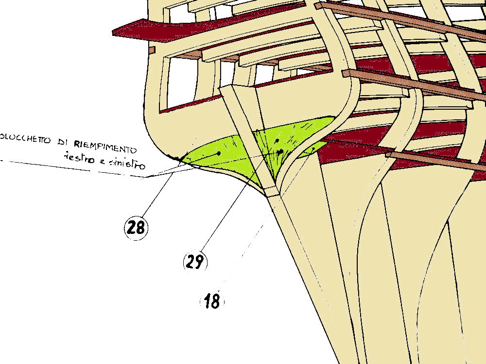
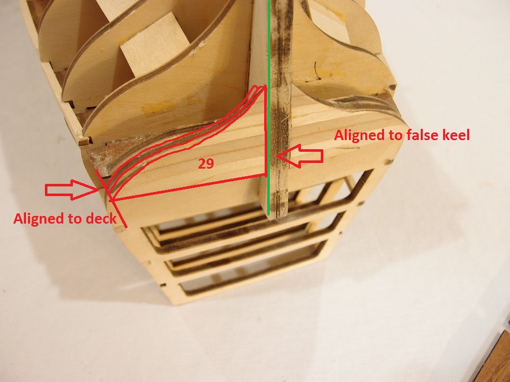
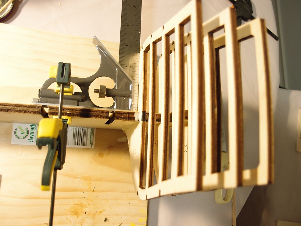
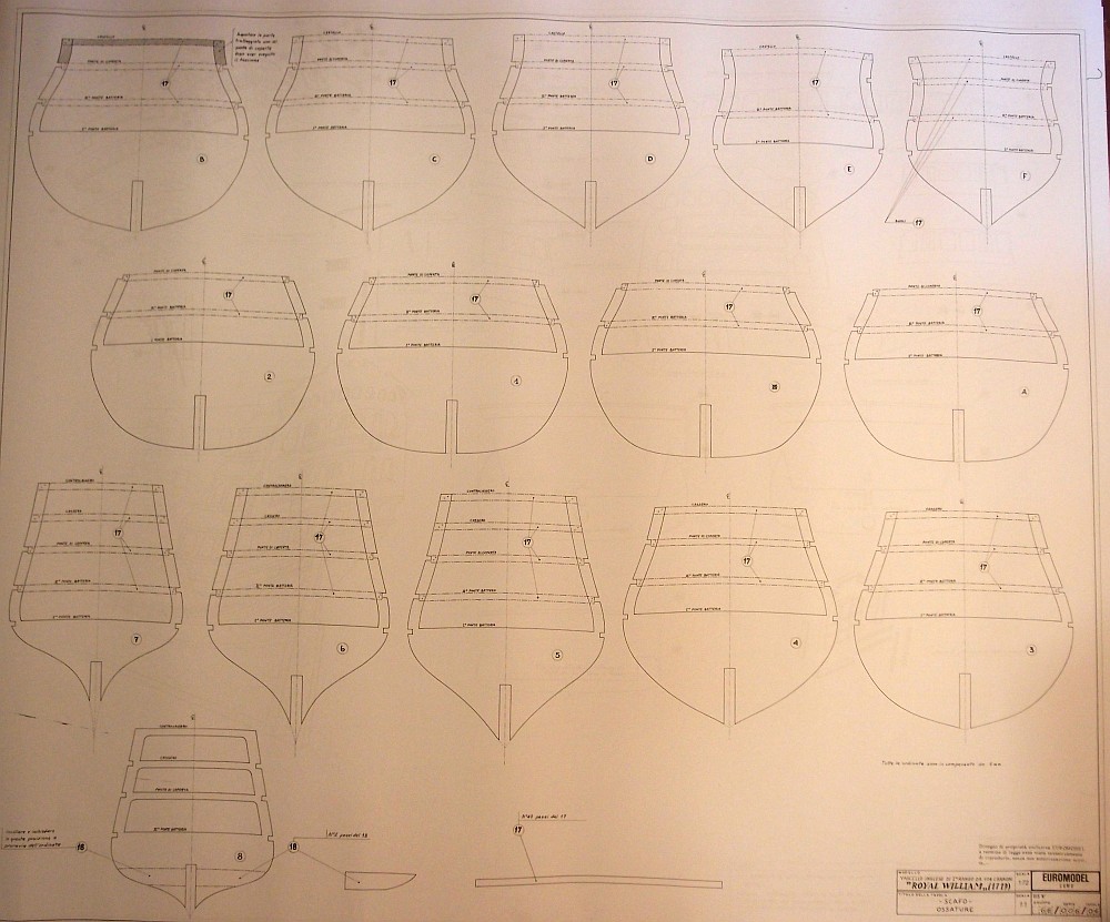
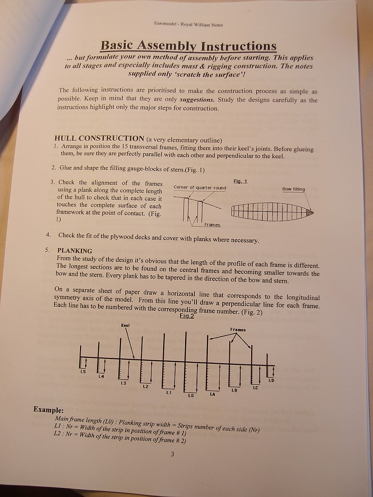
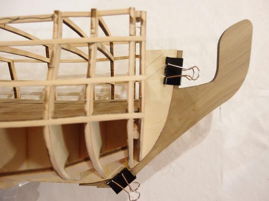
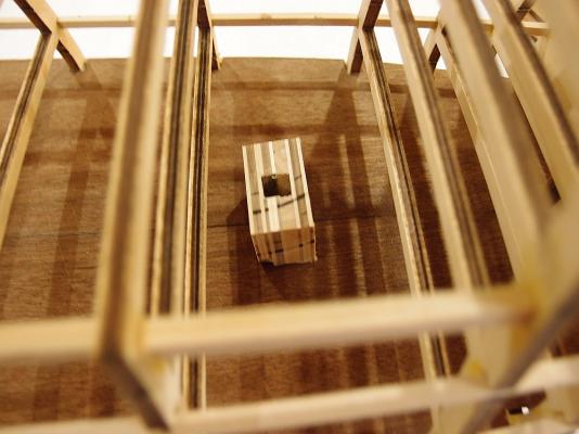
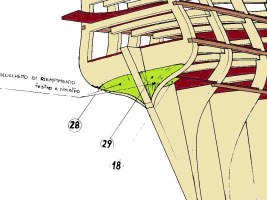
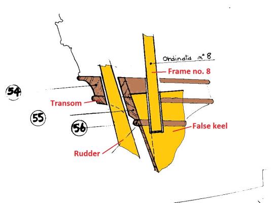
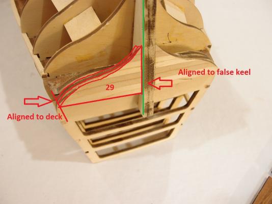
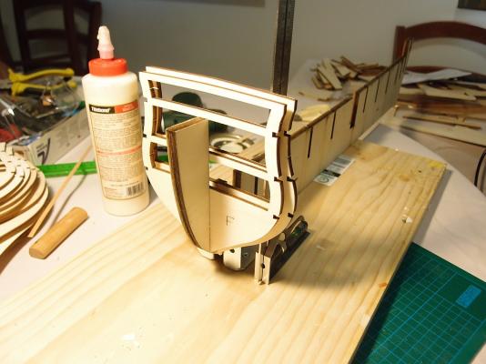
Thanks Mark, Brian, Richard, Mike, and Belinda. Brian, did you encounter the same problem with Frame "F" that I described? Anyway, with that in mind, I did more work today. The Frame "F" thing made me suspect that Euromodel is no Model Shipways, where things simply fall together precisely with minimal fuss. I became even more vigilant for kit errors - e.g. holes or notches cut in the wrong spot, etc. Every move was triple checked with the plans and other build logs. I soon came across this problem: How do I align the rear planking supports (Parts no. 28 and 29) with regard to Frame 8? The plans and instructions do not indicate this clearly. This is VERY IMPORTANT because correct placement of this part determines where the planking will terminate below the transom. Furthermore, if the part is placed as the plans suggest, the upper edge of the part describes an angle, as shown in the red line above! When Keith Julier built his RW, on p.34 he says: Did Keith Julier place Part 29 wrongly, leading to a taller transom than provided for by the kit, thus leading to his 2mm surplus? I have coloured in the plans to make them easier to follow. This is what I mean - the plans suggest that the lower edge of Part 29 should correspond with the curve of Frame 8. This was also the approach suggested by Pete in his Interpretive Info, and also followed by VinceP. Another view of the same area (from Plan Sheet 7, again coloured for interpretation) suggests that the transom extends below the level of the top of the false keel, therefore the run of planking should terminate slightly above the bottom of Frame 8. In the end, I decided to align the tip of Part 29 to just below the bottom deck. This means that the lower edge of Part 29 is flush with Frame 8, and the vertical edge of Part 29 is square to the false keel. Time will tell if I have made the correct decision ... if my rear planking looks strange, it will be this that is to blame!

-
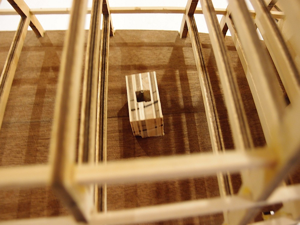
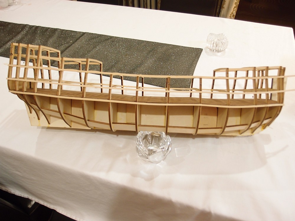
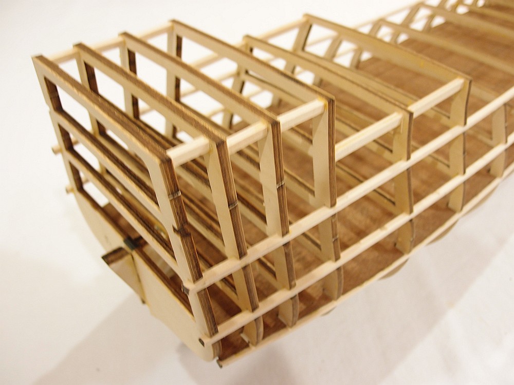
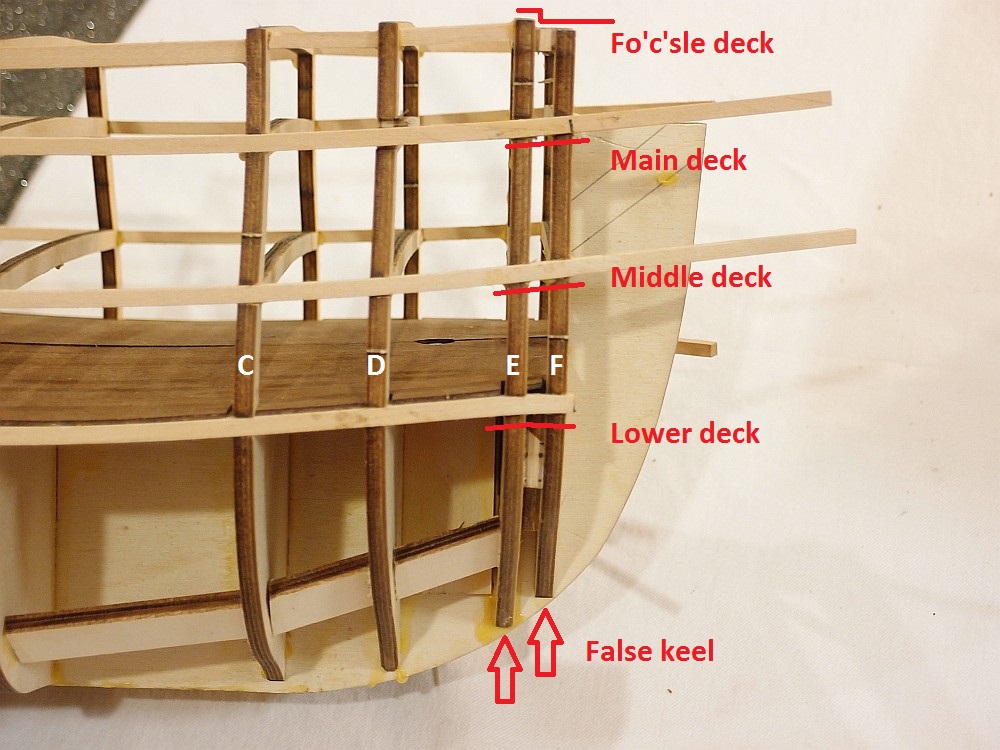
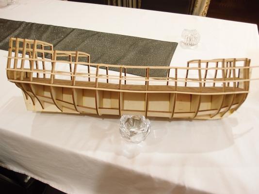
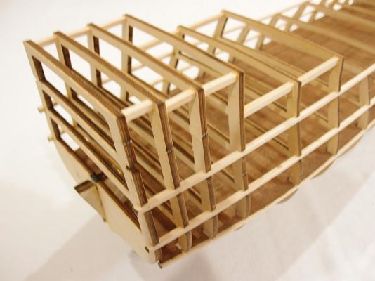
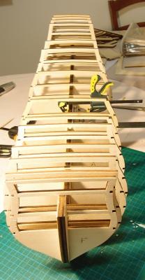
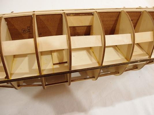
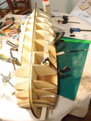
As of tonight, the hull is almost complete and will be ready for planking in a couple of days. I still need to shape the stern and bow fillers and bevel the bulkheads. I installed additional reinforcements for the top deck bulkheads. The frame is now incredibly rigid. I thought I would draw attention to a problem with bulkhead "F". I am not sure if other RW builders encountered the same problem as me - none of them have mentioned it at least. Note that bulkheads E and F are correctly installed with respect to the false keel. Also, the stringers for the main and middle deck run straight and true - they are so perfectly aligned that they simply fell in! Yet, bulkhead F has a pronounced 1mm step at the level of the fo'c'sle deck, AND the lower deck stringer is bent downwards. The exact same problem is present on the other side, so it's not as if I installed bulkhead "F" at an angle. Did any of you have this problem?

-
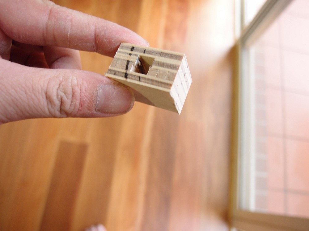
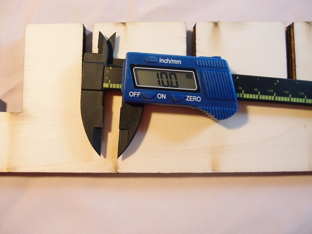
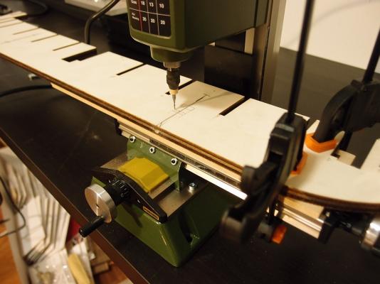
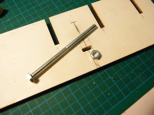
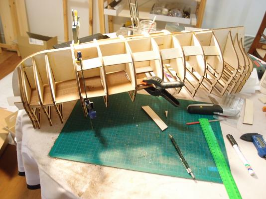
Yes Brian, it would appear that there are some differences between your kit and mine. By the way, I joined a local woodworker's club (here's a shout out to Waverley Woodworkers Club) so that I can have access to their tools ... and what a collection they have! The WWC is more set up for people who work with larger scale projects, so all their equipment is full size. Their lathe is large enough to turn bowls, for example. Otherwise, they have every piece of equipment that we would need - drill press, disc sander, drum sander, belt sander, router, lathes, mills, grinders, polishers, jig saws, band saws, etc. They will save me a fortune on tools, but I would still benefit from miniaturized versions of the above for our hobby. Anyway, I did more work on the boat today. The first thing I did was to lay out all the frames against the plans. In particular, I was looking for the incorrectly labelled bulkheads E and F as noted by VinceP in his build log. Sure enough, as he described, on Plan Sheet 4 the drawing shows correct placement of the bulkheads, but the labels for E and F are the wrong way round. Importantly, the bulkheads themselves are correctly labelled. As noted elsewhere, the RW bulkheads are named according to ship builders convention, as follows: (STERN) 8 - 7 - 6 - 5 - 4 - 3 - 2 - 1 - 0 - A - B - C - D - E - F (BOW) The next thing is to drill the holes in the false keel for future attachment of a stand. The drill press at the WWC came in handy. I drilled a 6mm diameter hole in the 10mm width false keel - only 2mm of clearance either side! The precision of the drill press ensured that my hole was perfectly centered. The above pictures show me milling a hole to accept the nut. Not pictured are the cheeks that I made to strengthen the weakened keel and to hold the nut in. Start of bulkhead attachment. The bulkheads were attached with the aid of a square to ensure ... squareness. As noted elsewhere, the bulkheads are a rather sloppy fit and need to be shimmed. All the bulkheads have now been fitted. Alignment was checked visually and with the aid of a stringer (not shown). Additional reinforcements were made to ensure hull rigidity. These were made from scrap wood - there is more than enough left over to make these parts! At this point, I chose to install the lower gun deck. This deck has notches for the bulkheads pre-cut, so it made sense to install it to help check alignment. Note that the deck is supplied in left and right halves, but installation is impossible unless it is also cut across the beam (into quarters).


-
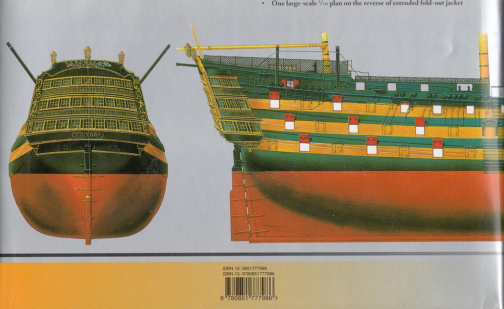
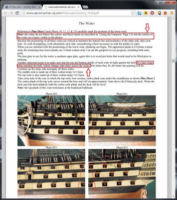
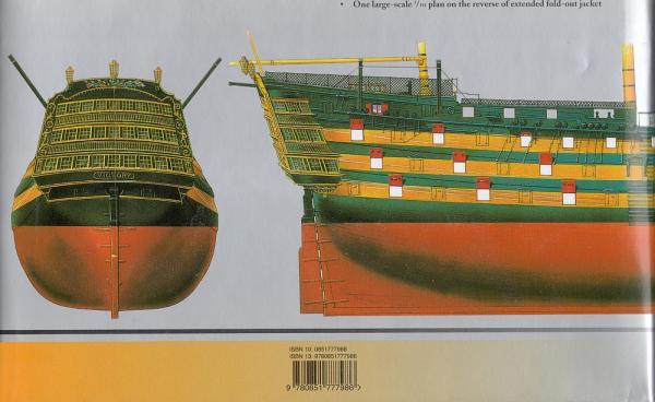
Hi Paulo, just FYI I have attached a screen shot of the Caldercraft Victory instructions. I have highlighted the relevant sentences re: painted lines not matching the wales. You will note that on THIS model at least, the wales do curve up at the rear. The Caldercraft Victory instructions are excellent, I suggest you go there and have a read. (edit) I have also attached a scan of the rear cover of AOTS: Victory, again showing that the run of the wales and painted stripes do not match.
-
The problem with that is that the painted stripes do not match the run of the wales on the HMS Victory in Portsmouth. Any kit which uses contrasting timbers to represent stripes is probably in error. The question is - whether the stripes DID match the run of the wales in Trafalgar, or at any other point in her history. Then again, it's a model. Some choose to be fastidious to history, some choose to have a nice looking model. I definitely lean towards the "nice looking model" camp
-
Paulo I am a far from diplomatic person ... I speak my mind But in this case, I really DO believe that it's your model, and you can do as you wish. I'll only pull a frown if you paint it pink and orange.
-
HMS Royal William by kay
Keith_W replied to kay's topic in - Build logs for subjects built 1501 - 1750
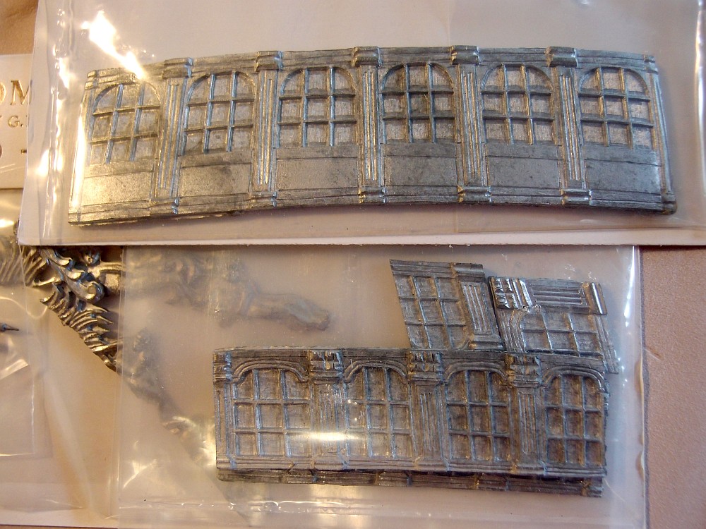
Simply superb. I am starting off with the Euromodel kit of the same. Your work is simply inspiring. I would like to replace some of the metal castings with scratch built parts. If you could post some details on how you made these parts (e.g. the window frames), I would be very grateful. -
She's your model, you can do as you like! There are superb examples of painted and unpainted Victory's around. If you want to be true to the original in Portsmouth, then you can paint it. But remember, before she was painted ... she was unpainted
-
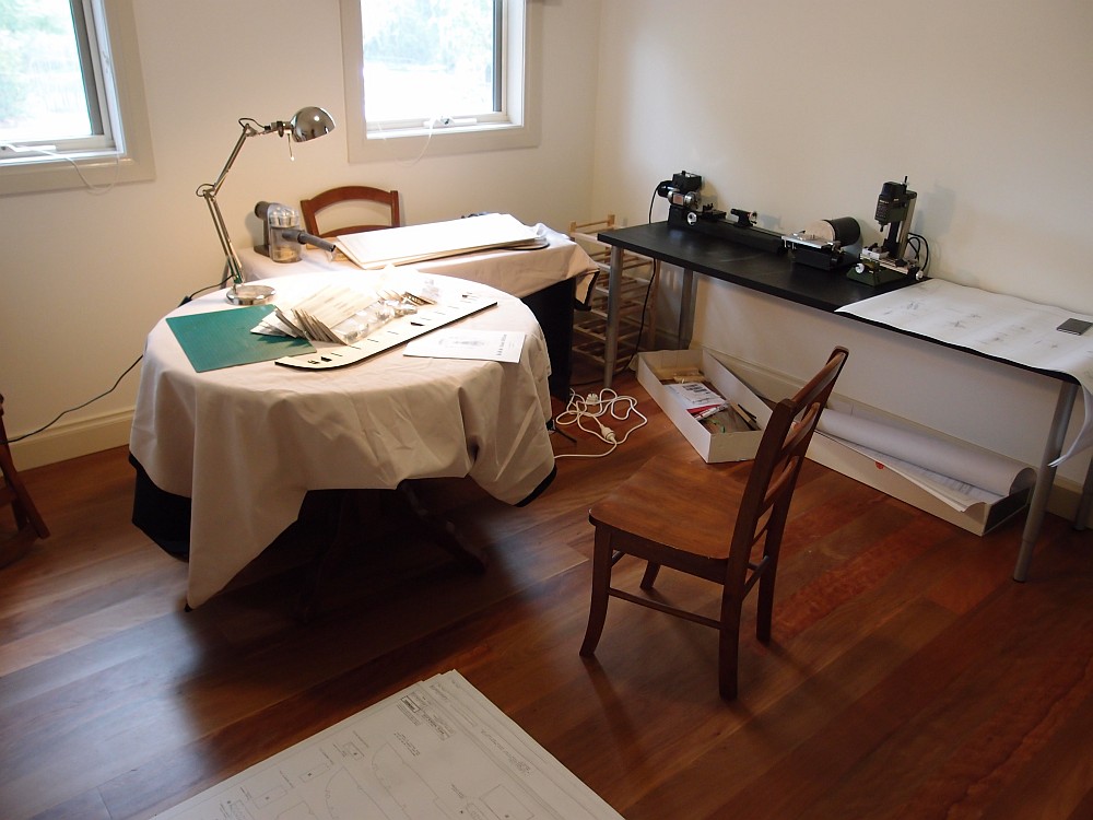
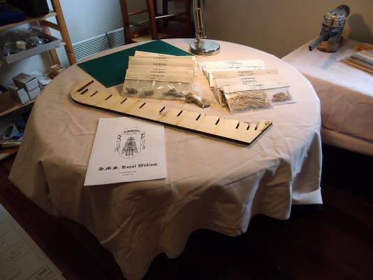
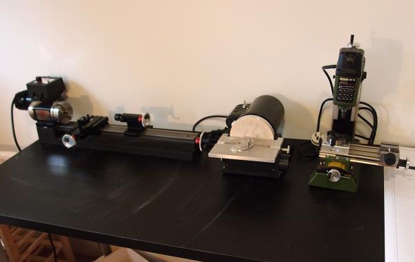
My kit room has been tidied and prepared for the new build. It won't look as neat as this for another three years. Let's go!!! The room has been re-arranged with the power tool bench behind me, and the main modelling table in front of me. All I need to do is turn around to have access to power tools. The desk by the window is where I will do all the Dremelling. Not pictured is my new shelving unit where all my tools, paints, and glues are neatly stowed away. Also not pictured is the clipboard where the plans will be displayed. The main modelling table with the modelling lamp. You can also see my handheld vacuum which is vital for keeping the peace in the household. The tool bench, from (L-R): Sherline 4410 Lathe, Byrnes Disc Sander, Proxxon MF70 mill.

-
Reserved (3) for future update.
-
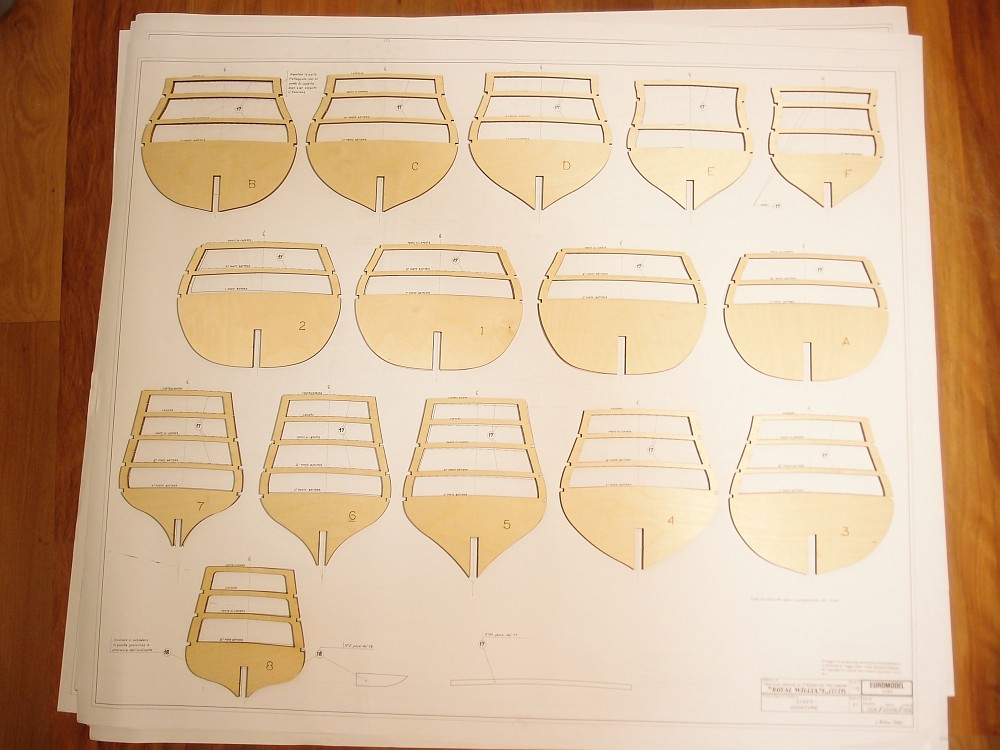
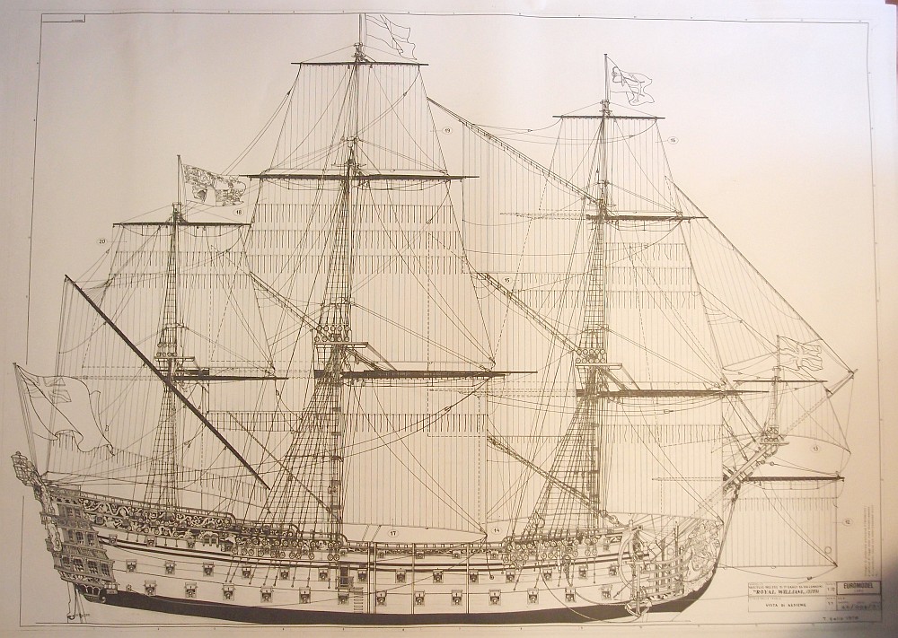
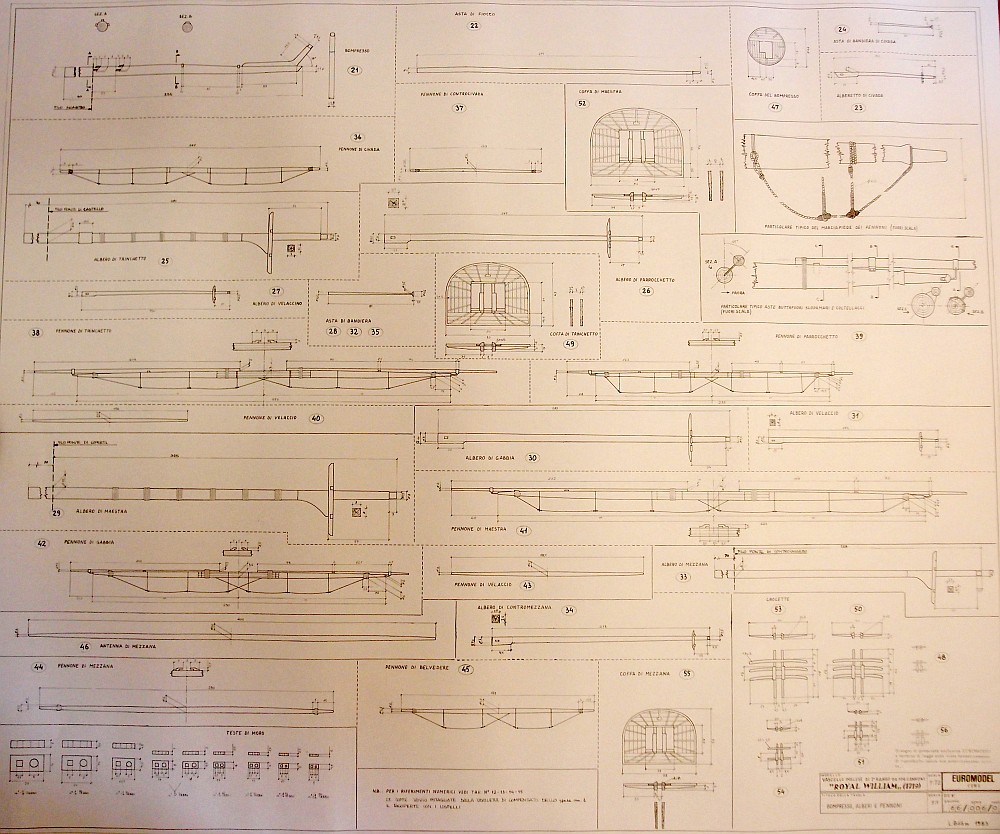
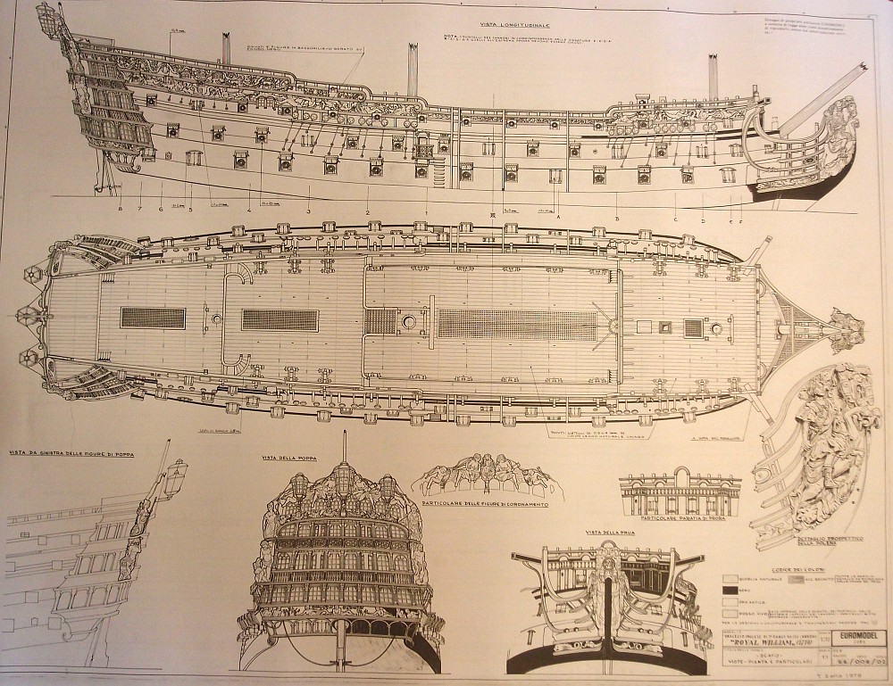
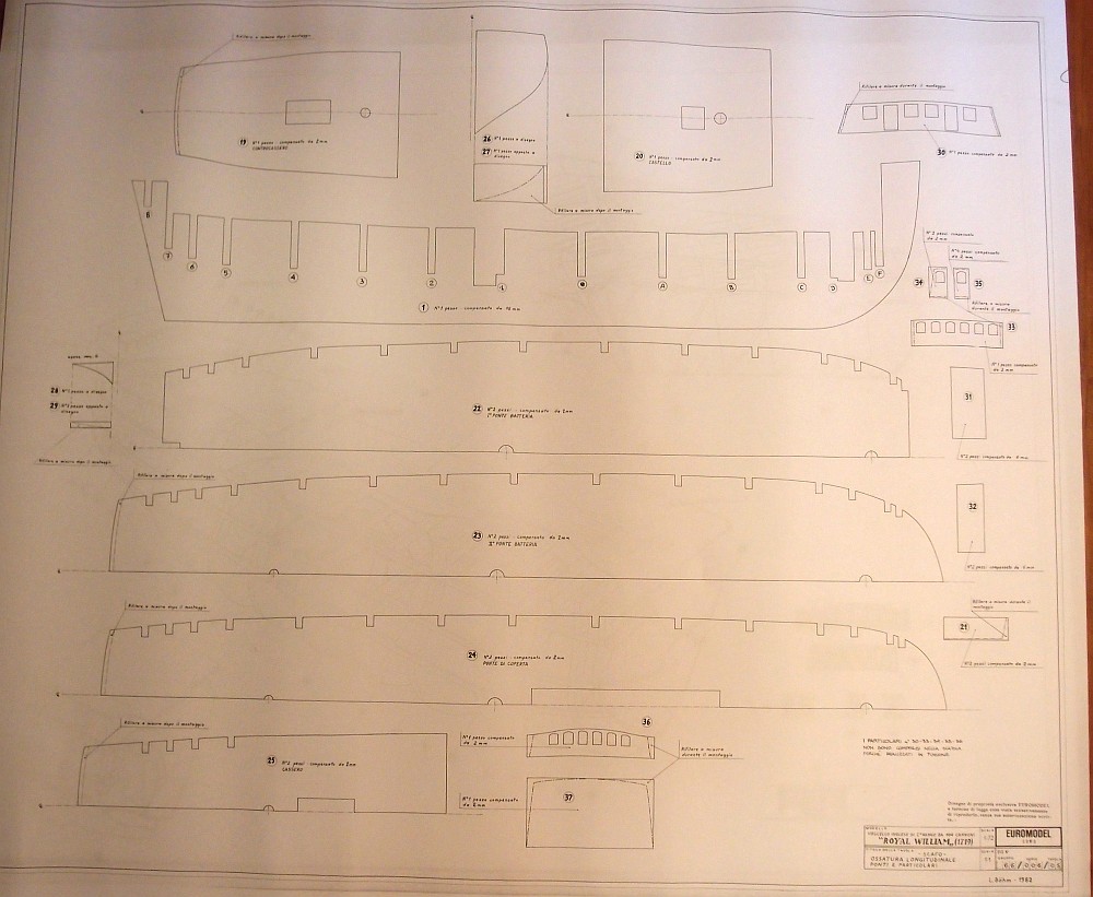
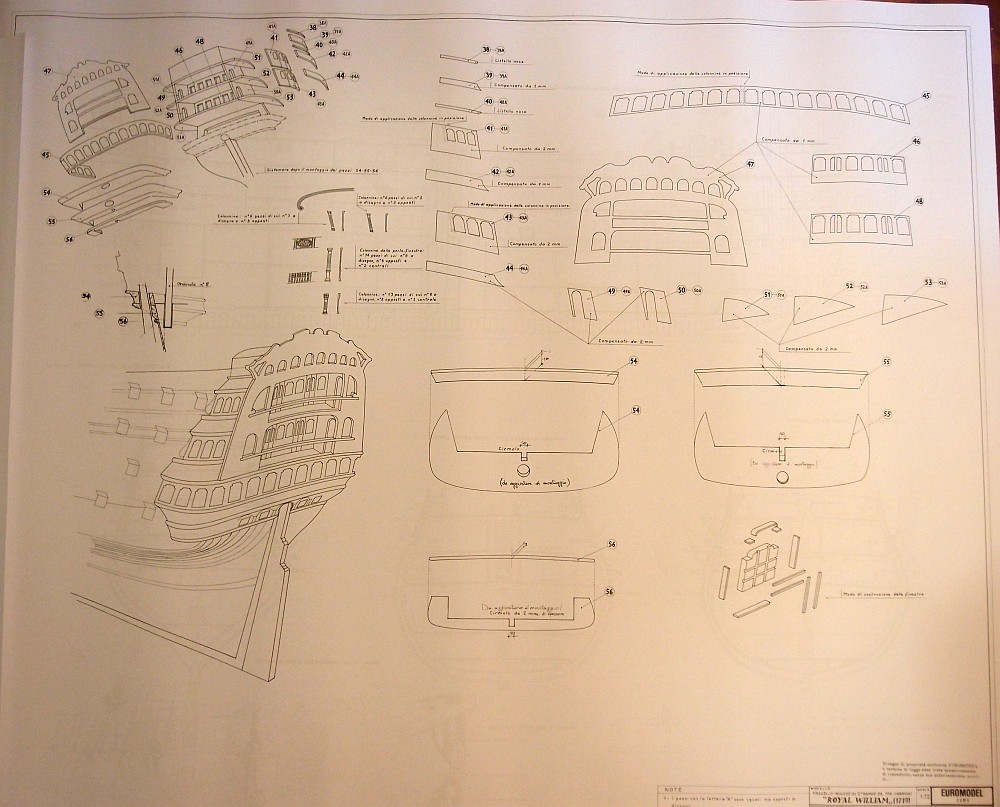
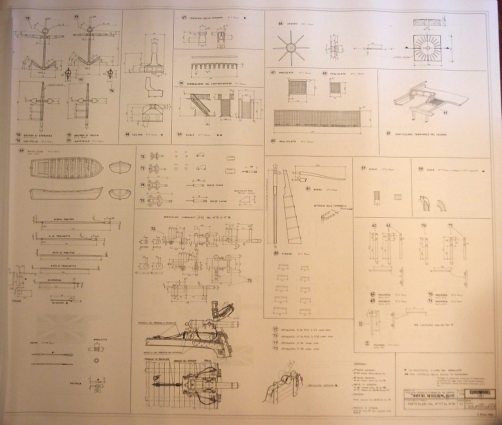
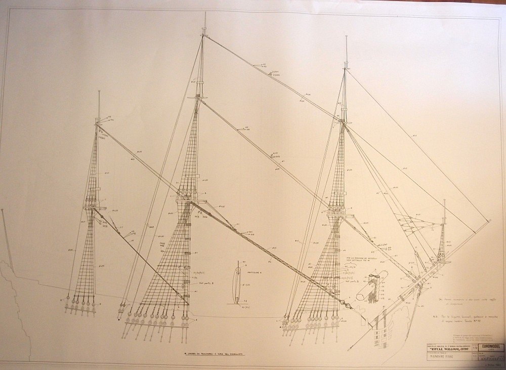
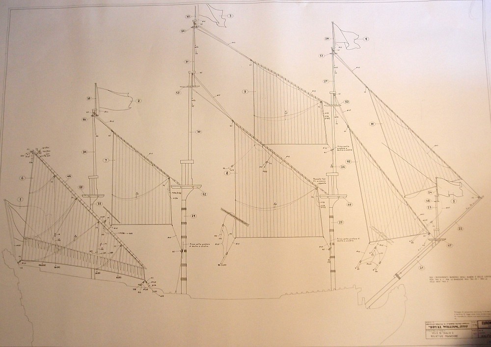
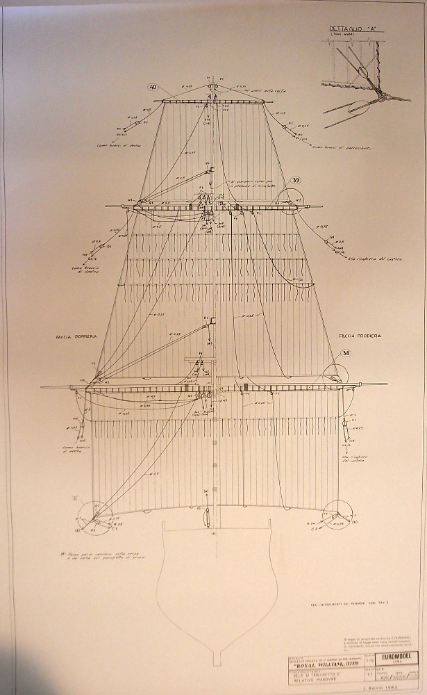
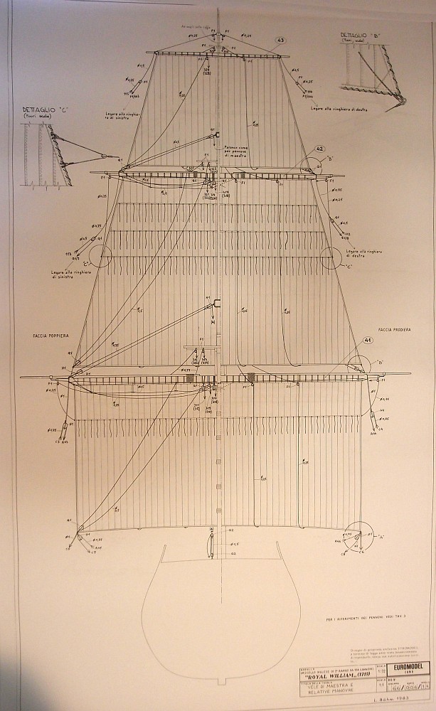
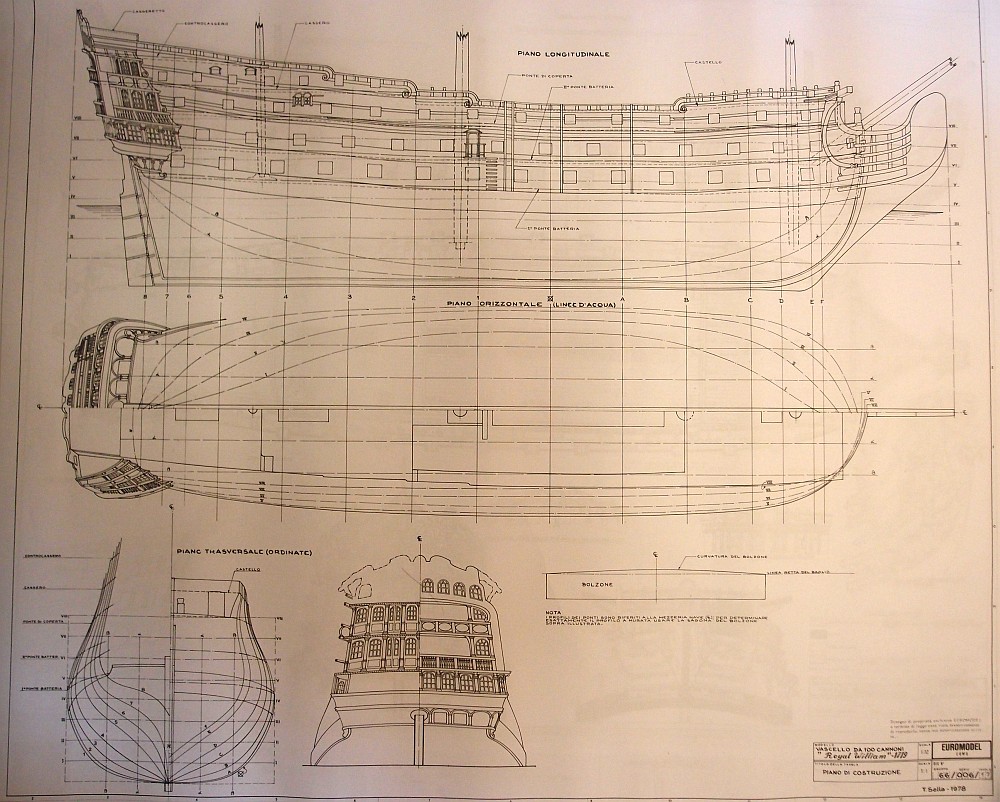
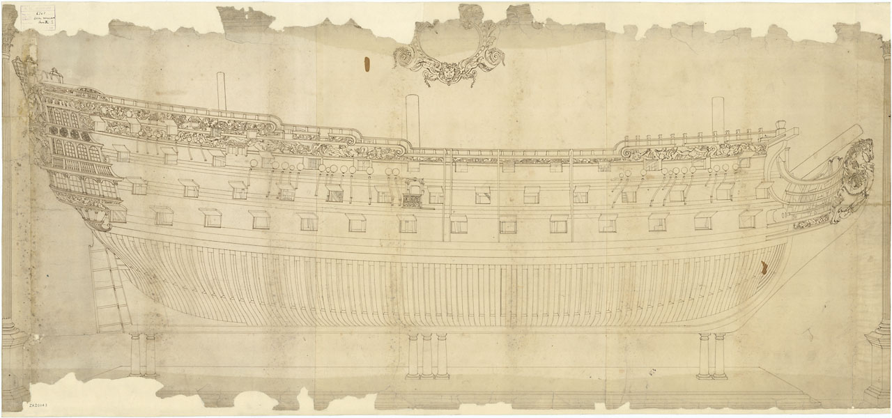
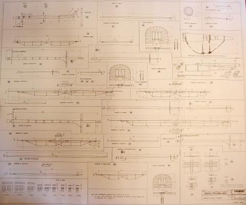
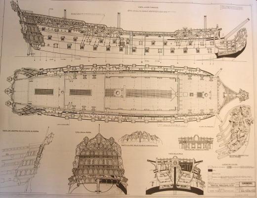
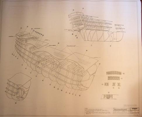
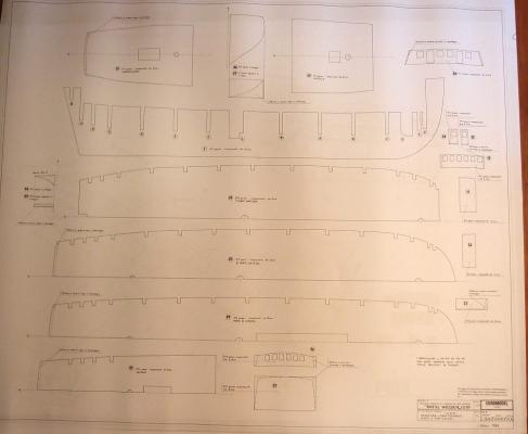
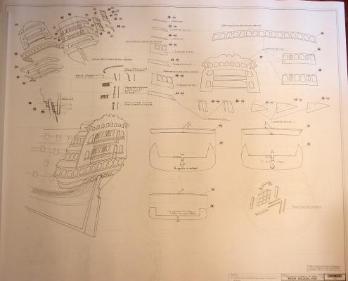
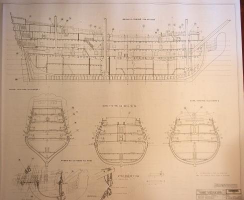
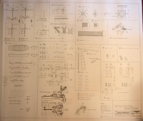
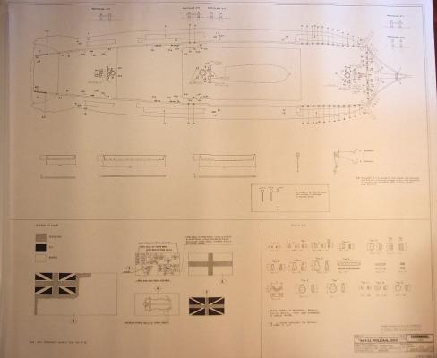
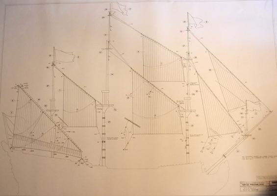
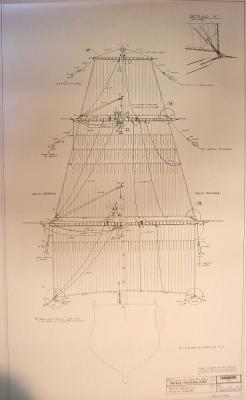
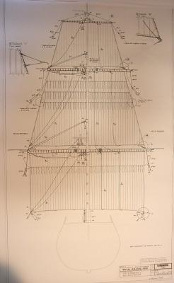
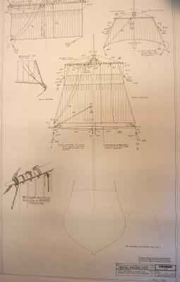
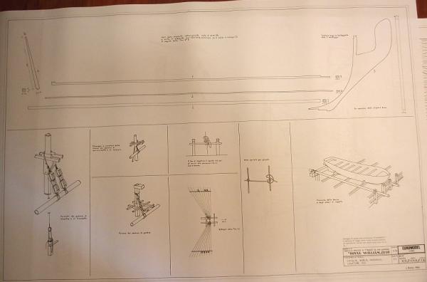
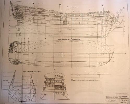
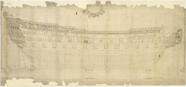
INDEX OF PLANS Sheet 1: Overview of ship Sheet 2: Masts and Yards Sheet 3: Decorations Sheets 4, 5, 6, 7: General construction details Sheet 8: Longitudinal and Cross section (for scratch builders) Sheets 9, 10: Deck furniture Sheets 11, 12: Standing rigging Sheets 13, 14, 15: Running rigging Sheet 16: Mast and yard details Sheet 17: Ships plan


-
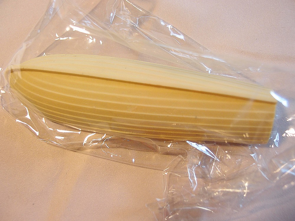
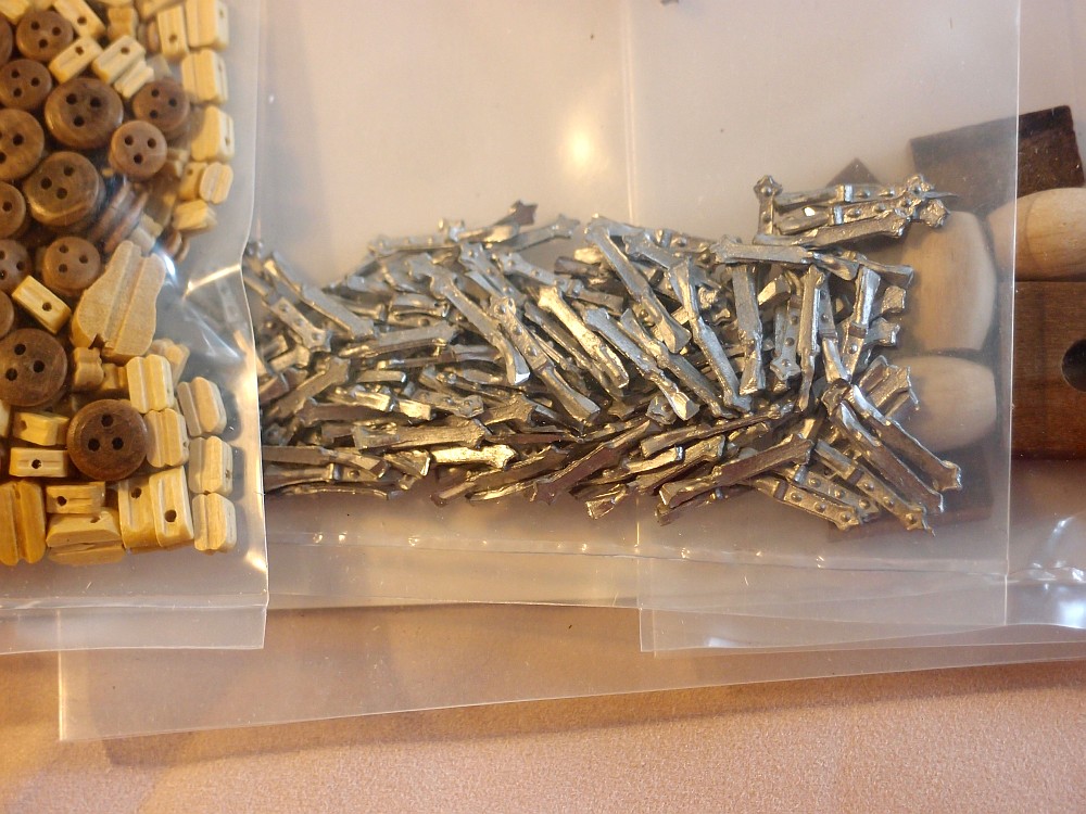
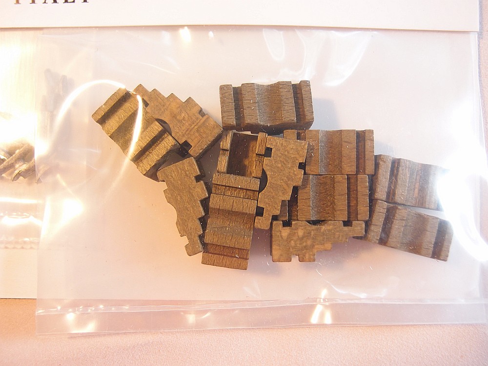
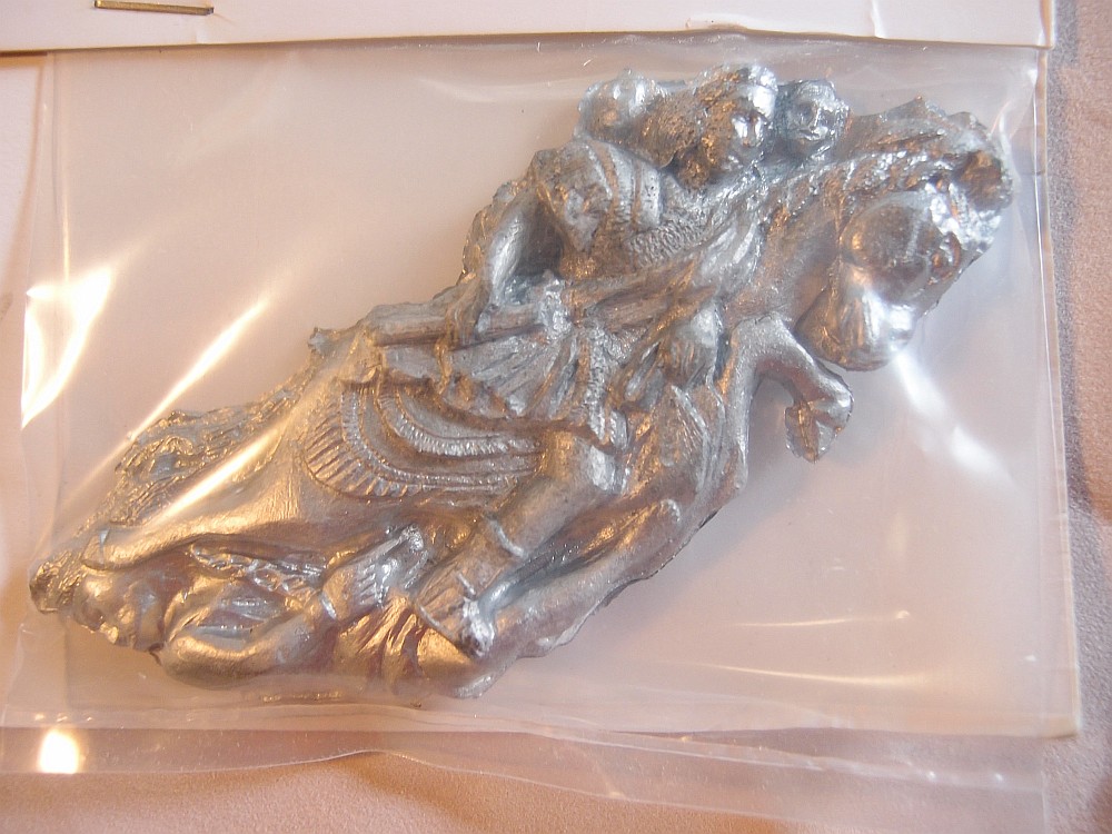
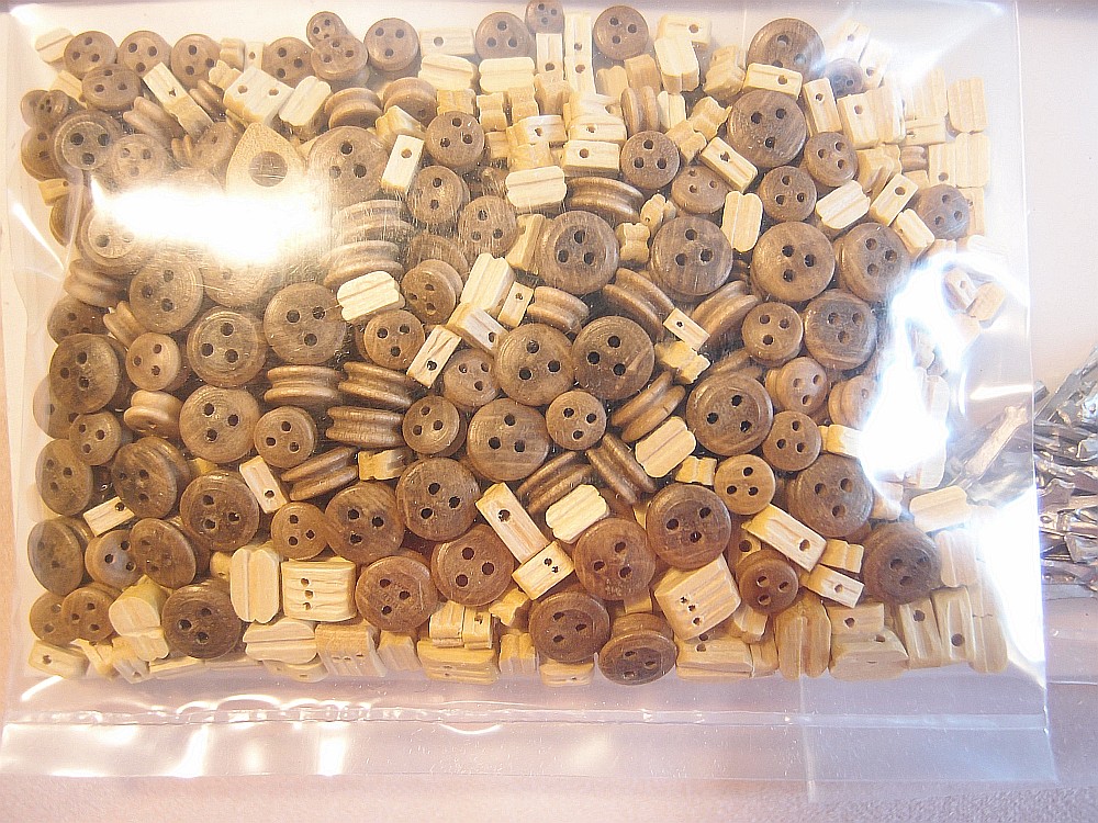
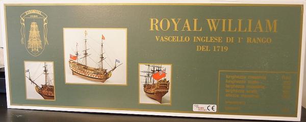
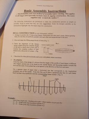
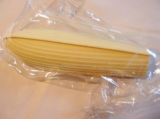
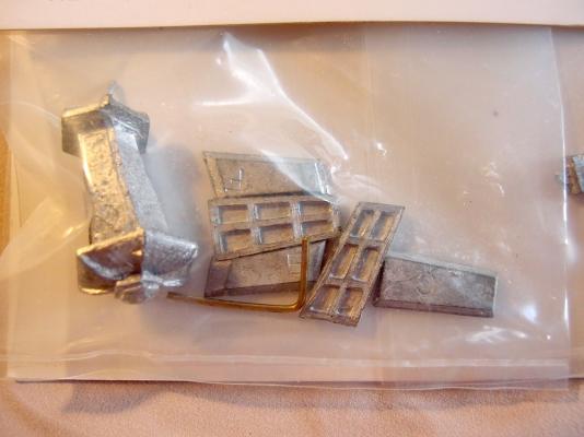
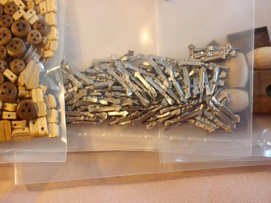
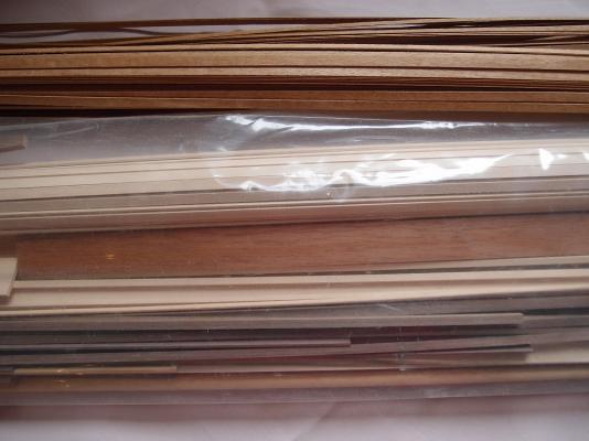
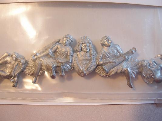
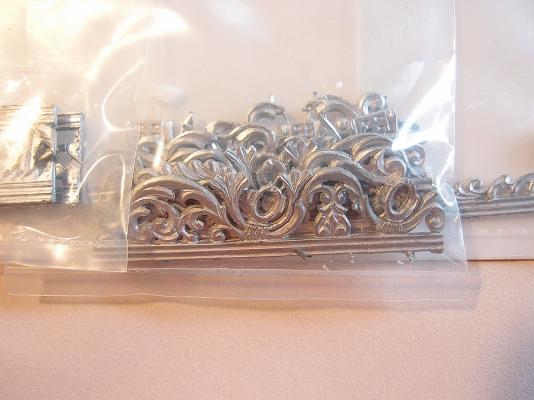
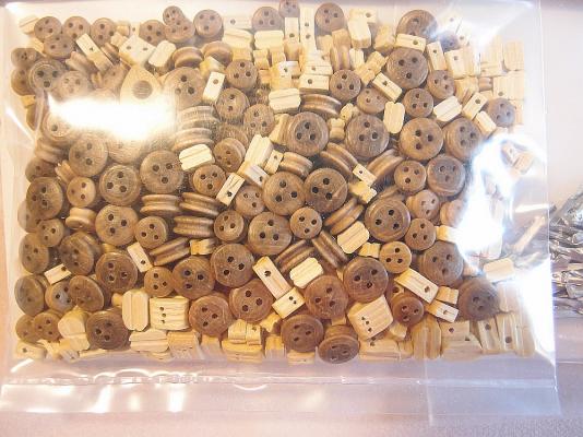
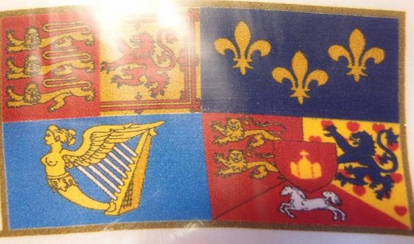
OVERVIEW AND GENERAL KIT IMPRESSIONS The box is really large and heavy, and arrives absolutely packed. Every bit of spare space is taken up by ... peanut foam. I filled up a plastic bag full of these annoying things and was able to get at the kit. First, the bad: The instructions are not very good (to say the least). For a kit of this complexity, the rather thin instruction booklet only contains THREE pages of instructions, of which the first page is taken up by the history of the ship, and some congratulatory notes. This shot is of the second page, and contains nothing that no experienced modeller wouldn't know. OTOH the plans (see next post) are excellent, however many diagrams in the plans could have been printed on smaller pieces of paper and bound in a booklet instead. As it is, all 17 sheets of plans are too large, unwieldy, and hard to find - which is why I took the trouble of making an index for myself (and for others who may follow). The ships boat is a cast resin item. Whilst it is well cast, other kit manufacturers are offering plank-on-frame boats. Oh yes, only one boat? For a first rate ship? Some of the castings are not very good. Look at how chunky this window is. This will have to go into the bin - I can only hope my skills are up to making a replacement from scratch. Likewise, the ship's lantern is a clumsy looking affair. These are meant to be gunport hinges. And these are meant to be gun carriages! The flags are printed on cloth. I am a little indifferent to the quality of the printing. However, the wood is of decent quality. On some older RW kits, the masts are pre-tapered. On this brand new RW kit, fresh from Italy, the masts are not. No matter, I have a lathe! The bulkheads are unbelievably thick and sturdy - 10mm thick! Some other castings, like the figurehead, are excellent. And so are the castings for the stern decorations. ... and the side decorations. The blocks are probably the best I have ever seen included in a model kit. Unfortunately, they are all mixed up in a bag. I will have to carefully sort them and put them away.


-
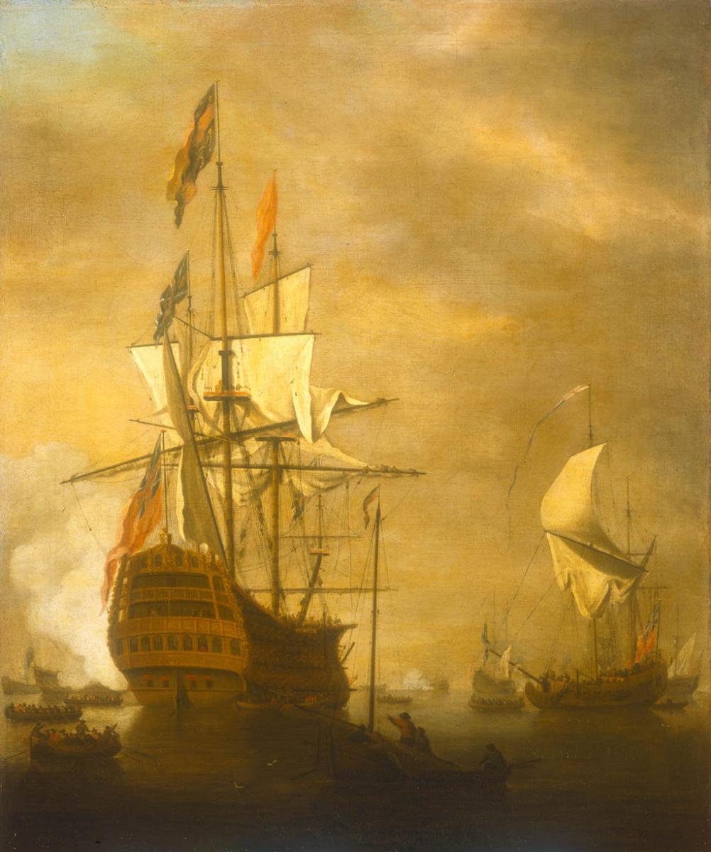
Thanks for visiting my build log. The first few posts will be updated as I go along From Wikipedia: HMS Prince was rebuilt by Robert Lee at Chatham Dockyard in 1692, and renamed at the same time as HMS Royal William. During the War of the Grand Alliance the ship saw action at the Battle of Barfleur of 19 May 1692. The Prince belonged to the red squadron and carried the flag of Rear Admiral of the Red Sir Cloudesley Shovell. She was the first ship to break the French line during the battle. Later she was rebuilt for a second time by John Naish at Portsmouth Dockyard from 1714, relaunching on 3 September 1719. She was laid up after her re-launch and saw no service at all until she was reduced to an 84-gun Second rate ship in 1756. One year later, she was part of an unsuccessful expedition against Rochefort led by Admiral Sir Edward Hawke. Her squadron, under Vice-Admiral Charles Knowles, attacked the Île-d'Aix and forced her garrison to surrender. In 1758 she participated in Boscawen's and Wolfe's attack on the French Fortress of Louisbourg (Nova Scotia) and an indecisive skirmish with a French squadron. The following year the Royal William returned to Canada under the command of Captain Hugh Pigot to join the attack on Quebec. After the Battle of the Plains of Abraham and the capture of Quebec she sailed back to England with the body of General Wolfe. In 1760 the Royal William was Boscawen's flagship when he took command of the fleet in Quiberon Bay. However, after a severe gale he was forced to return and shift his flag to the Namur. During the expedition against Belle Île of 1761 she was detached with several other ships to cruise off Brest and prevent a French counter-attack from there. The Seven Years' War seems to be the last time that the Royal William played an active role. She was broken up in 1813. LINKS TO RESOURCES Euromodel website - Royal William Product Page - Interpretive Information by PiratePete - Royal William Resource Information Build logs on MSW - Royal William by VinceP (Euromodel) - Royal William by Brian C (Euromodel) - Royal William by Denis Pink (Euromodel) - Royal William by Ersin Derebek (scratch) - Royal William by Kay (scratch) - Royal William by Marktiedens - Royal William by ken3335 Other resources - USNA model of Royal William - Royal William by Victor Yankovitch, also alternative source.

-
Looks like you found out how to apply a gloss finish after all! What method did you use? She looks great!
-
Lol, I heard a rumour that you had bought one! A little bird told me! I received my Royal William a couple of weeks ago. Just waiting to complete my current model and then move on to this. I might give you a head start, so that I can learn from your mistakes!
-
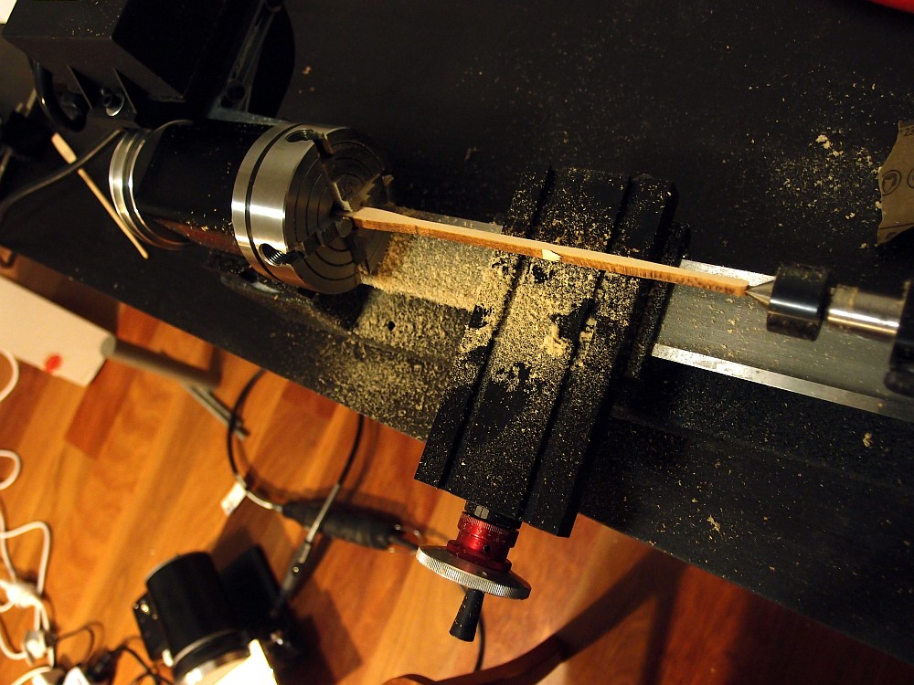
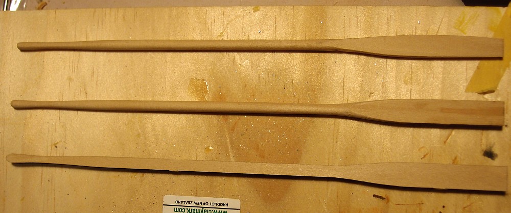
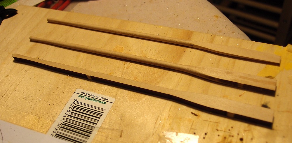
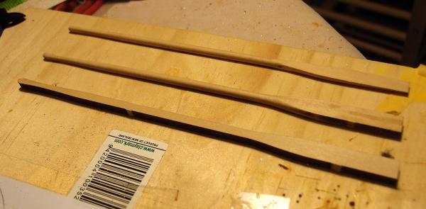
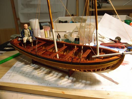
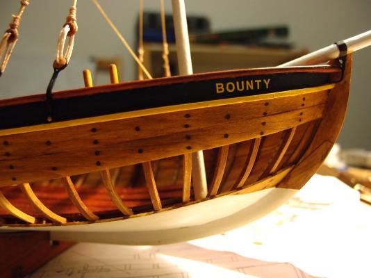
After a few months hiatus from modelling I am back, with some new toys to play with. First, my new lathe - a Sherline model 4410. Here it is pictured with the optional 4 jaw chuck, holding an oar: Here are some oars. The from bottom to top: cut from the kit, (middle) after turning on the lathe, (top) after being sanded down with my new Byrnes disc sander: And finally, a picture of my model as of right now. Note that I have added BOUNTY lettering to the prow of the boat: I have to finish this model - it is taking way too long! And I have to make room in my modelling space for my next project, WHICH HAS FINALLY ARRIVED!!!!!!! I am excited and intimidated at the same time. Watch this space for a new build log very soon!


- 78 replies
-
- 13
-
-
- model shipways
- bounty launch
- (and 1 more)
-
OcCre planking system
Keith_W replied to hamilton's topic in Building, Framing, Planking and plating a ships hull and deck
Hamilton I think that the notches are there to help stiffen the bulkheads before you start planking. -
Superb work! I admire your persistence. You really get a feeling for the Vikings with your model.
-
Nigel, I have been patiently waiting for your tutorial on deck caulking and planking. Have I missed it, or have you not posted it yet?
-
THE BLACKEN-IT TRIALS
Keith_W replied to Erebus and Terror's topic in Metal Work, Soldering and Metal Fittings
Fantastic work, thank you!! The mods should consider making this a PDF and moving it into the articles section. -
I would definitely prefer more bulkheads. But more bulkheads come at a cost too - they need to be carefully positioned otherwise it would be difficult to cut out some gunports!
-
Yes Nigel, I have been following your Mordaunt build log and I was impressed by your planking. If you could post a tutorial, I would be really grateful.
-
Hi Nigel, it is hard for me to see what you are going to do here. You have obviously taken a lot of trouble to get the frames accurately cut. I presume you are not going to cover it all up with planking? That would be such a waste!