Thistle17
-
Posts
1,054 -
Joined
-
Last visited
Content Type
Profiles
Forums
Gallery
Events
Everything posted by Thistle17
-
 Hey there. In this world of plank on bulkheads and frame it is refreshing to see a solid hull model come to life. That is where I began my journey into ship models. I am intrigued by the assembly methodology so have signed up to track your progress. I am curious about the hull line shown above. Is that the waterline? Joe
 -
Adapting DRO Devices To Shop Tools
Thistle17 replied to Thistle17's topic in Modeling tools and Workshop Equipment
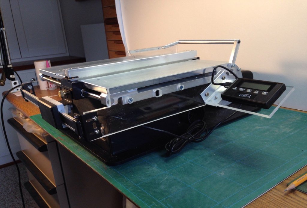
In the interim, as I await a response from Anytime Tools I am sharing my rendition of mounting the IGAGING Linear Scale to the Byrnes Saw. I had examined other ways of adapting the device to the saw and ultimately returned to a methodology of the earlier rendition posted on MSW by another member. It was sound to use the saw table top as the datum for mounting the device. It serves as an alignment measure for the height, parallelism and distancing references needed to enable easy alignment, mounting and "loading" of the inboard saw fence "carrier". I chose readily available materials, that were easily machined and light in weight. All mounting utilized is common #8-32 hardware. The other factor in choosing this methodology was "do no harm" to the Byrnes saw. There are just a few modifications I would make to my current version: 1. Pad out the plexiglass mounts to "buy back" the 5/16" lost in fence excursion. This is related to the IGAGING electronic enclosure interference with the rail mount of the saw. 2. Instead of chamfered #8-32 mounting holes to attach the plexiglass supports to the aluminum saw mount I would make them countersunk loose fit clearance holes for easy alignment (parallelism) of the supports to the front and top of the saw table. 3. I had on hand 1/2 X 1 X 1/8 inch aluminum right angle. I would use 3/4 X 3/4 X 1/8 inch and eliminate the machining of the "port" bracket for interference of the belt shroud. 4. Depending on which unit anyone settles on the display mounting may need some consideration in that some units come with the swivel arm mount and some do not. Or maybe it is just a case of "as you like it". 5. If it is mounted as shown I would be very inclined to shorten the interconnect cable and shield it. 6. I had originally intended to use rare earth magnets to attach the "Z" bracket of the unit to the fence traveler but I have since noticed that there is a bit of play (in the "X" axis) using the knurled lock down nut as a securing method. 7. This is just an acknowledgement item. One can still get a 3/8" open end wrench in the belt shroud to hold the outboard height lock down but it would help if one that is a bit longer than the normal 3/8".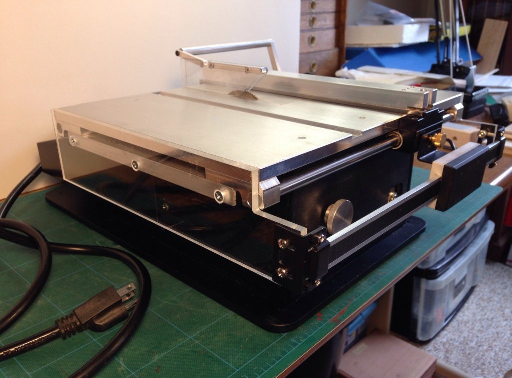
-
Adapting DRO Devices To Shop Tools
Thistle17 replied to Thistle17's topic in Modeling tools and Workshop Equipment
Your right Mark, truly you are? I will have to keep that in mind as I progress. Last eve I received an e-mail from Any Time Tools regarding a query I sent into them with the data above. They returned an answer I somewhat expected. My unit has been discontinued. They are recommending another unit but it seems to have the accuracy of mine. So I am back at them to get to the bottom of it all. The one on their site is out of stock but has a 4 X accuracy or so they say. In retrospect I should have set up a "lab" experiment to evaluate the DRO unit prior to "tricking out" my saw. I had erroneously assumed that it had performance matching my digital calipers (a Harbor Freight Saturday Night Special) which demonstrates good accuracy and repeatability. One lives and learns! Joe -
Adapting DRO Devices To Shop Tools
Thistle17 replied to Thistle17's topic in Modeling tools and Workshop Equipment
Bruce you make a good observation. I will rerun the experiment using your suggestion to reduce/eliminate possible blade flex. Since yesterday I tried to order a new unit and they are out of stock so this may be an extended saga. In the process of this experiment I have to admit that I may be taking this a bit far as I wonder just how much one needs .001 accuracy to make model ship parts? Joe -
Adapting DRO Devices To Shop Tools
Thistle17 replied to Thistle17's topic in Modeling tools and Workshop Equipment
With the exception of the first reading it appears to fall within the advertised accuracy (.004") but the repeatability ranges from - .0035" to +.0035". At this point I am thinking I will purchase the newer aluminum unit and retry the same experiment. Standby. Joe -
Adapting DRO Devices To Shop Tools
Thistle17 replied to Thistle17's topic in Modeling tools and Workshop Equipment
I continue to evaluate the performance of the IGAging Linear Scale. For the past few days I have been observing some unexplainable deviations from what I expected in terms of repeatability of measurements. In trying to calibrate the fence settings I was using my wood shop brass gauging blocks (the square ones that are graduated from 1/8 to 1/2 inch). I was using the 1/2 inch one primarily and I was getting results that were way off (.010 deviation or more). I finally took a square to the brass bar and found it had a bow in the middle of the used face giving me the varying deviation. So I switched to the 3/8 bar and measured it at .3755" on my digital caliper (advertised accuracy .001"). In 10 consecutive measurements (blade set low, fence moved against blade and zeroed out on the DRO, fence moved past 0.0375 and then moved in against the brass bar) I got the following DRO readings: Test Reading Deviation H/L Pwr On 1 0.384 0.0085 H 2 0.378 0.0025 H 3 0.374 0.0015 L 4 0.379 0.0035 H 5 0.375 0.0005 6 0.375 0.0005 7 0.374 0.0015 L 8 0.375 0.0005 9 0.373 0.0025 L 10 0.372 0.0035 L -
There is an excellent reference in the magazine "Fine Woodworking", Tools & Shops", Winter 2019 on pages 80-86. It speaks to products and techniques for rust removal, prevention and maintenance. If you can't obtain it in the library go to Taunton Press, Fine Woodworking.com. Joe
-
Adapting DRO Devices To Shop Tools
Thistle17 replied to Thistle17's topic in Modeling tools and Workshop Equipment
I will be supplying photos soon. My only timidity is related to the actual device, not the mounting methodology. I am still evaluating the performance. I have no affiliation with the IGaging folk or anyone else that resells the product. I just want to be sure it is worth the trip. I hope you understand. I went through 3 iterations of the mounting and ended back where the original MSW member started with his mounting system. It is just a bit more refined I believe. However his approach is the right way to go. In regard to the IGaging device I am thinking I will order a newer version and see if I find the utility and advertised performance works to my satisfaction. Of particular note in the product features it appears that they have slightly changed the functionality by what I can discern from the web site images. Mark the repeatability is one area I am addressing. At first blush I am not too impressed with mine. It does not have an ABS(olute) function on my vintage. It has a Preset and INC(rement) function. The newer ones have the ABS function. Strangely "sometimes" my unit holds the measurement I dialed in when power is turned off and then on. It doesn't seem to hold the same (actual) displacement dimension when I move the fence however. These are the kind of performance anomalies I am addressing. Joe -
Adapting DRO Devices To Shop Tools
Thistle17 posted a topic in Modeling tools and Workshop Equipment
I finally have gotten around to outfitting my Byrnes saw with a DRO as a previous member herein had shared. I employed a IGaging 35-712 P of a vintage around 2016. I glean it is an older model as it's accuracy is advertised as .004" vs todays .0015". I have spent a good deal of time learning how these devices work and empirically how they perform. I thought it would be a good "community" repository of knowledge to help others interested in digitizing non DRO machines. There are relatively inexpensive units and of course there are more expensive ones as well. The IGaging company offers product at the lower end in two tiers; aluminum substrate versions and the more expensive stainless steel variety. The price differential is just about 2X between units. The Igaging units are not proprietary as other company's offer nearly look alike product. Also there is an emergence of Bluetooth connectivity and "apps" for some more intelligent display and interactive devices. One has to graduate to the more expensive tier to get at the data output. Many people have used the units on midi mills and the like as they offer an X/Y/Z package. The saw of course only requires one for fence displacement. Using the information located on Yuri's Toys web site one can get a decent understanding of the characteristics (and of course the vulnerabilities) of the devices. Here in brief form is what I have learned so far applying the device to the saw: 1. The accuracy is pretty true to the advertised number i.e. .004 2. Repeatability is somewhat tenuous. 3. The unit functions better when the 6 foot cable is not coiled up. I suspect crosstalk. 4. It is recommended that the USB cable either be cut down or shielded for operation in "noisy' environments. 5. I find that the displacement function i.e. measuring from the saw blade to right or left is all I presently find useful. 6. The caveat is that it must be zeroed every time the fence is moved. So with this beginning can we continue to create a repository of info for application of these devices and log them here? I think it would be of great value to many. Joe -
My new blades arrived and I installed a like for like Thurston I-292 and it works great! So indeed it was a dull blade. And Jim I did not realize they were hollow ground. I should have checked it. Thank you. Joe
-
Opinions on Sherline DRO for Lathe
Thistle17 replied to rtropp's topic in Modeling tools and Workshop Equipment
Ac input 120 -240 VAC, 50/60Hz, 100MA. DC output 9V, 305ma. female micro plug. Joe -
I was speaking with Jim about this very problem just a few days ago i.e. the width deviation. We concluded with the amount of ripping I had previously done my .030 blade had dulled on the fence side. I could observe a slight deflection away from the fence when ripping even 3/64" boxwood and an attendant dragging or binding. It doesn't take much to have this show up even with a very slow feed and the blade just above the work. Oddly, or maybe not so, cross cuts seem to work with out binding. Here the cut is on the outboard side of the blade. I have ordered new blades. Remember these slitting blades have very little, if any, tooth offset and are not hollow ground so there is a side bearing component of load to these blades. Go to the Thurston web site to learn more about these blades. While waiting I have resorted to partial ripping of the stock i.e. running it through without the blade cutting through the surface, turning it over and running it through again. Not preferred but somewhat of a workaround. Joe
-
Ah that passion it does keep the heart beating and blood flowing Bob. I will be following. Joe
- 78 replies
-
- 3
-

-
- medway longboat
- Syren Ship Model Company
- (and 1 more)
-
Now what???? Not only do you execute at a very professional level your productivity is not to be ignored. You profess "slow and steady" so HOW DO YOU DO IT?? This too is a trophy work Rusty! Joe
- 152 replies
-
- 1
-
-
- medway longboat
- Syren Ship Model Company
- (and 1 more)
-
Byrnes Table Saw Tips (requested)
Thistle17 replied to Matrim's topic in Modeling tools and Workshop Equipment
Well Jim Byrnes was kind enough to return my call and after relaying my tale of woe concluded that the likely possibility is that one side of the blade has dulled. So I will order more blades. I will reorder the .03 and the .04 to gauge their effectiveness. Joe -
Byrnes Table Saw Tips (requested)
Thistle17 replied to Matrim's topic in Modeling tools and Workshop Equipment
Mark I had been lifting the blade to just above the thickness of the wood. It is a practice I have long used in the "big boy" shop. I do this for safety and for reduction of the surface area the stock is rubbing against the blade I relooked at the tooth rake of the blade in question this am and it is somewhat off, but close to 90 degrees making me think the tooth is acting more as a "chopper" than a slicer. Extending this thought as the blade cuts (or chops) and heats it deforms away from the stock somewhat causing the stock to widen. This continues until the blade can deform no more as it is stopped by the zero clearance insert. Am I over analyzing this or what? And thank you for reminding of this reference. Joe -
Byrnes Table Saw Tips (requested)
Thistle17 replied to Matrim's topic in Modeling tools and Workshop Equipment
Thanks for your input everyone. As I am driven to get on with my Cheerful I am moving in a few directions while waiting for replies. Even though the stock is only 3/64 box I lowered the blade below a cut through level. Then raised the blade to cut through on the next pass. It ripped the stock without resistance and uniformly. It may be the blade is starting to dull and heating up and flexing (at this point I half believe that). I did check the fence parallelism and the out feed relief of the fence. As a matter of practice I put slight pressure on the fence at that point when tightening it down. It may also be the rake angle of the saw teeth, it occurs to me as I write this so I will experiment with blade height a bit more. I have a note out to Jim Byrnes to see what he thinks but will follow up and purchase some thicker blades for ripping. There is an answer to this problem so I will keep at it until solved. Joe -
Byrnes Table Saw Tips (requested)
Thistle17 replied to Matrim's topic in Modeling tools and Workshop Equipment
May I hop onto this thread and by way of asking a question maybe back into a tip or a word to the wise. I decided to "calibrate" my Byrnes table saw that is now about 2 years old. Before I go any farther it is hands down a great tool. Here is what I am puzzled by. For discussion sake I need to rip 3/16" planks out of 3/64th stock. I am using a zero clearance saw plate and a 90 tooth Thurston blade from Byrnes. I set up the saw using a 3/16 (.1875) brass spacer bar that is made for just this purpose. If you measure via a caliper it is 0.1875 as it should be. I set the fence up as recommended (tightening the inboard lock down, then the outboard). The saw blade is set up about 3/16" from the table top to reduce rub. I rip a plank. If I measure it with the same calipers it measures 0.1875 at the lead part of the cut but it grows in width almost 0.090 by the end of the rip. I notice it starts to bind about 1/10 of the way into the rip. I also observe that the blade is moving outward away from the stock but not so much that it is hitting the insert kerf. I have a theory but would appreciate hearing from the august body out there. Joe -
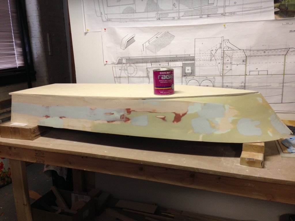
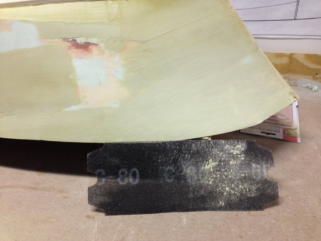
Slowly but surely we are getting there. Today I applied the Rage filler shown in the accompanying picture after machine fairing the Golden Edge (greenish) compound previously applied. The Rage product (light blue compound) is also a filler but it has properties that make it much easier to use. It is a less viscous compound and it has a slightly longer open time for working. When it comes time to sand it is much easier to sand and that alone makes it preferable. Here is the port side almost ready for final sanding. It will then be primed and glazed and if need be primed again.
-
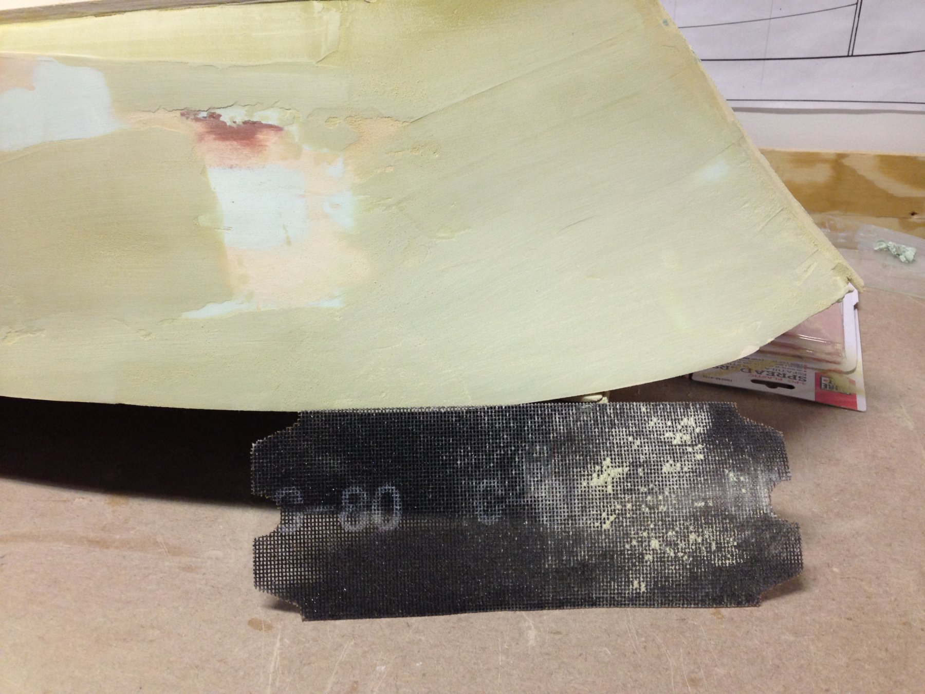
Back to getting the hull ready for painting. I was at the museum today and experimented with the 3M Golden Edge FILLER. Therein is the operative word. It is no easier to apply than the 3M Platinum Plus Glaze. There is the other key word. It's open time is about 3 to 4 minutes as described in the worksheet. It dries rock hard and can be applied up to 1/4 inch thick. It is tough to hand sand but does give a decent substrate finish for a surface glazing. I had to resort to drywall sanding sheets of 80 grit to bring down the surface as it clogs regular sand paper quickly. As a surface re-enforcement it is quite good for a display model it is overkill in my estimation. We will revert back to the 3M Platinum Plus Glaze prior to finish painting.
-
Tom: That is very good news indeed. We were quite puzzled when we tried to get the drawings the first time around that it was so difficult. Even when one of our group who is retired ex-Navy in the ship building end of things tried. I am going to relay to him your findings/observations. he is away in sunny Florida right now so it may take a bit of back and forth exchanges. You are kind to offer help. Also the Navy gave us the drawings there was no charge. Joe
-
Recommendations For A Good Milling Machine
Thistle17 replied to Thistle17's topic in Modeling tools and Workshop Equipment
Just checking back in to give some more feedback on my 5400 DRO milling machine from Sherline. It is all good news and made so by the use of the DRO feature of this machine. I am not a trained machinist but can get by and have for quite a number of years. Now that I have the digital readout capability my work products have improved. This is so evident when parts replication is required. I do find that my blank mounting is somewhat of a challenge and I need to work on that. I think it can be improved with the Sherline's line of tooling plates. I plan to order one shortly. Right now they are on sale. Joe -
Thanks GrandpaPhil I knew someone had an answer out there. I did try once more at the Kindig It web site and this time they have an auto response of who to reach for subject specifics. That wasn't an access for me before. I am off and running to see if that will fit the bill! Thank you very much. And here is the PDF for usage. One can use it on wood and it has a reasonable open time before it starts to setup. http://multimedia.3m.com/mws/media/649535O/3m-golden-extra-filler-01127-01177-01277-01317.pdf Joe
-
Mark I have contacted them twice through there web site Kindig It Design but have yet to hear from them. In looking more completely on line my use of the term "conformal coating" may have been inappropriate. That comes from my days working with electronic circuit boards which were coated to reduce the effects of environmental conditions. That product material was never meant to be sanded once applied and if the board was repaired it had to be patch coated again. If I do not hear from them in the next 2 weeks we will revert to the hobby mesh fiber cloth and we will glass it. I just hate working with it because of VOCs. Joe
-
Many thanks Mark I will give thatprogram credits a try. Joe