Thistle17
-
Posts
1,054 -
Joined
-
Last visited
Content Type
Profiles
Forums
Gallery
Events
Everything posted by Thistle17
-
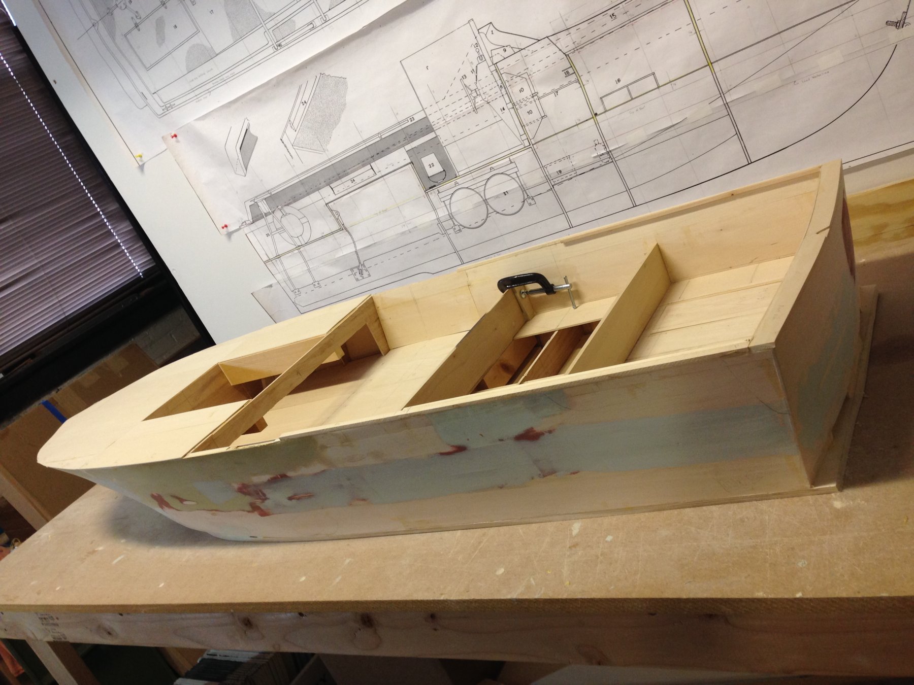
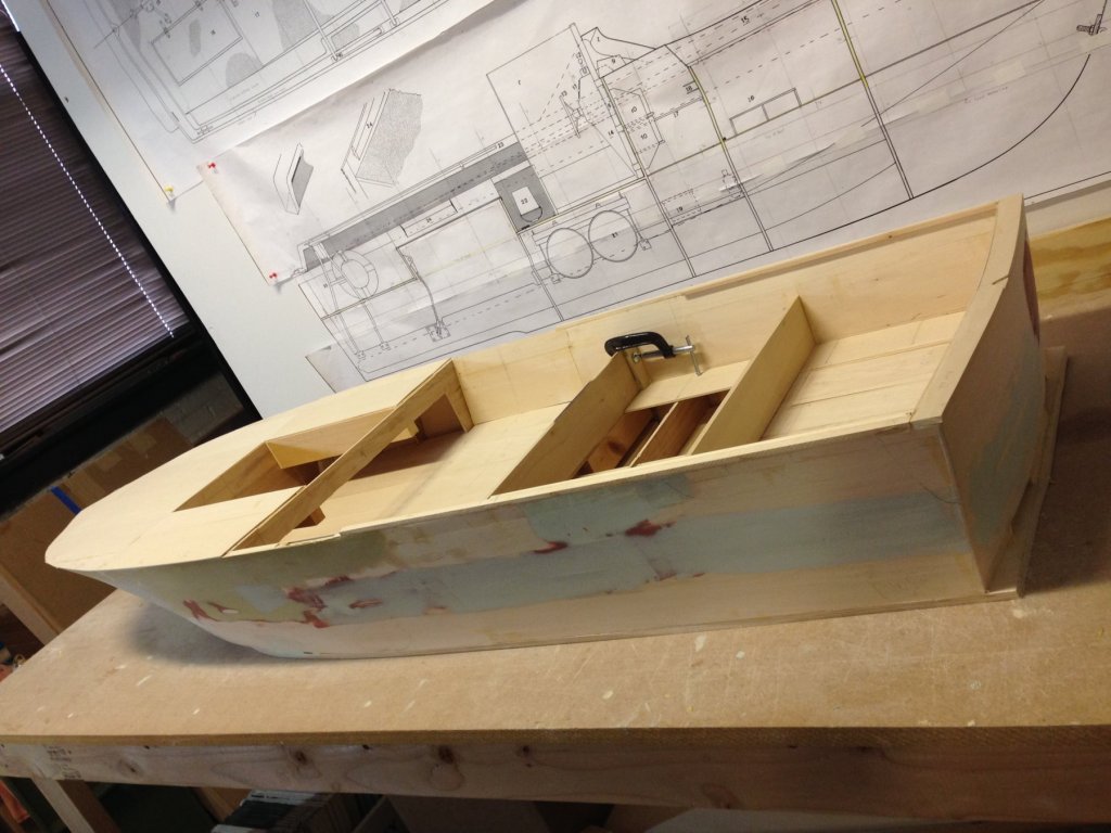
 Yes, we have been off the radar since April. Too many projects, not many hands on deck and oh so little time have contributed to a slow down in the build. However I will lament no further as 4 of our group has been diligently but sparingly been at it since April. So in the attached photo is somewhat of a milestone for us. We have completed inner skins and applied a false deck forward of the control station. We have added the bulkwarks that will form the platform aft of the control station that conceals the engine fuel area. We have also added the aft rail and some of the side rail. In process are the engine air intakes (the dark area in the plan above) with one trial fitted today. The open area forward is the beginning of the twin gun turret which will be added in much more detail in the coming weeks. As soon as the air intakes are completed the contoured deck will be fashioned all the way to the bow. It is quite oddly shaped and we have had to constantly refer to the photos supplied by our friends at Patriots Point. As soon as we are satisfied with the deck construction the unit will be prepped for spray painting of the hull with primer. We have to get to that point soon as we are not permitted to use spray equipment even in this storage area.
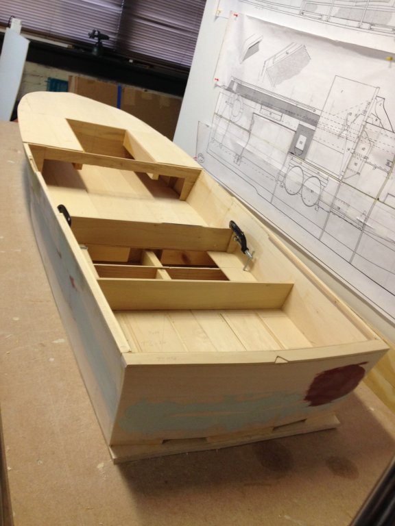
-
It has many uses. A number of my woodworker colleagues use it to do inlay work for federal furniture and the like. One can even do arcs etc. with the proper home made jigs. Joe
-
Got it! Indeed Leopard I should have done what you did. I guess what was throwing me off was what appears to be milling marks on the face of the large billet. Joe
- 1,784 replies
-
- 3
-

-
- winchelsea
- Syren Ship Model Company
- (and 1 more)
-
Forgive me Chuck, I have read and re-read your milling description and I am still wanting. In the first picture with the billet, is the grain running from L to R? If so then when you rip off a 1/4" sub-billet, say from that upper edge of the billet your "sub" billet has a clear face and the resulting planks are almost 1/4 sawn? Am I correct? And you can get the same results with cherry? And in terms of bending is edge bending any more difficult? Thanks. Joe
- 1,784 replies
-
- 1
-
-
- winchelsea
- Syren Ship Model Company
- (and 1 more)
-
Self made clamps and jaws.
Thistle17 replied to ymperivm's topic in Modeling tools and Workshop Equipment
Thanks Bob I had forgotten this method of the scarf joint. On Cheerful there is even a plank in the bow that does not fall on a bulkhead so this would have been ideal. I certainly could simulate the butt joint even with the scarf. A bit extra work but given the results worth the effort. Joe -
Self made clamps and jaws.
Thistle17 replied to ymperivm's topic in Modeling tools and Workshop Equipment
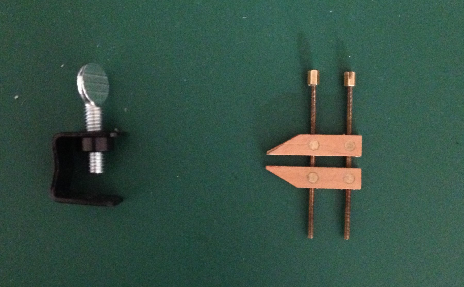
I still have so much to learn and become proficient at in terms of hull planking. In planking Cheerful I have been frustrated by certain planks not "laying down" to my satisfaction and then having to rationalize that I will sand down the offending neighbor to achieve a more acceptable plank to plank surface conformity. This has been especially so when laying down a short plank that ends on an intermediate bulkhead next to it's neighbor that has spanned several bulkheads. There is a natural bend or contour to the latter. While the short plank tends to be more or less flat across its terminating bulkheads. One is left to sand the area until surface conformity is achieved. Even pre-bending the short plank may not achieve desired results. I have used the miniature Jorgensen clamp shown in the early stages to clamp adjacent planks and internally add a small piece of glued veneer (with grain direction as in the plank direction) to smooth out the area. It works quite well. Now when one approaches the keel most clamps cannot be placed because of interference with the keel for example. In looking around I found the second clamp (in a set of 5) for less than $13 on Amazon. They are miniature welder's clamps for temporarily holding rocker panels etc. in place for alignment to doors and columns. The advantage of this type of clamp is that there is little to no interference in tight spots as mentioned. So piggy backing on "ymperivm's" lovely adaptation of miniature clamps here is yet another option. These are about 1/2" wide with a throat just about the same dimension. One could easily make these at home out of 1/8" thick aluminum channel of any width and achieve the same capability. Just thought I would share this. Joe
-
Jim I am sorry I haven't been on this model for some time other than to repair alignment of a bulkhead that went astray while installing them in poor light at the Strong Museum. I had thought of adding the extra detail between decks and then discounted it. Primarily as I am driving hard on Cheerful to finish hull planking and get on with more of the fun stuff associated with the model. I am not an accomplished plank installer but am slowly getting the hang of it so there is hope for me. I attended the 37th annual model conference in New London and picked up Syren's next kit, The Medway, and anxious to start that but holding myself in check. So things are starting to pile up. Essex still intrigues me and I think when Cheerful planking is done I will pick her back up and proceed on her hull albeit at a halting pace. I may have said this already I am going to do her above the plating line in Alaskan Yellow Cedar and below that I will probably use Bass. Just for economy sake. In regard to fillers I did Cheerful with Balsa fillers and ended up taking them out as planking below the wales proceeded as they just got in the way. It was useful in the fairing stage but became a nuisance thereafter. I was pleased with the blocking I installed on Essex, instead, as it made for quite stiff bulkheads. Joe
-
USS Agawam by Thistle17 - Scale 1:48
Thistle17 replied to Thistle17's topic in - Build logs for subjects built 1851 - 1900
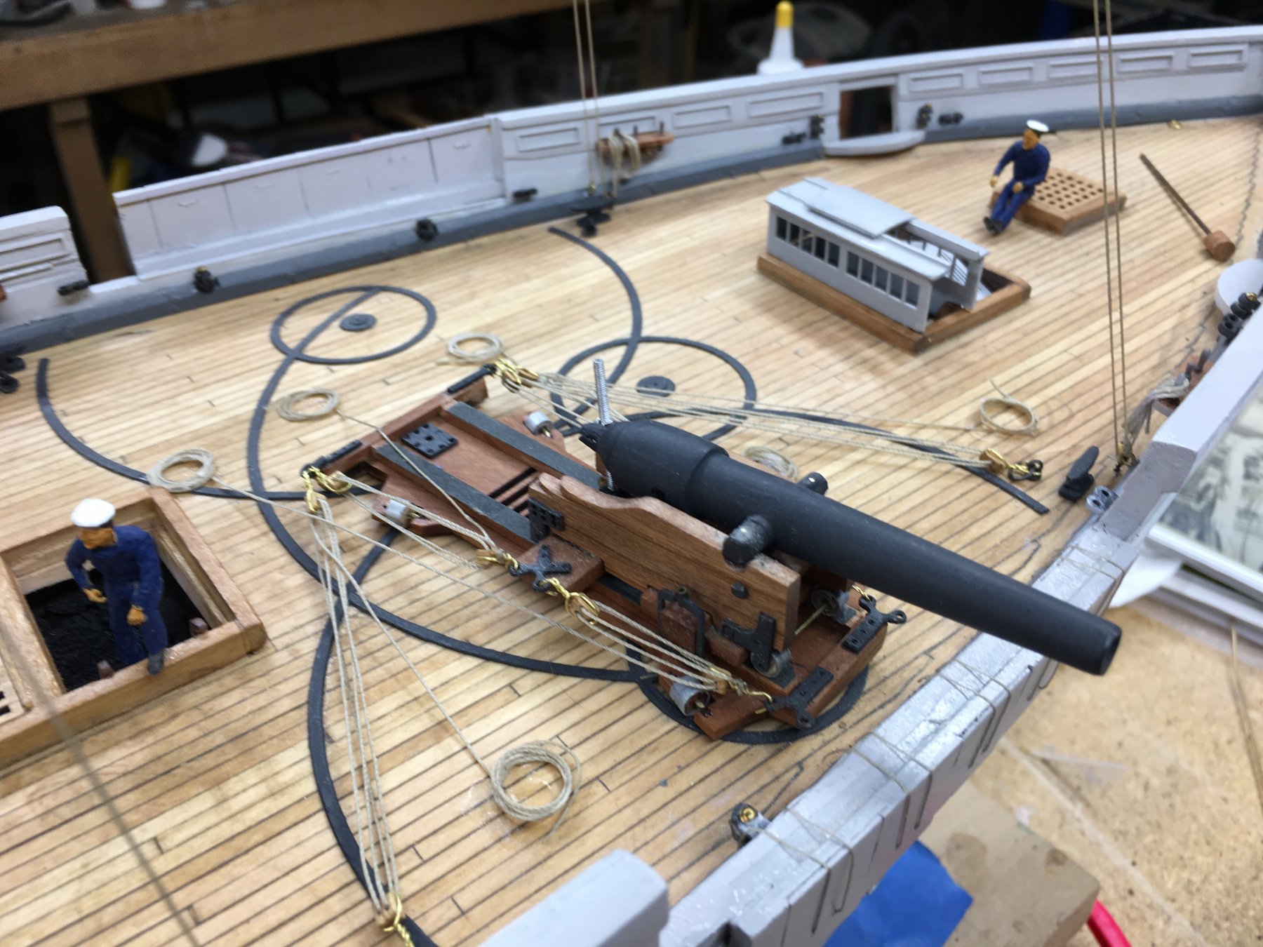
In the final stages of construction Bill had cannon and associated deck ware to consider as well as the lifeboats. The cannon were 100 lb, 24 pound and 12 pound. With all cannon Bill cast his own utilizing traditional methods as shown in below. Now the carriage for the 2 100 pounders is a bit unusual as wel as its aiming and tracking mechanism. I believe a 100 pounder must have weighed in at 10,00 pounds or more so the carriage had to be quite stout not only for the gun weight but for the charge. The attached pictures reveal Bill's progression in armament development. Here again Bill used computer aided design to develop the deck "track" for those guns. Note the removal of a section of the bulkwarks to enable cannon aiming.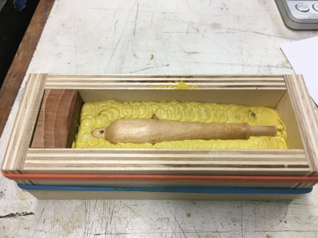

-
USS Agawam by Thistle17 - Scale 1:48
Thistle17 replied to Thistle17's topic in - Build logs for subjects built 1851 - 1900
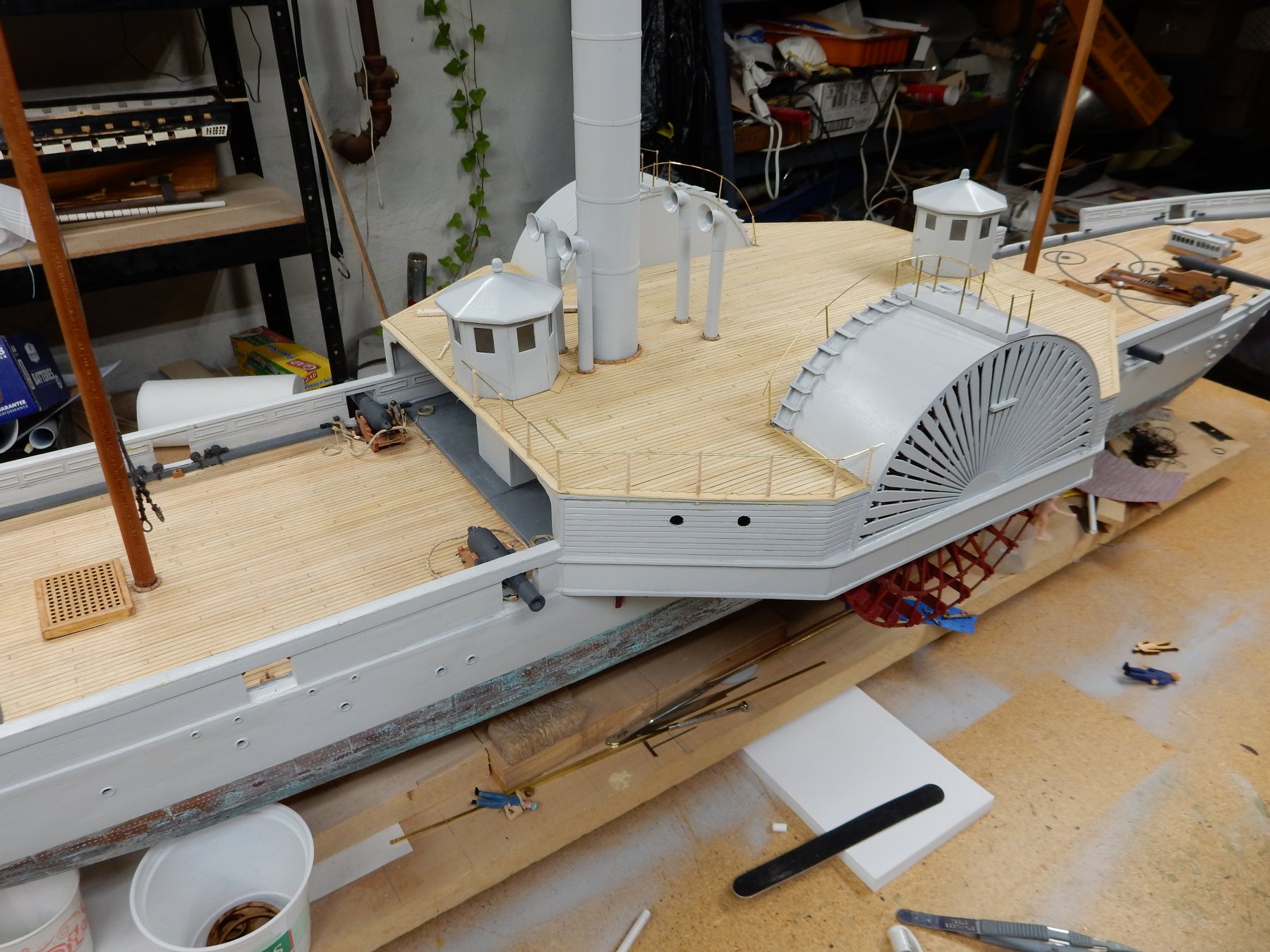
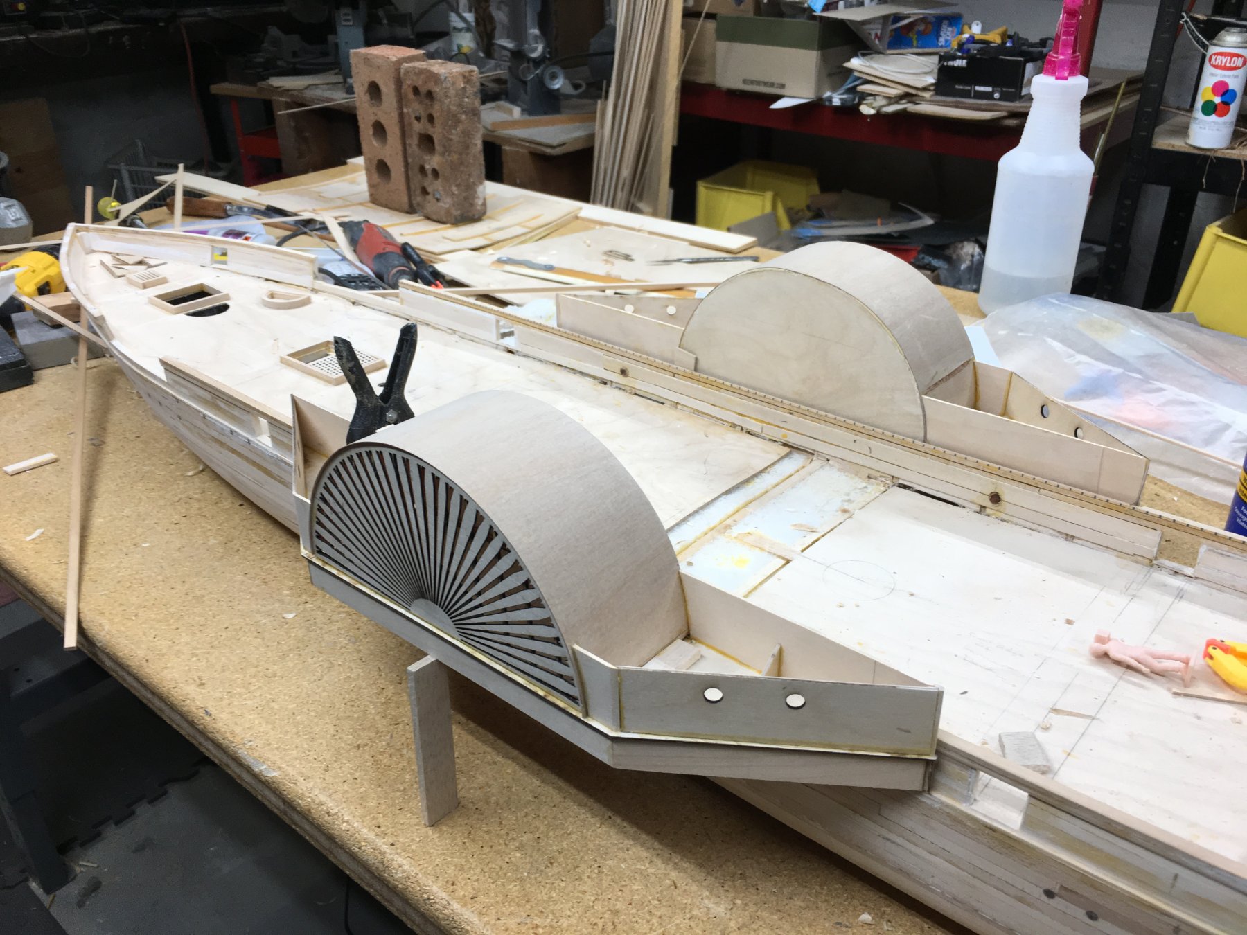
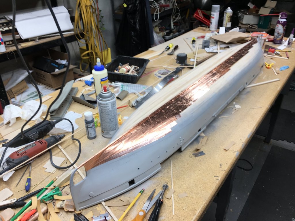
I will pass on your comment Johann. Bill will be pleased. As stated the deck furnishings were not elaborate so deck houses, mast towers, paddle wheel ladders etc were fairly straight forward. The twin deck houses were made from card patterns and replicated in basswood. Here deck planking is in place and some masting and rigging were started. I haven't asked Bill about the air vents but I will. I wonder if they were reversible for change of direction. One thing I forgot to mention is the rudders. They are replicated at each end of the vessel. When steaming forward the "front" rudder was locked in place. Note the patina on the copper foil used for the simulated plating. It is quite convincing compared to the virgin material. It adds so much to the overall appearance of the model. It does appear that there have been some accidents in dry dock in this picture as several workers or seaman have fallen off the build.
-
USS Agawam by Thistle17 - Scale 1:48
Thistle17 replied to Thistle17's topic in - Build logs for subjects built 1851 - 1900
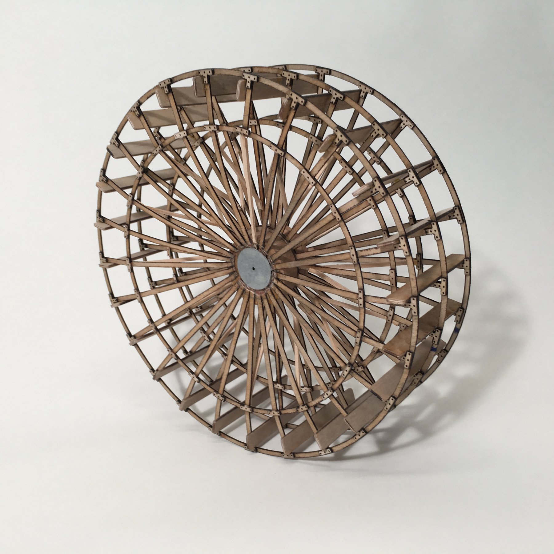
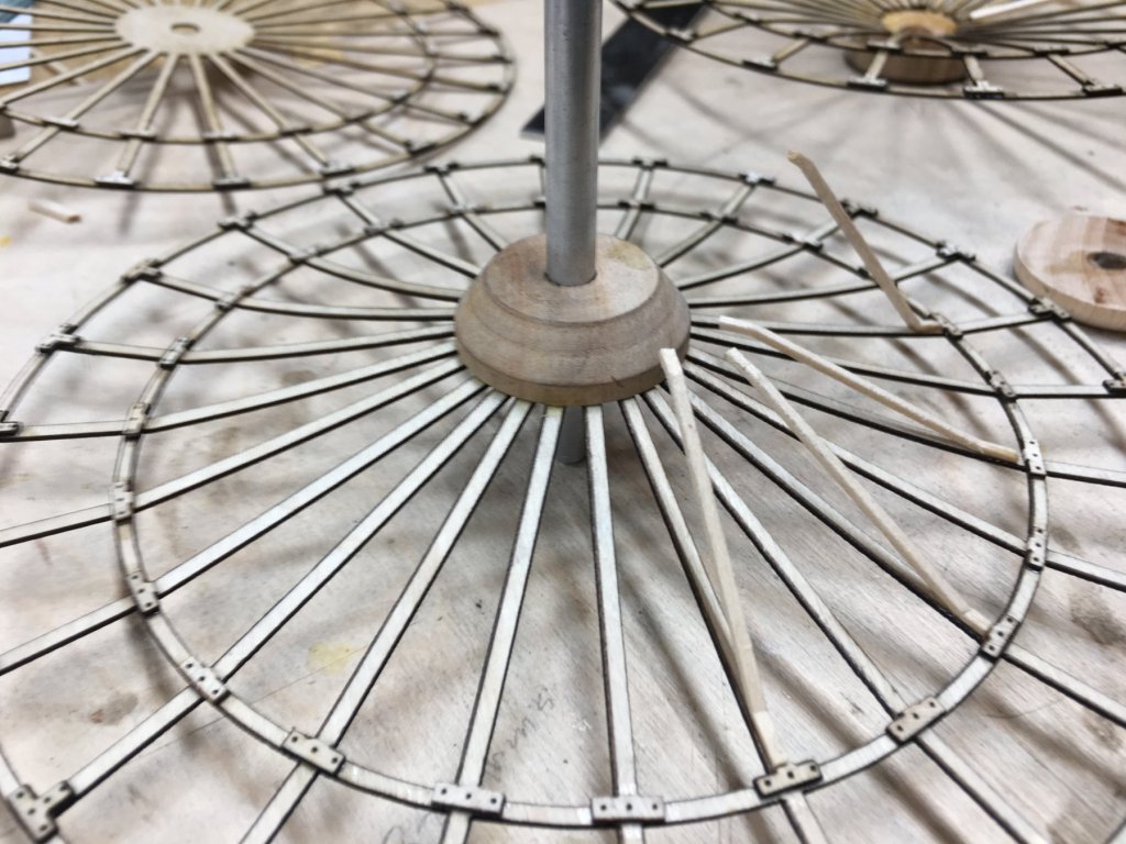
The most challenge Bill had was in the development of the paddle wheels themselves. Each unit is made up of three spoked discs separated at the center by a split hub. The hub area of the outer "discs" were not tied down but were left free to be bent inward and secured to the hub. Try making this free hand with these results. Note as well, the laser created re-enforcing plates for the radial elements. Technology and good ole Yankee Ingenuity at work here!
-
USS Agawam by Thistle17 - Scale 1:48
Thistle17 replied to Thistle17's topic in - Build logs for subjects built 1851 - 1900
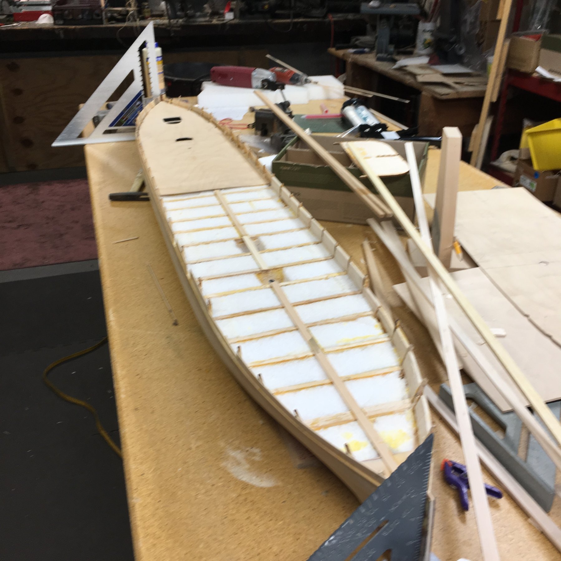
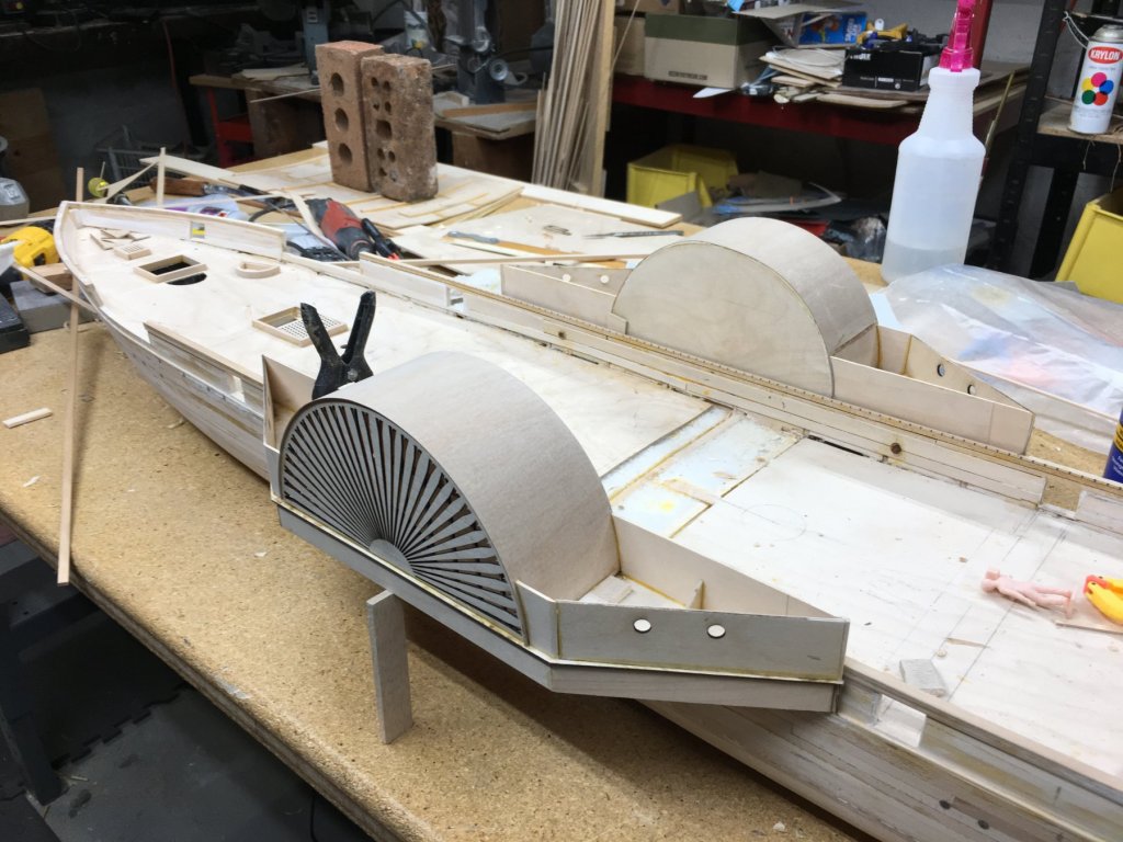
Hull planking was dispatched fairly quickly as the lines of the hull make for easy work amid ship and with symmetrical bow/stern. Open cell foam was added between bulk heads for increased rigidity after which false decking was added. In the second photo one can see that the deck detail is not overly complicated but are a bit massive so attention to detail here was paramount. The outside paddle wheel grill, if you wiil, was designed via Corel Draw and laser cut. In a case like this, that technology is a blessing!
-
USS Agawam by Thistle17 - Scale 1:48
Thistle17 replied to Thistle17's topic in - Build logs for subjects built 1851 - 1900
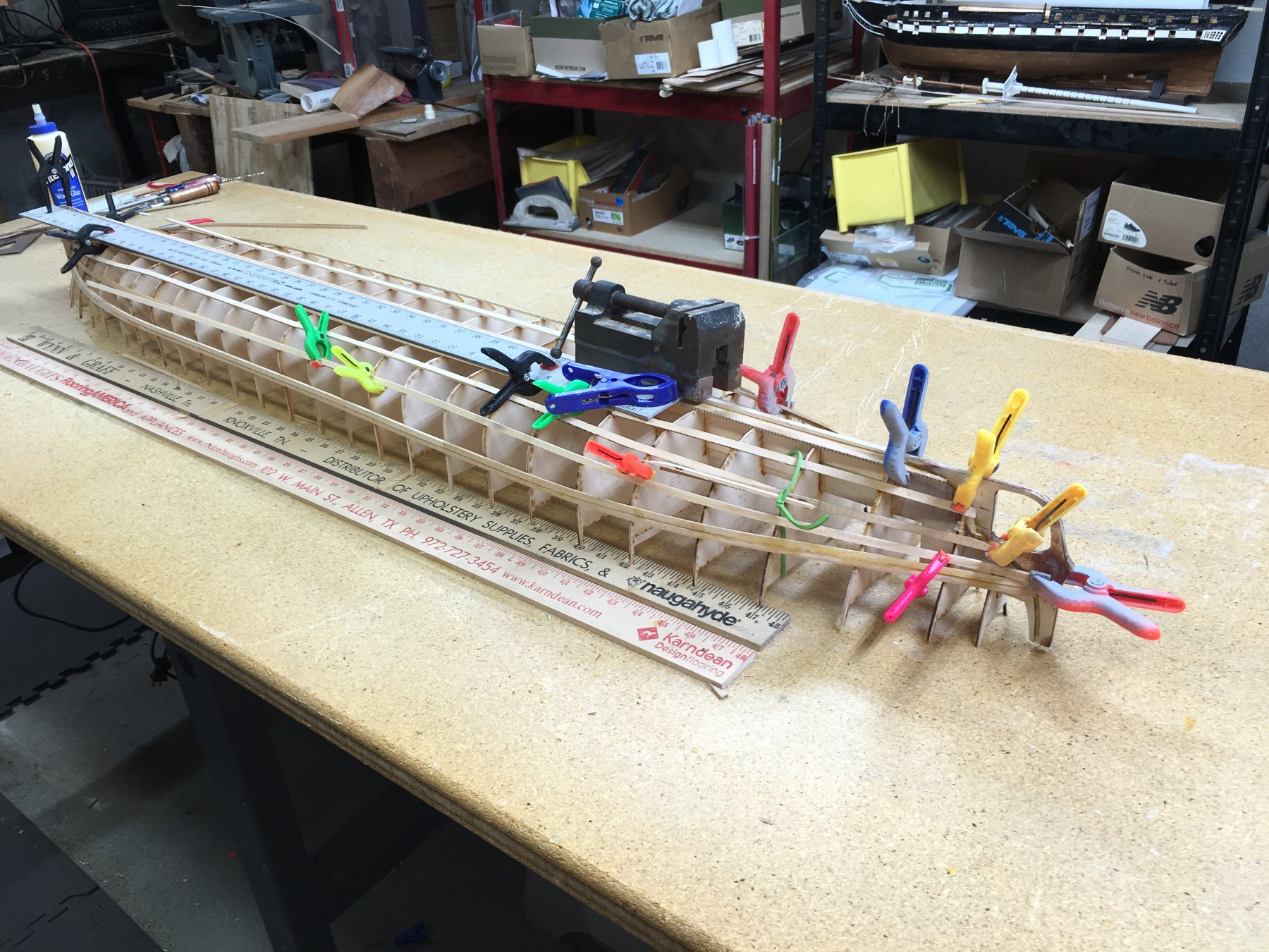
We all have our methods and materials we favor in model building. In the attached photo you see that Bill has begun planking the complete hull for Agawam. Do you notice the yard sticks in the foreground of the photo? Do you think they are for measurement? Well think again. They are his planking in the raw! Sometime back Bill came upon a supply of yard sticks from some manufacturer. He bought an abundant supply of them (at the right price) which he has milled to fit his needs. They are of basswood (or similar material), are quite straight and void of imperfection so they make fine 3 foot length stock for planking. Bill is always looking for solutions from all sectors.
-
USS Agawam by Thistle17 - Scale 1:48
Thistle17 replied to Thistle17's topic in - Build logs for subjects built 1851 - 1900
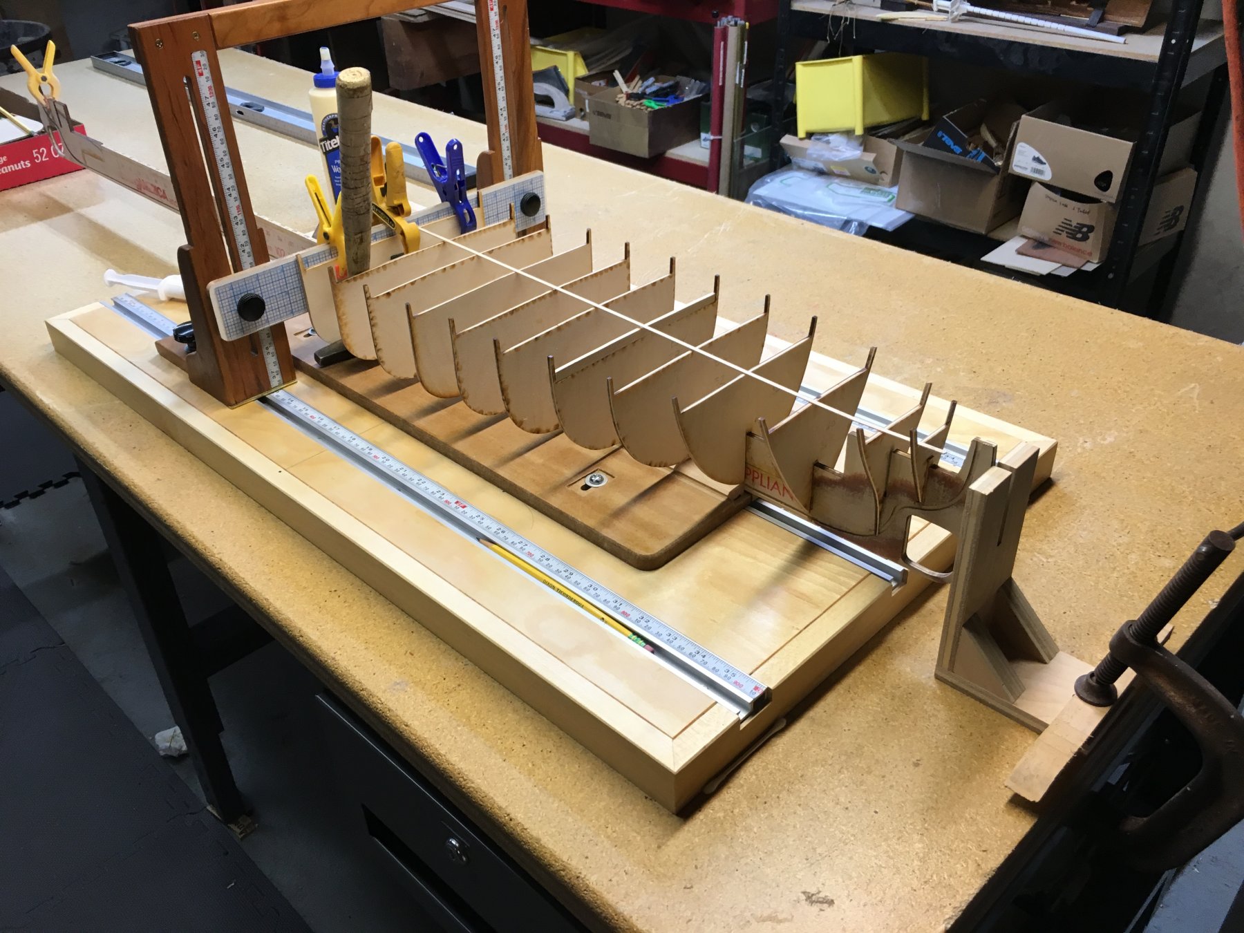
As stated earlier Bill has built numerous models over the years. He has built matchstick versions early on, solid laminated hulls and plank on bulkhead. In this case he chose to build a POB hull. Bill will scan station profiles into Corel Draw and will "piecewise" smooth the lines to achieve the desired bulkheads needed. His output is fed to a laser cutter at a local vendor he has used before. There is always some "put and take" but ultimately he achieves the desired outcome. Now this model is over 5 feet long and the bulkhead alignment jig is only 3 feet long so the hull had to be made in two halves. The hull is symmetrical about the mid ship station so it was a repeat of the initial process. Obviously keel alignment had to be carefully observed. You can see the keel extension beyond the rear of the jig. Here is one half of the hull on his large work table.
-
USS Agawam by Thistle17 - Scale 1:48
Thistle17 replied to Thistle17's topic in - Build logs for subjects built 1851 - 1900
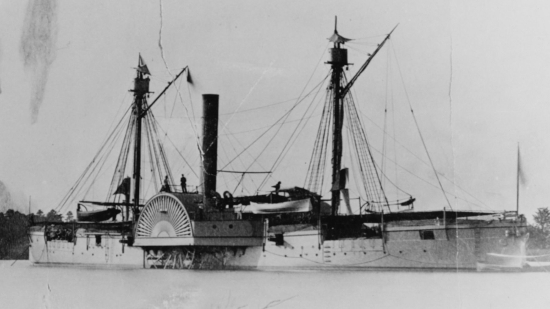
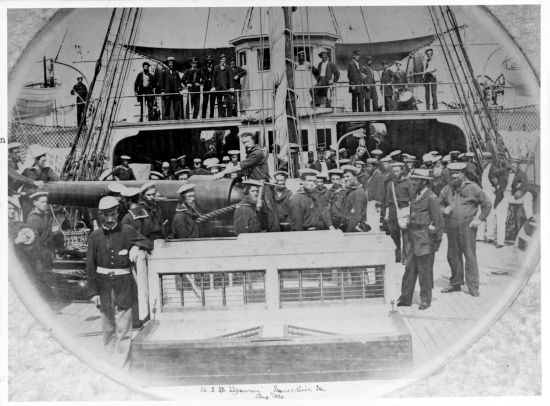
There is a decent top level bio on Wikipedia regarding the USS Agawam. She was built in 1863 in Portland Maine and was among 28 built over a period of just 2 years (1862 -1864). with a crew of 145 to man her steam and supplementary sail propulsion she was able to navigate the inshore seas and inland waterways. Her armament consisted of 2 -100 pounders, 4 - 9 inch, 2- 24 pounders (smooth bore), 2- 12 pounders. More can be found on https://en.wikipedia.org/wiki/USS_Agawam_(1863). Photos were invaluable to Bill in determining deck detail. Later on you will see that Bill's model does not display the tarpaulin covers seen in this photo. But his model adds the framework for accuracy. Joe

-
Bill E. is a founding member of Model Shipwrights of Western NY and has been modeling since a very early age so his builds are many and his techniques over the years have evolved and embraced modern technology to a large extent. I would have to say he is our main technologist and through him we have been introduced to these modern techniques in a first hand manner. Bill's interest have almost exclusively been in the area of early America powered Navy and Civil War Era craft. He comes by the Civil War interest honestly, as his great grandfather was a captain in the RI First Calvary. Bill even wrote a book about him," Don't Tell Father I have Been Shot At" as he was a war hero and had kept many artifacts and writings about his service. There is a brief on the Amazon Book Store for those interested. Many of his models have been donated or loaned to various museums around the country and you may see one of his latest works , the USS Langley at the Smithsonian. His most recent endeavor has been the USS Agawam, a double ender gunboat of the Sassacus class built during the Civil War. A reference can be found at https://en.wikipedia.org/wiki/USS_Sassacus_(1862). This vessel is on loan to the Military History Society of Rochester NY and is the center piece of a recent expansion of the museum. What promotes Bill to the front of our group is his penchant for research, incorporation of modern technology, his vision of model end point and undying passion. Bill has been known to trot down to the National Archives, camp out nearby and bike in to research a subject. He employs computer design to fabricate laser cut intricate parts, he employs vacuum forming techniques for certain elements and he utilizes numerous finishing techniques that set his model apart. Herein is not exactly a build log but a build progression hopefully showing his methodology in building Agawam. Please follow along as entries are made over a short period of time. Bill is a modest guy so if there are questions of further inquires I will get answers as this thread unfolds. Joe
-
Table saw with a reasonable price
Thistle17 replied to Clark's topic in Modeling tools and Workshop Equipment
I could come down on both sides of this thread. All prior comments can't be denied. Having said that in the past I have leaned to the side of buy the best you can afford and adapt using your skills and knowledge to overcome tool shortfalls. For example in my woodworking shop I do not have a top of the line table saw. It is a Delta 10 inch, contractor's saw with a full cast iron table that I later added on side and outfeed extension tables with a Unisaw fence. It has been a workhorse for nearly 45 years. It never disappoints and replacing it is not a near term thought. The only thing I was uncompromising about was the blades. They make the work a joy. They just have to be kept sharp and treated with respect. A number of shop made jigs have made this saw even more versatile. I sometimes chuckle to think that when I bought the Byrnes saw I paid as much for it as I did my shop saw. I have never looked back with regret. In modeling we work with thousands of an inch in some cases. That is hard to achieve with some model saws on a repeatable basis. Mitre slots are sloppy, blade arbors are not adjustable to achieve feed parallelism or their run out is poor. I could go on. So to me there was no question as what to buy and how much to spend. And if I need a bit of self delusion I always ask myself..."Spread over a life time how much is this purchase really costing me?". Joe -
Clever use of the ubiquitous Lego Blocks. I started mine on vacation without the helpers and it caused me some problems along the way. Ensuring the "trueness" of the bulkheads is key to this little model. You are on the right track. Joe
- 33 replies
-
- 2
-
-
- 18th century longboat
- model shipways
- (and 1 more)
-
There are no words one has to recognize what you and others do in the line of duty. Having had a family member who was in the city fire department I am aware of what you and he have done! Thank you. Mending is the most important thing you can do. The body is an amazing machine. I am a returning modeler as well. When you get started the advice I have learned from others is to proceed slowly, accept that you will make mistakes and don't be afraid to do over. If you live in an area that has ship modelers do join when you can. If not put a post on the this site in the section that lists club activities etc. Also The Nautical Research Guild kindly supplied me with members in and around my area. We started with about 7 people and now we are about double that. Joe
-
We are still here but not as active as we wish. As I am sure you all know life can get in the way. In any event we have an important update regarding reference modeling material. A good Samaritan on the west coast was able to get all the PBR drawings declassified through contacts that provided an avenue into the archives. The drawings we obtained were of good use but did not have what I would describe as next level detail. For example the drawings and dimensions of the forward tub for the 50 caliber guns. Well we have them now and we will have to give credit to our colleague Joel on the west coast. Our lead "general contractor" is now converting those drawings to 1:6 scale for our use. This windfall is going to save us so much time. We are truly grateful! So Tom we are all set and thank you for your efforts. Since February little has been done on the model but will start up again as soon as this week. We have to finish the starboard side fairing but after that it we will begin the inboard floor and skins. We do have some additional pressure afoot. The Military History Society Museum, which hosts us, is expanding. In the new addition there is a display area for this model that awaits us. It will be in somewhat of a diorama presentation, at dockside, in the process of being loaded up for a mission. No pressure eh? Joe
-
Hobby saw with larger table top
Thistle17 replied to ONEVW's topic in Modeling tools and Workshop Equipment
Jim without giving away any trade secrets what is involved in modifying the standard table top? I presume it is just the table top. Can one just send in the top? I think this product is an excellent accessory! Joe -
Hobby saw with larger table top
Thistle17 replied to ONEVW's topic in Modeling tools and Workshop Equipment
Jim I am interested in one can you post a picture? Joe -
You should be aware that Thurston has closed if you do not source your blades from Byrnes. Here is another source that Thurston recommends: MALCO SAW COMPANY 22 FIELD STREET CRANSTON, RI 02920 PHONE: 401-942-7380 FAX: 401-946-6092 CONTACT: GREG LIVESEY Email: greg@malcosaw.com Website: www.malcosaw.com
-
My wife reminds me "You are getting older", not "your getting old". This is such a great way to satisfy your creative needs and produce something of worth! Welcome. Joe
-
Adapting DRO Devices To Shop Tools
Thistle17 replied to Thistle17's topic in Modeling tools and Workshop Equipment
I have just heard back from the Any Time Tools people. The 12 inch unit on their web site is no longer available. They have directed me to the Amazon offering which has an advertised accuracy of .002 over 6 inches and .004 over 12 inches. I conclude from this that the referenced part performs as my older unit and is adequate for most operations one would need for ship modeling. To this point, with some outliers, my outdated unit is performing essentially as the newer ones. The display functions seem adequate for normal saw operations. They communicate to me there is the capability to add a DC power source although the site depicts battery power. Mounting can be achieved through a separate attachment. Here are the references they have provided. https://www.amazon.com/dp/B01G4FQJI6?ref=myi_title_dp https://www.amazon.com/dp/B01CPLEW46?ref=myi_title_dp https://www.amazon.com/dp/B00INL0BA2?ref=myi_title_dp Joe -
Adapting DRO Devices To Shop Tools
Thistle17 replied to Thistle17's topic in Modeling tools and Workshop Equipment
I happened to stumble upon, a new to me technology for DRO application. It is termed magnetic technology and in comparison is quite impressive in terms of performance with accuracy and repeatability beyond the performance of the capacitive type configurations. Here is a site for reference http://www.dropros.com/DRO_PROS_Digital_Readout_Magnetic_Scale.htm That's the good news. The bad news is the cost for a 12 inch unit in the range of $400 to $500! I still await a response from the Any Time Tools, so in the mean time I did rerun the test using the saw blade as a reference and again using the method suggested by Bruce in his post. For his suggestion I clamped the miter gauge to the table top and used its in board edge (the mitre bar) as a stationary reference. The other aspect of this test was that I ensured the 'Z' bracket "play" was canceled out since I now believe one must fasten it to the fence traveler as opposed to rare earth magnet attachment. The results do show some deflection dissonance caused by the blade method but the results are relatively the same with no outliers. I conclude, even with my older unit, that the accuracy and repeatability are worth the effort of adapting the unit to the saw. Joe IGAGING.Test.xlsx