HOLIDAY DONATION DRIVE - SUPPORT MSW - DO YOUR PART TO KEEP THIS GREAT FORUM GOING! (Only 13 donations so far - C'mon guys!)
×


Thistle17
-
Posts
1,053 -
Joined
-
Last visited
Content Type
Profiles
Forums
Gallery
Events
Everything posted by Thistle17
-
 Inspirational Bob! I just managed to get all my bulkheads completed yesterday and I have yet to build my build platform! So it seems "I have miles to go before I sleep". I will be tuning in to you for inspiration and guidance. Don't lose me in the dust! Joe
 -
Thank you both for your input. It appears I have over thought the method. I know I have said this before but I have to say it again. The information sharing of this forum is amazing! Joe
- 1,784 replies
-
- 2
-

-
- winchelsea
- Syren Ship Model Company
- (and 1 more)
-
OK Chuck I have a question. In planking the bow of Cheerful I found that some of the planks fit into the rabbet were less than perfect. Most ended up sprung against the stem member but a few had drifted away from that tight condition. Here is how I was planking the bow: 1. slight bevel on the fore end of the plank on the underside of the plank 2. plank end tapered to the stem angle 2. heat bent around a canister cap with a radius slightly tighter than the bow radius. 3. theoretically the tighter radius when glued in forced the plank up tight against the stem Should I have skipped step one? Joe
- 1,784 replies
-
- 2
-
-
- winchelsea
- Syren Ship Model Company
- (and 1 more)
-
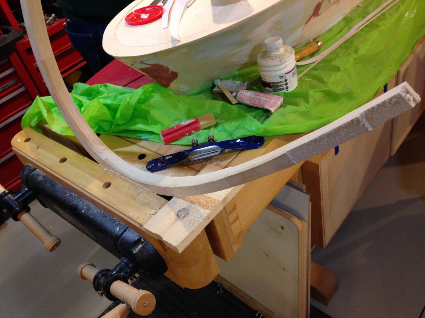
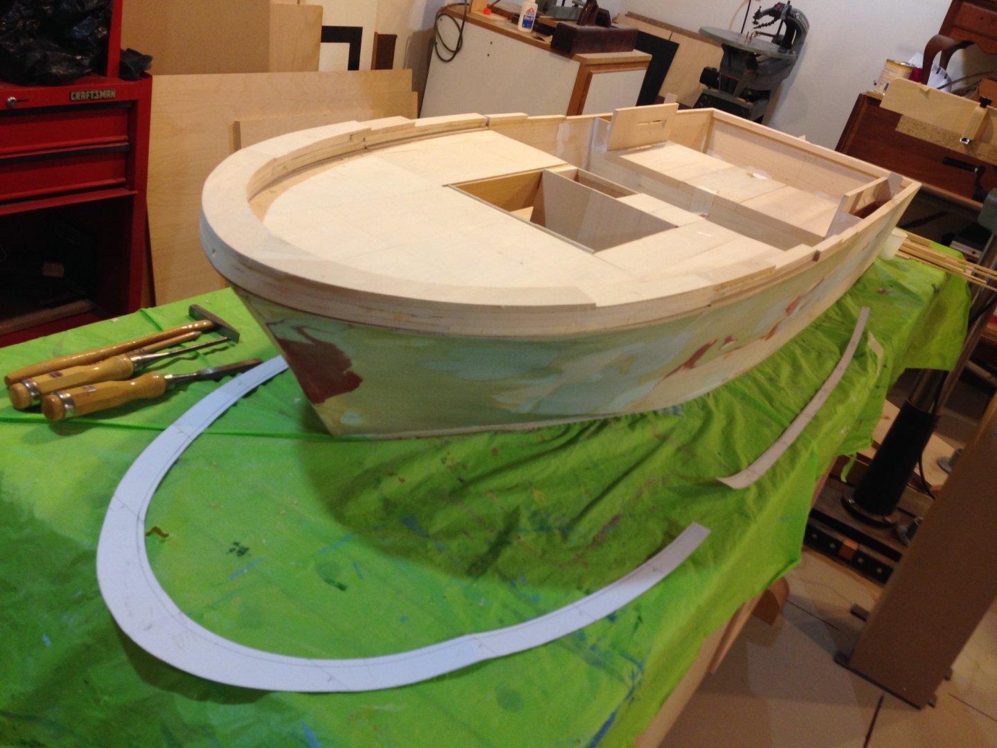
Weather in upstate New York has been superb for the opening of the fall season so it has been hard to get back to the shop and work on the PBR. We forced the situation today though. Most of the work has been focused on shaping the "rail" that surrounds the bow to about 2/3 of the vessel. As stated earlier it starts out at 1" at the bow tapering to 0" at the mid point of the engine covers. I resorted to using my hand power planer to achieve the appropriate taper of the rail after marking off the taper using battens. I then smoothed the outside face roughly on my oscillating sander table and then used hand sanding to gain a satisfying contour. The inside was another matter. It has a taper from top side to its bottom. The complication is the taper is not uniform. Topside thickness was outlined using a template. Bottom side was also defined by its sister template. Using a spoke shave the inside taper was roughed out, moved to the oscillating sander and finally hand sanded close to finish dimension. Some Easy Sand was applied to void areas but for the most part it is ready for finish sanding, final fitting and install. As it turns out this depiction doesn't really show the taper well. Hopefully one gets the idea though. Joe
-
Good idea Rusty on weighting them down. My environment is a bit more humid and I have even got in the habit of covering the work in progress with plastic sheeting. Those scroll saw blades do a great job by the way! Question: I believe you said you were using Birch ply is that correct. Is it Baltic Birch? Joe
- 642 replies
-
- 2
-
-
- winchelsea
- Syren Ship Model Company
- (and 1 more)
-
My progress reminds me of the sprinter who is the last off the blocks when the gun goes off. I finally received my 1/4 ply from National Balsa. It got lost in the delivery cycle but ultimately showed up at my door. I ordered 10 sheets and oddly they sent 12. It is all shrink wrapped so a quality inspection will soon be made. I guess they know I am prone to mistakes. Fabrication of the bulkheads should begin very soon. My race metaphor is how I feel right now but I do understand this is not a race to the finish! Joe
-
Your model build is a joy to follow. I cut my teeth on the Bluenose from AJ Fisher sometime ago. Shaping the hull with carving tools etc was wonderfully satisfying. I have been drawn into the world of plank on bulkhead and while some find it very much to their liking I can't say I do. I find myself wanting to get onto the detail of the model but plodding along on the planking. Redjacket is a beauty and your progress reminds of the merits of solid hulls. Sitting on my shelf is The Flying Cloud from your namesake just waiting for my attention. You inspire me. Joe PS The vintage of the Flying Cloud if I am correct has the lead alloy fittings. Any suggestions?
- 356 replies
-
- 1
-
-
- red jacket
- finished
- (and 1 more)
-
Mike you set a high water mark in terms of execution! Always a treat to witness your progress. Above you reference a dowel use in the counter. Are you using it to contour the plank along its length in this are? Can you explain it a bit more please? Joe
- 607 replies
-
- 2
-
-
- winchelsea
- Syren Ship Model Company
- (and 1 more)
-
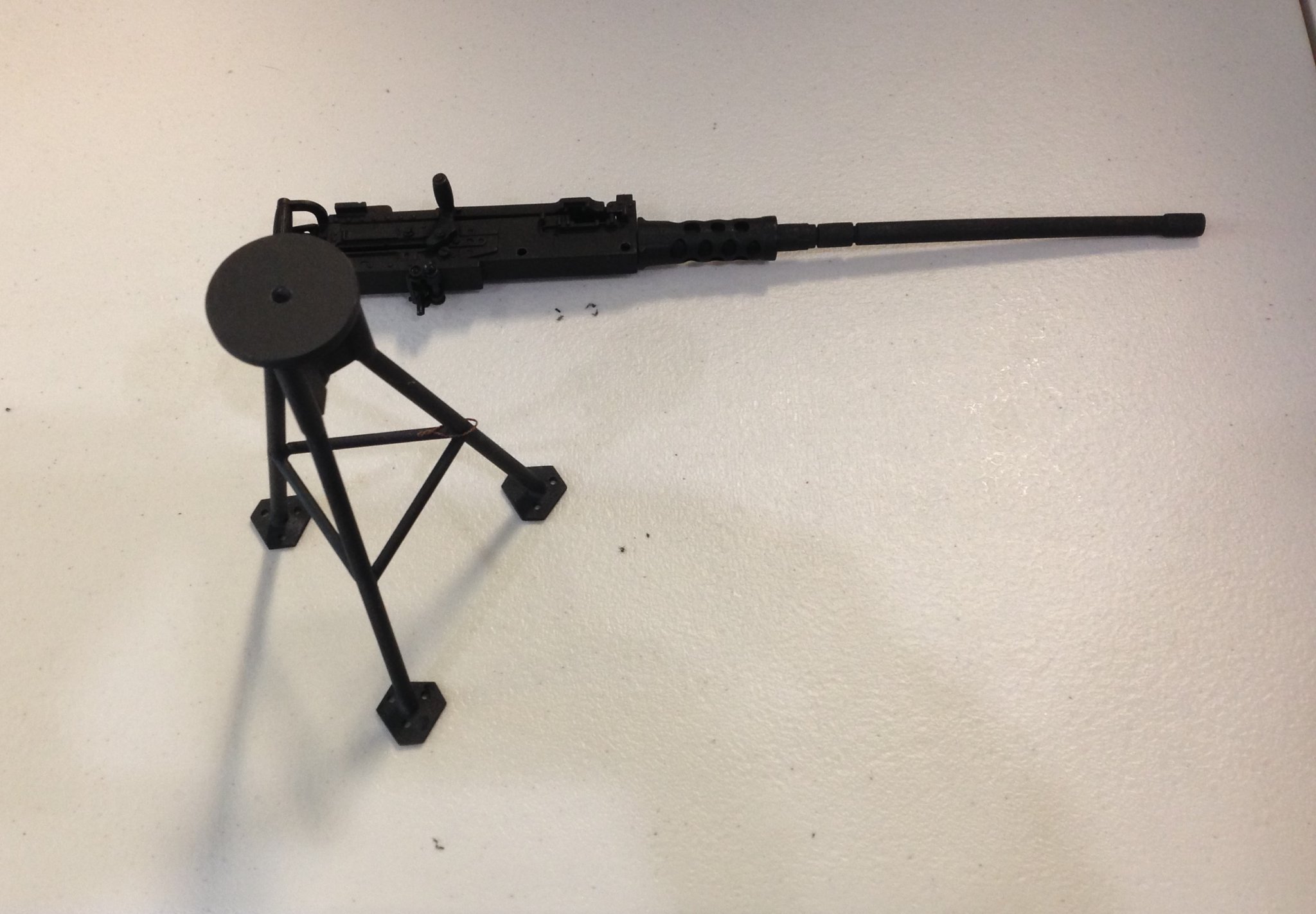
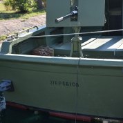
Well here it is September and it has been over a month of no postings. Summer's end whizzed right past and I have to report that we had a somewhat uneventful build with the exception of the beautiful metal work by one of our members in his execution of the aft gun tripod. His replication is in brass and silver soldered joinery. Darkening was somewhat problematical for him as even though his work was well cleaned it did not take the darkening solution method well. He ultimately resorted to painting. He has yet to add the final gun support and armor shield but one should be confident that the end result will be nothing but spectacular. Obviously that is it in the 2nd attachment. The PBR itself has had some build up in the aft section with the addition of the air intakes, the engine hatches and build up of the bow and fore rails atop. They await planning and shaping from the bow to station 11 (i.e. 1inch high to deck height respectively). The open area, mid deck, is reserved for the forward gun tub which has been assigned to another group member. Joe

-
I have adapted Chuck's methodology for my planking practice. I rate myself as still a novice but this technique has immensely improved my results. To help with the tapering I have adopted using a Lee Valley miniature low angle block plane to approach the width line and then finish off with the sanding stick. I made a fairly long hand held clamping vice out of 2 pieces of maple about 16 inches long. One has a kerf cut in with a shallow depth that the plank sits in. The kerf width is a shade under the plank thickness. The two beams are held together with wing nuts and screws and securely clamp the plank. This jig facilitates holding the plank firmly when running the block plane for the taper. For me it is just a time saver. Joe
- 1,784 replies
-
- 2
-
-
- winchelsea
- Syren Ship Model Company
- (and 1 more)
-
It is going to be a slow start up for me but nonetheless a startup. Drawings and hull templates printed out last week as I have decided to fabricate the bulkheads and false keel parts. And as luck will have I will travel in the very near future very close to National Balsa so I will be picking up the material needed. Haven't quite decided if I will opt for the Birch false keel quite yet but will by then. Totally conflicted by my other projects staring me in the face and pushing hard to get them cleaned up to concentrate on this captivating project. Chuck those drawings are a work of art in themselves. Joe
-
The enthusiasm for the project is not surprisingly, amazing. Definitely a worthy project and one well worth the effort Bob. Essex will have to wait. I for one will follow your journey. Joe
-
A re-enforcing comment. My Essex kit is about 28 inches long and has a two part false keel. For a demo I assembled it using an Ed Tosti like gantry jig for this specific purpose. The keel members were flat to begin with. After assembling 20 of the bulkheads one could notice a slight twist to the false keel. This could only be trued by inserting the stiffeners (3/8 X 1/4 beams on each side of the keel) into the precut notches of 19 of the 22 bulkheads. Even multi layer Baltic Birch ply will warp slightly just sitting on a flat surface in my low humidity shop accumulating moisture unevenly (on the top side vs the bottom). Having built a few houses in my time if you do not get the foundation true you will constantly be correcting, and living with the results, all they way to the roof top. Joe
-
Knowing your work and your expertise it will not be too long before you are pacing alongside the master and his protégé! I on the other hand will be learning from the masters. Happy to have you in the fray. Joe
- 642 replies
-
- 3
-
-
- winchelsea
- Syren Ship Model Company
- (and 1 more)
-
HMS Winchelsea - Special Offer
Thistle17 replied to kurtvd19's topic in NAUTICAL RESEARCH GUILD - News & Information
Kurt I signed up in March for my usual 1 year membership and just submitted via Pay Pal for the Winne plans just this week. Am I able to take advantage of the offer by extending my 1 year to 2? Joe -
When I get excited (sort of like when I see a pretty woman) I tend to leap off into free space without a parachute. I had forgotten the group build by model subject (as I am so used to heading straight to a topic of interest/area) and logged in under the Scratch Banner. Then upon discovering the Winne Group on my windows 10 system I wasn't able to make an entry (this was when the Group was not yet open). Probably because I was still "free falling". Thank you for moving me over and as you can see all works well now. Joe
-
For some reason the Winne group project doesn't show up when you directly access the Group forum. Can the administrator move me over there please? Joe
-
As we spoke at the NE Conference, this may be my last model build. It is difficult to say that but I have to be realistic about where I am in life. I can't imagine a more elegant subject to tackle. As you requested Chuck, I enter the "waters" and make a commitment to build a Winchelsea of cedar and will want to build it from your modular or mini kit offerings starting with the "starter" installment. Given the human factors a scratch version is not practical for me. Joe
-
There is a "feeding frenzy" about to happen in these waters. Should I keep to the shore and wait a bit or wade in? Joe
- 1,784 replies
-
- 1
-
-
- winchelsea
- Syren Ship Model Company
- (and 1 more)
-
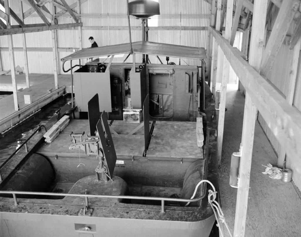
Build development moves on and the hull is beginning to see the addition of more detail. The "rail" earlier cited is proving to be somewhat of a challenge in that the lamination method and the curvature fairing, especially when considering the tapering of the inside curvature to it's desired uniform top dimensions is required. Sections are being made up of the 1/4 inch basswood and dry fitted to the hull. At the moment I am contemplating a build up lamination off the bow (much like a hull frame) and shaping much of it "in hand" so to speak. Pictures of a starboard assembly to follow. While the stern detail is proceeding, without episode, one of our members has begun the aft tripod for the 50 caliber machine gun. We have a decent redrawn and dimensioned picture of the tripod and this is supplemented by one of the archival photos we have in our drop box. However the photo attached does not give sufficient detail in regards to how the gun is mounted to the tripod. If someone out there has a better photo source it would be helpful if you could give us the reference. Posting update 8/11/2019: We are extremely grateful to our colleague on the west coast, Joel L., for supplying excellent archival photos of the gun mount and radios for our model construction. For those interested he has sent an archive reference for study. USN PBR Build Photos.pdf. Included is early build information of the very first PBRs. I am now told that this is a Mark II PBR. Yet I have to believe that the mount save the lower level is of little difference to the Mark I. Joe Mrk I's had a tripod mount
-
Bob thank s for your input. Your input is valued and I stand corrected. I had picked that erroneous information up on another site. It is somewhat ironic that we should receive your input as I was handed a listing of PBRs in either individual or group hands just yesterday. I believe the reference you cite is one in the same source. And this Mare Island reference is one to follow up on. How did that get by us? Again thank you. Joe
-
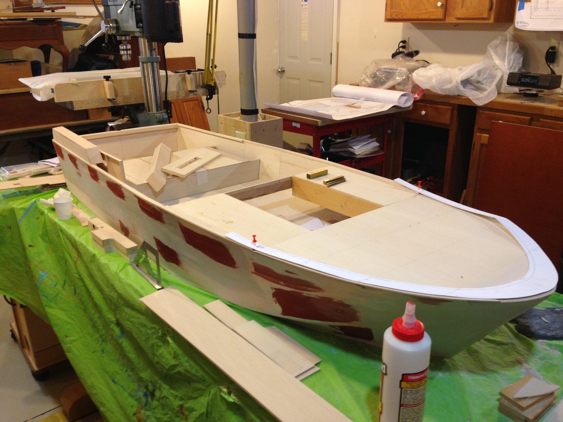
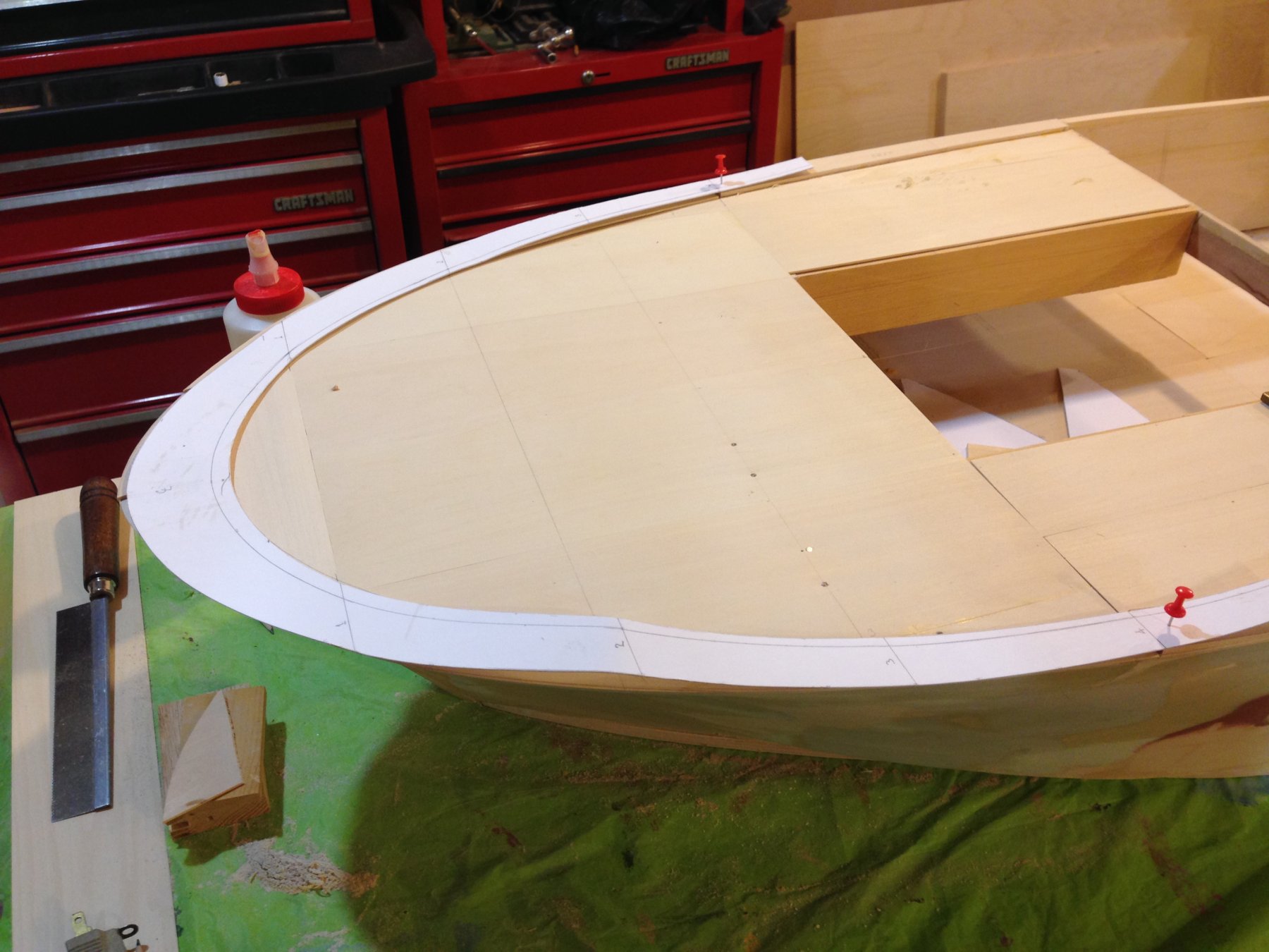
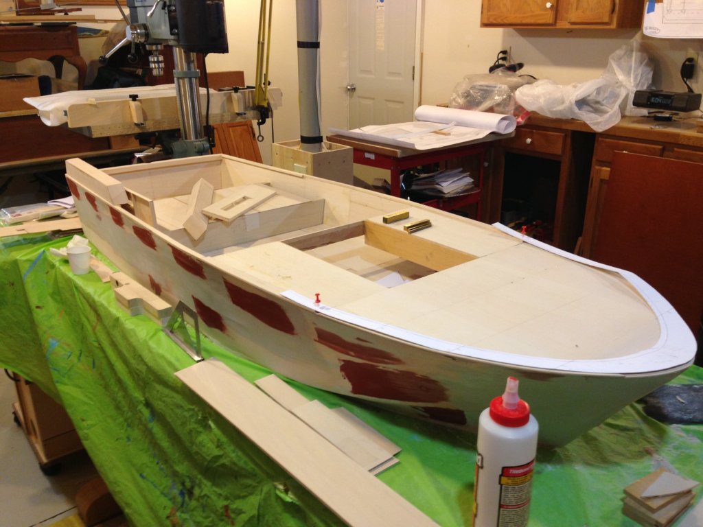
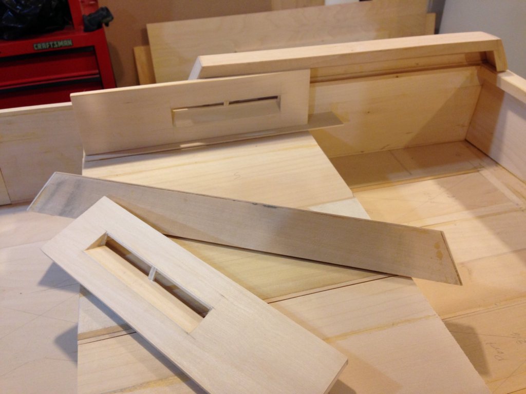
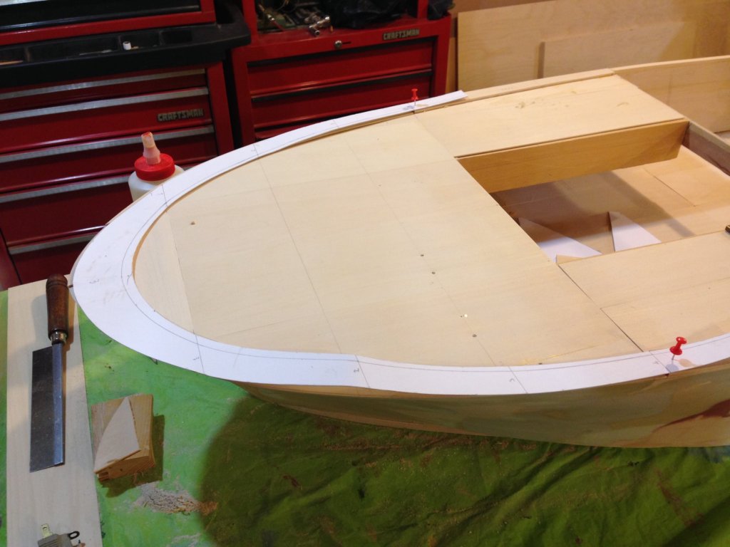
We moved the model to my workshop late last week and we find it much easier to work on. Lighting, room around the model and access to my woodworking tools (both hand and machine) make for smoother operation. Also the storage area at the museum was not air conditioned so summer work there was uncomfortable. The shop, literally is now a "model shop", stays at about 67 degrees with a RH of about 58%. That is the good news! The bad news is I have lost half my work area to this very large model! Once set up here we began anew. The photo of the aft section shows a propped up configuration of the air intake on the starboard side and in the foreground are the sub assemblies for the port side. There will be final fit and set in as soon as we get the "rails correct. The photo of the bow section shows the forward template set on top of the false deck for the "rail" around the deck. It rises from station 11 (at the engine compartment) from near zero height to the bow where it is nearly an inch high. We are planning on building it up out of 1/4" basswood and hand tapering it to drawing measurements. Notice the brass measurement blocks in the background. They will help define that height as we plane down the "rail". We did encounter a problem when we applied the bow template shown in the last photo to the bow area. Somehow our bulkheads at station 3 forward did not capture the flare out at the deck of the hull. It is extreme. No doubt this was to minimize water spray on the open seas at high speed. Underneath the template is a 1/16" thick basswood copy of that template attached to the false deck. It will guide us in fairing in the hull in the aforementioned area. Luckily it is at the correct level of the sheer line. Also the bow itself was found to be more bulbous that our first try at it. Out came the belt sander and now it is near true to form. It is still not ready for the "prom" but maybe just maybe it soon will be. We have called in some volunteers who will be working on the helm area and the forward gun turret. In regards to the latter there were no dimensioned drawings for the detail of that area. So yet another volunteer used the dimensions of the model 50 caliber machine guns to create a working drawing. My earlier lament about "few hands on board" seems to have had some effect. Joe
-
This is just another data point. I cannot refute what has been offered and only add the following. I just took a look at my 1983 built model that is in a case. I used bees wax to coat the lines which were linen. Upon up close inspection with a led flashlight I detect no attraction of dust particles. I will say that I built a temporary case/cover for it while rigging for dust protection. The former residence it was in ( and where it was rigged) had electronic dust control on the furnace and the house dust was minimal. You may want to consider better dust mitigation as it is beneficial beyond ship model rigging. Just a thought. Joe
-
Mystic Seaport has so much to offer that a partial day would need some upfront planning. It is just so engrossing that a "run through" would not do the museum justice. In addition Rt 195/95 traffic can be a challenge at times no matter the day. All said don't miss the museum. Joe
-
I revisited this last post as the reference to the fuel tanks was bothering me in terms of the amount of space forward of the newly placed bulkheads. I stand corrected the fuel tanks are under the deck area where the pilot would stand ( god help those guys as these boats had no armor to my knowledge around the tanks). The open space is actually access to the engines. Joe