Thistle17
-
Posts
1,054 -
Joined
-
Last visited
Content Type
Profiles
Forums
Gallery
Events
Everything posted by Thistle17
-

Cutting Planks
Thistle17 replied to sfotinos's topic in Building, Framing, Planking and plating a ships hull and deck
And all this time I have been thinking I am inept! I find comfort in the responses and of course guidance. On Cheerful there is to be a 1/64 rebate around all gun ports. What I have been doing, before all these very good ideas, was taking my Lee Valley miniature chisel (the 1/8 one) and honing it to near scalpel sharpness. This works most effectively on the vertical rebates before I go any further. Then I gently carve away, bevel side up, the plank ends to the proper relief. For the sills and lintels I do use the chisel, bevel side down to clean up the corners. A very, very sharp chisel will cut the end grain very cleanly (best results can be had with boxwood). Joe -
We are nearing the point where we have to decide on the conformal coating for the hull. It is taking a good deal more attention to fair the hull than we expected. We are still betwixt and between glassing the hull and using some other conformal coating such as they use on "Bitchin Rides" on the Motor Trend Channel for cars. I have sent them an e-mail but they have not responded. The material appears to have a reasonable open time, is yellow in color, and can be leveled with what appears to be large screed boards. It is not Nitro Stan nor is it any of the 2 part levelers that are termed "Easy Sand". These cannot be used over large ares as they set up way too fast. The glassing approach we would fall back on is likely to be the modelers fine mesh cloth with the attendant 2 part gel/hardener. Does any body know the product i.e. the yellow compound used in auto body fairing? I get blank stares at the auto body supply houses. Joe
-
You are gifted Doris there is no question! With that gift you create masterpieces. I do hope you have heirs (s) for the preservation and longevity of your treasures. Joe
- 1,035 replies
-
- 7
-

-
- royal katherine
- ship of the line
- (and 1 more)
-
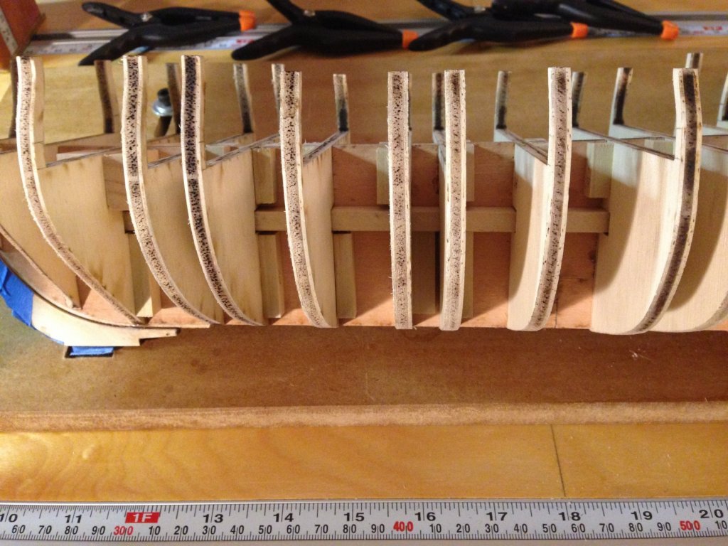
Ship board damage control now finds the bulkheads sanded fair at the keel rabbet and the rabbet strip and keel have been replaced. Time to move on, by attending to the transom frames. These are very delicate members and have to be added somewhat "in the air" as they are attached, one by one to the former sides w/o much structural support. I will describe what I did but in hindsight I will also suggest an assembly method that might be a bit easier. The pictures in Chapter 3 related to transom member assembly aren't too clear but they suffice. Once again I was on a roll with the bulkhead supports I had used for most of the other bulkheads and placed them (the vertical ones) on the aft end of #22. They should have gone on the inside of that bulkhead. This is going to give me a bit of the problem when I have to add the fillers where the stern terminates. However they did give a nice landing area for the inside stern frames that were to be added. I then added the 2 inner most stern members per directions (separated by 1/8 inch spacers along the former) to yield a 7/16" spacing. I liked the support they gave enough to add horizontal members port and starboard to support the remaining stern members. These are separated by 7/16" spacers per directions. All spacers and frame members are glued one to the other across the stern. These frames should be flush with the top of bulkhead #22. I am left with the problem of still having to shape the stern with fillers as one does the bow. This I perceive will be a bit cumbersome. In hindsight I should have re-enforced the bulkhead from the inside as I said and executed the following: On the aft side I would have placed a 3/8" X 1/2" strip across the bulkhead port and starboard side of the bulkhead and then filled in the balance of the stern area with balsa filler. Also for the more fastidious modeler I would be tempted to extend the horizontal legs of each transom frame member such that they can extend forward of #22 bulkhead (slotting this bulkhead to accept the thicker base leg of the frames) and placing those 3/8" X 1/2" horizontal strips on bth sides of the bulkhead (i.e. forward and aft). Joe
-
Jim I did not use the de-bonder as the keel was free about 2/3 of the way to the stern and there was tape wrapping the keel. It just snapped. I will use yellow glue and continue attaching it with the little blocks in the picture. By the way those blocks really make the bulkheads quite rigid. Joe
-
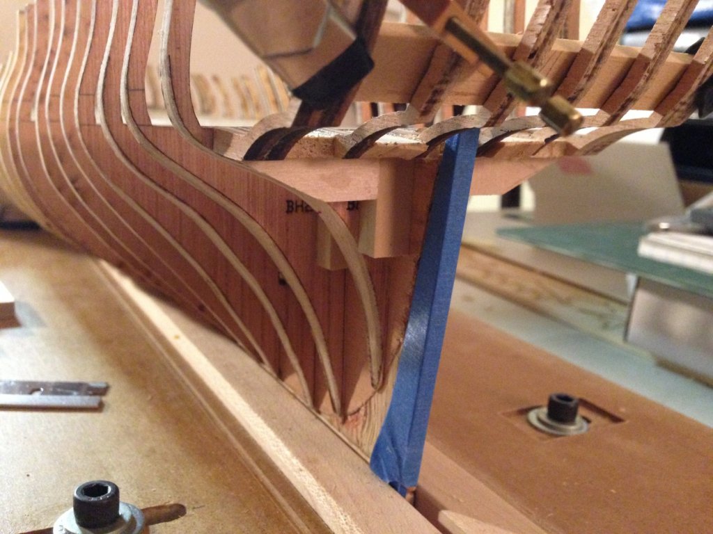
This is a good news, bad news accounting. The Strong museum demo/display was this past weekend. I used Essex for my demonstration for how a kit might begin and managed to assemble about 16 of the bulkheads before the end of the 2 day session. Today I installed the bulkheads 17 through 20. At this point one has to decide if the "strong back" stiffeners are to be added as they pass through bulkheads 3 through 20. They then are glued to the "strong back" and hopefully some of the bulkheads. It turns out this is a annoying task.. I say that because of slight irregularities in the slot of each bulkhead. Theoretically they all should line up and the stiffener just slides through, in this case from the stern, one to a side. If one uses the top of the strong back as the datum slight irregularities occur in the alignment of the slot from bulkhead to bulkhead. As it turned out I had to remove about 40 thousands from the stiffeners. and chamfer the edges to avoid any glue obstructions that may have occurred when the bulkheads were glued in place. Stupidly I used CA to attempt to fasten the stiffeners to the strong back. I used the very thin CA and sure enough some trickled down onto my assembly jig gluing the keel to it!!!!! It took a bit of doing but I was able to extract the hull from the jig but in so doing the keel and most of the rabbet strip stayed behind. After a few moments of self chastisement I discovered it was somewhat of a blessing in disguise. I will have to make a new keel. When using the top of the strong back as a datum and with each bulkhead set flush with it I observed that about 7 of the bulkheads protruded into the rabbet area. At this point I realized it was going to be a lot easier to sand the bulkheads at this point so there was no rabbet overlap prior to the keel repair! That's my good news. Sort of! Joe Note bulhead protrusion at rule 15 3/4 and 16 1/4.
-
Where does this passion and drive come from? It seems every time I check in you have taken another leap forward with great results. Simply amazing! Joe
- 152 replies
-
- 1
-
-
- medway longboat
- Syren Ship Model Company
- (and 1 more)
-
Hannah by Bobby B
Thistle17 replied to Bobby B's topic in - Build logs for subjects built 1751 - 1800
Excellent work BobbyB. It is refreshing to see someone building the Hahn way and fully framed. In regard to the plans are they the Tubman???? And what scale is that? Joe -
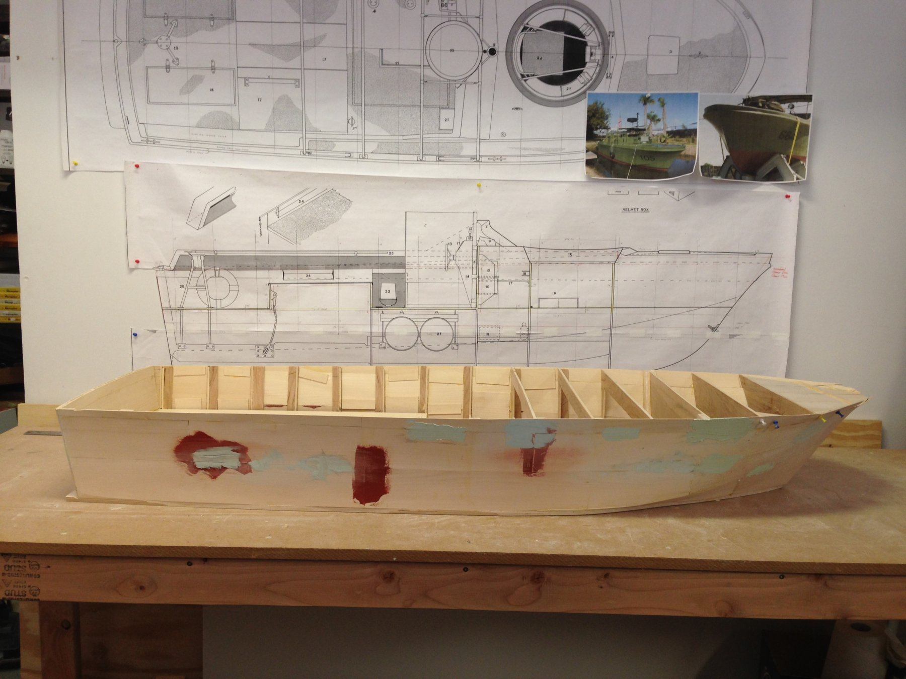
We are only able to muster 2 to 4 hours a week on this build so indeed progress has been less than impressive. Today was somewhat of a milestone however. The "skin" is complete and the sheer line fairing has been made. We are now concentrating on some smoothing and fairing of the hull prior to fiberglass treatment. This seems a most prudent step as one can see the application of Nitro Stan glazing and 3M filler has been required to modify flagrant imperfections. The starboard side is clear evidence of that. Again the use of the 3 inch basswood sheets was thought to be a time saver but it turns out strip planking would have yielded better results. What can't be seen is the inside of the hull. There are many wood braces spanning laterally laid sheets at their junction to stiffen the skin. Luckily this will be hidden once we skin the inner hull. The backdrop is the 1:6 scale Maryland Silver drawings. The photo is from the good folks at Patriots Point South Carolina. Joe

-
New member from Maastricht, The Netherlands!
Thistle17 replied to Anna's topic in New member Introductions
Anna, hello from upstate New York! You obviously have an artistic talent which should support you in your endeavors. I started ship modeling at about your age and the passion has never left. Life events tended to interrupt me at times but as I said the extreme interest and wonder never left. You may be aware that of your gender Portia Takakjian was one of the most prominent illustrators and modelers of modern times. Look her up, her works were impressive. Look forward to seeing your progress. Joe -
Doris I forgot to ask...what are the resistors for near the main cabin...lighting? Joe
- 1,035 replies
-
- 4
-
-
- royal katherine
- ship of the line
- (and 1 more)
-
Doris you have a rare gift that most can not approach in kind. Simply stunning! Joe
- 1,035 replies
-
- 5
-
-
- royal katherine
- ship of the line
- (and 1 more)
-
Buongiorno from upstate New York along Lake Ontario. Picard, you will find the membership and work of this site a most pleasurable journey. Do start a log. It is a way to seek guidance and engage new people all over this world. Joe
-
You wax poetically chief. Great job. I may have missed it are you donating the model for public viewing? Joe
- 31 replies
-
- 3
-
-
- ethan allen
- submarine
- (and 2 more)
-
I have never heard of this Polybak material so will have to inquire further locally. I used to work in engineering at Raytheon in Portsmouth RI on the sonar systems to track these beasts of the deep. Such an impressive vessel. Was in the James River and saw one of these boats come in from the sea with only the conning tower showing, plowing a giant bow bubble. I was just awed by its presence and what a true beast it was. Lovely work and your skill set is impressive. Joe
- 31 replies
-
- 4
-
-
- ethan allen
- submarine
- (and 2 more)
-
Continue to work on preparatory tasks to make the museum assembly proceed without episode. In this vein I dry assembled a gun deck cannon to make sure of its height in relation to the gun ports. With wheels mounted it measures 12mm from floor to top of the carriage of the cannon. The reason for this exercise was to see if the dotted line on sheet 1 of the drawing's gun port framing view, when interpreted as the top of the former and bulkheads, would allow the cannon to clear the gun port sill when the false deck/decking were added. It is indeed the reference I assumed. Now that I have satisfied myself that this is a good datum(that dotted line) I will mark off the sills of the gun ports on the bulkheads in readiness for former install of the gun port elements. Onto the monotonous and dirty task of sanding each bulkhead to remove the char. Since there are 22 bulkheads I opted to use the Dremel tool outfitted with a drum sanding head. At slow speed this is quite effective at the char removal albeit I broke 2 of the upper frame uprights. More work is needed as these frames still fall into the rabbet area. Joe
-
As your Florida neighbor asks "do you ever sleep". You are a prolific and masterful modeler that makes kit modeling come alive. I am amazed at your and others productivity that seem to produce at "warp speed". In that light we have one group member that starts at about 10:00 at night when the house is quiet. If I started at that time I would likely nod off and hurt myself. Wished I lived closer so I could look over your shoulder to understand your work process. Joe
- 359 replies
-
- 4
-
-
- prince de neufchatel
- model shipways
- (and 1 more)
-
In your glory I would imagine Rusty! Outstanding work. How did you maintain any semblance of placement of the holes even with the ribs back illuminated? Joe
-
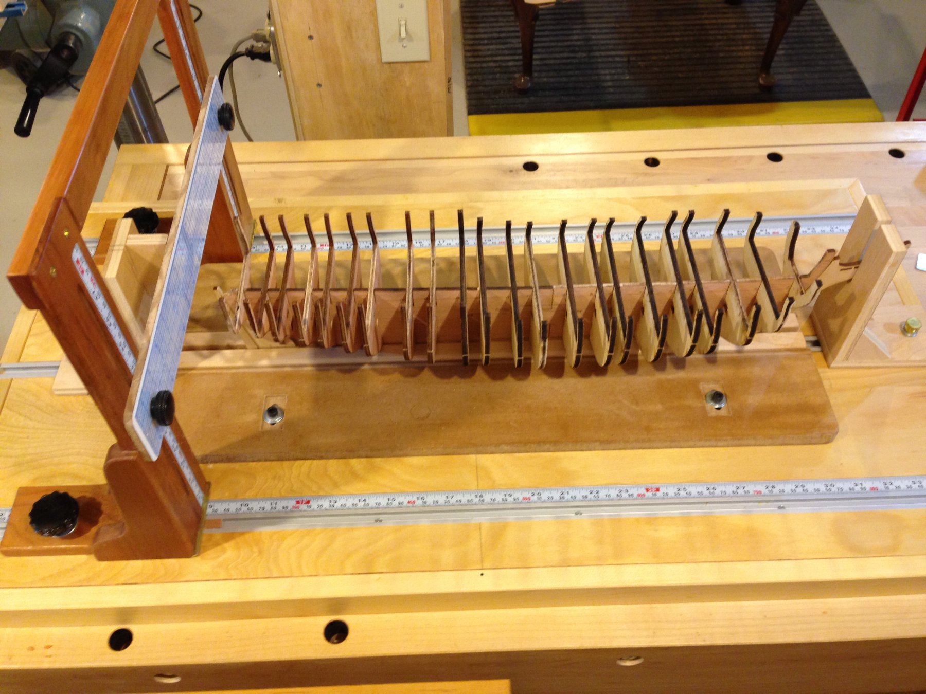
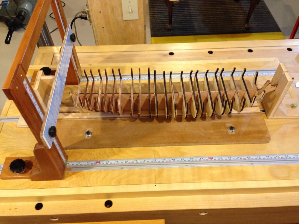
As I said moving on I am preparing for the upcoming January demo/display at the museum. I will be assembling the hull at the museum. In preparation, I have modified my hull building jig (which I had submitted to the MSW site but seems to have disappeared). I will restate this gantry style jig was a borrowed idea from, I believe Ed Tosti, who came up with the design. It is quite effective in holding the former/keel and ensuring the bulkhead perpendicularity can be easily maintained. The one improvement I have made to mine, since its last use, was to add a registration guide to achieve a guaranteed centering of the gantry cross member '0' mark of the center finding ruler that is attached. The gantry lock down was a sloppy fit in the 'T' track making it easy to go astray as it was moved down the length of the platform. Adding a foot to the inboard member of the gantry that rides nicely in the 'T' track slot ensures center registration. It is hard to see in the picture attached as it rides inside the 'T' track afixed to the shoe of the gantry. Only one is needed if it is a good fit. Joe
-
Sam I should have been more discreet in my last entry here. I had no intention of entangling you in this. I just didn't know how many drawing revisions went out in 2015 with the kit. I do indeed have a query into the manufacturer as I feel that is where the dissonance lies, not in your work. If I don't hear from them I will follow the trail with Crane. Nonetheless I am moving off this sub category of the build and onto more of the build. Joe
-
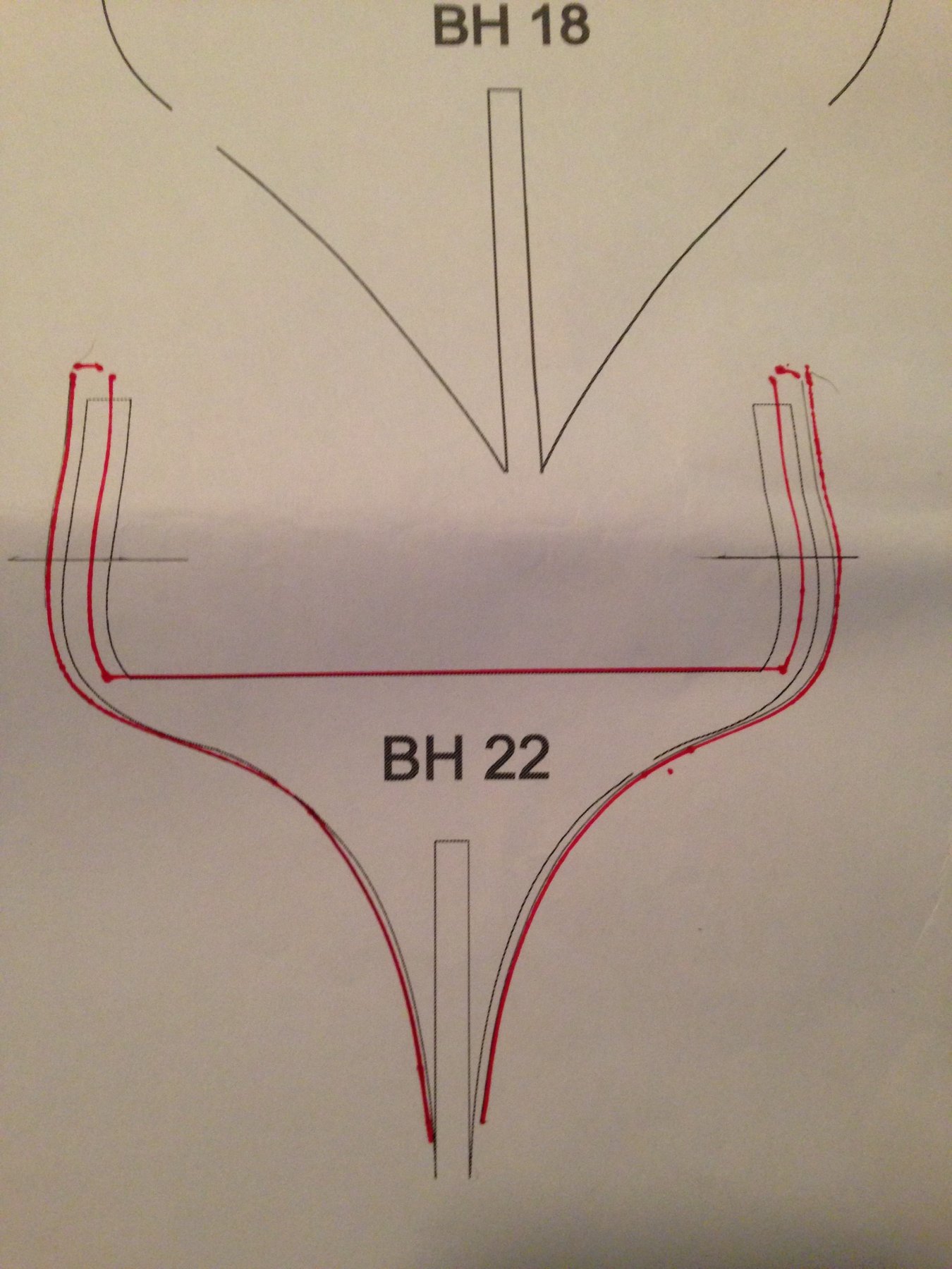
Imagine in the midst of all the craziness that is swirling around us here in the US I find myself obsessing over the accuracy of body plans for a period ship model. I may need to seek therapy soon! In any event I am offering this as my final input and direction forward. I make no claim as to this being the definitive word because what I have decided is based on correlation of/within two sources rather than anything more comprehensive. The two sources are the 2015 release of the Cassano drawing within the kit of the same date and the source mentioned in the Model Ship Builder posting. As I understand it both individuals have designs based on reconstruction of the Hackett plans. Which I further understand that for at least one designer admits his design has some limits. Here is what I did. I replicated the body plan from the Model Ship Builder source. It was of a 1:64 scale. I enlarged it to match the Cassano body plan (1:76.8) and then overlaid the two. They do not match 100% but do show reasonable correlation. The beam is off a bit but that could be magnification errors from web image to screen image to magnification to obtain scale and then to print. The bow stations have decent correlation. Some of the difference might be accounted for by the difference in assigned station lines. The stern section is not quite as much of a match but is somewhat close (see above). Now here is the strange part which I cannot explain. If I use the bow bulkhead from the kit and overlay it on the Cassano body plan it is a very good fit. If I do the similar thing with the stern bulkhead it too is a match. This is what threw me off; placing those same bulkheads on the Cassano sheet that contains each bulkhead shows the deviation earlier noted. Also noted is that the height of the bulkheads seems to be in agreement. In summary I will stay the course with the kit supplied bulkheads and build out from there using not only the Cassano detail drawing but Portia's as well. I apologize if I have whipped interested parties to and fro in this pursuit. And to round out the responses ME got back to me today and further emphasized that sheet 2 of the drawing pack is for reference only and does not reflect the machined parts precisely as the drawing so indicates. So why is that drawing in the set??? Blissfully I move on with all this in the rear view mirror. (12/26/18) Joe
-
Yet a bit more crazy making regarding the accuracy of the kit Essex lines. This morning I remembered this thread on another web site that was done by a Gary M who arduously reconstructed the Essex lines from the AOTS by Portia. His reconstruction to 1:64 scale makes my analysis look primitive albeit the results closely align to what we collectively have been saying herein. I am now wondering if the bulkheads within the kit were a lift of his at the 5/32 scale. Here is the site: http://www.modelshipbuilder.com/e107_plugins/forum/forum_viewtopic.php?16273.30
-
Bob I guess I could have saved myself from a lot of grief had I read your complete log to that point. I will indeed do so from here on in. So in summary there is discrepancy between supplied drawings, manufactured parts and Portia's AOTS book even in the 2015 release. There is some correlation between the 2015 kit drawings and the AOTS reference. So where am I going with the build? Not abandoning it for sure and after some gnashing of teeth will likely do as you have done. I will hold off on gluing in the bow and stern area bulkheads until I have seen what the fairing process yields however. Joe
-
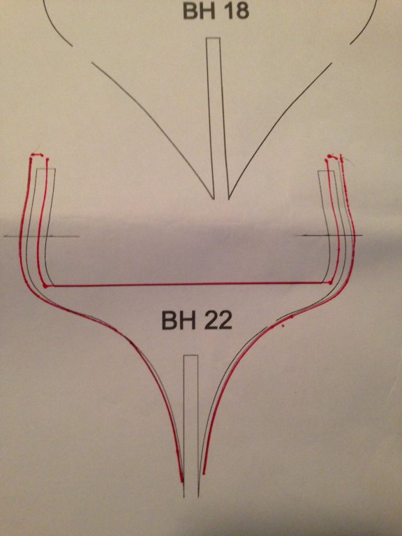
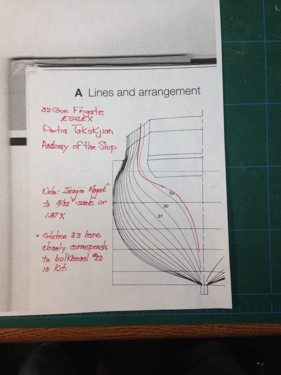
In speaking with the original designer of the kit I am not much further ahead in getting resolution. So while waiting for a response from ME I was prompted by the kit designer to look at Portia's Anatomy of the Ship Essex. On page 34 is a body plan (reconstructed it was claimed from the Hackett drawing). It is not of the same scale but with a 1.87 enlargement I was able to come very close to the kit scale. In addition station 33 on her drawings corresponds very closely to bulkhead 22 in the kit. An overlay of the kit bulkhead 22 (the red outline) shows approximately the same deviation that is shown in the kit drawings of that bulkhead in my last post. Pushing on in pursuit of a satisfactory answer I overlaid the AOS copy onto the kit drawing and there is much more correspondence between them than the part. A bit of crazy making here I know (and my grand kids will never know) but I will. Stay tuned. Joe
-
I am not sure yet Jim. I have an e-mail into the designer and waiting for a reply. And I just thought I would send the text above to Model Expo to ask what they know. Here is a picture of what I think is the worst deviation. Joe