
DONATION DRIVE - SUPPORT MSW - DO YOUR PART TO KEEP THIS GREAT FORUM GOING!
×


ccoyle
-
Posts
10,519 -
Joined
-
Last visited
Content Type
Profiles
Forums
Gallery
Events
Everything posted by ccoyle
-
 Okay, someone is gonna ask: What kits might those be?
- 440 replies
-
- 1
-

-
- niagara
- model shipways
- (and 1 more)
-
Short answer: no. But they are helpful when it comes to keeping everything square and providing a base layer for planking.
-
Very neat work!
-
😳😳😳
-
Looking for advice on starting a build log
ccoyle replied to Ken_2's topic in New member Introductions
Just follow the directions here. The directions are pinned in each build log category. Cheers! -
Nice job on your first model! Nothing breeds success like success.
-
Images of incomplete builds and loose photos get culled on a regular basis (where 'culled' = whenever a moderator gets around to it!).
-
I've always had a bit of a soft spot for Arizona because I was born there (the state, that is) and because I built the ancient Revell box-scale kit as a kid. Good luck on your project!
-
This one is looking pretty impressive, both size-wise and finish-wise.
-
The Sinking of the Bismarck ... with LEGOs ...
ccoyle replied to uss frolick's topic in Nautical/Naval History
I'm even more impressed now! -
I love sailing prams! Good luck with this excellent kit.
-
It's true that if you look at real copper sheathing on extant sailing ships, such as the Chas W Morgan at Mystic, the nailing is barely perceptible, if at all. I've seen good-looking coppered hulls done with copper tape, either cut into individual plates or simply scored, and with the copper simulated by using metallic copper spray paint (I think some BlueJacket display models have been made in that fashion). In my mind, you are justified in using whatever method looks good to you.
-
I think this is an individual thing rather than one of cultural difference. Woody Joe kits, for example, are pretty standard POB affairs, and I have seen many scratch builds done by Japanese builders that are done using the usual POF methods. The Okumoto lineup is designed to make POF style models more accessible to average modelers (like me). They are indeed more like putting a puzzle together than doing a true POF model, but that's fine for me -- I like putting puzzles together and have neither the tools, space, nor skills for doing standard POF builds. If all goes well moving forward, I plan to add a few "personal touches" to this model to make it a small step up from an out-of-the-box build. Stay tuned!
-
I have all of the frames completed at this point, and I looked up Mr. Okumoto-san's videos on YouTube. Unfortunately, he did not provide any instruction on fairing the frames; he might have mentioned fairing, but of course the narration is in Japanese, so I had no way of knowing. Interestingly, though, the frames in the video did look like they had been faired, so I'm leaning toward doing the interior fairing before mounting the frames, because as Jason has noted, it will be near impossible to do the job once the frames are glued to the keel.
-
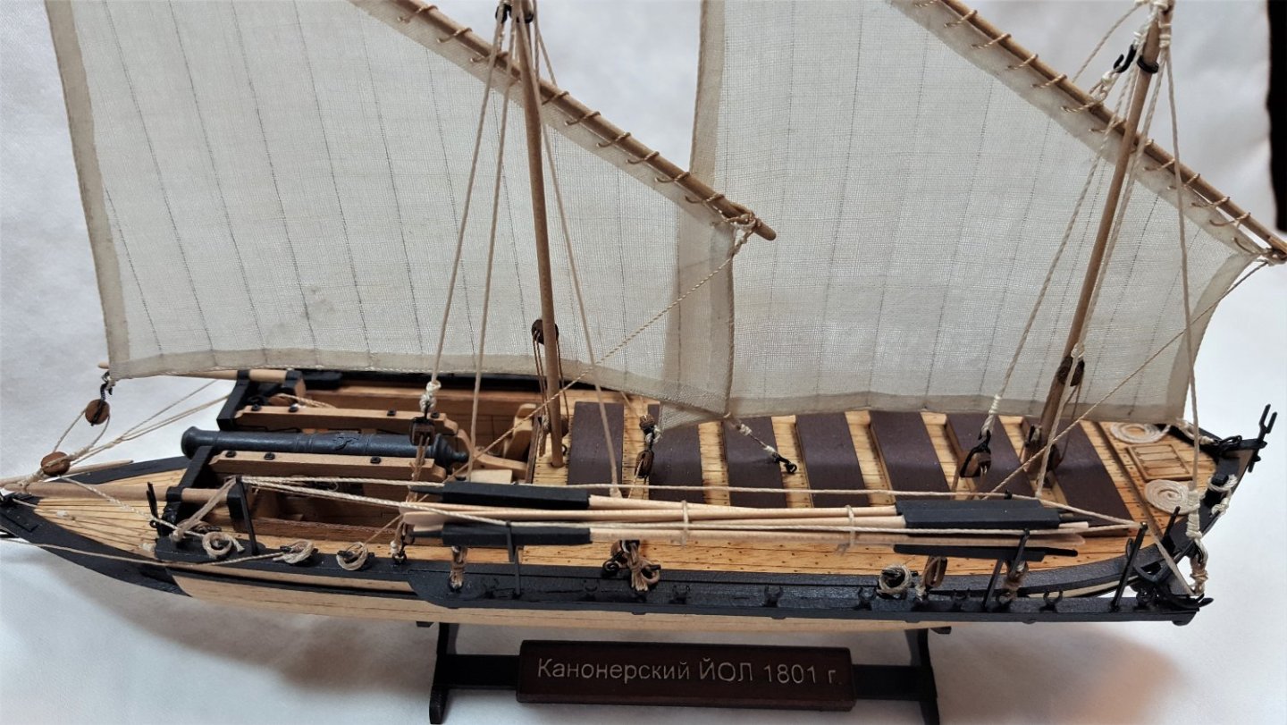
Good decision. I have always opted out of sewing of any kind on my sails for exactly this reason. Correctly scaled stitches are simply impossible to replicate at the scale modelers work in (though I do not think they necessarily look bad if a modeler decides to include them). With care, it is even possible to glue the bolt ropes directly to the edges of a sail, as you can see in the accompanying image. You are approaching the finish line on this one!
-
True dat. I think it is more commonplace for kits to include sailcloth and patterns rather than sewn sails, but yeah, there is no industry standard on this.
-
I laughed when I read that, but only because once upon a time during one of my extremely limited number of ski trips, I had a similar fall -- went off a groomed trail into some deep powder. Skis plunged deeply into the soft powder, followed quickly by upper torso/face. No injuries, thankfully. Of such episodes are memories made!
-
Intro to Card Models Pt. IV: Tools & Other Supplies
ccoyle replied to ccoyle's topic in Card and Paper Models
Thanks for that tip! For hole punching, I acquired a Japanese screw punch a couple of years ago. It is likewise a very useful tool, though when shopping for one, one needs to be careful not to end up with one of the inferior Chinese-made clones. The confectionery tools you linked to are very similar to the dapping tool set I have described in some of my build logs. It's good to know that modelers have options when it comes to adapting a variety of tools to our particular art. Spotting tools used by manicurists are similarly useful. -
You can always get a member's attention by using the @ symbol. Example: Hey, @Ab Hoving, do you have any input on this discussion?
-
Since the instructions call for scribing, that means that the supplied deck material is already the correct scale thickness. Adding a layer of popsicle sticks will make your finished deck too thick. If anything is to be added at all, it should be a very thin veneer (such planking is available if you shop around). I did scribing on my two Midwest kits, and it does not look bad. It is also pretty easy to do.
- 55 replies
-
- 3
-
-
- sharpie schooner
- Midwest Products
- (and 1 more)
-
The Sinking of the Bismarck ... with LEGOs ...
ccoyle replied to uss frolick's topic in Nautical/Naval History
Very dramatic and well done! -
I assume you are speaking of the vendor at Shapeways? I have ordered from a different Shapeways vendor without issue, other than the slow delivery time coming from Canada -- not the vendor's fault. Of course, that experience may not hold true for Model Monkey -- have you tried an internet search for other builds that have used his products?
-
Always be mindful that a glass case of the size needed for Snake will be quite heavy.
- 1,144 replies
-
- 2
-
-
- snake
- caldercraft
- (and 1 more)


