HOLIDAY DONATION DRIVE - SUPPORT MSW - DO YOUR PART TO KEEP THIS GREAT FORUM GOING! (Only 75 donations so far out of 49,000 members - C'mon guys!)
×


ccoyle
-
Posts
10,459 -
Joined
-
Last visited
Content Type
Profiles
Forums
Gallery
Events
Everything posted by ccoyle
-
 I have thought about that, but ultimately it would be an exercise of little value. If the kit engine does prove to be smaller and thus a better fit, that would suggest a wiser course would be to use the kit engine -- all 250+ parts of it. 🤮 And of course that would mean a not inconsiderable sum spent on after-market parts would be down the proverbial toilet with no return on the investment. No, I plan to start by finishing the cowling first and then calculating how much of the resin engine I will need to modify or remove in order to make it fit. As I said, the cowl opening is narrow, so it's possible that most or all of the surgically altered parts will not be visible. One step at a time!
 -
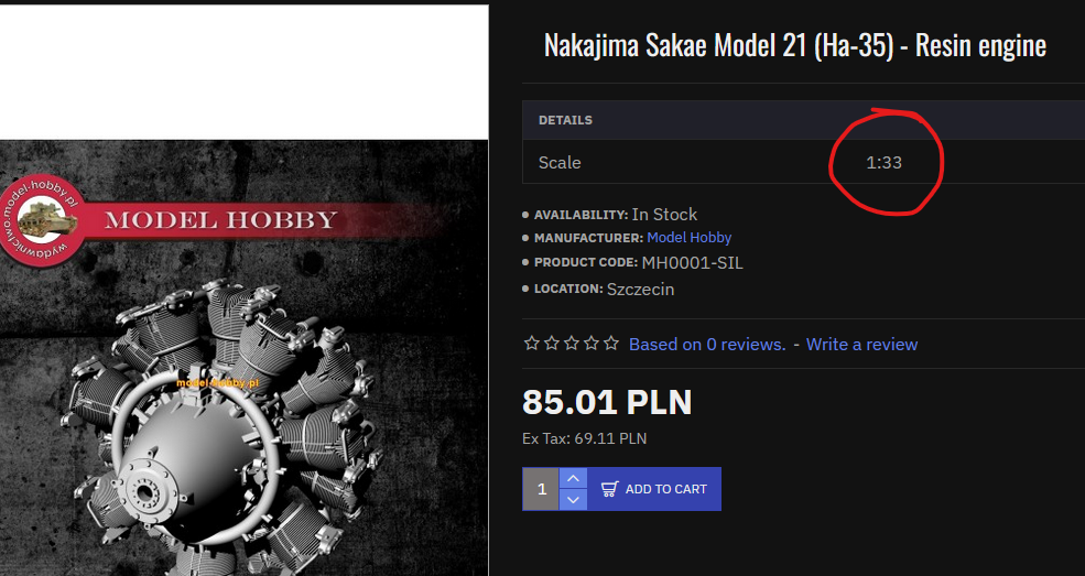
I'd be a little annoyed if that were to prove to be the case, since the part is marketed as being 1/33 scale.
-
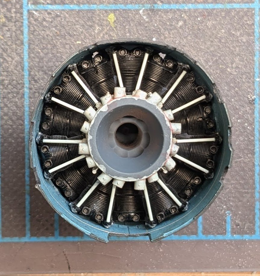
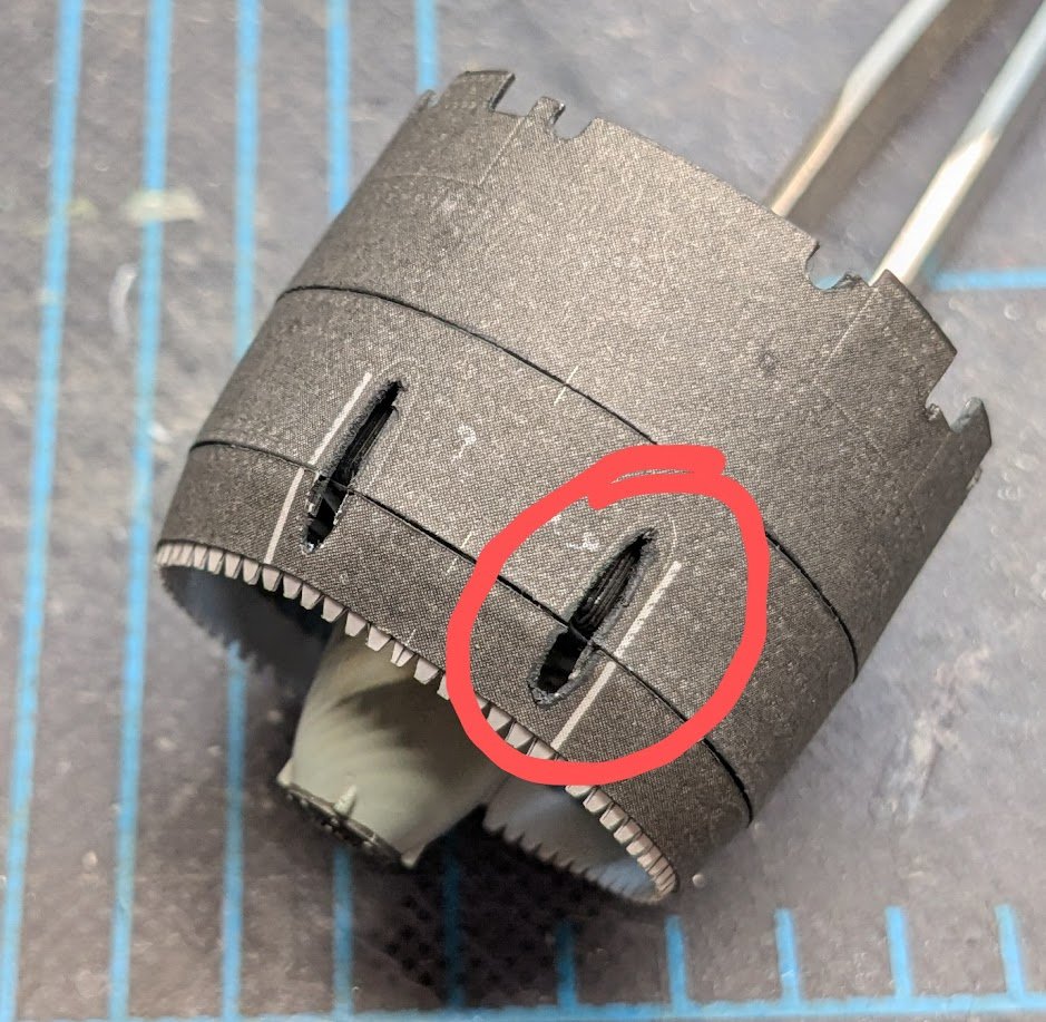
Trouble is brewing . . . First off, the resin engine is a very, very tight fit. This fact is made worse by the fact that the cowl's diameter decreases as successive rings are added. To get the engine to fit into the first three rings, I had to file off the top halves of the front cylinders' valve covers. But it gets worse . . . The engine itself is not the only thing that has to fit into the cowling. There's also the machine gun channels, and as you can see in that first picture, there's no room for them. In this next photo, you can see that cylinder heads more or less completely block the front openings for the guns -- and that's without the channels being installed. There's also an air duct that needs to fit in there as well -- don't ask me how. I'm quietly wondering whether this engine isn't actually a 1/32 scale engine rather than 1/33. It's not out of the realm of possibility.
- 112 replies
-
- 14
-

-

-
Purely coincidence! I just happened to be browsing through the card logs today and noticed a few that had been quiet. I have taken the liberty of marking this log 'terminated'. We do that rather than simply deleting logs, because even unfinished logs contain information that may be of use to someone.
-
Good to hear, Jeff! My retirement is still a few years down the road -- but I can dream!
- 37 replies
-
- 1
-
-
- Baltimore
- heinkel models
- (and 2 more)
-
Welcome aboard!
-
Whatever became of this project? Did you finish it?
-
Hey, Olli, how is this build coming along?
-
Just noticed that there was no update for May -- how's this one coming along?
-
A very attractive model -- well done!
-
Not a 1/200 model, but here's a finished 1/350 Yamato build log to inspire you.
-
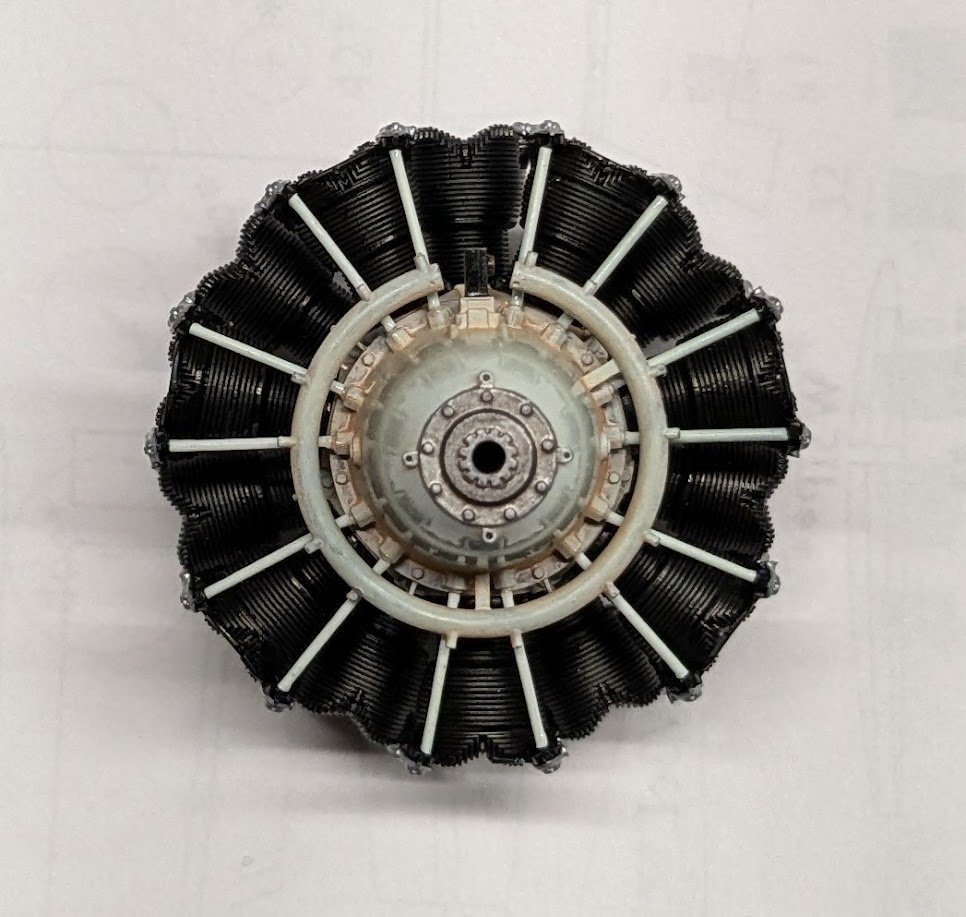
Thanks for the compliment! I thought about doing just as you suggested, but most of the photos of Sakaes I have seen online do in fact have jet-black cylinders, so I won't worry too much about it. The finished cowling will have a rather narrow front opening, so between that and the propeller not much of the engine will be readily visible.
-
The Mossy Shipyard by Bryan Woods - 1:1
ccoyle replied to Bryan Woods's topic in Non-ship/categorised builds
And if you fail at that mission, He will give you an impenetrable Southern Woods mass of carpet, walls, and ceiling, but no doors! -
The engine block and cylinder heads are now together -- still have push rods and wiring left to do. As i mentioned earlier, there are no intake pipes for the engine. Those would potentially be visible on the finished motor, but they would be a huge pain to make from scratch, so I probably will not add them. With the help of a fellow card modeler from Poland I was able to solve the riddle of how the first pair of inner and outer cowling rings went together. The eventual mating of the cowl and engine required removing the entire center portion of the cowl bulkhead, as shown. The engine will have to go into the cowl and then the bulkhead added afterward, but that is down the road a bit.

- 112 replies
-
- 16
-
-

-
Well done!
-
Leaving one's card models out where a fur baby can access them can produce the same result.
- 288 replies
-
- 9
-

-
- Card
- Pre-Dreadnought
- (and 3 more)
-
I think you are speaking about the gun port lining? Personally, I would omit it, as it makes the port too small. The gun crew would have very little room to traverse or elevate the gun, nor to aim it.
-
Nice work, Craig!