HOLIDAY DONATION DRIVE - SUPPORT MSW - DO YOUR PART TO KEEP THIS GREAT FORUM GOING! (Only 75 donations so far out of 49,000 members - C'mon guys!)
×


ccoyle
-
Posts
10,459 -
Joined
-
Last visited
Content Type
Profiles
Forums
Gallery
Events
Everything posted by ccoyle
-
 Welcome aboard, and very nice work!
 -
Welcome aboard!
-
Plans needed: Constructo Enterprise 1799
ccoyle replied to Gershon B's topic in Wood ship model kits
Since your query is in regard to a specific kit, I have moved the topic to the kit discussions are. Hope you find what you're looking for! -
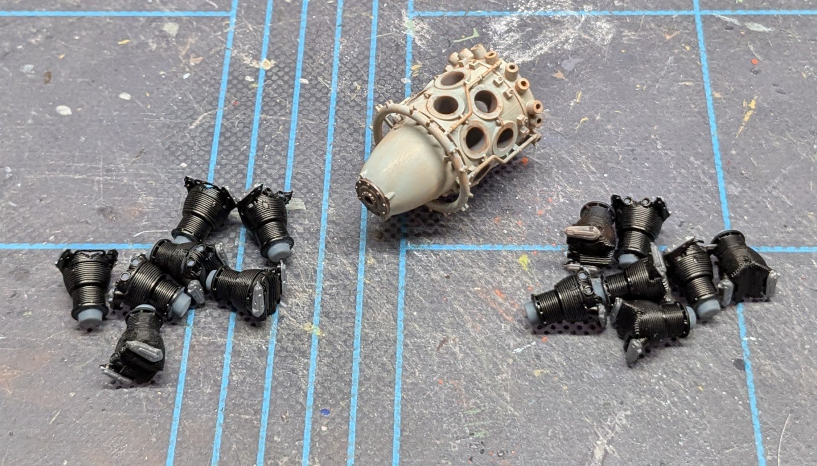
The parts are now separated from their sprues. Most online pictures show black cylinder heads with aluminum valve covers. Blocks and gear boxes are shown in varying shades of bluish-gray, from light to dark. I have settled on a light blue shade and have grunged it up with weathering chalk. I have tried several different washes and chalks to try and highlight the cooling fins, but nothing has been satisfactory so far.

- 112 replies
-
- 15
-

-

-
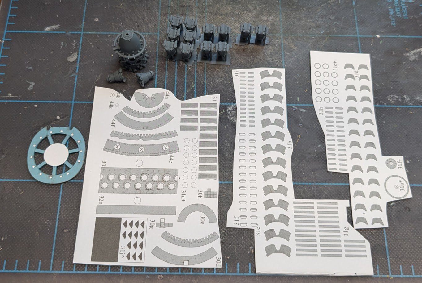
I have started in on the Sakae-21 engine, which is going to be real challenge. The paper engine supplied in the kit consists of 250+ parts, not including the exhausts, so one can understand why I opted for the resin engine, which consists of only 15 parts, not including the push rods and exhaust stubs. Some hurdles to overcome: Liberating the resin parts from their sprues. This takes forever because of the care that must be taken when handling the brittle resin. The resin engine includes a distributor ring, but obviously no spark plug wiring. Since it seems dopey to include the former without the latter, I will need to add the wiring. Which leads us to the next hurdle . . . . . . the resin cylinder heads differ slightly from the Sakae-21s I am seeing online, which means there will be a little guess work about where to attach the spark plug wires to the cylinder heads. The kit includes a bulkhead that forms the shape of the cowling. Most of the kit engine block attaches to the front of the bulkhead, but a small slice goes on the back and acts as a spacer between the fuselage and engine assembly. This is obviously different than the structure of the resin engine, which means I'll have to remove the white portion of that bulkhead and pass the resin block through it. I'll have to position the 'spokes' of the bulkhead precisely on the engine block so that the block is in exactly the same position between the fuselage and cowl opening as it would have been when using the card parts. The resin exhaust stubs (not shown) are grouped together differently than is shown in the kit's build diagrams; the resin stubs are molded together in groups of three or four, while the aircraft depicted in the kit has mostly individual stubs with a coupe of paired sets. I have not been able to find any pictures of any aircraft powered by Sakae radials that have their exhaust stubs grouped in the manner provided by the resin set. Most likely I will have to cut apart the resin stubs (which is tricky, considering how brittle the resin is) and mount them individually. On the kit bulkhead, you can see a ring of 14 white dots -- these are where the kit's printed stubs should attach. The resin stubs are designed to pass all the way forward into their respective cylinders. I have an idea for how to pull this off relatively painlessly, but the plan hinges on the separated stubs having the proper bends to reach their cylinders. In any event, most of the stubs will not be visible once the cowl is on, so a second option would be to simply use only the portion of each stub that is externally visible. Speaking of attaching to cylinders, the resin kit does not include the air intake pipes. This is not a huge problem, since they would not be visible on the finished model anyway. Finally, I'll need to settle on a paint scheme. The Sakae-21s seen online exhibit a variety of schemes. Ultimately, the idea here is not to replicate a Sakae-21 in every possible detail (I'll leave that to the plastic fanatics), but simply to up the 'wow' factor a notch on the finished model. Hopefully I can accomplish that while maintaining my sanity.
- 112 replies
-
- 15
-
-
-
Click here to check out this book. I have the Alert title from the same series, and it includes rigging tables. I would assume that other titles in the series do as well.
-
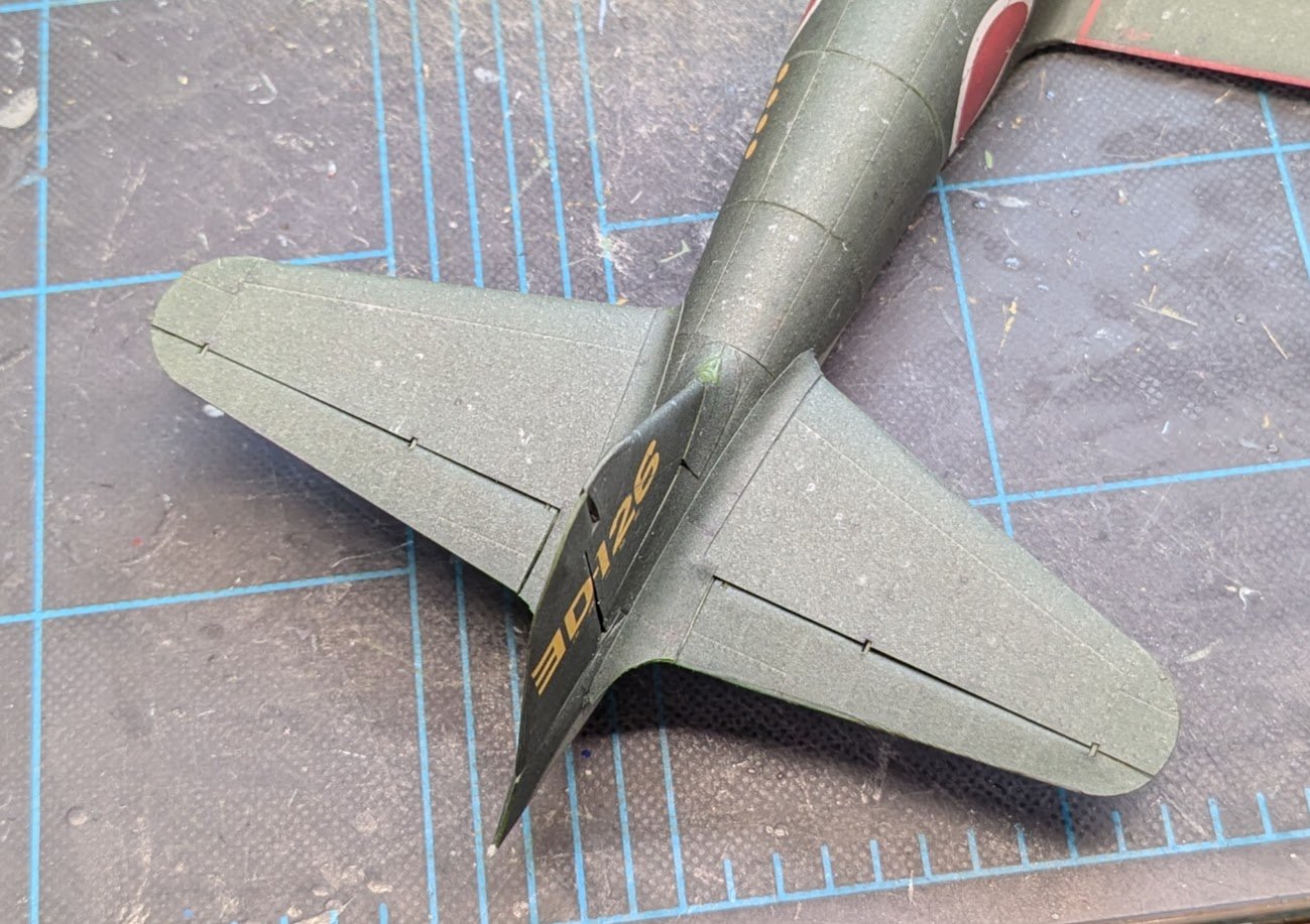
Stabilizer fillets and elevators added. A curious factoid: the diagrams show a trim tab on the rudder which the kit parts lacked. I did some web searching to see which was correct -- turns out the A6M2 had a rudder trim tab, but the A6M5 did not.
- 112 replies
-
- 14
-
-
Nice work, Andy!
-
Welcome back! In some respects, the first planking is the hardest. You have gotten the second layer off to a good start!
- 139 replies
-
- 1
-
-
- Lady Nelson
- Amati
- (and 2 more)
-
Intriguing!
-
Condolences on the loss of your pet. It's not easy to say goodbye.
-
Welcome aboard!
-
Check out these offerings from Woody Joe: https://www.zootoyz.jp/contents/en-us/d2045761086_Japanese-Sailing-Ship-model.html
-
Good luck on your project! I built Chris' first iteration of Sherbourne, which he designed for Caldercraft many moons ago. The new design is much more beginner-friendly.
- 9 replies
-
- 3
-
-
- Vanguard Models
- Sherbourne
- (and 1 more)
-
Sometimes these older 'beginner' kits can be quite a challenge! Good luck on your project, and don't be afraid to ask for help.
- 6 replies
-
- 1
-
-
- St Helena
- Constructo
- (and 1 more)
-
Hull Finishing Examples
ccoyle replied to Burgundy's topic in Painting, finishing and weathering products and techniques
I hope you have a copy in hand? I checked at ME this morning, and their links to the practicum chapters were broken. -
Hull Finishing Examples
ccoyle replied to Burgundy's topic in Painting, finishing and weathering products and techniques
@Chuck has achieved some excellent finishes with basswood, and he has described his methods in several practicums. He'd be able to direct you to them more readily than I can. -
Hi, @Bontie. I have moved your query to the kit discussions area. To get an answer, you will probably need to be more specific about the "references" you refer to. Hope you get help soon!
- 1 reply
-
- 1
-
-
Check out this nearly-completed build log:
-
Witam! I am a fellow fan of card modeling, though my work does not approach the level of the Polish masters. Glad to have you aboard!