HOLIDAY DONATION DRIVE - SUPPORT MSW - DO YOUR PART TO KEEP THIS GREAT FORUM GOING! (Only 75 donations so far out of 49,000 members - C'mon guys!)
×


Cathead
-
Posts
3,502 -
Joined
-
Last visited
Content Type
Profiles
Forums
Gallery
Events
Everything posted by Cathead
-

Steamboats and other rivercraft - general discussion
Cathead replied to Cathead's topic in Nautical/Naval History
So I'm sad to say that I was underwhelmed by the recent talk. It was probably fine for an audience that was new to steamboats, but the presenter's knowledge base was pretty shallow and he made a number of mistakes during the presentation. The following Q&A made it even clearer that he didn't really understand the topic. I've read his book, and found it disappointing as well. I was hoping the talk would at least share some new information, insights, or imagery, but it was pretty bland and rambling. If others felt the same, I'm sorry for wasting your time by bringing it up.- 281 replies
-
- 2
-

-
- Steamboats
- riverboats
- (and 3 more)
-
Thanks for the kind comments! I just revised my earlier post for clarity, since I kept using "wedge" to mean "chock", which could be confusing as "wedge" means the pieces the initial capstan barrel was supposed to be made of. Also, @Siggi52 has been finishing up the double capstans for his unbelievably beautiful HMS Tiger (seriously, I'm not being hyperbolic here), and I thought it was interesting that he, too, seems to have built his capstans by filing down a round dowel where necessary. Just thought I'd share these photo for anyone considering doing it this way. Otherwise it's neat how similar his capstans are to this project's (though not surprising given the research that's gone into both): I hope he's ok with me sharing these, I think they're a great reference and if you're not already reading his log, you should be! Coming soon, an update on building the capstan head.
-
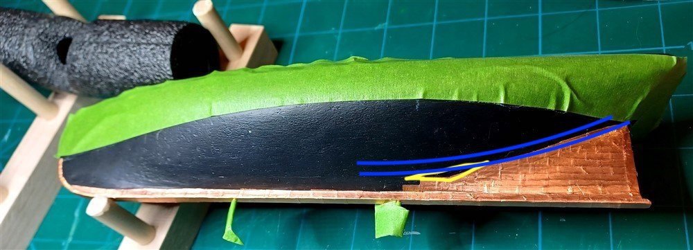
Lynn, this may be too picky (and too late), but it looks to me like the drawing shows that the hull-length coppering is meant to make a sweeping curve that follows the natural curve of the hull and blends gradually into being parallel with the keel, not a straight line that ends in a specific angle with the run of the keel, as marked up in blue below: It's not a big deal now, but as you keep going up I'm concerned you'll have more trouble with that angle and it'll become ever-more awkward and noticeable. I assume the next lines of coppering follow that initial curve, so without having to redo anything, I think you could fix it by making sure to lay the next one in a curve and just insert a small filler plate where there's a gap between the curve and the angle (yellow below): Forgive the rough mark-up but hopefully it illustrates the point? Full disclosure, I've never coppered a hull, I'm just going on what the plan you displayed seems to show and my intuition as to how any linear feature (whether planking or coppering) will run naturally over a curved hull. Feel free to disregard, just wanted to make the suggestion. Happy to hear that I'm wrong from someone with more experience laying out coppering belts.

-
Wow, that’s a significant improvement! I agree that I can see a slight extra gap after the A but the rest is awesome. And since A in that font is broader than average and creates more space around itself anyway, I don’t think it matters. One (of many) things I’ve learned in modeling is that individual “wrong” details can bug you during construction but completely vanish in the overall model’s effect.
-
I've never built this kit so any advice I can offer is more general. Actual builders like Bob will certainly be more directly helpful.
-
I suggest reading this link, posted at the top of this section:
-
Looks lovely so far! This is a challenging but rewarding project (at least that's been my experience so far).
-
Nice start, and I think we've all been there at some point with frustration over a missing/lost part. As for adhesives, basic wood glue works quite well for most wood-on-wood contact and will give you a longer work time.
-
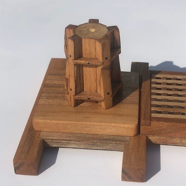
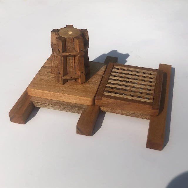
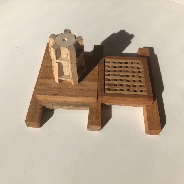
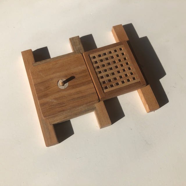
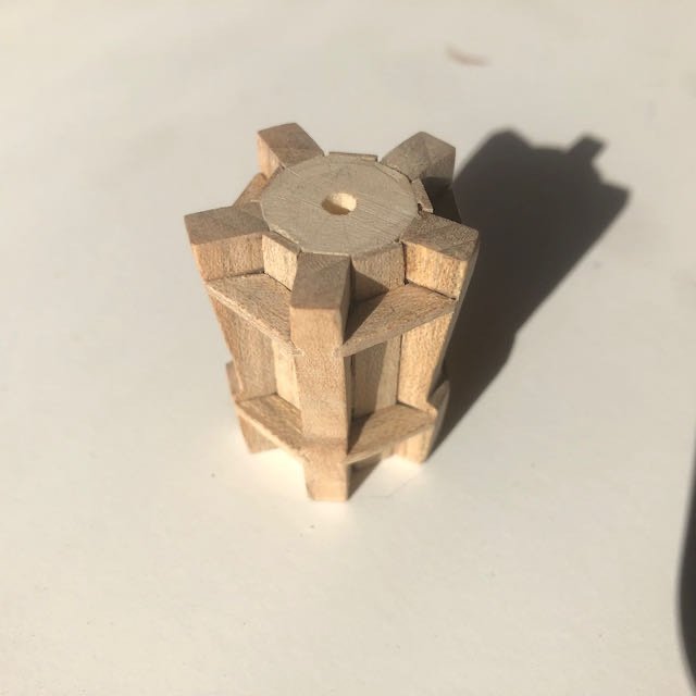
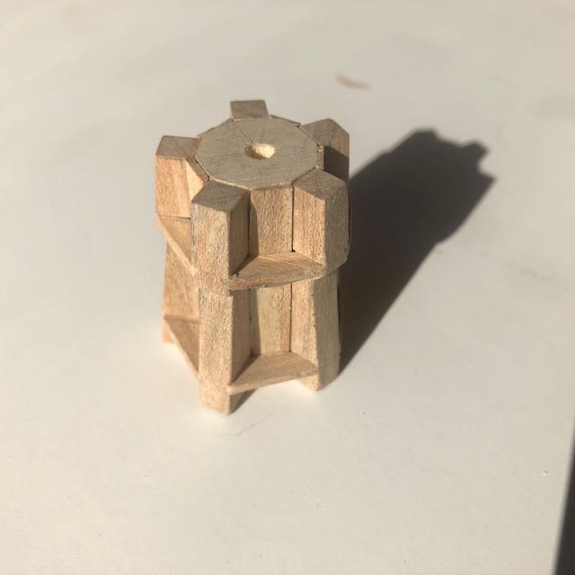
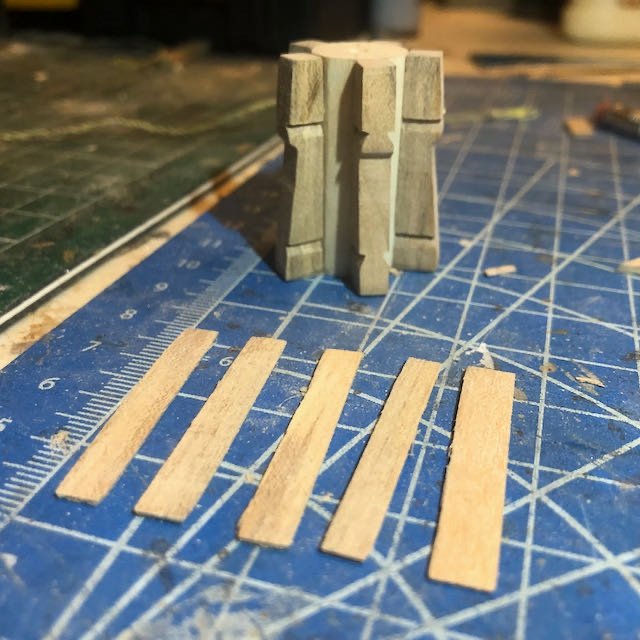
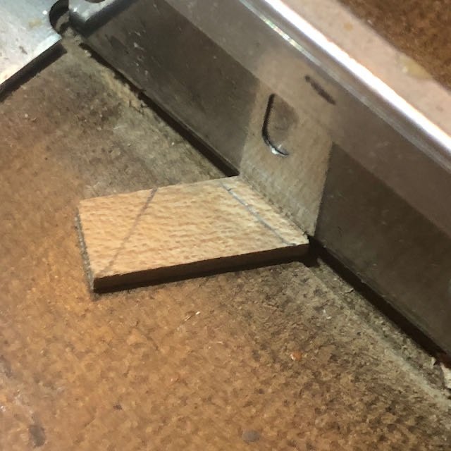
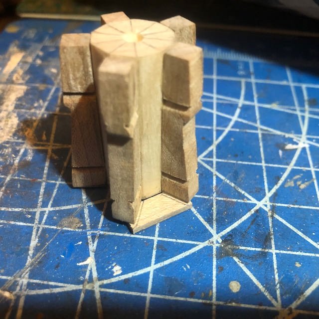
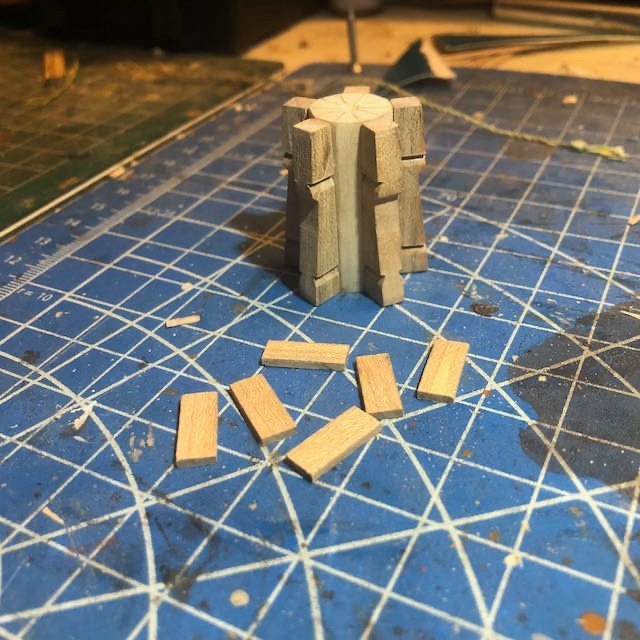
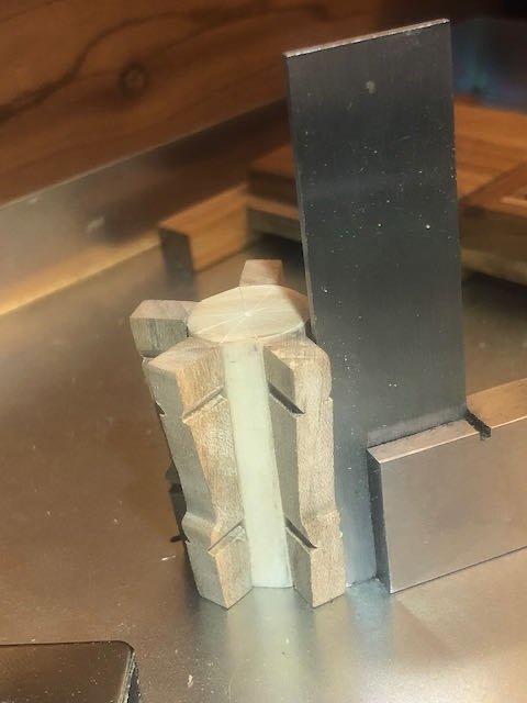
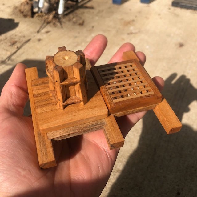
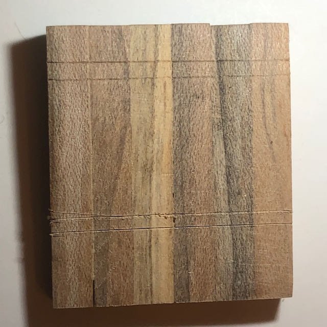
Assembly continues. With the whelps shaped, I glued them onto the barrel, using a square to get them as straight as I could: Then it was time to make the chocks, which form the two rings that fit between the whelps (what the side notches were cut to hold). Since my assembly wasn't perfectly symmetrical, I made each of these by hand to fit its specific slot. For each chock, I traced the outline of the angle between the two whelps, then cut a wider version to allow for the angled edges that fit into the notches: I then used a combination of knife and sandpaper to get the angled edges right, and test-fit the chocks. I made sure to label each chock and its corresponding location on the barrel: By now, readers who have been following this very closely are jumping up and pounding on their desks, screaming "Wait, Cathead, you've forgotten something!" Indeed, as I realized just as I was applying glue to the first chock. As you may recall, the plans show a barrel made out of wedges, creating alternating raised and lowered surfaces; the whelps fit into the recesses so there is a raised surface between them. Since I made my barrel by shaping a dowel instead, my plan was to simulate those raised surfaces with a thin veneer, which would also keep all the outer surface looking like maple. I came very, very close to forgetting this step because, of course, it wasn't in the instructions (being my own invention). So I set my chocks aside and did the veneer by cutting five thin sheets of maple and custom-fitting them between the whelps: With that done, I reshaped the chocks I'd already made (since they now needed to be smaller) and made the second ring. Once these were all glued in, I sanded them to shape, following the instructions in making the upper ring a bit convex and the lower ring a bit concave. Top view: Bottom view: You can see how the veneer simulates the raised wedges. I'm pretty pleased with this approach, it was much easier than making wedges (at least for me). The next step was to get the barrel mounted properly on the platform. Here I discovered that the 3/8" hole I'd initially drilled wasn't perfectly straight, making the capstan sit at an angle. Sigh. So I fixed this by using a 3/8" plug to fill the hole and instead drilling a new, smaller hole within that and fitting a smaller dowel as the actual axle, which was also easy to drill into the capstan base: So here's the raw capstan set on the base: And here it is with a coat of wood oil, and with the bolt holes drilled and filled with small bits of wire: You can see why I did the veneer; the dowel comes out a completely different color than the maple and I didn't want that showing through between the whelps, even if I didn't care about the raised surface (which I did): And a final photo as a reminder of 1:24 scale: On to making the drumhead...
-
I've built the Model Shipways version of this craft, so don't have direct experience with the OcCre version. I don't understand the pore-filling lacquer either. While I don't claim to be an expert, I've built a variety of wooden kits and scratchbuilds and never used anything more than basic wood oil or stain as a finish. Personally I don't like the shiny look of lacquer/varnish on a model but that's builder's choice. One thing I will say is that it's often easier/better to stain pieces before using any glue on them, as glue doesn't take up stain the same as raw wood, so any seeps or spills will show up if you stain something after assembly. On the other hand, prestaining means that if you need to sand or alter something later, you can get an uneven finish. I was surprised they have you glue the decking straight to those frames, since the frames are clearly plywood and wildly out of scale, but I guess that's their shortcut to make the model easier to build. Not having built this kit makes it hard to be more helpful, but I'll try if you have further questions!
-
Cool! If you're using a 1:48 kit, how are you adapting that to 1:16? Or is this a scratchbuild and you're just consulting the design of that kit?
-
I can sympathize, I have yet to build a kit with really good instructions. Hope this one fits your bill!
-
Echo by tlevine - FINISHED - Cross-Section
Cathead replied to tlevine's topic in - Build logs for subjects built 1751 - 1800
Looks very nice, I'll be jumping in late. Cross-sections have always fascinated me as someone who likes to know how things work. -
Steamboats and other rivercraft - general discussion
Cathead replied to Cathead's topic in Nautical/Naval History
That is so cool, thanks for sharing!- 281 replies
-
- 2
-
-
- Steamboats
- riverboats
- (and 3 more)
-
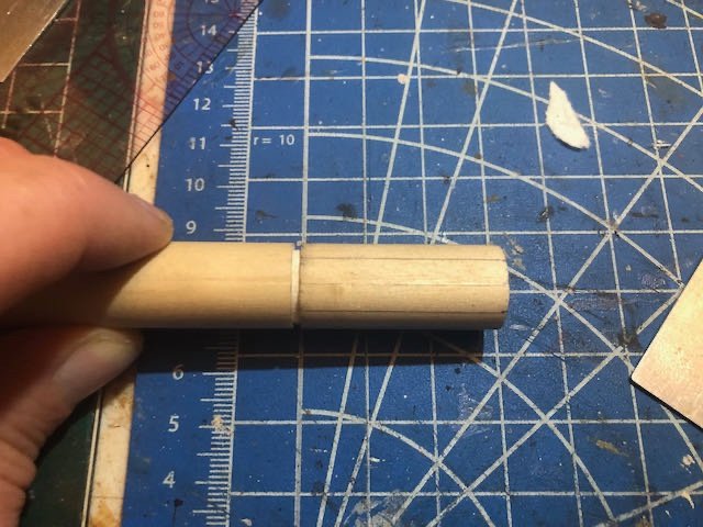
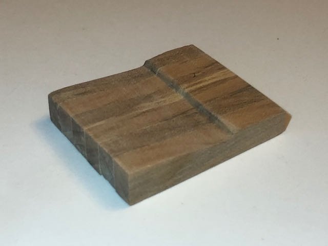
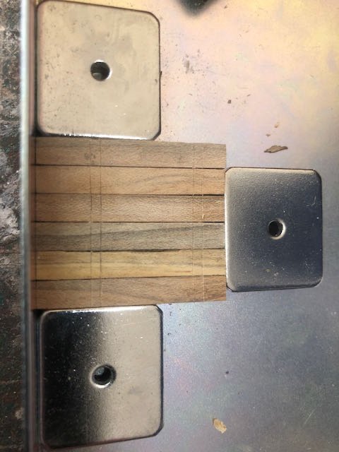
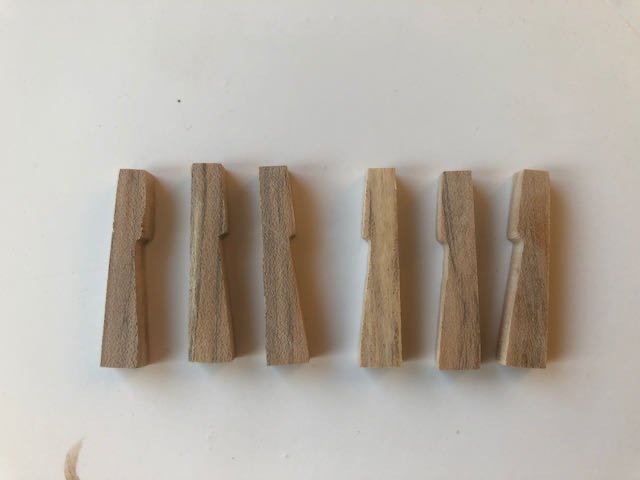
Next up, making the whelps, which turned out to be pretty straightforward even though I thought it would be more difficult because they have such a complex shape. The plans and instructions were clear and easy to follow, though I diverged from them in a few places. Here's what they're supposed to look like (from @tlevine's log): There are five of these, but I cut six blanks to account for making a mistake somewhere along the way. This was the correct decision. The instructions suggest making a paper template and cutting each out separately, but I didn't trust myself to do this consistently enough (especially with hard maple at a small scale), so I spot-glued all six together and did the basic cut on a bandsaw. This violates the "only a small table saw" rule of the Intermediate build, but I had the tool on hand so I used it. The instruction's method would work fine. I used sandpaper and files to finish the basic shaping and get the whole block consistent: Each whelp has two sets of angular grooves carved into either side, to accept some braces. I decided to think ahead and mark these across the block before I separated the whelps. So on the back (which won't be seen), I measured the grooves' locations and scribed them with a knife (one stroke went awry but this side is hidden so it doesn't matter): I soaked the block in alcohol to separate the pieces. Apparently I used too much glue in one joint, because one whelp tore away some wood from the side of another. Instead of soaking myself in alcohol, I gave thanks that I'd started with six instead of the required five. I cleaned up each piece using fine sandpaper, and in a fit of stupidity, sanded the back as well, mostly erasing my carefully scribed consistent marks. Once again I resisted soaking myself in alcohol, and clumped all six together on my magnetic board before rescribing the marks: To cut the grooves, I transferred their location to either side using a knife, then made a top cut using a razor saw: I then used a sharp hobby knife to cut the basic angle into the groove, and finished it with a triangular file. Below, the left-hand groove shows the initial saw cut, and the right-hand one has been carved out: I used my damaged sixth piece as a test case before doing the rest. And here they all are together and separate: You can see that the side grooves aren't perfect, which is entirely due to the limits of my skill set and the small scale of these pieces. Given that these are meant to accept side braces, I think it'll be ok as I can adjust both the grooves and braces as I assemble the whole thing. Also, the plans show the top grooves being ever so slightly smaller than the bottom grooves (1.75" x 0.75" vs. 2" x 1"). I'm not sure why this is, I assume something prototypical, but at 1:24 these differences measure in the hundredths of an inch range, and I just didn't think it was worth being that precise (or that I could rely on myself to be that precise consistently). So I made the grooves essentially equal and will adjust the braces to match. I realized in writing this up that I haven't drilled the bolt holes shown in the plans, but that's a minor detail. The project is back on track and I can see it taking shape. Thanks for reading and sticking with me.

-
I must agree with Michael. While the individual letters are nice, there's a pretty clear unevenness across the word that stands out to the eye, particularly when the rest of the model is so crisp and pristine. Although if his suggestion is to just cut between letters and transfer panels, I wonder if that would produce an uneven surface look that would also stand out? Here's another thought, since we're spitballing. Would it work to print out the actual lettering you want (white on a black background), then cut and transfer the entire piece of paper to the wood using something like diluted wood glue or another fixative? This would eliminate any unevenness from hand-drawing (however careful) but would give a smoother surface and perfect layout. I know you said you didn't want to print because getting the letter sizes right would be difficult, but my suggestion would be to make a number of different sizes laid out on the same page (small adjustments to the font size), print them out as blank ink on white paper to save ink, choose the size that fits best, then redo that one as white lettering on black ink within the overall outline you wanted.
-
Steamboats and other rivercraft - general discussion
Cathead replied to Cathead's topic in Nautical/Naval History
I don't know the presenter, but hope the talk is good!- 281 replies
-
- 2
-
-
- Steamboats
- riverboats
- (and 3 more)
-
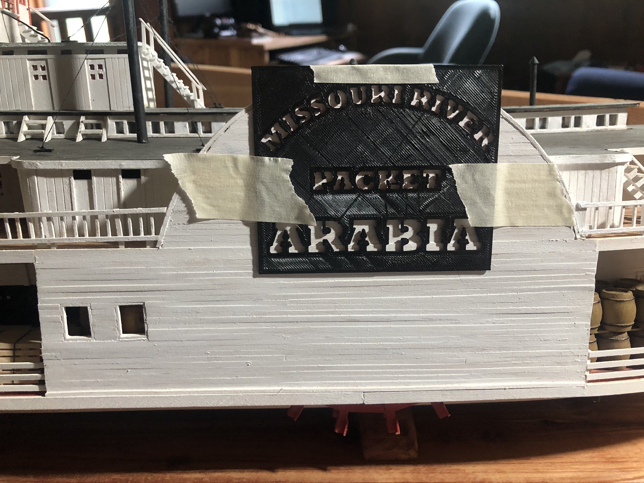
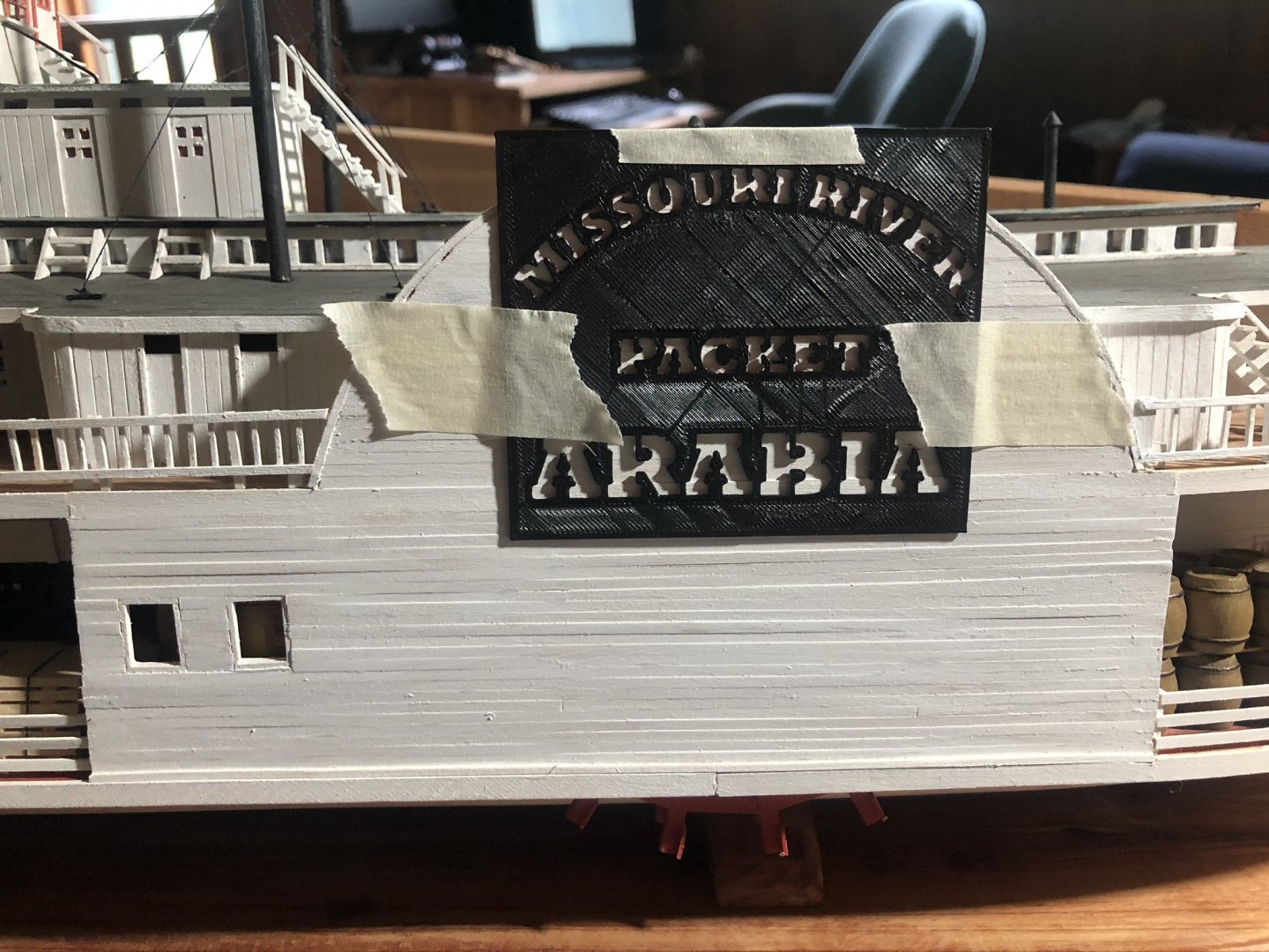
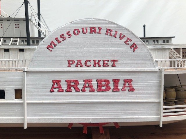
Here's an outside-the-box suggestion on lettering: have you considered getting a lettering stencil/template 3D-printed? On my steamboat Arabia, I designed the lettering I wanted, then paid a friend's teenager to make it on his home-built 3D printer. If you don't have access to such a teenager, there are numerous websites where you can submit a design and they'll make and ship you the print.
-
In your last post, did you mean "transom" rather than "transform"? Not intending to be pedantic, it genuinely confused me and if you did mean the latter, can you explain?
-
Steamboats and other rivercraft - general discussion
Cathead replied to Cathead's topic in Nautical/Naval History
I'm resurrecting this thread to let interested parties know about an online steamboat talk coming up on Tuesday, February 8, at 7:00 pm US Central Time: Steamboat Disasters of the Lower Missouri River. This is hosted by Missouri River Relief, the same organization that hosted my own steamboat talk last March. It's free and open to everyone. MRR does good work in the region and I hope some of you will find the talk interesting.- 281 replies
-
- 4
-
-
- Steamboats
- riverboats
- (and 3 more)
-
Fantastic! Any idea how were those hatch covers held open? Some sort of prop stick from below, or some sort of chain/rope from above?
-
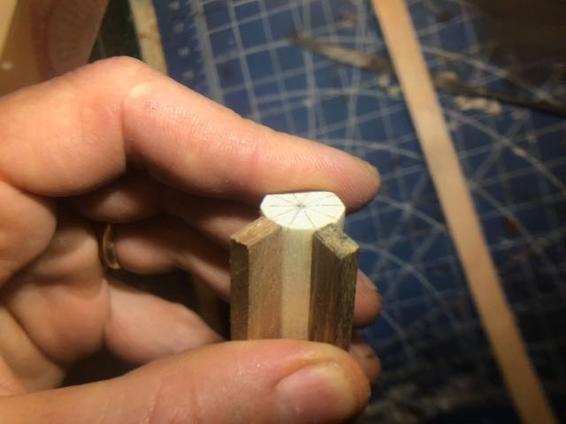
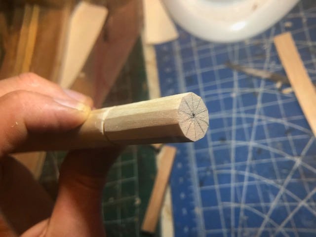
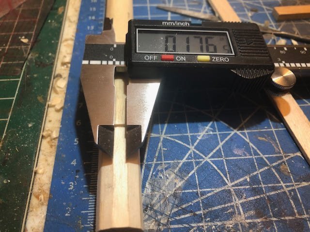
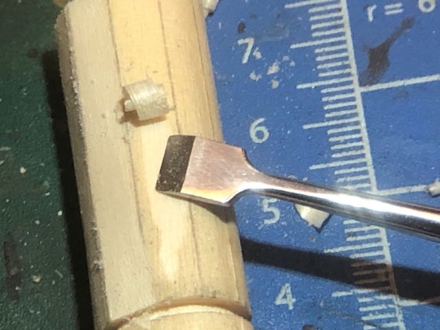
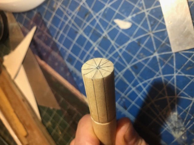
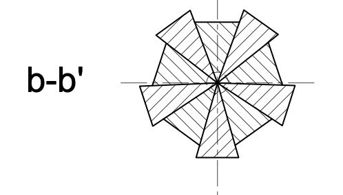
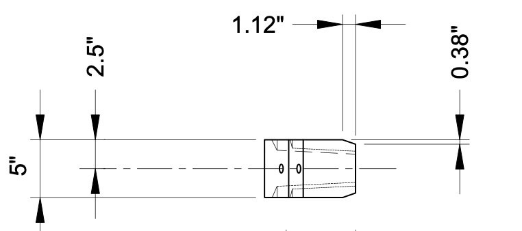
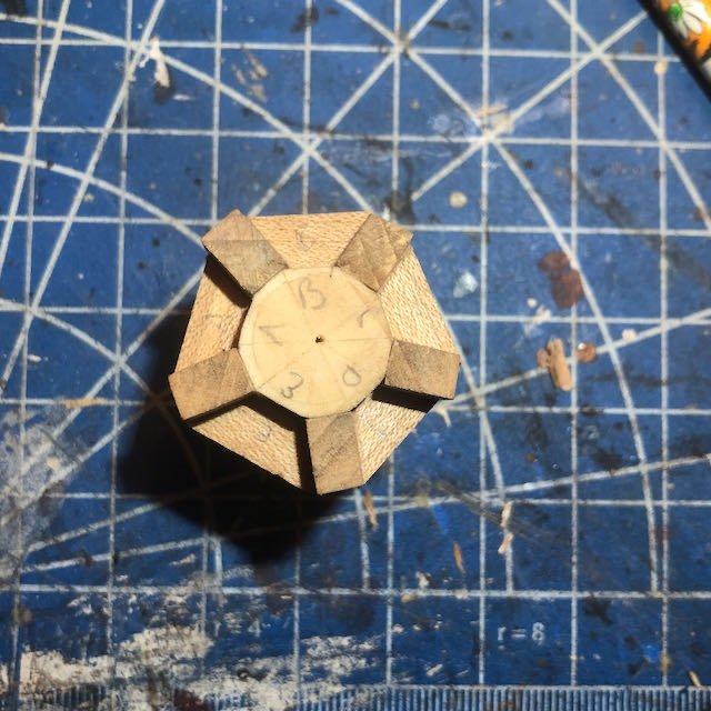
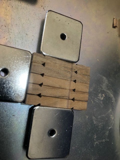
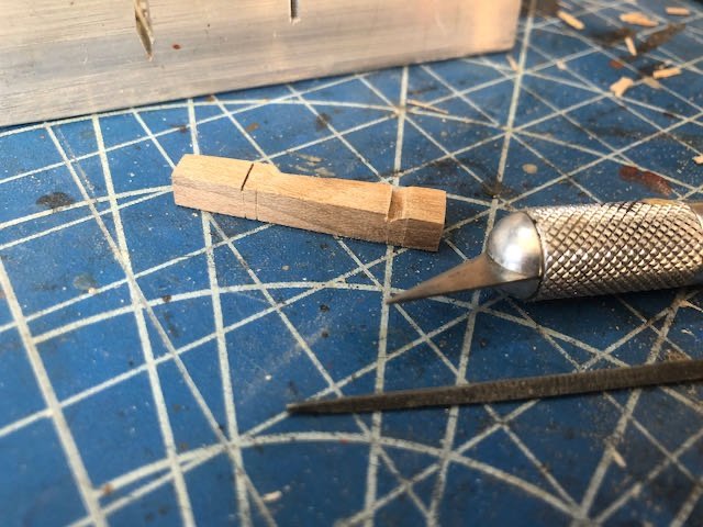
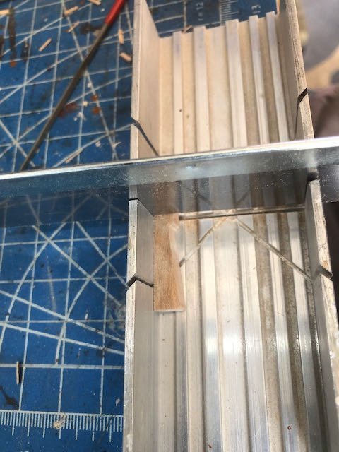
So I took a shot at carving a barrel wedge based on my best interpretation of how to go about it (essentially drawing (c) above). It was very difficult for me, especially at the smaller 1:24 scale, and using hard maple. It was a lot of work slowly chiseling down a consistent angular plane on a narrow piece only ~1.5" long, and the results were inconsistent with the need for a lot more sanding. Doing this nine more times didn't feel very inspiring. So I tried a different approach, based on the Advanced version of this project, in which the entire barrel is shaped from a single piece of wood using a power mill, rather than being assembled from 10 hand-carved blocks. I reasoned that I could probably hand-shape a ten-sided dowel at least as accurately as I could hand-carve 10 narrow wedges and fit them into a consistent circle. The Advanced plans give a barrel diameter of 13" (0.542" at 1:24). This is close to a 5/8" dowel I happened to have on hand (0.625") and I knew I'd need to remove material to get the shape right, bringing the final diameter down. First I carefully marked the center using my caliper, then used a 72º template cut from cardstock to divide the barrel into ten more or less equal wedges. Interestingly, the Advanced and Intermediate plans diverge here; the Advanced plans simply use a consistent 72º angle while the Intermediates call for different angles in the different wedges. The former seems easier to me. I used my Byrnes saw to cut a shallow notch marking the end of the barrel, to avoid tearout as I cut down the sides: I then used a sharp model chisel to flatten each "panel" (representing the outer edge of a wedge), then finished each one with sandpaper and a file, creating a ten-sided barrel (in an ironic reversal of how round masts are shaped from square stock): Now, these aren't supposed to be even like this; five should stand out while five should be recessed; the whelps fit into the recesses while the wide parts extend between them: One solution would be to sand/carve every other panel down to make this recessed pattern, which I think would still be easier than making ten wedges. But here's the crafty part, in which I kill two birds with one stone. The first bird is the need for this recessed/extended surface. The second is that this dowel is not maple and so won't look like the rest of my wood where it's exposed between the whelps. Now, each whelp is 5" wide (0.208"), but with a small bevel on the inner face to fit in between the wedges. Based on the measurements given in the plans, that means the actual whelp face making contact with the wedge is 5" - 0.38" - 0.38" = 4.24" (matching the PN027 wedge faces marked as being 4.25"). This converts to 0.177" at 1:24. I measured my 10 faces and found that they were just right: So this means I can glue accurately-sized whelps right to each alternating face of this dowel. But what about the extended wedge faces between each whelp? I simply plan to make very thin pieces of maple veneer to fit between each whelp after the latter are installed. This will create the illusion of whelps fitting into notches while making all the exposed surfaces maple. I'm feeling pretty good about this solution. Some of it is luck (that a standard 5/8" dowel happens to be so close to the needed diameter at 1:24), but even in other scales I bet a dowel could be scraped down or built up to a ten-sided shape that would work pretty well, especially as most of it is hidden and is really just an internal mounting surface for other pieces. This is the third time that I've found it easier, or at least no harder, to follow the Advanced plans rather than the Intermediate ones even though I'm only using hand tools and a Byrnes saw. The first time was when I found it easier to cut square (rather than angled) mortises for the deck beams and carlings. The second was when I found it fairly easy to make the lap joints for the capstan base rather than simply edge-gluing them (the skills needed for that were far more basic than needed for the rest of the project, so why not make it look nicer?). And the third is now when I found it easier to hand-shape a solid ten-sided capstan barrel (without needing a mill) rather than making a ten-part structure. So going forward I'm going to make a habit of always reviewing both sets of instructions and drawings, looking for the best way to achieve any given step. It wouldn't be modeling without problem-solving!