


Cathead
-
Posts
3,522 -
Joined
-
Last visited
Content Type
Profiles
Forums
Gallery
Events
Everything posted by Cathead
-
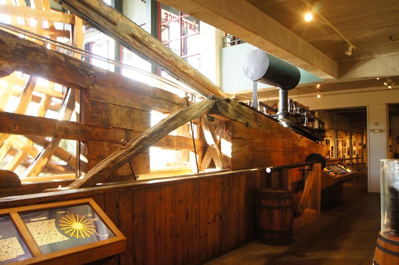
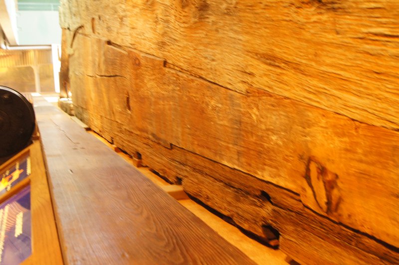
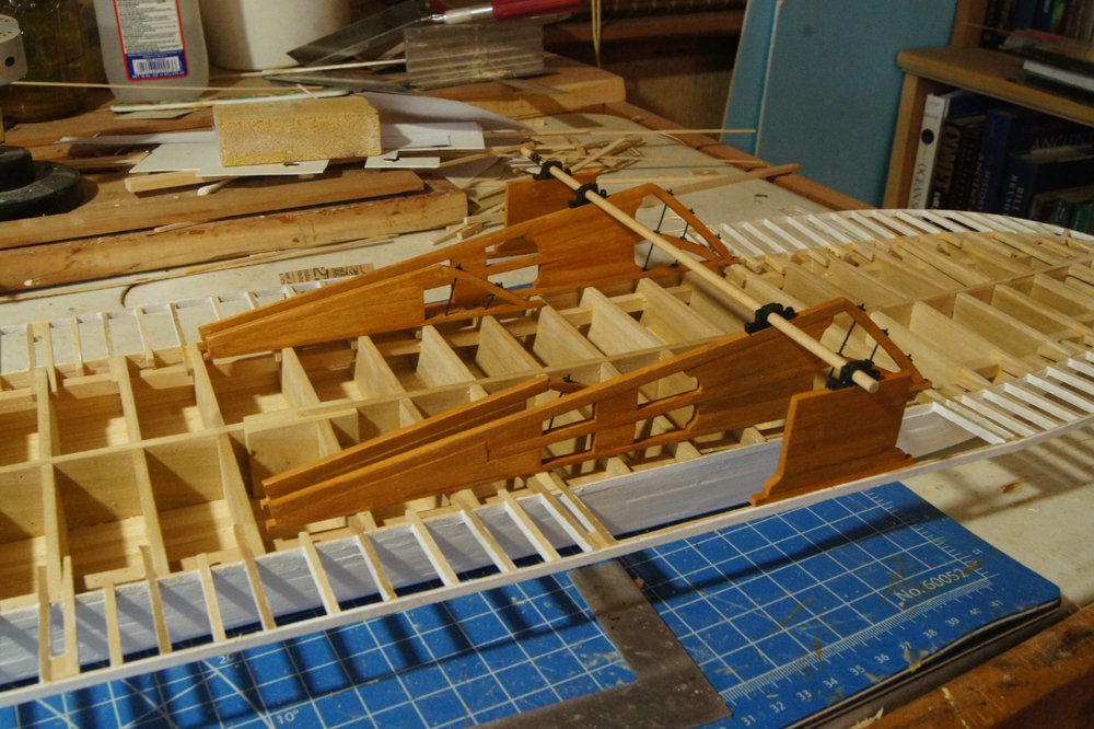
 So those drawings, which you also posted earlier, appear to show that the cylinder timbers are a solid mass of stacked timbers underneath the engines, switching to an open lattice about halfway along (more specifically, two lines of parallel stacked timbers with the engine suspended between). The idea here was likely to provide the maximum support for the weight of the engines and for the vibration and pounding they produce. For example, see the similar arrangement on Arabia here: Those drawings also accurately show how such stacked timbers were mortised into each other for greater strength, as you can see better here: However, one difference between Arabia and your plans is that the former also used stacked timbers to support the weight of the wheels (see below) while your plans show an open lattice below the wheels, which strikes me as a little rickety but I can't say it's wrong. I can't say whether your vessel had the same arrangement below the engines as Arabia, just that it's what the drawings appear to show and that it was a common practice. Don't mean to be critical, I just know you're interested in accuracy and I wanted to ask in case you cared. If you do want to go with this approach, you wouldn't have to tear down what you've done, I bet you could sheath the forward part of your cylinder timbers in thin strips that would nicely simulate solid timbers, especially once the engine room area is mostly enclosed except for the viewing opening. Otherwise it's a clear case of modeler's license and no harm done. Here's a view of my Arabia in progress, which gives a more 3D view of the timber arrangement than the museum photos do (scale has its advantages): You might also contact a few of the true steamboat experts on MSW, like @Roger Pellett or @kurtvd19, who may have deeper insights than I do into engine layout on larger sidewheelers like this. After all, if there's one rule about Western River steamboats, it's that a lot of different designs were experimented with and it's difficult to assign hard rules on "how it was done".
- 238 replies
-
- 5
-

-

-
- Robert E Lee
- steamboat
- (and 3 more)
-
So my stepfather was indeed thrilled and moved by his Christmas half-hull, thanks again to the NRG and @tlevine for developing this. For those who expressed an interest, I just started my NRG capstan build, if you want to follow along.
-
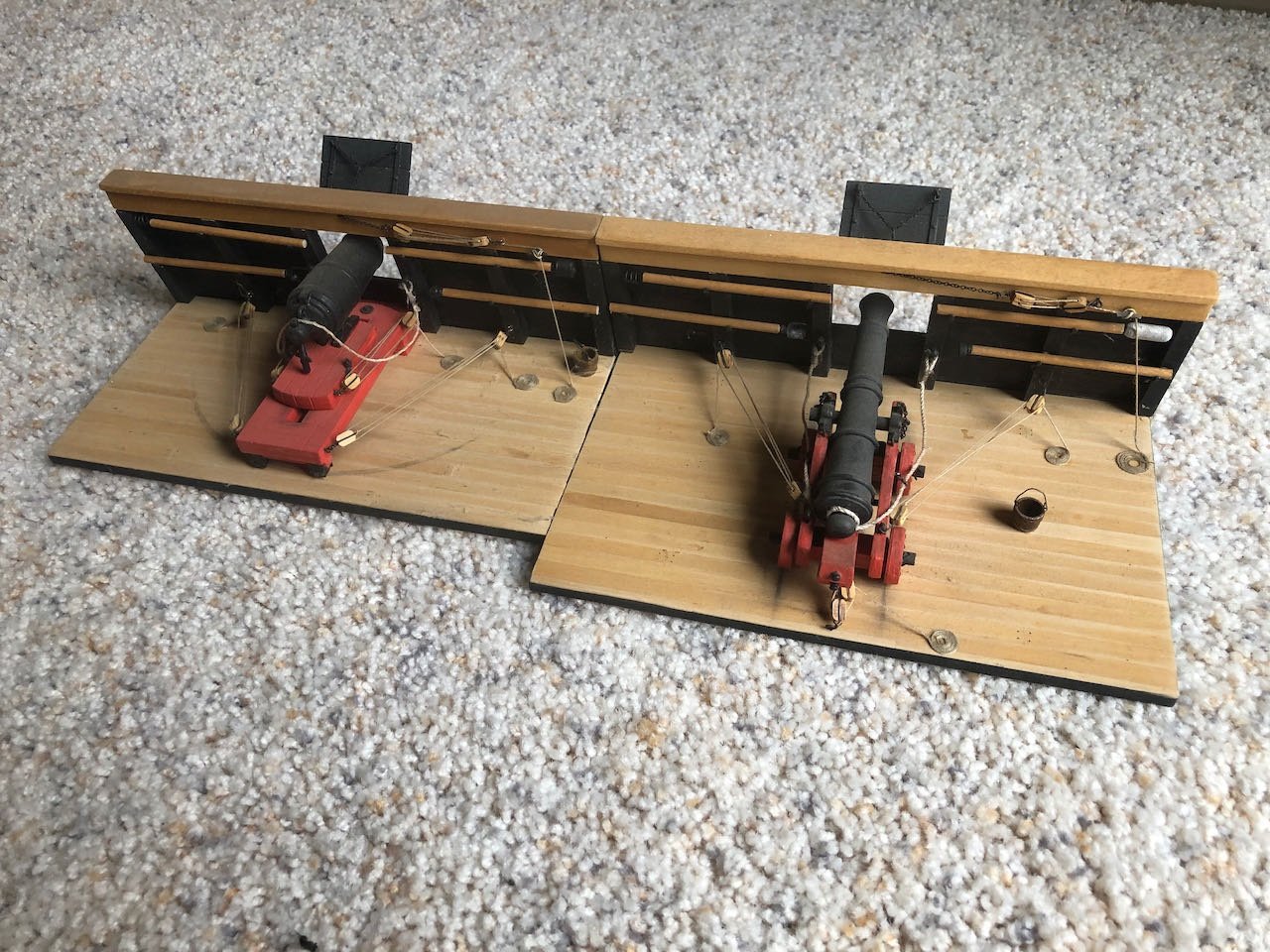
This will be my take on the NRG's capstan project, sold as a set of plans to help modelers learn and practice scratchbuilding skills: The project can be completed in Advanced or Intermediate mode, depending on the level of tools and skills the builder has. There are three build logs for this that I've found; the original by @tlevine, one underway by @gjdale and one completed by @usedtosail. If I've missed any, please let me know! My build will differ from those above in three ways. First, I'll be following the Intermediate instructions whereas the other two are Advanced, so hopefully this will be helpful for others interested in that track. I have a Byrnes table saw but not the higher-end mills and other power equipment needed for Advanced. Second, the assumed scale for the project is 1:16 and the builds above are all in that scale, though the instructions encourage builders to consider other scales as learning to read plans and convert measurements is part of the project's goal. So I'll be converting mine into 1:24 because I want to display it with two 1:24 Model Shipways naval cannon dioramas I've built previously: Third, I'll be milling my own wood from material I've logged, milled, and cured on my homestead here in rural Missouri. I'll be using maple, cherry, and walnut, producing a similar color profile to my recently completed NRG half-hull planking project: Hopefully these differences will make this build unique and useful to others considering this really cool project. Thanks to the NRG, and especially Toni Levine, for putting this together.
- 69 replies
-
- 10
-
-
Good progress so far and I hope you keep updating this.
-
That's a lovely hull. How's the project coming along?
-
I visited the current Niagara just before the pandemic kicked in. Looking forward to seeing your progress on this.
-
Welcome to the forum! I hope you'll keep this updated, I'm curious to see how you go about improvements.
- 8 replies
-
- 1
-
-
- Plastic
- Constitution
- (and 2 more)
-
Nice work! I'm curious about the decision to leave the cylinder timbers (the angled wood supporting the engines) as an open lattice rather than a solid stack of beams as on most prototypes. Aesthetic preference or did you find an example of this approach?
- 238 replies
-
- 1
-
-
- Robert E Lee
- steamboat
- (and 3 more)
-
I love that you're working together on this. My wife and I both trained as geologists and are serious naturalists, so a Beagle is high on my project list. I'm learning a lot from the various builds that are improving on the kit, and looking forward to seeing what you do.
-
Any further progress?
-
It's a nice job for a first build, something you'll be proud to display. Thanks for starting the log and it'll be fun to see how you finish!
- 10 replies
-
- 1
-
-
- Viking Longboat
- Artesania Latina
- (and 1 more)
-
A question occurs to me regarding that anchor storage arrangement: did they have to take down the lines running through the stanchions every time they deployed or stored the anchor? Otherwise it doesn't look possible to thread the anchor in there.
-
Just stumbled across your log, though I've been following Hakezou's for a while now. Like many others, the Shackleton story has long fascinated me and seeing a decent kit of the Endurance is inspiring. Great work so far and another good tutorial in how to improve the kit.
-
Gotta be careful with your wording on a nautical website; for a second I thought you had a local dealer in Chinese sailing vessels. Model looks fantastic. I've definitely considered the aquarium case idea before, seems reasonable. Can't wait to see the final version. As for the rope fuzziness, when I submitted my Viking ship to the NRG contest, one of the judges at first criticized the fuzziness of my lines, then backtracked to wonder whether it was intentional and/or accurate for the rough hand-made ropes of the period. So that can always be your excuse, too!
-
Glad to hear you like it! I was reminded of a bit of advice after using mine last night: the cutter can handle some relatively thick stock, but as you go thicker it gets easier for the blade/arm to deflect and produce a non-square end. It isn't like a miter box where the cutting blade is locked in place. So just be aware of that, at times I've needed to square off cut ends with a file or other tool. Other times I've used the cutter to mark a precise cut and then finished it with a miter saw to be sure the cut was square. Also, change the blades as soon as you feel it's not cutting right. One of the great things about this tool is it's designed to use basic razor blades, not some custom design, so it's easy and cheap to keep sharp. Happy Holidays to you as well, I look forward to this project coming back on the table, so to speak.
-
Just don't forget that on many sternwheelers, the heads overhung the wheels for obvious reasons of disposal! So maybe check the wind direction first (not that that means much on winding North American rivers).
- 109 replies
-
- 2
-

-
-
- Finished
- Artesania Latina
- (and 1 more)
-
So that makes sense, but is that the case for something like the image below, which you shared earlier? It just stretches my logical/factual brain to see those right-hand shrouds as being intended to represent the port-starboard mirror image of the correct ones aft of the mast, since they're carefully placed at a completely wrong angle symmetrical to the right ones. In addition, the three forward shrouds are even drawn as combining with what appears to be a forestay before reaching the mast, different from the aft three (oddly, there's no aft stay at all). I realize these aren't blueprints and that art in this period was somewhat abstract, but it boggles and fascinates me to try to understand the mix of detailed realism and perspective inaccuracy. It's like trying to learn a truly foreign language with some recognizable patterns but fundamentally different grammar (like Japanese numbers). ] Not trying to take this thread too off course, I'm just fascinated, and part of the theme here is understanding what we can learn and understand from these images.
-
Some of those images seem to show shrouds both fore and aft of the mast, while your prototype shows them only aft. Thoughts as to why?
-
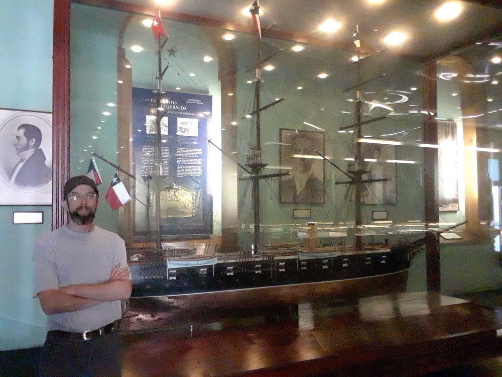
To me, one of the significant tradeoffs is how to handle details at scale. The larger you build, the easier it is to get details in scale, but you're also under more pressure to include those details and get them right. The smaller you build, the harder it is to get details in scale, but you can also start eliminating them. Examples in wooden ships could include treenailing, rope thickness, wood joinery, sail stitching, and even just the texture and grain of the wood itself. As for examples of large-scale ship models, here I am a few years ago with a 1:20 model of the Esmerelda at the Museo Maritimo Nacional in Valparaiso, Chile.
-
Not as such, given the damage to the wreck, and the museum just displays one full engine/wheel assembly out of context. But in the thread I linked above are several photos of the wreck that show the boilers and engines in place, which give a sense of the overall setting. Details are gone, washed away by the river, but from various things I've read the area might have included a small blacksmith's shop and other workbenches (boats generally had to do their own repairs, even on the relatively civilized Mississippi River).
- 238 replies
-
- 1
-
-
- Robert E Lee
- steamboat
- (and 3 more)
-
Great find of the engine drawings! That'll be a challenging but fun project. In case you hadn't run across it, when I was planning my Arabia build, I made a separate thread to share the various photos I'd taken at the museum and found in my research; these include a lot of views of the engines and wheels, both at the museum and from the original excavation. You might find it useful to look through that for real-world views of the actual machinery, which does look very similar to the plans you show above. I can also look for additional photos in my collection if you're trying to see a certain viewpoint not shared in that thread. Regardless, can't wait to see how you approach this.
- 238 replies
-
- 2
-
-
- Robert E Lee
- steamboat
- (and 3 more)
-
Keith's suggestion is good, you can set up a pretty simply jig using a clamp and a piece of wood as a stopper at the right length; just butt the piece to be cut against the stopper and you'll know that the saw is working in the right place. As another option, I strongly recommend the Northwest Short Line chopper: It's excellent at making accurate, consistent-length cuts at various angles. I even use it for pieces that are too thick for it to cut on its own, by using the blade to mark each piece accurately. The divot made by the razor blade becomes a natural guide for a razor saw. But if I'm right about the scale of the pieces you're showing, the Chopper would make short and accurate work of them, one after another. I'm not a big tool collector overall, but this one is simple, affordable, and fantastically useful for all sorts of modeling applications, which inevitable require that you cut small parts to consistent lengths (or angles).