amateur
-
Posts
3,533 -
Joined
-
Last visited
Content Type
Profiles
Forums
Gallery
Events
Everything posted by amateur
-
Thanks: the version my shop sells is labelled 'heavy', so I think I can deduce which is which Jan
-
With respect to the EZ-line: Do you use the thin (0.25mm) or the "thick" (0.5 mm) version? Jan
- 98 replies
-
- 10
-

-
Or he needs starting a very large, very complicated model with lots of tiny parts, so that he is busy at least three weeks. Having said that: actually I like these slightly less complicated models more than the very complicated ones: they have the looks and feel of a good model, and they are not afraid of showing that they are made of paper. Jan
- 98 replies
-
- 10
-
-
We all got that time-out message. As usual: the mods told us what was going on as soon as they were aware of the problem. As soon as the site is down, the facebook-page of MSW is their way of communicating with us. Jan
-
Blinking with my eyes, and you’re half done already. looking good Jan
-
Sometimes I wonder why there are not more model kits of these type of ships. They are so beautiful. Apparently kit makers (and buyers) prefer another victory over a cruiser like this. (I know, there is quite a lot out there in the plastic/resin-world, but that is way outside my skillset, as is scratch building one of these beauties) Jan
-
DEVICE TO FINISH ROPE ENDS TO HANG ON BITTS AND BELAY PINS
amateur replied to Peter6172's topic in Masting, rigging and sails
Somewhere in Edt's log of young america there is a jig for that last method. Couldn't find it, but also works very well. Jan -
Surely there are some polish speaking people around here? Jan
-
Make a copy, and try before you cut the real thing? Jan
-
Help with masthead and topsail pole
amateur replied to modeller_masa's topic in Masting, rigging and sails
Got it. I checked pastors again, but there is no indication of a fixation at the lower end of the pole. (Also not in the other pictures) My guess is as good as yours.... Jan -
Help with masthead and topsail pole
amateur replied to modeller_masa's topic in Masting, rigging and sails
The AL-picture shows something that I think is in line with Pastors book: a fixed pole, secured to the lower mast. I think you get a very realistic looking model when you take Javier Pastors books (page 86 shows the shrouds) Given the small amount of sail that should do. Also, as there is almost no sail to that mast, there is/was no need to have shroulds on that top-mast. (according to Pastros reconstruction, but also according to others). Jan -
Took me some time to find the gallery on my mobile Getting old as well.... Jan
- 7 replies
-
- 1
-
-
- photo gallery
- photos
- (and 1 more)
-
Which is not there when using the mobile-layout, or at least not as obvious as this) In mobile-mode, it is only available in the menu (upper right corner) Jan
- 7 replies
-
- 3
-
-
- photo gallery
- photos
- (and 1 more)
-
Impressive! I know it is part of the fun, but it is a shame that alll thise frames and deck structures are disappearing behind the outer skin Jan
- 201 replies
-
- 7
-
-
- SD 14
- Marcle Models
- (and 1 more)
-
The military museum n Soesterberg still has one in the collection. (The emblem in colour) Rather noisy things, those f15s, flying low above the surrounding villages (and never alone. Teacher had to stop talking when they were flying over, and the windows were trembling ... ) Jan
-
I think much more, about 40-50 centimeters? Jan
-
Maritiemdigitaal is next to useless. Even if you succeed in finding what you are looking for the quality of both picture and description is almost always insufficient. Jan
-
Not only the printing is clever. The glueing trick also deserves to be remembered Jan
-
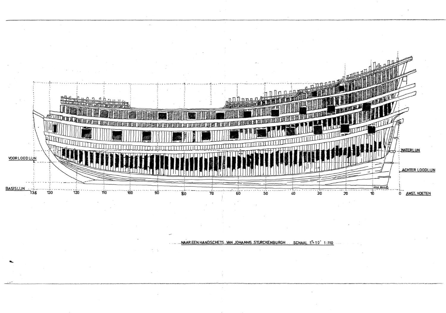
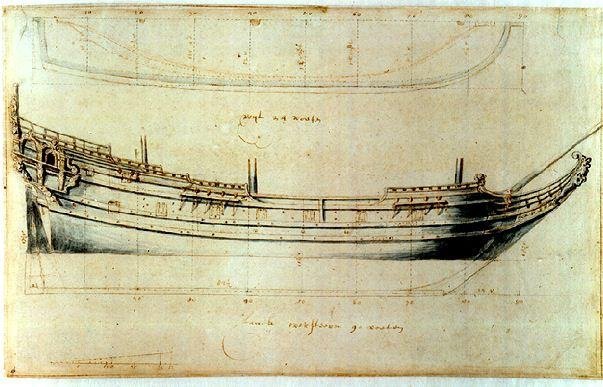
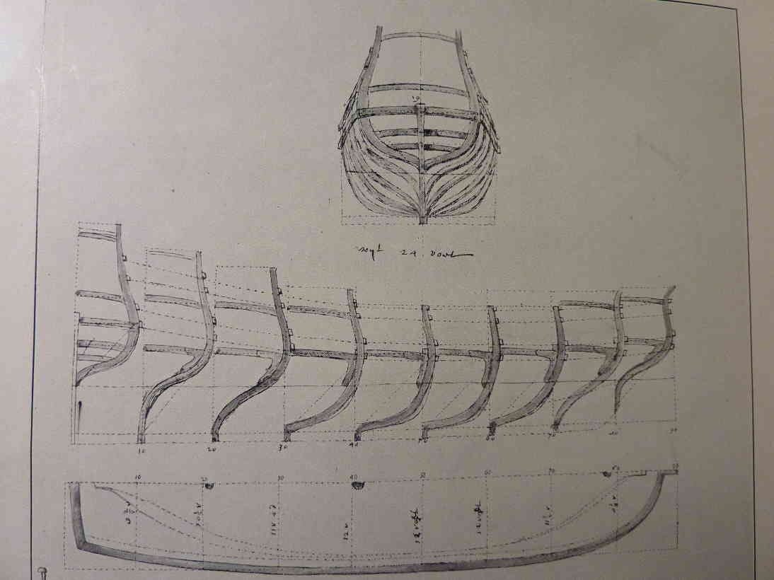
Side view and waterlines of a small frigate Section drawn by Sturckenburg (I could only find the redrawn version of Otte Blom) Could only find a book-copy of the third drawing I never heard of any other drawings at the Maritime miseum, nor did I see any pictures of such drawings. Would be very interesting to know whether there exist any other drawings. Jan

-
Hi Philemon, what surprises me is that in all the builders-contracts there seems to be no reference to any drawings, nor to the approval of such drawings before the work commences. One of the members here (Werner) has spent literaly weeks in the Dutch archives and nowhere seems to be anything that points at such drawings or the use of them. Only from almost a century later (Pieter Zwijdrecht), there seems to be a number of linedrawings that were used in shipdesign (and I assume, also the building of those ships). Any thoughts on that? The drawings in the scheepvaartmuseum are three drawings that are available in the web: a longitudinal section of a threedecked ship, attributed to Sturckenburg, and two technical looking drawings of a smallfrigate (most Berlin-reconsteuctions are based on those drawings). A coupke of years ago Ab Hoving published a review of these drawings, suggesting a more in depth research of these drawings: He notices some problems with the drawings. They are made on paper that has a watermark that is (or seems) newer than the date on the drawing, there are technical terms in the drawings that do not match the terminology in the builders contracts, the construction/frames do not match what we know of building practice in that period, They have no provenance and they came in possession of the museum in a period that there was a huge demand for 'stuff from the golden age'. I will look for a web-link. Jan
-
60 dollars seems to be the lowest shipping costs I can get Makes buying rather expensive …. Perhaps a problem for all packages from there to here, but in this way american webshops are not avserious option for european buyers Jan
-
Yrah,, and it is self-classified as ‘good enough, but not perfect’. Makes me wonder: How would a ‘very good, near perfect’ look like?? I only know paint by brush, those airbrush-jobs look terrific. But I guess it takes more thsn you can see (in talent, time and experience) to get it ‘not perfect’ like this… Jan
-
Off and running with the schooner rigged pond yacht
amateur replied to Elmina's topic in Masting, rigging and sails
The pic you showed of the original rigging (or at least, the remainders of it) do not show any signs of ratlines on the aft mast. I would leave them out, without ratlines, she has a cleaner look. Jan -
Mis-identifacation or not. I would call it a pretty close match to the original
- 23 replies
-
- 3
-
-
- card
- World of Paperships
- (and 2 more)