kurtvd19
-
Posts
3,021 -
Joined
-
Last visited
Content Type
Profiles
Forums
Gallery
Events
Everything posted by kurtvd19
-

Simple Drying Rack
kurtvd19 replied to hornet's topic in Painting, finishing and weathering products and techniques
This is a great idea and I will be making up a very similar drying fixture. Thanks for the idea. Kurt -
Tracing light-box
kurtvd19 replied to Jason Builder's topic in Modeling tools and Workshop Equipment
I got an X-Ray light box from a vet and have used it many times as well as loaned it out to fellow club members. With the move to digital x-ray viewing there are lots of excess light boxes out there. Ask you vet or Dr. I have even seen them at garage sales and some time ago saw one at the Goodwill store. Their lighting is very even. If you make one from plate glass like the one initially shown in this thread you can stretch a translucent panel across the supports below the glass to even the light out. A fluorescent light panel works as does a white shower curtain type of material - which also works as a diffuser for photographic lights. Kurt -
Household Ammonia
kurtvd19 replied to Q A's Revenge's topic in Building, Framing, Planking and plating a ships hull and deck
The bit below was originally posted last year. Kurt Posted 10 October 2014 - 09:12 AM I have never used ammonia to bend wood - it just isn't needed. The bit below is a reprint of part of my article on building the Gunboat Philadelphia kit in Ships in Scale. I doubt anybody who attended the NRG Conference I reference has ever used ammonia since hearing it. Kurt AVOID AMMONIA SOAKING At the 2007 Nautical Research Guild Conference in Manitowoc, Wisconsin Alex C. Wiendenhoeft of the U S Department of Agriculture Forest Services Center for Wood Anatomy Research at the Forest Products Laboratory in Madison, Wisconsin explained how and why this damages the wood. After this length of time I do not remember all of the details of his talk, but the point was well made and I don’t think that any of the modelers who listened to his talk that day has ever used Ammonia again. The very non-scientific points I remember is that soaking in Ammonia breaks down and liquefies the Lignin in the cells making the wood more bendable. When the Ammonia evaporates while the wood is clamped in place to the desired bend, the Lignin solidifies in a somewhat degrade state weakening the wood. Ammonia also causes some woods to discolor when they dry out. This might not be critical when the wood is to be painted but if it is being stained or clear finished the discoloration would not be acceptable. Concentrated Ammonia fumes are used commercially to darken some woods with oak being very susceptible to this process. Mr. Wiendenhoeft explained how and why soaking in water or steaming wood made it bendable while not damaging the cellular structure of the wood. Again, a non-scientific explanation is that there is a chemical bond with water in the cellular structure of wood that varies between 0% and 30%. Soaking or steaming wood with water raises the percentage of water within the wood, called “free water”, above the amount bonded within the cells temporarily. This makes the wood swell and more easily bent. When the wood dries out and the bonded water stabilizes back to 30% or less, the wood retains the shape it was formed to by the clamping while it dried while retaining its strength. I have only mentioned drying the wood while clamped in place but the application of heat using some sort of plank bending tool or other heat source works the same way as clamping just at an accelerated rate. -
Meet Your NRG Directors and Officers
kurtvd19 replied to tlevine's topic in NAUTICAL RESEARCH GUILD - News & Information
Chuck - next week. That's a threat !!! Just so busy I fell way behind. Kurt -
The Archer "rivets" are minute bits of C/A on decal film. The strip of rivets is cut from the sheet and applied like any decal. The film is very thin and a bit of clear coat blends the edges into the surface so the edges of the strip are completely invisible. I have done the hand applied drops of C/A and the Archer rivet decals - will never do the hand application again. They also have weld seam decals that work the same way. Depending on the scale you are working in would determine the scale of the rivets or welds you applied. Ho or the larger 1/48 scale decals might both work on the same model depending on the size of the rivet being replicated. Kurt
-
I usually leave the commentary on the Journal articles to others, but I have gone beyond my inspection of the proof copy of this issue. I have been reading a couple of the articles off my computer screen because I couldn't wait for the printed copy. This is unusual activity for me - I hate reading off the screen (but not so much since I got the big 27" screen). I think the cover photo is fabulous as are the photos that accompany the article. I think a lot of members will be very interested in the author's thoughts on the subject of updating dockyard-style modeling. We should go to press Monday. Kurt
-
Blackening brass problem
kurtvd19 replied to Maury S's topic in Metal Work, Soldering and Metal Fittings
I too am a proponent of Birchwood Casey Brass Black. Pickling in vinegar for an hour is OK I guess. I use warm Sparex for that for 10 minutes or so and then a rinse in water. If you do a rinse in acetone you only need to do so for a few seconds - longer isn't doing anything except wasting time. Dip the clean brass part in the Brass Black for just a few seconds using tweezers - keep the part moving gently while immersed and then lift out with the tweezers, and let the solution drip back into the container. Dip again and let it drip while watching for the degree of black you want. Don't soak for extended times it will build up a crust that will flake off. Rinse well in water and let dry - don't handle the part. If it's not dark enough repeat the process in the Brass Black - no need to reclean or soak in etch if you don't handle with your bare fingers. I don't dilute the Brass Black (always did so with Blacken It but I will not use it for brass again) and can't advise one way or the other on doing so but even diluted I would not leave the part in it for any length of time. Hold the part with tweezers and agitate the solution by moving the part gently in the solution and you will get good blackening. Kurt -
I have a drafting chair that has a good back and a pneumatic up and down control that is real good for changing your work height and this helps with keeping me comfortable at whatever I am working on. Lower it and I am at eye level with the deadeyes and raise it all the way up and I can work on the tops. Regardless of your bench height you can be comfortable. Most stationary stores carry these chairs. Kurt
-
Is there a better #11 blade handle
kurtvd19 replied to roach101761's topic in Modeling tools and Workshop Equipment
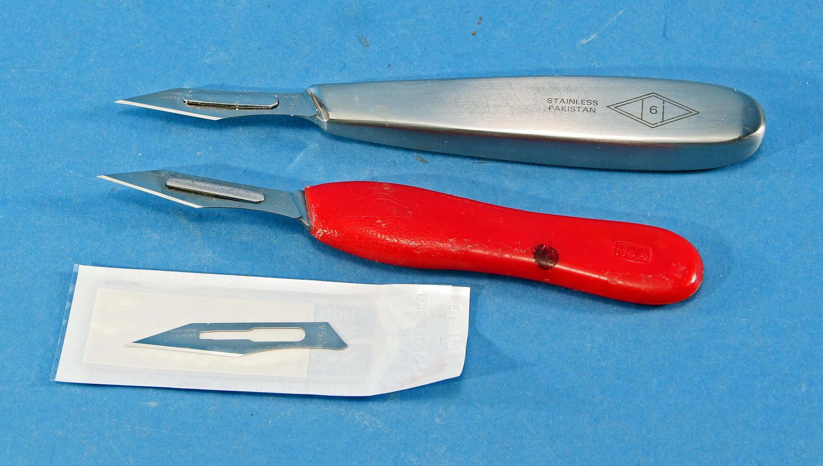
Phil: I have switched over to scalpel handles and blades.. The metal handle is much preferred over the plastic handle but the guy who recommended I switch swears by the plastic handles. Ebay has these for less than $10 each and you can also get the blades on ebay. The blades shown are Swann-Morton #25a. A #11 surgical blade is nothing like the X-Acto #11's. The jeweler's tool category will be your best category to search on ebay. Also, somebody said to use pliers to change the blades. Heed that advice. Do not try it with any fingers you want to use for several weeks. No need for sterilized blades unless you try to change blades using your fingers. Kurt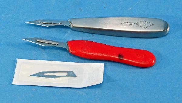
-
Picket boat No.1 problem with first few steps
kurtvd19 replied to paulv's topic in Wood ship model kits
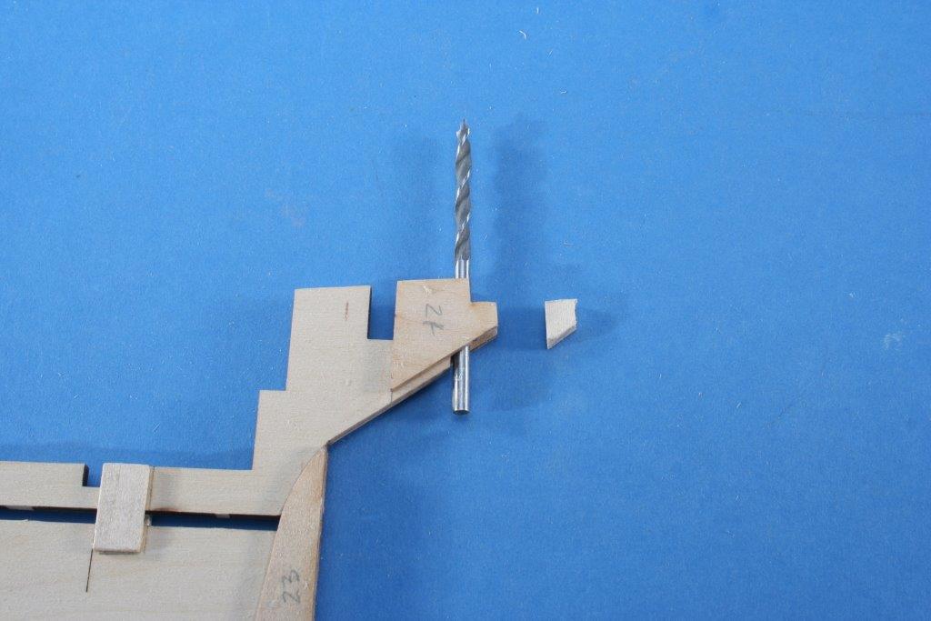
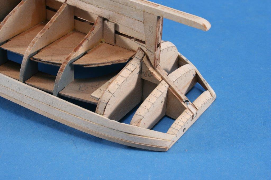
Paul: Align it with the top edge as shown in the attached photo of the piece on the keel. The other photo shows later construction - the lower surface is not important and the keel gets shaped to allow planks to lie flat over the keel. Kurt

-
Has anyone got or used headband magnifiers?
kurtvd19 replied to vossy's topic in Modeling tools and Workshop Equipment
I have used a similar type - Optivisor. The one had been using for years just wasn't cutting it any more and at a trade show I tried their glass lenses - this made a bid difference. Check the Optivisor brand with the glass lenses. They are a bit pricier but they are so much better - 8 hours w/o eyestrain. The Optivisor plus good bright light makes a world of difference. A big help for aging eyes. Kurt -
Richard: I posted the link to Book Collector below. I have used it for several years - only on the home computer (I use my phone as a phone) and highly recommend it. Try the free trial version it handles up to 100 books for free - I think for an unlimited time. When you decide to buy it to handle your entire library (who has less than 100 books?!) there is no problem with updating - it is all seamless. A feature I really like is the ability to show the cover of the book in your listings. When you enter the ISBN number for the book the download if the book information is automatic and then you can add all your personal info about it - autographed, where you purchased it, the amount you paid and the software adds currenet value, the photo of the cover and the publisher and author info. If the cover isn't available you can scan it and enter it and if you click a single box the cover scan will be uploaded to the cloud and the next person entering that book into their data gets your photo downloaded. http://www.collectorz.com/book/ Kurt
-
Steve: I started to use Blacken It but had very poor results. I got a bad batch of Blacken It - I have used it many times and while I use Birchwood Casey Brass Black for brass because I like it better than Blacken it for brass, the Birchwood Casey stuff doesn't work for pewter. So, I ordered some Blacken It and when it arrived I used it on the guns - with nothing to show for the waster $, time and effort. Must have been old or frozen at some point or something because it did not work - period. As I had a magazine deadline to meet, the airbrush was used. I like the results using the airbrush and have shown the guns at club meetings and guys asked what I used to blacken the guns. They couldn't tell the difference - the Badger paints use very finely ground pigments and cover well with a very thin covering. Kurt
- 308 replies
-
- 1
-

-
- finished
- model shipways
- (and 1 more)
-
Check the Revell plastic kits of tugs and other ships. There are some research vessels and other commercial ships available. Kurt
-
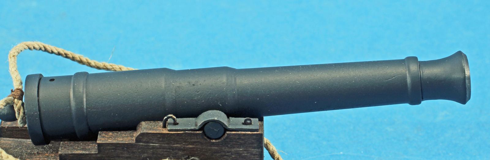
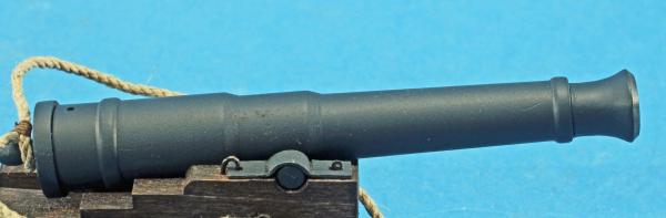
Floquil paints have been discontinued by Testor's - the owner of Floquil. There may be some floating around on eBay or a hobby shop shelf but I seriously doubt that Engine Black would be one of the colors still not gobbled up. I know one modeler who's bought 27 or so bottles of a specific Floquil clear finish - off eBay. The attached photo is the 12 pound gun painted with Badger Modelflex Marine Color Wrought Iron Black (#16-413) an acrylic paint. It is the same color as Badger's Dirty Engine Black (#16-05). This is a somewhat weathered Engine and/or Hull Black which are both dead flat black and look way too stark on guns. Kurt
- 308 replies
-
- 5
-
-
- finished
- model shipways
- (and 1 more)
-
Try the chisel and knife - on some scrap first - the chisel and knife are easily controlled and will be needed constantly through your modeling and while power tools are great and I use them a lot, the Dremel can be a very aggressive cutter and can get away from you and can ruin a piece of work very fast. Try both methods on scrap and then go with the one that works best for you. Kurt
-
Paint brush verses air brush
kurtvd19 replied to medic's topic in Painting, finishing and weathering products and techniques
It's an airbrush for me for 90 percent of my painting. I use acrylics and airbrush cleanup is easy. The secret to airbrushing small areas is to use an airbrush meant for detail work vs one meant for larger areas. Spray cans are of limited use in my opinion with the hobby brands, Testors, etc. being OK but the use of hardware store paints (spray or cans) is to be avoided due to the size of the paint pigments. Model paints are in the 1 micron range while hardware store paints, meant to cover in one application range about 17 to 32 microns and will obscure details.. To avoid water based paints from raising the grain of basswood or other woods a coat of shellac sprayed or brushed will seal the wood and the water based paint applied over the shellac will not raise the grain. Kurt -
Top notch video like all of Paul's stuff. Kurt
-
Can i live without a BYRNES TABLE SAW
kurtvd19 replied to shihawk's topic in Modeling tools and Workshop Equipment
I have the extended fence option and use it most of the time. I got my saw long ago before the tilt away fence was std. so I retrofitted it by getting the new ***'y from Jim and returning the original. Anybody with an older version should get this upgrade - in my opinion. I have the tilting table and have actually used it very little. However, it was a life saver when I had to cut a bunch of 1/2 x 3/32 strips with 45 degree bevels on the long edges for a set of barge covers for a 1/72 model barge for a legal job on a tight schedule and the tilt table paid for itself on the time saved vs sanding accurate angles on about 6 ft of strip wood. The tilt table is a bit awkward to use unless you cut some wedges to match the angle you are cutting and put these wedges under the saw base making the table level with the bench top - in effect, tilting the saw (this tip came from Jim). Kurt -
Miniture machine screw sizes
kurtvd19 replied to grsjax's topic in Metal Work, Soldering and Metal Fittings
I have been working with some 0.5mm machine screws and nuts for shackles on a 1/12 scale sailboat model. I absolutely need magnification to even see them and threading a .5mm nut onto the machine screw is a real challenge. I wonder what the floor in the shop looks like where these things are made. I bought double the number I need in anticipation of several disappearing when dropped - even with my jewelers style pull out bench extension I know I will wind up dropping some. The source I use is Scale Hardware http://www.scalehardware.com/miniature-hex-bolts-c-1 If you are looking for slightly larger stuff such as 00-90 sizes then PSME - Precision Scale Model Engineering http://www.psmescale.com/ has nice stuff for a lot less. The catalog is expensive but the owner will take phone calls and tell you prices, etc. Just got some 00.90 screws and nuts from him - very good service from both of these places. Merry Christmas, Kurt -
David: The reviews on this plane are mixed from great to junk. It's nice and small and if you can get it good and sharp - this will depend on the actual quality of the blade (see the reviews below) as I know you can do the sharpening bit just fine it will probably fit your needs quite well. Kurt http://www.sawmillcreek.org/showthread.php?157725-stanley-102-103-a-good-purchase http://www.supertool.com/StanleyBG/stan12.htm http://stanleynumber103blockplane.wordpress.com/tag/stanley-block-plane/ http://lumberjocks.com/topics/22164
-
Let's talk 3D printers.
kurtvd19 replied to Keith_W's topic in Modeling tools and Workshop Equipment
The replication of carvings is a perfect application for 3D printing. The curvature of the underlying surfaces can be accommodated in the design and the parts can be attached without the not always successful bending of white metal castings (in the case of kits) which are generally quite crude. And for scratch building it will be great for those without carving skills. Many with the skill to build a scratch model shy away from doing so because of their lack of carving skills. Kurt -
Let's talk 3D printers.
kurtvd19 replied to Keith_W's topic in Modeling tools and Workshop Equipment
Joe: The last several meetings of the Association of Professional Model Makers have had presentations and discussions as well as hands on working with 3D printing and some other forms of rapid prototyping from the POV of those destined to be out of work if they don't get with the times. The handwriting is on the wall. Kurt -
Let's talk 3D printers.
kurtvd19 replied to Keith_W's topic in Modeling tools and Workshop Equipment
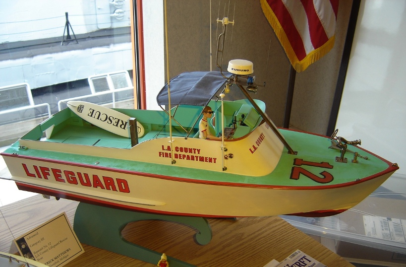
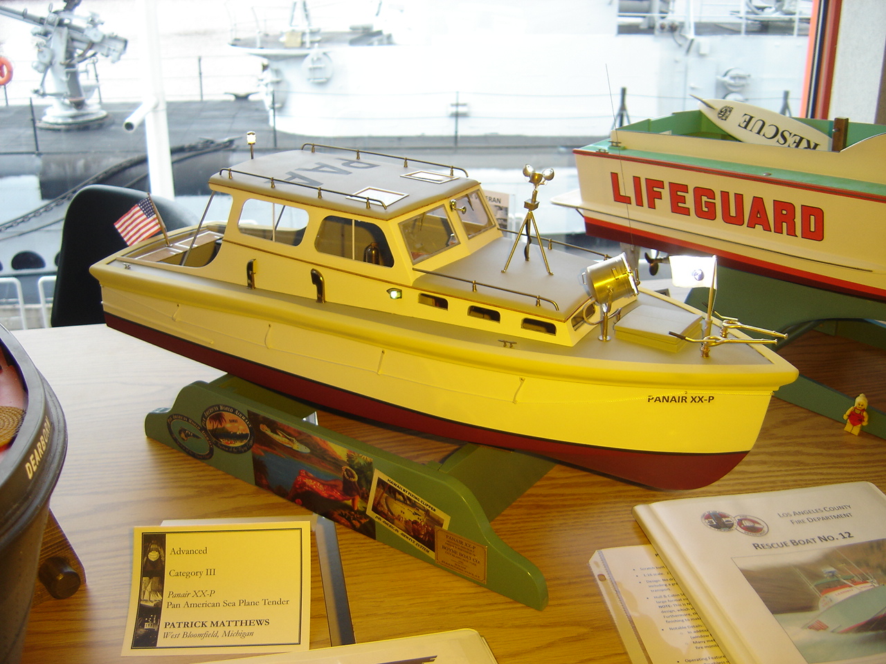
3D printing and rapid prototyping is taking a toll on the traditional commercial model shops that industry uses to make prototypes for testing and for executives to touch and feel. Two club members have recently had big down-turns in their commercial model shop business due to so many businesses now using rapid prototyping/3D printing to make samples for evaluations. There will always be work for these guys as the 3D printers just can't make an 8 foot diameter frying pan, a 12 foot Iguana emerging from its egg or a 6 foot tall egg for a housewares show or large architectural models though a lot of the auxiliary stuff for these large models is able to be done cheaper than by the model maker now using the new technologies. We already had a model with a lot of 3D printed parts (first photo) as well as one with almost the entire model done in 3D printing (second photo) take awards at the WI Maritime Museum's 2014 Show/Contest. Both models are by Pat Matthews. Like photo etch parts qualify as scratch built materials if the builder does the art/design work and a commercial printer supplies the photo etched metal the 3D pieces designed by the builder qualified the 3D parts as scratch built so both models took awards as scratch built models. Kurt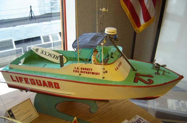

-
Let's talk 3D printers.
kurtvd19 replied to Keith_W's topic in Modeling tools and Workshop Equipment
Keith: I will check into making this article available for downloading from our NRG Store. The type of parts not suitable for printing at this time are stanchions and hand rails that are better done in photo etch as well as things like the telescoping or lifting towers of fire boats - originals are of strip steel with numerous "X" cross braces - again better done in photo etch. Essentially these are thin cross section parts w/o strength at the scale thicknesses - the parts that traditional injection molding has not reproduced well either. Kurt