kurtvd19
-
Posts
3,043 -
Joined
-
Last visited
Content Type
Profiles
Forums
Gallery
Events
Everything posted by kurtvd19
-
 The Western Rivers Engine Room Cyclopedium by Alan Bates has a lot of this information. It is available on Amazon but don't pay more than $20 as it is also available brand new from the Howard Steamboat Museum in Jeffersonville, IN. They have all of the new books that remain. They also have the Western Rivers Steamboat Cyclopedium - brand new rather than used as from Amazon. Kurt
 -
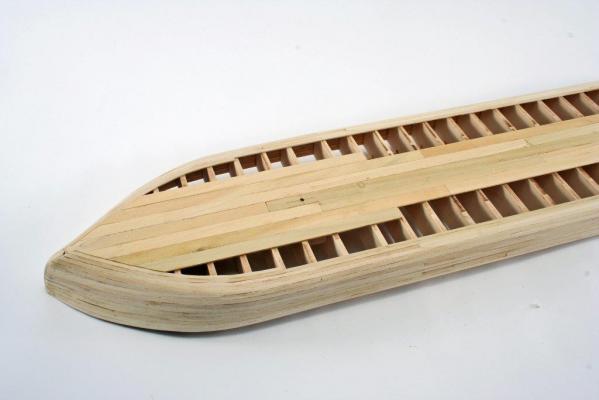
Very nicely done planking. The way you did the stern area is very nice and much better than a straight line. An absolutely beautiful model. Kurt
-
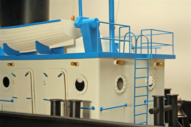
Rod: I hope you sign on to the NRG. We are going to press with the next issue of the Journal next week so sign up soon to get the latest issue. Sometimes kit manufacturers just do weird stuff - I think the water inlets are one of these - why would there be inlets above the cabin area? That's one nice thing about having access to the real thing to look at and get to know exactly what each component is and what it's used for. Always loved tugs from afar but once I was able to touch and feel them it was even better. Part of my deal when I started building models of the tugs for Egan was that I got to go out on each of the tugs for "research" but actually more like joy rides. Got to go on many trips to grab a barge from someplace or drop one off. One memorable trip was on Lake Michigan from Whiting, IN to the Cal Sag Canal on December 30 with the Lake iced over. Pushing the tanker barge through the ice was neat - I was toasty warm in the pilot house - but the deck hands were out on the head of the barge coming out of Whiting till we got onto the Lake and then again once we hit the canal till we parked it in Lemont. They really earn their money. That trip was on the Becky E that was in the one photo. Take care, Kurt
-
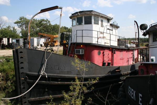
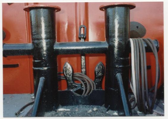
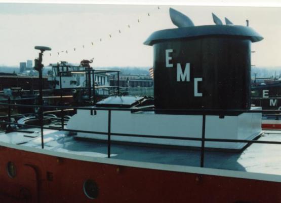
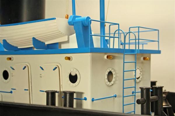
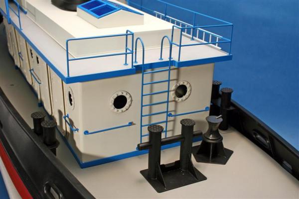
Rod: I don't think those are water inlet ports both from the size and from where they are located. Tanks tend to be on the perimeter of the hull with filling ports either against the superstructure or the bulwarks. What I think these are from the size and location would be escape hatches from the engine room areas. Tugs always have some sort of escape hatch through the deck - usually forward and aft. This is my guess on the subject. As to the Alice E model - it predates MSW by a bunch. It was commissioned by the tug owners and resides in their corporate offices a few miles south of me on the Chicago Sanitary and Ship Canal part of the IL Waterway and the route from Lake Michigan to the Mississippi River. No plans existed for the build but I was able to get on it anytime I needed and measured and photographed all the details - made the drawings necessary and built it up. I attached a few photos of the actual tug - the stern towing bitt and the stack. The photo of the Becky E is almost a sister of the Alice E (both started life as DPC tugs during WWII) but with the original pilothouse.. These are the few that I have scanned as the model was built when I was using my Canon F1's and film. The two photos of the model tug - again from the days before I went digital - are of a model built on the same hull as the Alice E. The tires were cast in Alumalite after making a master in Aluminum of one half of the tire - the ones used on the Alice E. were off 747's that were obtained from O'Hare Airport and nobody makes a 747 model in 1/2" scale to get a master tire to copy so the Aluminum master. Easy to make as the tires have 5 grooves around the circumference with one centered making a perfect joint for the halves of the model tires. Took 38 on the Alice E. tug, I don't remember the count on the other model. Take care, Kurt
-
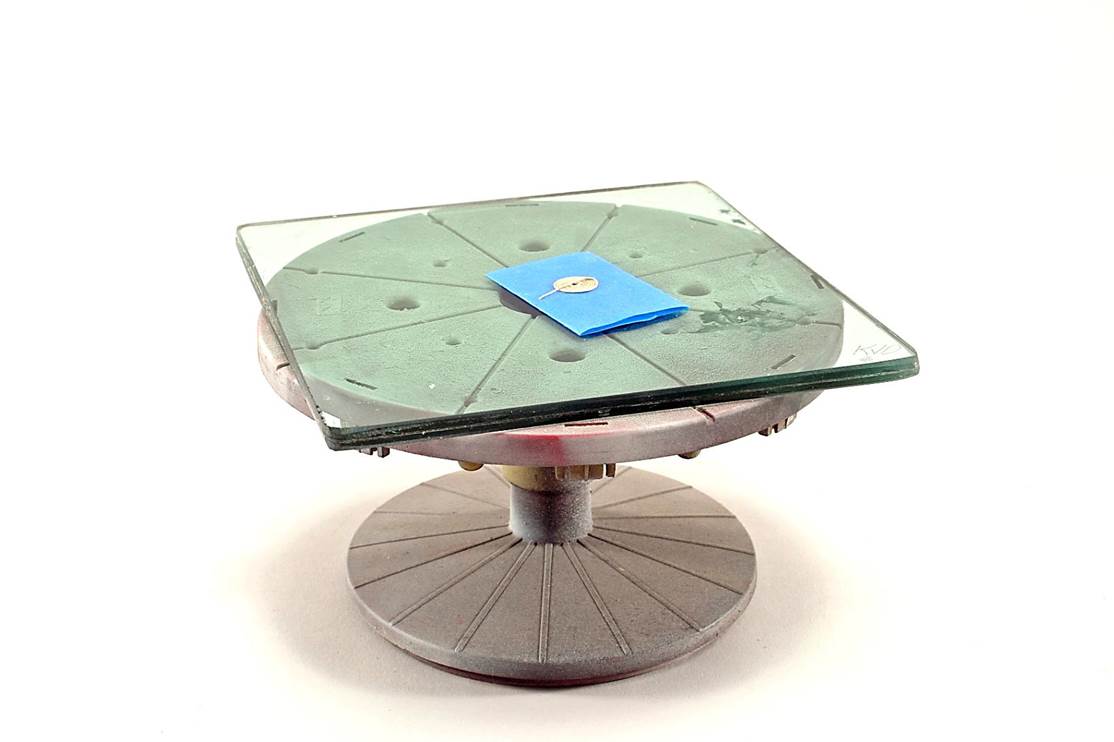
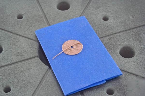
Here are two photos of the turntable set up I use to make rope coils. The turntable is by Tamiya for the spray booth - where I use it a lot. I have several pieces of the glass so I can use one for each rope coil as they dry. The blue painters tape is doubled over and the end of the line is stuck down and the turntable is rotated while pushing down onto the line to make the coil. Once the coil is made to size I apply dilute white glue and set aside till dry. It lifts off the tape easily and can then be glued down in place. The turntable is about 6" in diameter - just FYI. Kurt

- 440 replies
-
- 4
-

-
- niagara
- model shipways
- (and 1 more)
-
Ken: Like Brian suggested, dilute white glue will do the job perfectly. I would use a small piece of something between the rope and deck until the line is coiled, slip the coil onto the deck in the final location and the dilute white glue will do a good job of attaching the coil to the deck. I usually do the coils off the model and add then as you had planned with some dilute white glue used to hold them to the deck and to hold the line from the gun in contact with the coil. I use a small turntable to make the coils. I use some double face tape, or double over some blue painters tape, and stick the end of the line down securely and while turning the turntable I stick the line down into a coil and when the coil is the right size I apply the dilute white glue and set it aside to dry. Another piece of tape and some more line and I can turn out coil after coil like an assembly line setting each coil aside to dry. Your job looks great so it's working for you. Kurt
- 440 replies
-
- 2
-
-
- niagara
- model shipways
- (and 1 more)
-
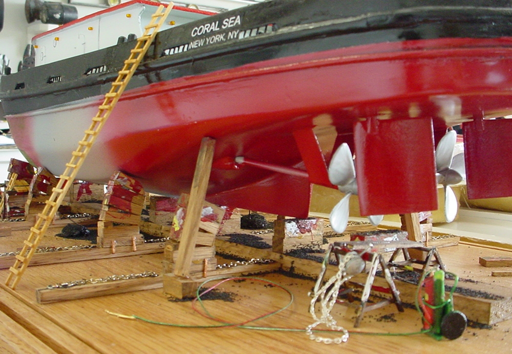
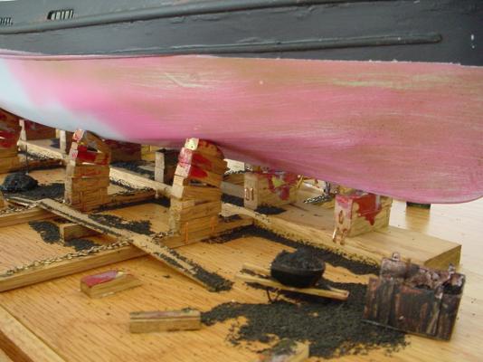
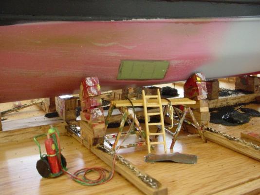
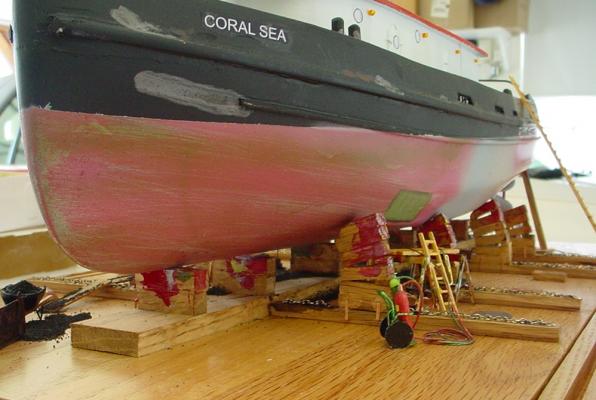
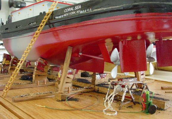
Rod: That's my model of the ALICE E. tug that you wanted to build a similar mounting for your tug. Here are some photos of a friends tug model. He ran a shipyard so knows what the real dry dock stuff looks like. I want to do something similar one day. Kurt
-
Cathead: You have attached the plank on the outer edge of the deck extensions at the bow - a compound curve, the same as the shear plank would need to follow - if I am not mistaken. Why can't the planking start at the shear down and be clamped in place? How was the plank on the extensions fit to the curves? I think that Basswood planks would follow the shear and curve of the bow if wet and bent into place. Maybe I am missing something but it looks like you can clamp the wet plank in place with everything being open - it will take an edge bend if not too wide. Steam bent planks are edge bent on full size craft all the time as well as spiled. Kurt
-
Cathead: I don't have the time to consult my historic photographs of steamboat hulls under construction - actually if they were more accessible I could make the time - It's digging them out of storage that is the problem - but I don't think you have a problem. I built the Chaperon kit from Model Shipways some time ago and the planking was very straight forward with very little spiling needed. I have attached a photo of the Chaperon under construction. Starting at the shear, wet the plank and clamp it in place to dry and then follow the shear down to the turn of the bilge as I did. The kit provided wide planks for the bottom and I used them as the model is mounted w/o the underside being visible. I didn't take photos of the stern area but it was just as easy - like somebody here said, these guys were not master shipwrights - so they did things the easy way. Check the instructions for the Chaperon from Model Expo's web site - page 6 has color photos of the entire planking process. http://www.modelexpo-online.com/images/docs/MS2190/MS2190-Chaperon-Intructions-WEB.pdf I hope this helps, Kurt
-
Brass Black
kurtvd19 replied to sailor jim's topic in Discussion for a Ship's Deck Furniture, Guns, boats and other Fittings
Paul: It sounds like you might have used the Birchwood Casey on brass that was on the model - if so it needs to be neutralized or you will have issues down the road. Normally the parts are rinsed with water after blackening and then attached. If the pieces are on the model you need to "rinse" the parts in some manner. I have blackened stropped blocks by rinsing the wooden blocks and the brass stropping in running water w/o any problems but recently came across a block that had fallen under the bench after blackening but before rinsing and the wood was marked with a dark blue color that does not rinse out. If I am assuming incorrectly please disregard my warning about the ned to rinse the blackened parts. However, if I am correct then you might want to use a baking soda water mix to stop the chemical process and then use water to rinse away the baking soda mix. This could be done in the same manner you applied the blackening agent. Kurt -
How would you improve your Byrnes tools?
kurtvd19 replied to Keith_W's topic in Modeling tools and Workshop Equipment
Thanks for the clarification. Just couldn't envision a depth adjustment but I know exactly what the length adjustment is. I got the optional height adjustment for my Preac when it was first introduced at a NRG conference. Charlie sold every one he brought to the conference as it was a real pain to adjust before the optional device - and only a bit better with it - but anything helped. Kurt -
How would you improve your Byrnes tools?
kurtvd19 replied to Keith_W's topic in Modeling tools and Workshop Equipment
Jheart: The sliding table for the Preac sounds interesting. Can you show a photo? The adjustable depth stop feature has me stumped - it sounds like it would make adjusting the depth of cut on the Preac as convenient as adjusting the depth of cut on the Byrnes saw. I have both saws and use them both but the hassle of adjusting the depth of cut on the Preac means I use it less than I would if the depth was easier to adjust. I would sure like to see a photo or two of the depth adjustment feature. Kurt -
Ken: With the (relative) mass of the guns I back up the glue with a pin of some sort either hidden in the carriage or on the bottom side of a wheel. Using brass for the wheels you can't use a pin there but some cross piece of the carriage will serve. Depends on the pin but that might be adequate to hold the gun in place regardless of your moving the model around later. Bite the bullet and order your rigging line from Syren. You can't get better line unless you make your own and then you will need to practice a lot to get the results Chuck gets after making or buying a rope walk, etc. The only stuff that comes close to Chuck's is Morope and Morope has a nasty tendency to come unraveled when cut and it's more expensive for less line. Morope comes from Germany whereas Chuck makes his stuff right here in the US. Kurt
- 440 replies
-
- 3
-
-
- niagara
- model shipways
- (and 1 more)
-
How would you improve your Byrnes tools?
kurtvd19 replied to Keith_W's topic in Modeling tools and Workshop Equipment
Boyd: The saw is perfect for cutting strips from sheets. As to the tilting table it depends on how many bevel cuts you need to cut on the edge od a sheet or strip. Something that Jim told me after I mentioned that it was a bit awkward to use the tilting table was to add a wedge under the saw base to tilt the saw so that the tilting table is parallel to the table top. I tried it and that works great. The tilt feature was great and got me through a commission and paid for itself in the time saved when I had to make a whole bunch of working 1/72 scale barge covers for a legal job. Kurt -
Ken: You took the suggestion a bit further than I had anticipated with the adjustments for doing the carronades too. Great job on it. The extra time and effort will certainly pay off when you are able to use it for other models, something I hadn't envisioned. Beats making anew one for each model. Take care, Kurt
- 440 replies
-
- 3
-
-
- niagara
- model shipways
- (and 1 more)
-
You can "stack" slitting blades to come up with the exact saw kerf you want for model work. Thurston sells all sorts of blade widths, just have enough so you can stack the necessary blades to get a kerf equal to the dado you want to cut. For our work the saw has plenty of power to do shallow dados. You would want the wider blades on the outside with the thinner blades sandwiched in between so no worry of the thin blades deflecting or heating up and warping as they are prone to do. Any dado being cut in our model work is not going to be all that wide or deep. Kurt
-
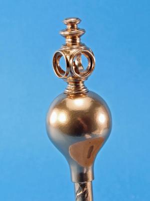
Here is an example of the Krylon Gold Foil paint on a whitte metal casting from the Steam Pumper that Ken Foran designed for Model Expo. This was done with the rattle can. The white metal casting was cleaned up a bit and then primed with Badger STYNLREZ white primer. I can say with confidence that one can't tell this apart from a plated piece. Kurt
-
Jerry: The Krylon foil paints are great - also got the tip to use them from Ken Foran. I have decanted them from the spray can to use in my airbrushes and they are great that way too - better control than by the spray can. I did use some decanted foil paint with a brush to touch up some small areas on a build and it worked OK for that too. I don't know how it would be applied by brush to a larger area though. One point on these paints - they are to be applied over a white primer undercoat. I think it's more for the color than the sticking to the subject. Kurt
-
Ken: It's looking good. When you do up the gun tackles consider making a jig with the eye bolts on a vertical piece and the deck being attached to the vertical piece with the deck eye bolt in the right position and do the gun rigging separate from on the boat so nothing is in the way. As to ME supplying what is on the kit parts list I have had very few issues over the years. I can't remember the last time I was short a part or a bunch - as to the right number of pieces like eye bolts as Ken ran into I think that's the kit designer's fault - though it would be nice when this is brought to the attention of the kit mfg that they fix the problem for the next run. I have seen ME and Bluejacket respond quite quickly to this type of input. When this happens drop an email right to Marc Mosko at ME - he's on top of things like this. So is Bluejacket - a call to Nic would straighten anything like this out there for sure. Kurt
- 440 replies
-
- 1
-
-
- niagara
- model shipways
- (and 1 more)
-
Yes, heat it red hot and drop it into water. It will bend very easy then. Kurt
- 308 replies
-
- 4
-
-
- finished
- model shipways
- (and 1 more)
-
comparison of masking tapes
kurtvd19 replied to vaddoc's topic in Painting, finishing and weathering products and techniques
Duff: I don't always spray the base color against the tape as I have a lot of practice using the Tamiya and 3M tapes and usually know that they are very well sealed against any bleeding but when it is critical and not easily repaired or I have the slightest doubt about the seal I go to the base color spray. It doesn't hurt to do it all the time and if you don't airbrush/mask a lot then it is good insurance. As long as the spray is light there will not be a buildup on the tapes edge which can be harder to fix that some bleed at times. Practice, practice, practice. Kurt -
2015 NRG Conference Update - MYSTIC
kurtvd19 replied to Chuck's topic in NAUTICAL RESEARCH GUILD - News & Information
An update on speakers. Michel Mantin, former Editor of Neptunia, and NRG member from France, will speak on a WWII Japanese Battleship project he is working on. Kurt -
comparison of masking tapes
kurtvd19 replied to vaddoc's topic in Painting, finishing and weathering products and techniques
I have never used parafilm but it is pretty similar to friskit that I have used - which doesn't bleed - but if possible treat it like tape and take all the precautions, being sure it is down tight, edge sprayed with base color, etc. Another tip - always pull tape off by pulling it back over itself - never straight up, a sure way to lift the underlying paint. Kurt -
comparison of masking tapes
kurtvd19 replied to vaddoc's topic in Painting, finishing and weathering products and techniques
When trying to make sure that paint does not seep under the edge of the tape a good start is the Tamiya tape or 3M Fine Line tape used in auto body painting and by many custom painters of motorcycles and helmets. It is important to burnish the edge of the tape down onto the surface. The 3M tape and the Tamiya will change the color of the tape slightly due to the close contact with the underlying surface when the burnishing is adequate. A further method of avoiding paint seeping under the tape is to hit the edge of the tape with a light spray of the underlying color (the paint onto which the new color would seep) at the edge of the tape. This assures that if any paint were to seep under the edge that it is the same paint color and is not seen. Another tip is to avoid spraying with the new color directly at the edge of the masking tape. This can force paint under the tape if there is the slightest imperfection in the burnishing of the tape and it will also help to avoid a built up ridge of paint at the edge of the tape. Tamiya and Frog tape are not the same thing - Frog tape is much thicker. I had high hopes for it but I do not use it in my shop anymore after my testing showed it is very good for household painting but not models. I pass these tips along to all the workshops I do on airbrushing, they will help your painting. Kurt