


trippwj
-
Posts
3,152 -
Joined
-
Last visited
Content Type
Profiles
Forums
Gallery
Events
Everything posted by trippwj
-

ROYAL CAROLINE 1749 by Doris - 1:40 - CARD
trippwj replied to DORIS's topic in - Build logs for subjects built 1501 - 1750
This is truly spectacular! Thanks for posting it here - there are some amazing things to learn from this one!- 883 replies
-
- 2
-

-
- royal caroline
- ship of the line
- (and 1 more)
-
Glad that worked out for you - have looked at these as something to learn with as well. Let me know, please, how it works out!
-
CB - looks like you are off to a good start! I just got my ECB this week and am chomping at the bit to start, although She Who Rules The Shipyard has issued a management directive stating that one current vessel must be launched before the third can be started. Hmmm...guess I need to finish rigging and detailing the Harriet Lane!! Will grab a seat here in the corner near the coffee maker and follow your build to get ready for when i can start!
-
Very nice looking model, Sarah! So wood, paper, and now metal...you've definitely got the "bug"!!! Enjoy!
-
VERY nice Popeye...look forward to the next installation! Just needs a bait bin and sorting table, maybe a cooler full of cold beverages (it gets hot on the water during the summer, you know) and scale rubber bands for the lobster claws!
-
Depending upon the era in question, you may want to look into Karl Heinz Marquardt, Eighteenth-century Rigs & Rigging which is probably the most comprehensive on rigging (merchant or naval) during the 1700's. For general model building, the "classic" works by Charles Davis are still of use - The building of a wooden ship; The Ship Model Builder's Assistant; American Sailing Ships - their Plans and History; The Built-up Ship Model; and Ship Models and How to Build Them
-
I should be home Friday so by Friday night should have first pics up.
-
My Emma C. Berry arrived last night...and of course I had to drive to middle Tennessee today. Bummer!
-
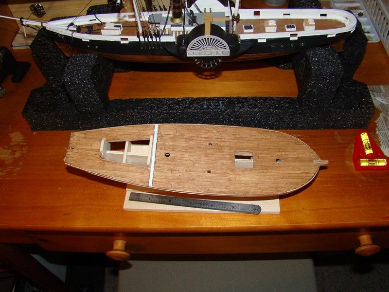
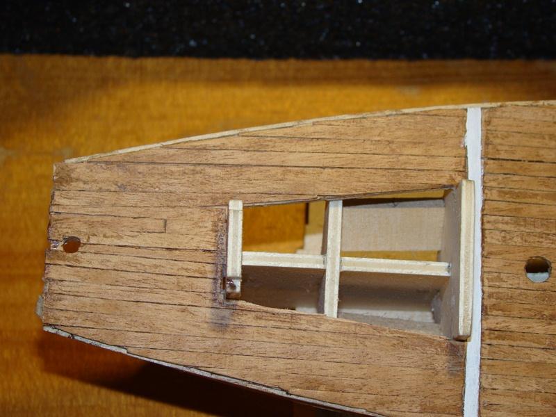
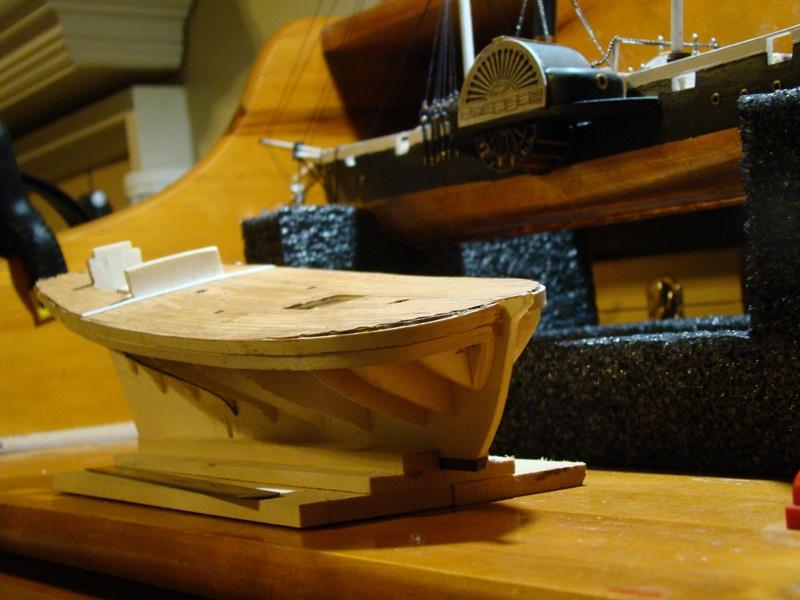
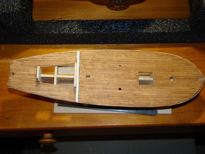
The United States Coast Guard's official history began on 4 August 1790 when President George Washington signed the Tariff Act that authorized the construction of ten vessels, referred to as "cutters," to enforce federal tariff and trade laws and to prevent smuggling. Known variously through the nineteenth and early twentieth centuries as the "revenue cutters," the "system of cutters," and finally the Revenue Cutter Service, it expanded in size and responsibilities as the nation grew. The United States Revenue Cutter Service was originally established as the Revenue-Marine, and so named for over one hundred years, by then-Secretary of the Treasury Alexander Hamilton in 1790, to serve as an armed maritime law enforcement service. Throughout its entire existence, the service operated under the authority of the United States Department of the Treasury. Between 1790 and 1798, the Revenue-Marine was the only armed maritime service of the United States, as the Navy had been disbanded. Each cutter captain was answerable to and received his sailing orders directly from the Collector of Customs of the port to which his ship was assigned. Good records on many of the earliest Revenue Cutters are hard to find. I am using information provided on the USCG Historian's website as well as in Howard Chapelle The History of American Sailing Ships and Donald Canney's U.S. Coast Guard and Revenue Cutters, 1790-1935 as primary historical resources, and will mention other references as I move through the build. I originally started this build last summer and have gotten to the stage of planking the hull. I do not have any early photo's unfortunately. One of the earliest challenges was deciding upon the scale - the plans indicate that they are at 1:64 scale, while the instruction book is listed as 1:50 scale. Hmmm...first disconnect was figuring out which scale to use! If I converted the length on deck at each scale, the 1:50 was far smaller than the known cutters of the time period built to the Doughty plans. The dimension checked out at 1:64, so first decision point passed. Now I just need to be careful when i use any of the instruction drawings that are, supposedly, to scale for the build! Next was deciding on the actual cutter to build. There was no 1823 USRC Ranger (the kit name). I had a choice of several similar topsail schooners, but opted for the Detector. The Detector was built in 1825 by Fisher & Webster of North Yarmouth, Maine. She was stationed in Portland Maine for her career. I like the USRC Detector - my Admiral was an instructor for several years on Radiation Detectors, so thought it would be a good way to pay her some honors. Here, then, is my progress to date on the Detector. i work on her a little at a time when I hit a roadblock on the Harriet Lane. Enjoy! I had to re-plank the aft section as the original planking started to converge following the deck shape not straight from the foreward planking.
-
Farawayman - You make some very good points in your posts (I also apologize for going the humor side above). I think that there may be some approach that would make sense - I am just not familiar enough with the subject to know what it is. I tend to agree with Chuck - when copyrighted material is posted with out appropriate citation or permission, it needs to be pulled. Enforcing the onward distribution of content, however, is nearly impossible for a site. Note that Google and Bing are frequently shown as online here as illustrative of the challenge. While, as an individual, I can add a copyright notation to my pictures, posts and so on, knowing if any of them are actually being used by anyone else, whether for profit or whatever, is likely to be more time consuming to monitor than it is worth for me (plus, if they find any of my model efforts worth claiming, then more power to them - I ain't that good!). I would suggest a look at the basic members agreement as a starting point, perhaps adding that posting of copyrighted materials without permission or in violation of the fair use doctrines will result in removal of the materials immediately (or something along those lines). Back to looking at my model in progress across the room whilst doing my paid job (which has nothing to do with ships, wood, glue, or sails) - and thank you for bringing this topic up for discussion!
-
Hatch covers.
trippwj replied to mikeaidanh's topic in Discussion for a Ship's Deck Furniture, Guns, boats and other Fittings
I think that, for loading, the individual hatch would be removed and stacked to the side. It seems reasonable that some form of lift (probably not the right term) would be rigged from the mast forward of the hatch to lift and lower the barrels, crates and sundries into the hold. I need to do a bit of digging to see what the layout on the Surprise was to see if that makes sense for loading barrels into the magazine.See the plate from Steel's The Elements and Practice of Rigging And Seamanship, 1794 below for an example. -
You Uncle Pauly must work in the same field as my Uncle Guido...Guido is actually a kneecap specialist
- 20 replies
-
- 4
-
-
- IPR
- right of use
- (and 1 more)
-
Question about 17th century spritsail topmast
trippwj replied to Ilhan Gokcay's topic in Masting, rigging and sails
I don't think there were any that had both - Anderson was commenting on the fact that during the 50 year or so period, there were some ships with a spritsail topmast and some with a jib and stay sail. No record of any single vessel that actually had both rigged. It is possible that a ship orginally rigged with a sprit sail top mast could have been modified to remove the topmast and add a jib boom and the staysail, but not likely it happened much. I think you would be very safe staying with only one or the other (Spritsail topmast or jib & stay sail). -
Hatch covers.
trippwj replied to mikeaidanh's topic in Discussion for a Ship's Deck Furniture, Guns, boats and other Fittings
Mike - the answer may depend in large part on the vessel. Are you looking at a merchant ship or a naval ship, and what era? -
Pete - you may want to contact Model Expo (maker of the Model Shipways line of models) and see if they can provide you with a better set of instructions. They tend to be very responsive and exhibit good customer service. They have several sizes of the kit listed when you search for Lifeboat. Good luck!
-
She is looking very good, Sjors - you have some great skills! Enjoying the build.
-
Very nice work, downeaster. We used to live in Orrington - still have family there.
-
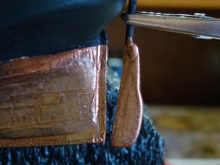
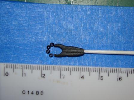
I had been trying to figure out how best to copper my rudder. I tried a couple of copper tapes and plates but couldn't get a good contoured fit. After trying several copper paints I came across the Testor's Copper #1155. Voila! Also continuing work on the main boom. thanks to a suggestion from Adam (skerryamp) I found some teensie weensie timey whimey glass beads at my local Hobby Lobby store. These are labeled as 11/0 seed beads and measure 2.2mm diameter. Still a tad larger than I would prefer, but they will do!
-
On these chain pumps, the volume/mass removed per minute is more a factor of the capability to turn the crank at a high enough rate. Larger diameter pipe would mean more water in each deisk, more mass/weight to be lifted. At some point, a critical relationship between strength of materials, crank speed and crew strength gets crossed. I know in firefighting, we use 4 inch diameter hose from the hydrant to the pumper. At hydrant pressure we get between 750 and 1250 Gallons Per Minute delivered to the pump.
-
Looks like a great way to keep going during the move!
-
fantastic job on the lobster traps! What are you contemplating for hardware on them? Most would have minimal metal (rusts too easily and ruins the wood). perhaps a cobblestone or old chunk of granite in the house for a weight? Lobsters on water skies....interesting visual!
-
Thanks, Adam - hope to get at least a small update posted today. Had been pondering how best to handle coppering the rudder, you may recall. Using the tape was not viable - just didn't look right. Tried the plates but same problem. Also, an update on Cricket's cosntruction assistance (Cricket is my 5 year old apprentice). Tune in later today for what seems to have worked for me for coppering the rudder and assembly by Cricket!
-
Lookin' good, Adam - good catch there, but then again, who really needs a tiller anyway????
-
Sarah - will wait for others on the first 3 (I made some guesses on mine), but as to #4 (that speaker looking thing) - that is the shaft for the paddlewheels. What looks like a box is actually bushings - if you look at the end view you can see it as just a shaft between the house and the paddle box.
-
Hi there, Sarah. Yep - very basic info on the deckplans so a lot of room for individuality. I got stuck for a bit trying to figure out what the coaling rings are. Found out (via ModelShipBuilder forum) they are essentially like a manhole cover where coal was loaded. Based on a bunch of digging etc, the ones on the HL would be about 18 inches diameter, nearly flush with the deck. See the build log by Clare here for how he did them. http://www.modelshipbuilder.com/e107_plugins/forum/forum_viewtopic.php?6849