
Check out our new MSW Sponsor Innocraftsman
×


dafi
-
Posts
2,416 -
Joined
-
Last visited
Content Type
Profiles
Forums
Gallery
Events
Everything posted by dafi
-
 Nice and crisp build! Daniel
 -
Hy Popeye nice to see you working on a real ship ;-) Love it :-) Daniel
-
HMS Victory by Yon - Caldercraft 1:72
dafi replied to Yon's topic in - Kit build logs for subjects built from 1751 - 1800
Hello Yon, great work :-) Daniel -
Nice :-) Still producing some flags for the locker? XXXDAn
- 1,319 replies
-
- 1
-

-
- caldercraft
- Victory
- (and 1 more)
-
So the before last part, and I keep the usual length, as always the showing how to was the important, not just showing the end results. So here comes the revised binnacle. Well chucked the grooves on the backside provide help in placing and bending :-) Using a hard and crisp tool to bend ... ... loosened after the first step, a doubled paper being put underneath for a tad of extra height, retracted the paper and by rolling with a wooden rod the corners are subdued into perfection. The most tricky is always the last bent. Here for I used Tesa double sided tape to fix the part on the table and inserted a 3 mm Plexi and bending the brass over it - I love when dafi´s well planned brainfarts work out well ;-) Then using fine pliers to adjust the corner´s angles ... ... and we are awarded with a nice and crisp box :-) The lid for the small funnel is formed using a center punch. The inner table should not be too much of a problem after all this :-) Cutting out the binnacle´s top, stacking the layer cake compasses, and adding the needed extra parts: evergreen rod 2 mm for the lantern (a toothpick will be ok too), 1 mm Evergreen rod for the funnel, a 0,2 mm sheet for the inner base (cardboard will work also), 2 Rings for the bracing onto the deck and transparent film for the windows ... ... and just fixed :-) Left the etch-binnacle Mark 1, in the middle the new one with now crisp drawers and right the also rivised rudder column, now with crisp lawrels :-) All the best, Daniel
-
Sorry Harry I did not intend to bore you, it is in a way the months of research behind and the joy of developing and sharing the parts. It came out naturally as result of all those trials I did all along my way :-) It was a tad more then 12 hours and will provide some help to modelers who just want do do some modeling without to much research. Even though this is still the kit section, the most important in modelmaking is not just to glue things together, but even more important is to give a soul to a model - and this no etch part can help the modeler. Greetings, Daniel :-)
-
Just to show, not everything turned out perfect in the first go. Here a trial with open flag lockers: Too much space on the plate, too complicated in assembly and most importend: too little sex-appeal as it looks horrid! So being eliminated with no hesitation for V2 and adding other more sexy goodies instead ... ... so, the bell can be rang :-) XXXDAn
-
I do not think it was empty, as there was something meant to be for heraldic reasons. I my understanding is right, those three feathers are not just feathers, but a crown crowned with tree feathers. So they might have switched a plain crown by one with three feathers, which would go with the strict heraldic rules of those days. Daniel
-
Those feathers were almost present at Trafalgar - being part of the stern decoration of the HMS Prince of Wales but at this moment on the way home with Calder on his own flagship to face court martial because of his tactics at Cape Finisterre,... When the PoW was demolished in about 1822, those feathers were fixed afterwards onto the Vic and stayed there ever since. This is well known, the only thing is, what was there before? The Livesay drawing not really define this place, but as todays side entries also present the coat of arms with a crown in the center, and as the figure had had the crown too, it seemed to me the most logical guess. Any other guesses or solutions always welcome to be discussed :-) Daniel
-
Always great to see this master piece pop up to attention! Love it, great research, wonderful execution, great feel ! DAniel
-
The most tricky part so far, the boarding pikes holders: First glueing two rings atop of each other, the needles making sure, that the holes of the upper ring will be lined properly ... ... while the one on the bottom has pocket holes. Then putting both rings over the mast ... ... and cutting the same amount of holes on both rings away until the diameter fits properly. Taking a pike and sorting out the heights for that the beautiful point of the spear does not disappear in the ring. Then glueing first the inside of the upper ring onto the rubbing pouch and let dry well. Afterwards bend into place and fix it on the other side and in the back. Use one pike for the alinement of the two rings and fix the bottom ring also in two steps. Then take out the pike and bend carefully straight and horizontal and glue it to its final position ... ... and fill with the boarding pikes. With a tad of color and rope it could look like this :-) As I always moan about the Prince of Wales´ feathers, it is time to sratch them off and replace them by a cute five piece crown - a pure dafinistique hypothesis :-) ... ... and fix some more stable lamp holders. Amicalement, Daniel
-
Perhaps the reason is to have them ready for emergency. XXXDAn
-
Thanks Popeye, still found an old vintage picture that I wanted to share ... ;-) XXXDAn
-
So tinkertime goes on ... ... the funnel on the forecastle ... ... flaglocker, I opted for the closed one ... ... and the boom saddle and the rack for the pins on the mizzen :-) The belaying pins stay hand-worked ;-) Cheers, Daniel
-
Thank you Popeye, but I think the etch and the new wealth of details is only one thing. More important is not to loose the soul of a model over all this tinkering. Actually I prefere a well build oob with the right heart and soul over a overdetailed "supermodel" that is lacking the smell of the seaside. Nether the less I try both, soul and interesting details, lets see which stories still will araise to be told. Three cheers on modelmaking, Daniel
-
So last night´s tinkering ... ... the spectecal plates of the rudder ... ... the new poop skylight with bending help in the back ... ... roof curved by rolling with a wooden stick over a soft surface ... ... and especially round roof and right number of windows ;-). The fighting top with lantern holder... ... and the stun´sail boom fittings. Cheers, Daniel
-
As the set of my etch parts is already with me and almost ready to be distributed, I am still trying out the last production samples just to make sure everything really fits and also refining my own skills and technics. To prepare the locks I worked hard to cut off the small bit that fixes it to the frame. Also handling and positioning was quite difficult as the parts are tiny. The first idea was to use this bit it as a connector pin :-) So a small hole drilled into position which makes positioning and glueing easier and the lock more stable afterwards. After breaking two 0,4 drills, I got the second idea: Why drilling? A needle does the job better and faster ... ... so a needle fixed in a tooth pick ... ... a small well positioned acupuncture and then using fine pliers instead of tweezers ... ... got it fast and safe on the spot. The fine pliers do not have the tendency to send things into the parallel universes as much as tweezers do :-) Also tried out an alternative to the rings on the breech using etch rings instead of wire. Also a great way with the needle to prepare the fixing holes. Depending to the knowledge and skill of the modeler, the rings can be made a tad more even like this than using wire. And also trying out other ways of working on difficult parts, here the back of a blade in a clamp for bending the bucket holders on the poop. Daniel
-
Fighting ladders
dafi replied to dafi's topic in Discussion for a Ship's Deck Furniture, Guns, boats and other Fittings
For the iron jacob ladders, not to forget: Brady was US Navy and around the 1850´s. So it must be considered that it was a later introduction or american fitting. XXXDAn -
Fighting ladders
dafi replied to dafi's topic in Discussion for a Ship's Deck Furniture, Guns, boats and other Fittings
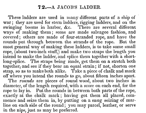
Hello Anja, thanks for the feedback! I already fixed the link parallel to your tries, it should work now. In my understanding the jacob´s ladders were used in different places: on the stern to get into the boats, to the topmasts if not rattled and any other place or swinging booms in harbour. It was rope left and right with wooden battens. See Brady page 39 Chapter 72 nad the plate on the page prior to it. http://books.google.de/books?id=wQxqa5K_zcgC&printsec=frontcover&hl=de&source=gbs_ge_summary_r&cad=0#v=onepage&q&f=false The iron ladders put up the question: Were the wooden battens replaced by iron bars or was the rope replaced by iron bars making it a stable thing? Daniel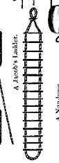
-
Already realised long time ago, that the ladders leading from the waist to the higher decks are disturbing the handling of the guns. It was easy to find out that they were taken out while clearing for action. I remember having read, that prior Trafalgar - I guess it was the Royal Souvereign - tossed some of them over board together with some bulkheads. Luckily for us, the bureaucracy made them record it in the logs, so we of it today ;-) So the question was, how to come up if taken out - jumping down was easy. Freshly found in Brady´s "Kedge Anchor" 1852: Fighting Ladders. These were rope ladders, that apparently sometime stayed permanantly as they provided useful if the wooden ladders were taken out while washing the decks. http://books.google.de/books?id=wQxqa5K_zcgC&printsec=frontcover&hl=de&source=gbs_ge_summary_r&cad=0#v=onepage&q&f=false Page 239, Chapter 440 Were those jacob´s ladders or were they of different design? Daniel
-
Here are the recipes Brady gives in his "Kedge Anchor" 1852 http://books.google.de/books?id=wQxqa5K_zcgC&printsec=frontcover&hl=de&source=gbs_ge_summary_r&cad=0#v=onepage&q&f=false Pages 389- 391, chapters 527, 528, 530-533, 538, 542-544 Most of them with lamp-black, some with rust, also oil, vinegar, spirits, tar or whiskey (!), but all of them applied hot. I guess a decent glossy appearence with sometimes a shade of brown is to be expected? Daniel
-
Here are the recipes Brady gives in his "Kedge Anchor" 1852 http://books.google.de/books?id=wQxqa5K_zcgC&printsec=frontcover&hl=de&source=gbs_ge_summary_r&cad=0#v=onepage&q&f=false Pages 389- 391, chapters 529, 534-537 All of them very dirty and dark mixtures i.m.h.o. Daniel
-
Of course this brings the question up which "tools" were used? In between the guns wooden spoon and knife? Metal spoon and fork if in possession? The officers most possibly used fork and knive here an example out off NMM of normal table wear of 1800 http://collections.rmg.co.uk/collections/objects/62263.html What was about the midis? Also the better table ware, as they were to become officers? Here as a small goody Nelsons fork-knive, also known from other handicapped sailors of the times. http://collections.rmg.co.uk/collections/objects/63222.html Daniel
-
Thank you Mark, Lawrence and Dan :-) The officers used fork and knive, best example is Nelsons fork-knive, also known from other handicapped Sailors of the times. http://collections.rmg.co.uk/collections/objects/63222.html Also an example of normal table wear of 1800 http://collections.rmg.co.uk/collections/objects/62263.html Daniel
-
Thanks Kevin and Mark :-) Still trying to replicate the hard tacks in 1:100, a comrade in my german forum already gave me the recipe: http://www.royalnavalmuseum.org/info_sheet_ship_biscuit.htm But where do I get original lamb for the stew and beef in 1:100 suitable for the needed small portions?!? Fork and spoon? Did the ranks have forks? I would have guessed just knife and wooden spoon in 1805? Any ideas? Daniel
