dafi
-
Posts
2,430 -
Joined
-
Last visited
Content Type
Profiles
Forums
Gallery
Events
Everything posted by dafi
-
Perhaps the reason is to have them ready for emergency. XXXDAn
-
 Thanks Popeye, still found an old vintage picture that I wanted to share ... ;-) XXXDAn
 -
So tinkertime goes on ... ... the funnel on the forecastle ... ... flaglocker, I opted for the closed one ... ... and the boom saddle and the rack for the pins on the mizzen :-) The belaying pins stay hand-worked ;-) Cheers, Daniel
-
Thank you Popeye, but I think the etch and the new wealth of details is only one thing. More important is not to loose the soul of a model over all this tinkering. Actually I prefere a well build oob with the right heart and soul over a overdetailed "supermodel" that is lacking the smell of the seaside. Nether the less I try both, soul and interesting details, lets see which stories still will araise to be told. Three cheers on modelmaking, Daniel
-
So last night´s tinkering ... ... the spectecal plates of the rudder ... ... the new poop skylight with bending help in the back ... ... roof curved by rolling with a wooden stick over a soft surface ... ... and especially round roof and right number of windows ;-). The fighting top with lantern holder... ... and the stun´sail boom fittings. Cheers, Daniel
-
As the set of my etch parts is already with me and almost ready to be distributed, I am still trying out the last production samples just to make sure everything really fits and also refining my own skills and technics. To prepare the locks I worked hard to cut off the small bit that fixes it to the frame. Also handling and positioning was quite difficult as the parts are tiny. The first idea was to use this bit it as a connector pin :-) So a small hole drilled into position which makes positioning and glueing easier and the lock more stable afterwards. After breaking two 0,4 drills, I got the second idea: Why drilling? A needle does the job better and faster ... ... so a needle fixed in a tooth pick ... ... a small well positioned acupuncture and then using fine pliers instead of tweezers ... ... got it fast and safe on the spot. The fine pliers do not have the tendency to send things into the parallel universes as much as tweezers do :-) Also tried out an alternative to the rings on the breech using etch rings instead of wire. Also a great way with the needle to prepare the fixing holes. Depending to the knowledge and skill of the modeler, the rings can be made a tad more even like this than using wire. And also trying out other ways of working on difficult parts, here the back of a blade in a clamp for bending the bucket holders on the poop. Daniel
-
Fighting ladders
dafi replied to dafi's topic in Discussion for a Ship's Deck Furniture, Guns, boats and other Fittings
For the iron jacob ladders, not to forget: Brady was US Navy and around the 1850´s. So it must be considered that it was a later introduction or american fitting. XXXDAn -
Fighting ladders
dafi replied to dafi's topic in Discussion for a Ship's Deck Furniture, Guns, boats and other Fittings
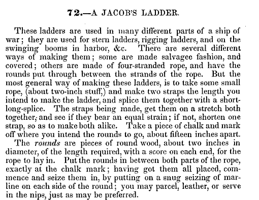
Hello Anja, thanks for the feedback! I already fixed the link parallel to your tries, it should work now. In my understanding the jacob´s ladders were used in different places: on the stern to get into the boats, to the topmasts if not rattled and any other place or swinging booms in harbour. It was rope left and right with wooden battens. See Brady page 39 Chapter 72 nad the plate on the page prior to it. http://books.google.de/books?id=wQxqa5K_zcgC&printsec=frontcover&hl=de&source=gbs_ge_summary_r&cad=0#v=onepage&q&f=false The iron ladders put up the question: Were the wooden battens replaced by iron bars or was the rope replaced by iron bars making it a stable thing? Daniel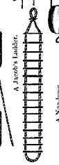
-
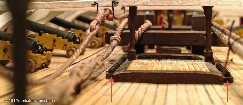
Already realised long time ago, that the ladders leading from the waist to the higher decks are disturbing the handling of the guns. It was easy to find out that they were taken out while clearing for action. I remember having read, that prior Trafalgar - I guess it was the Royal Souvereign - tossed some of them over board together with some bulkheads. Luckily for us, the bureaucracy made them record it in the logs, so we of it today ;-) So the question was, how to come up if taken out - jumping down was easy. Freshly found in Brady´s "Kedge Anchor" 1852: Fighting Ladders. These were rope ladders, that apparently sometime stayed permanantly as they provided useful if the wooden ladders were taken out while washing the decks. http://books.google.de/books?id=wQxqa5K_zcgC&printsec=frontcover&hl=de&source=gbs_ge_summary_r&cad=0#v=onepage&q&f=false Page 239, Chapter 440 Were those jacob´s ladders or were they of different design? Daniel
-
Here are the recipes Brady gives in his "Kedge Anchor" 1852 http://books.google.de/books?id=wQxqa5K_zcgC&printsec=frontcover&hl=de&source=gbs_ge_summary_r&cad=0#v=onepage&q&f=false Pages 389- 391, chapters 527, 528, 530-533, 538, 542-544 Most of them with lamp-black, some with rust, also oil, vinegar, spirits, tar or whiskey (!), but all of them applied hot. I guess a decent glossy appearence with sometimes a shade of brown is to be expected? Daniel
-
Here are the recipes Brady gives in his "Kedge Anchor" 1852 http://books.google.de/books?id=wQxqa5K_zcgC&printsec=frontcover&hl=de&source=gbs_ge_summary_r&cad=0#v=onepage&q&f=false Pages 389- 391, chapters 529, 534-537 All of them very dirty and dark mixtures i.m.h.o. Daniel
-
Of course this brings the question up which "tools" were used? In between the guns wooden spoon and knife? Metal spoon and fork if in possession? The officers most possibly used fork and knive here an example out off NMM of normal table wear of 1800 http://collections.rmg.co.uk/collections/objects/62263.html What was about the midis? Also the better table ware, as they were to become officers? Here as a small goody Nelsons fork-knive, also known from other handicapped sailors of the times. http://collections.rmg.co.uk/collections/objects/63222.html Daniel
-
Thank you Mark, Lawrence and Dan :-) The officers used fork and knive, best example is Nelsons fork-knive, also known from other handicapped Sailors of the times. http://collections.rmg.co.uk/collections/objects/63222.html Also an example of normal table wear of 1800 http://collections.rmg.co.uk/collections/objects/62263.html Daniel
-
Thanks Kevin and Mark :-) Still trying to replicate the hard tacks in 1:100, a comrade in my german forum already gave me the recipe: http://www.royalnavalmuseum.org/info_sheet_ship_biscuit.htm But where do I get original lamb for the stew and beef in 1:100 suitable for the needed small portions?!? Fork and spoon? Did the ranks have forks? I would have guessed just knife and wooden spoon in 1805? Any ideas? Daniel
-
Thank you Mark, there are several jars, jugs and small and medium casks and buckets missing: among others (not yet identified) there should be fresh water barrel on the beam, freshwater jar on the table, bucket for catching/bringing the food, and not to forget, the bucket for the "processed" food on days that the heads were no option weather wise - buck´t and chuck´t :-) The small model gave me the impression, that chests were no suitable option for the big man of war. If I look at the space and see that 17 man were confined in there, even shoe boxes would not work. Also the question is, how in clearing for action 800 chests were to be managed?!? Duffels were easy to be thrown in the hold - or elsewhere. Even as protection against splinters. Managing and stacking chests in that quantity is much more of a task under clearing circumstances. Seen this thoughts, the option shown in AOTS Bellona with the duffle bags hanging both sides of the ports in between the knees seems the most logical. I do for some reason not believe, that the sailors had a chest stacked in on of the lower decks. All the best, Daniel
-
Just discovered in AOTS Bellona: A sketch of the hammoc nettings - the hammoc much more looking like Cannon balls :-) - showing the protecting cover. The index says: "Cover (tarred before 1780, painted afterwards)" I suppose that this was a rather light tarring for not spoiling the hammocs?!? Daniel
-
Thank you all :-) @Popeye: I do not know of racks in between the guns as this would interfere with the handling. As far as I know, extra shot was kept in nets/tarpaulins in the ships center line. Daniel
-
As always, if curious, have to try out ... ... easy to see, it is getting tight. One place has to stay free because of the hanging knee. Still missing some jugs and a handful of barrels and the duffels in the corners. There were about 800 seamen living, eating and sleeping on the area of the decks, means 400 each deck. As the aft was reserved for ranks so the remaining area was about 12 guns long each side. This makes a count of 400 / 12 / 2 and gives about 17 people each mess. So I understand the shift system with the watches, as there is maximum space for 11 or 13 people on the table. All those 17 people´s belonging had most possibly also to be stored in that confined space ... ... just some thoughts ... DAniel
-
... these ones?!? ...hihihihihi.... Thank you Sirs, but cleared for action is the most boring one in my opinion - just guns and their equipment, everything else stripped ... ...boooooring ;-) Daniel

-
Here we went on in the lower deck, getting tighter ... ...first table dummies ... ... followed by some real model making ... ... first sitting trials ... ... and tight we go. bom apetite! XXXDAn
-
ROFL!!! THIS made my day! Thanks for the wonderful input, Daniel
-
The usual stunning research and execution :-) Bravo!!! With a deep bow, DAniel
-
A always nicely presented little detail in many films: The names painted onto the carriages of the guns. To be seen for example in MaC in the first scene on the gun deck. Fiction - means invention from writers and film makers - or are there any historical hints or proves for it? Thank you, Daniel
-
Great work! Cheers Daniel
-
Hello Robin and Fortres, thank you for the pictures above :-) There are some glitches in Turners drawing of December 05. I do not know if these things are really guns, there is much discussion about it. Also the position of three of them on the poop rails is quite uncommon. Also are to be seen woolings on the mizzen - repairs from Gibraltar still as the great repair was done with iron loops? Some guessing was done, if he did the drawing on board - it seems to have snow and therefor was cold - or if he finished or even did completely by memory afterwards in the studio. Turner was in first place an artist, and reality had to step back behind the artistic expression. See the first painting of the ship of the line, how exaggerated the heights are - looks like a 12 story building, people standing in the gunports ... Also the last painting was quite controversial if I remember well - it was a contract work by the marine and he melted several stages of the combat into one picture - not to the delight of his clients ... All the best, Daniel