dafi
-
Posts
2,430 -
Joined
-
Last visited
Content Type
Profiles
Forums
Gallery
Events
Everything posted by dafi
-

Royal William by derebek - 1/72
dafi replied to derebek's topic in - Build logs for subjects built 1501 - 1750
Wonderfully done :-) Congratulstions for the results! Daniel -
Wonderful and lovely job :-) XXXDAn
-
HMS Victory by EdT - FINISHED - 1:96 - POB
dafi replied to EdT's topic in - Build logs for subjects built 1751 - 1800
As always: Big thanks for showing the how-to-do :-) Always an inspiration! Daniel -
Love it :-) Daniel
-
Thanks Brian, Paul and Mark, as always, I do not know yet what this is for, just a small nagging voice inside my head told me to do so ... XXXDAn
-
ancre LE BONHOMME RICHARD by Jeronimo - FINISHED
dafi replied to Jeronimo's topic in - Build logs for subjects built 1751 - 1800
Wonderful as always!!! Daniel- 662 replies
-
- 1
-

-
- bonhomme richard
- frigate
- (and 1 more)
-
But still the question: Is it the same result on the guns as the contemporary paints? So we are having three different types of guns: brass, iron and steel. Each different in the upkeeping :-) Daniel
-
And the weekend show, some quantum leaps - means very small and little :-) fitted the last lid ... ... and fitted with lanyards. The holes in the brass fittings were deepend into the plastic by means of a hot needle ... ... so the brass is not damaged like with a drill and the deep is automatically fixed by the cones of the needle tip and the size of the hole in the fitting ... ... and it looks like this. Grüßle, Daniel
-
Hello Jürgen, nice to see you here! All the best, Daniel
-
Thank you both Garward and Maurice! @ Garward: It is always a treat to see your wonderful and precise models! Thanks for linking to the blackenig of your wonderful barrals! If I got it wright, this are the means of blackening the model parts. I also look very much onto who the original guns appeared when being blackened. Do you have any sources of that too? @ Maurice: As always, you pull exactely the source that was in my mind! Bruzelius´great collection of original sources. I edited the titel of the thread to make more precise: How was it done in the old days and especially, how did it look like? Cheers, Daniel
-
If my memory serves me well, the "paint" for blackening the guns consisted of turpentine, tar, rust, and other components, cooked and applied hot. But I cant find the recipe any more, but I recall it being out of a contemporary source. Any clues where to find that? And coming with that: Any clue how the painted barrels looked like? Glossy brownish shining appearance? Thanks for any enlightenment, Daniel EDIT: Precised Titel
-
Here both versions side by side, same ship, only 40 years of difference in between ... ... fascinating, as a good friend of mine would say ;-) Got the gun carriages messed and gave a brownisch oil coat to the barrels as some of the ingredients - rust and tar - suggest ... ... and the tompions plain without color, sticking out and not todays fancy thread in the middle, as the artifacts in NMM and museums suggest. Just one try with a line that goes around, but it does not look to convincing. The shoe for the anchor was fixed in the appropriate place and that is the thing for the moment :-) Cheers, Daniel
-
Sooooooo after some time finally managed to do some new bricotage ... ... fitted the deadeyes ... ... used the revolutionairy Double-Twin-Super-Drive-Technology for grinding the needle heads ... ... put the batten ... ... and it looks even neater than the bits on my Vic :-) Too take this back added some paint and rust ... ... and tomorrow once the paint is well dried, I can take it back a tad and do the finetuning :-) Lieber Gruß, Daniel
-
... and not to forget the fancy picture of this french 74 ... http://commons.wikimedia.org/wiki/File:Achille_mp3h9307.jpg Enjoy, Daniel
-
Hammock plan of the Bedford 1775, around 1790, ZAZ6793 http://collections.rmg.co.uk/collections/objects/86584.html Some of my shots of the Vic: Open and rolled hammocs This one looks rather tiny, is this something else?? In the cable tier The better standard of the sickbay ... ... also to be found in the cabins under the poop. Cheers, Daniel
-
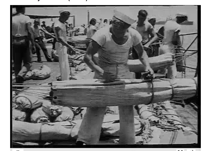
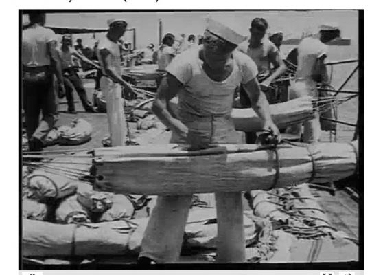
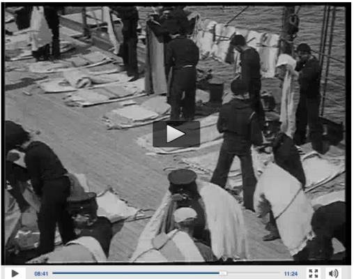
Somewhere here on the board already posted by someone else, but I do not find the original source, here a copy from the document how the Royal Navy was doing the hammocks (thanks to the original poster!!!) http://files.homepagemodules.de/b564537/f129t1616p17024n2.pdf Two drawings out of Brays Album from NMM PAJ1992 http://collections.rmg.co.uk/mediaLib/400/media-400304/large.jpg PAJ1989 http://collections.rmg.co.uk/mediaLib/676/media-676424/large.jpg This is what Nares, Commander R.N. wrote in 1868 http://archive.org/stream/seamanship00acadgoog#page/n222/mode/2upPage 85 And here the US Navy in 1915 doing it still the same way http://www.filmpreservation.org/preserved-films/screening-room/u-s-navy-documentary-1915 see 8:40 Here 2 stills Gruß, Daniel
-
Great work, and save trip, looking forward to see you again! Cheers, Daniel
-
So what would be a dafithread without Dafinism? Already I wondered that nobody did moan, as I did not bolt the channel onto the gunwale but on top of it instead ?!? ... ... ... so dafi does what dafi knows best ... ... DESTRUCTION!!! ... Positively seen, this gave a nice test, if the technic is dafiproof - If I mange to cover up the damages caused by this little action, I am on the right way :-) So fixed the channels on the right hight ... ... coverd the holes with the basic color, first layers with three different shades of brown ... ... and drying-washing of-adding more-and-so-on and it goes the right direction :-) Close enough to the original version, so I am quite happy ;-) XXXDAn
-
Thank you Kevin, this will be another interesting story. Be shure one day it will come :-) And now something completely different ... Even though I cant tell how much colorisation was done afterwards, two interisting versions of the same photo, possibly HMS Implacable. http://www.napoleon1er.org/forum/viewtopic.php?p=342084&sid=ba7bd7589372562542d84e51f725c6f6#p342084 Also nice picture 3, that make my trials look brand new ;-) XXXDAn
-
Just realised, that one part of the basic research was missing here ... I was researching more about the aging of ships. Unsually we tend to display the ships in a freshly build and painted state. Some bold versions show the ships in quite "wrecked" appearances. But I do believe, that most of their life, the ships were somewhere in between. This made me have a closer look. I chose the following 3 ships, as I knew, that there is quite good documentation in the web. First the Neptune in Genove (Google pictures: Neptune/ship/genova), light wooden hull http://www.flickriver.com/photos/jarmi7d/5044918333/ http://www.flickriver.com/photos/peer_gynt/7655543406/ http://www.wanderingoverland.com/?p=855 http://photo.remgo.com/galeone-neptune/ http://www.flickr.com/photos/peer_gynt/8033111211/ http://en.wikipedia.org/wiki/File:Genova-Porto_antico-DSCF7741.JPG http://en.wikipedia.org/wiki/File:Genova-Porto_antico-DSCF7743.JPG http://en.wikipedia.org/wiki/Neptune_(galleon) Funny to compare the freshly painted version with the neglected one. Nice to see the better condition in protected areas like underneath the channels. Exposed areas like underneath the cathead look much more tattered. Was this also on seagoing ships that extreme or is this more of a harboring effect? But also ships spent long times in harbor do to waiting, winter sleep or being in ordinary. And the Gotheburg (Google: Gotheburg, ship), dark wooden hull http://www.flickr.com/photos/maskofchina/311861497/ http://www.lemback.com/the-swedish-ship-gotheborg/ http://viktordonovan.blogspot.de/2011/07/replica-1745-sailing-ship-in-gothenburg.html http://www.lifeinnorway.net/wp-content/uploads/2012/08/goteborg13.png http://foto.arcor-online.net/palb/alben/62/8002362/3530663266666630.jpg By the dark hull, the effects are not as visible like on the neptune. Funny to see the fresh scratch marks on the whales in some of the pictures Then theHMS Surprise (Google: surprise, rose, san diego), painted hull http://www.panoramio.com/photo_explorer#view=photo&position=185&with_photo_id=13424720&order=date_desc&user=2074768 http://www.flickr.com/photos/arejay/165878016/ http://photos.lomara.org/index.php/camera/sandiego/100_0825 http://www.flickr.com/photos/seaveyfamily/215130447/lightbox/ HMSSurpriseQtrbow800.jpg and my favorites: http://xpda.com/junkmail/junk163/pict9071.jpg http://xpda.com/junkmail/junk163/pict9072.jpg Also here by the degradation of the paint, one can exactly tell which year the picture was taken ;-) The difference in between the fresh and the tattered is amazing. Nice to see bleaching, rust, chipped color, algae on the waterline, patches and so Also do not forget: Ships were build over some period, where the wood was alraedy exposed. So even a brand new ship usually was unlikely to show fresh wood in larger areas. But therefor repaired areas would stick out. On the other side I have never seen the patchwork on deckplanks like often shown in plastic models. Amicalement, Daniel
-
Here we go again ... The chainwhales/ancor protection fitted ... ... and remembered the wasp-twins. So painted, redrawn the grooves, guide is the plastic stripe from a labeling machine ... ... and treated the bottom one with a diluted blach ink to enhance structures. The top is the usual clean version Casted new iron brackets ... ... and made more mess. Then added some rust, some scupper delicacies, some rust from all the iron work and some chipped color as nicely to be seen on todays Vic. A bit rough at the first moment, but if one consider the ships being out for months on blockade duty, I believe this was not the worst ... And if one looks at the Surprise in San Diego ... http://xpda.com/junkmail/junk163/pict9072.jpg ... surprise, surprise ... Cheers, Daniel
-
Thank you Mike and Paul. Good hint you gave to the brightwork. http://en.wikipedia.org/wiki/Brightwork XXXDAn
-
Hello Mark, Michael, Mike and Robin, thank you all. Mike, are there any contemporary sources confirming this? Is it really a reddish appearence like I expect by name and contemporary violin paints? Cheers, Daniel
-
So a little bit of basic work. The aim is to explore how a hull could have been looking before the wasp-lines came up. So it should be "paid bright with rosin". Contemporary pictures and models show a light/bright color. If I understand well, it could still have been a bit transparent. In german wikipedia rosin is mentioned to be used for painting violins. Also the sources give rosin diluted with turpetine. Both products are result from distilling resin from special pine trees. Does that mean, that some color was still aded to get the bright look? http://en.wikipedia.org/wiki/Turpentine http://en.wikipedia.org/wiki/Rosin Some contemporary models: http://collections.rmg.co.uk/mediaLib/668/media-668380/large.jpg http://collections.rmg.co.uk/mediaLib/541/media-541666/large.jpg Some contemporary paintings http://collections.rmg.co.uk/mediaLib/484/media-484826/large.jpg http://collectionsonline.nmsi.ac.uk/detail.php?type=related&kv=65421&t=objects http://collectionsonline.nmsi.ac.uk/detail.php?type=related&kv=65431&t=objects Here some pictures that Blue Ensign was showing in another thread, thank you! http://www.bbc.co.uk/arts/yourpaintings/paintings/a-sixth-rate-on-the-stocks-173292 http://www.bbc.co.uk/arts/yourpaintings/paintings/a-naval-snow-173093 http://www.bbc.co.uk/arts/yourpaintings/paintings/ships-in-a-light-breeze-173091 http://www.lanefineart.com/component/virtuemart/shop.product_details/12/flypage_images.tpl/70.html http://www.bbc.co.uk/arts/yourpaintings/paintings/a-naval-brigantine-in-a-calm-sea-173289 Concerning the black marks on the Scuppers. I do not se them in first place as dirt, but much more this kind of nasty black mold, like it happens to get if does not air the shower regularly. The ship was not wet the whole time, harbors, nice weather or calms. The water coming out was for sure not too clean and once this stuff is there it is difficult to get rid off. Interestingly, the paining of the Victory by Monamie Swaine shows some darker vertical lines exactly in the distance the scuppers were. Also the colors were a guideline for may trials. This picture is a bit darker to better show the lines. Back to the pictures of the Neptune: Link # 1 shows the fresh paint, #2 already paler, #3 worse and #5 really fooked. The end is completely pale wood or the black mold growing over the completely hull. Here some more pictures of different woods and paints. But the results are quite common. The paint in a good condition in protected areas and less good in exposed ones. All corners, nails and edges left marks on the wood. Here the deck was painted at one time. In protected areas it is still to be seen. After a long period, the color becomes more uniform. And here some old paint with rust ... Grüßle, Daniel