


aydingocer
-
Posts
898 -
Joined
-
Last visited
Content Type
Profiles
Forums
Gallery
Events
Posts posted by aydingocer
-
-
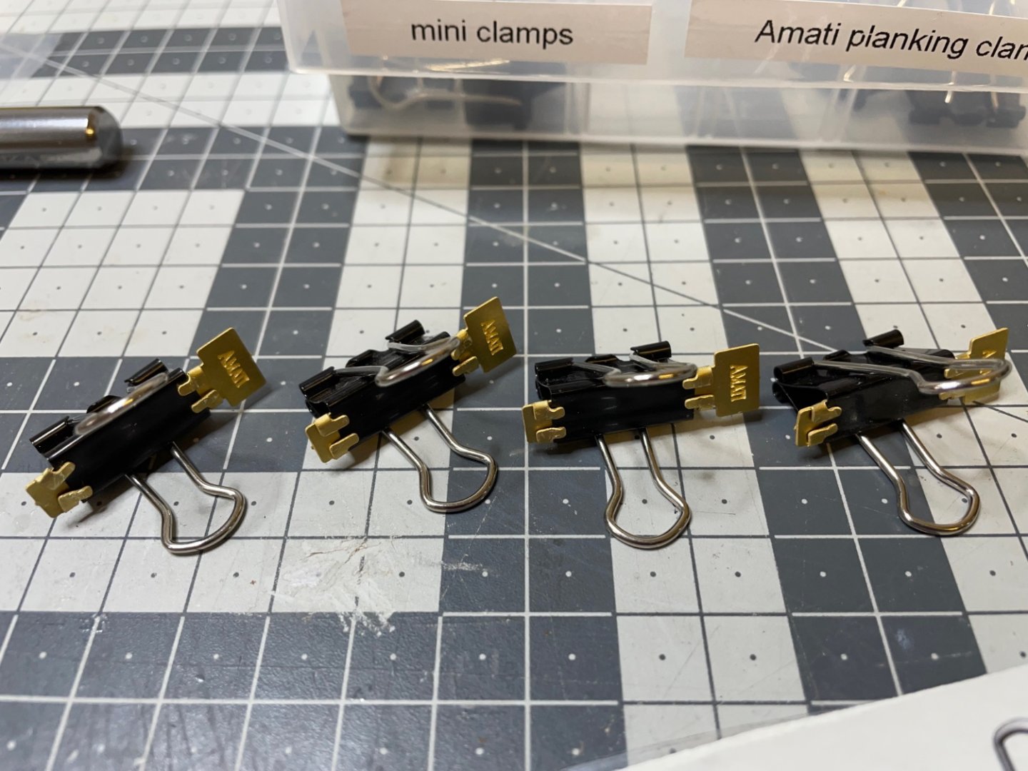
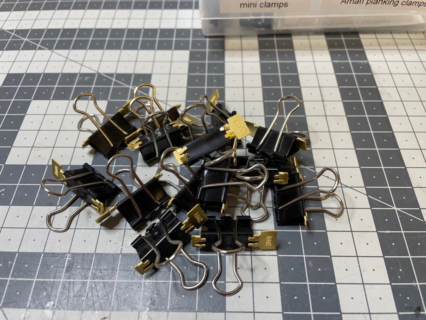
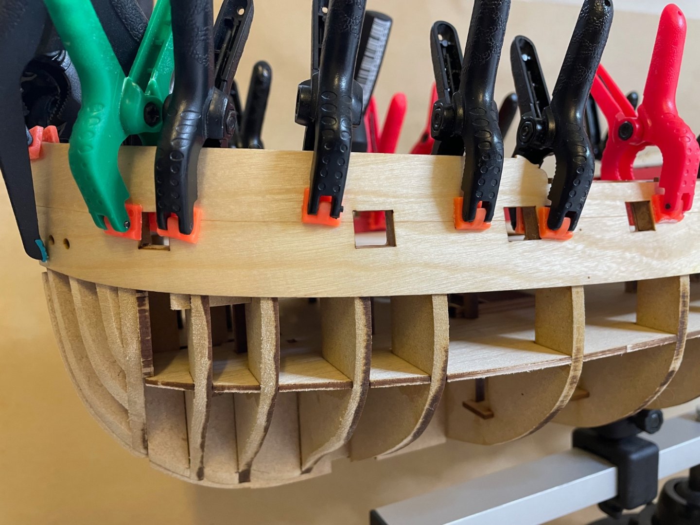
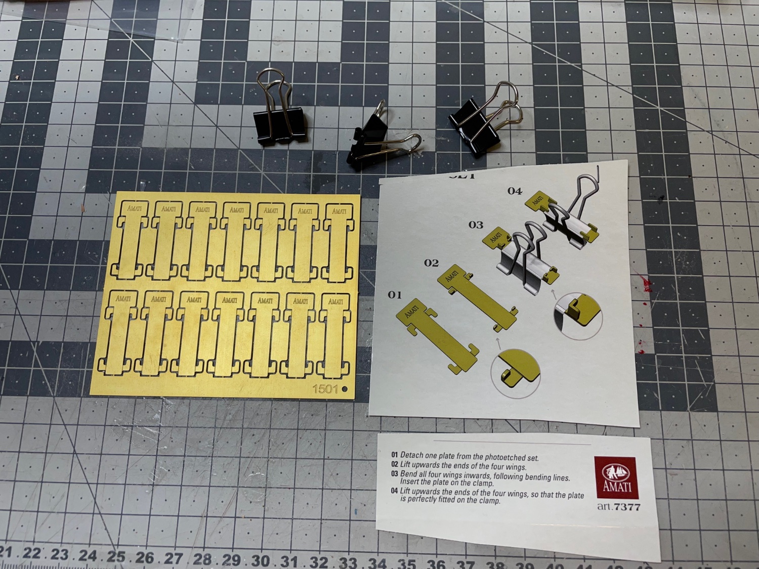
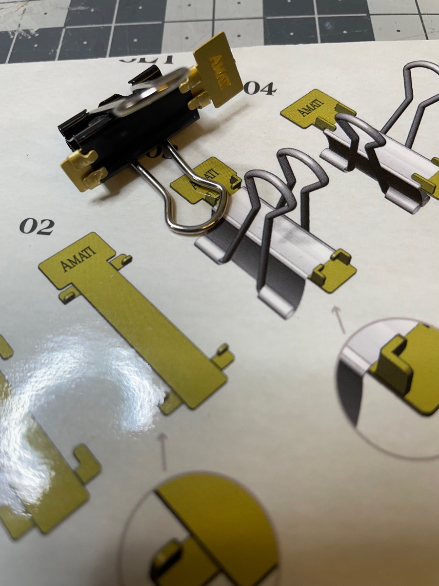
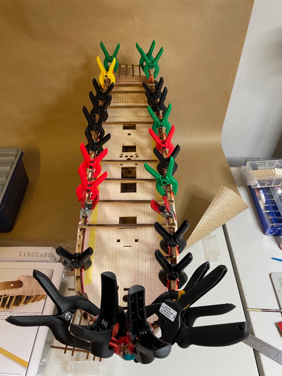
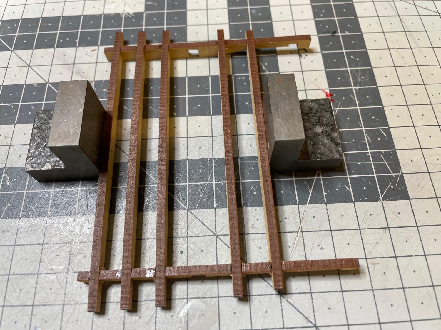
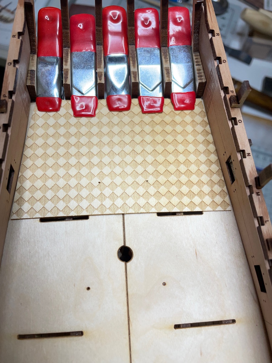
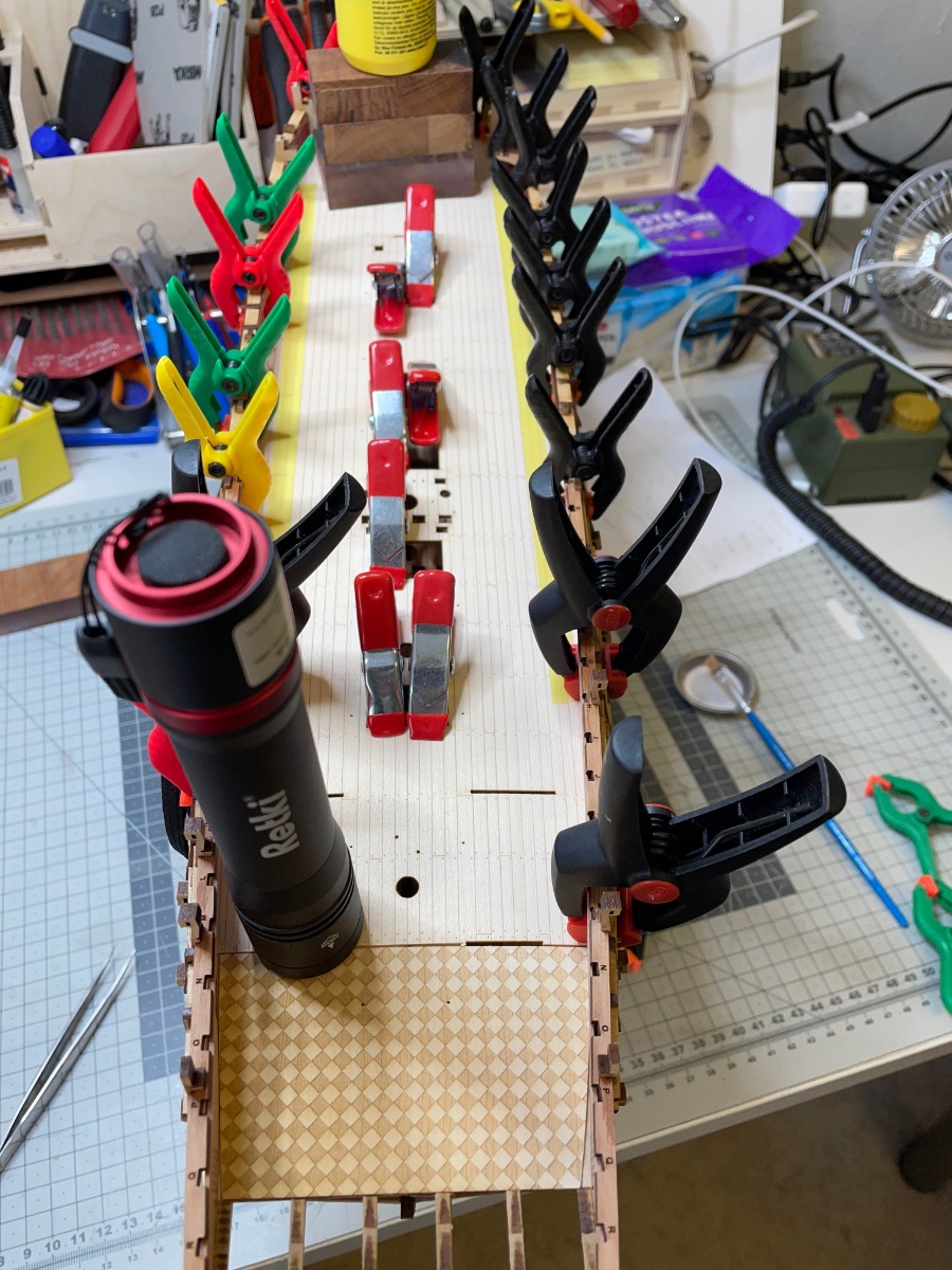
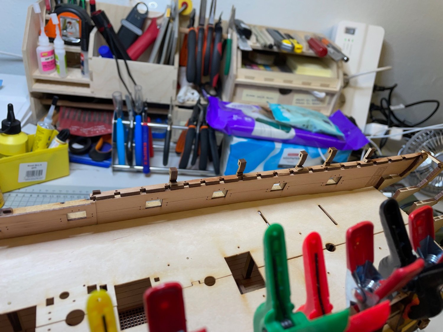
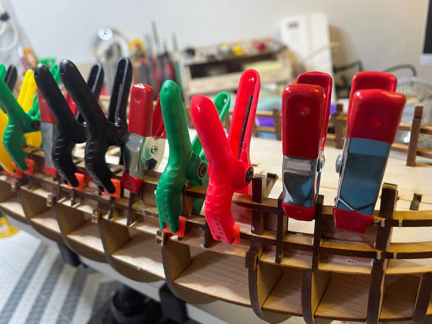
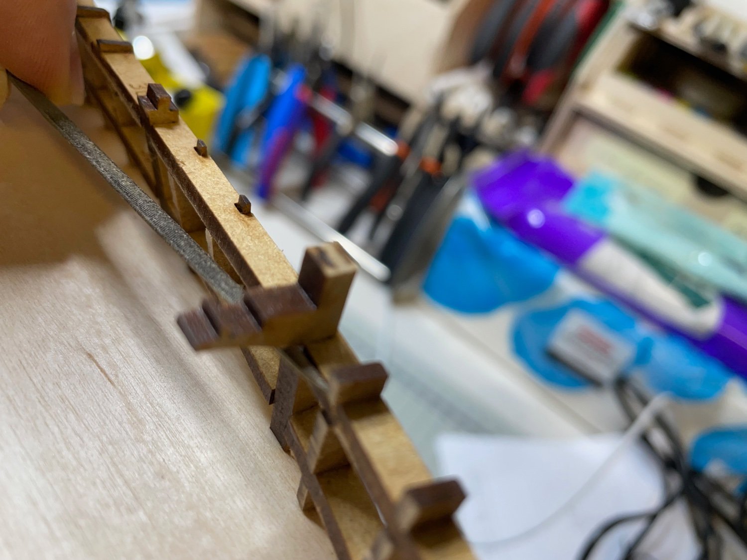
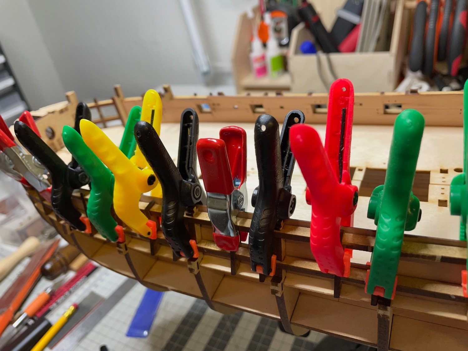
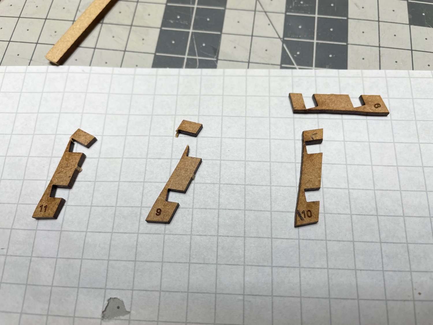
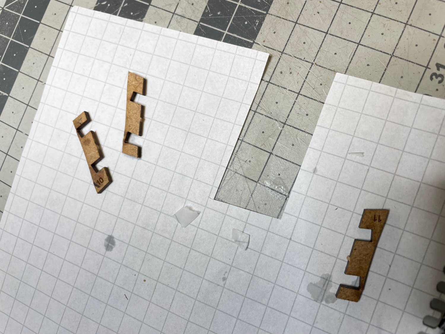
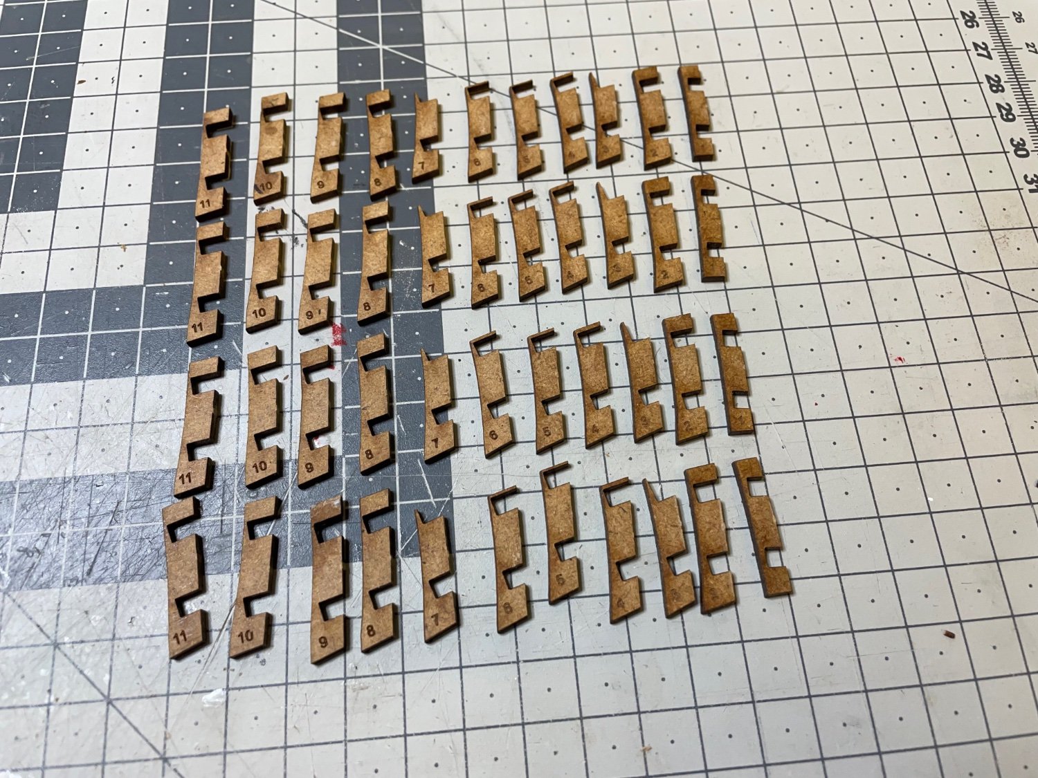
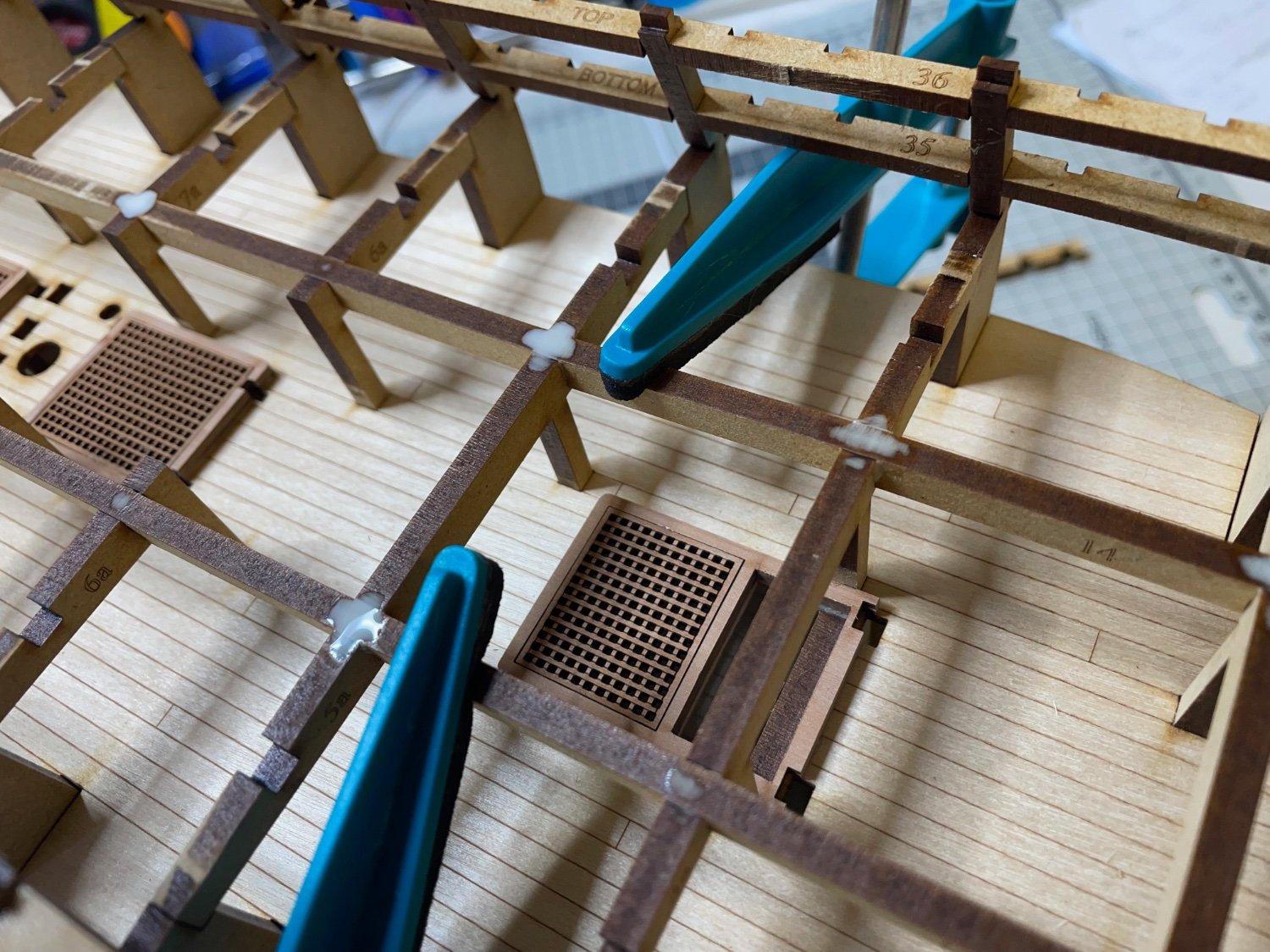
Photos 173-176: Well, while the glue is drying, I decided to get my hands on to these Amati planking clamps. I had bought them many years ago and had never used. I even forgot about them and when I saw them in Glenn's Sphinx build log, I thought I'll give them a try. It is a small project to prepare them:


-
BUILD DAY 12-13: 2 hours / Total: 22 hours
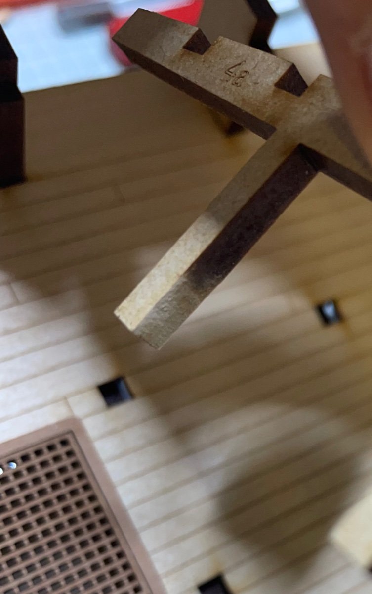
Photo 167: The parts dried enough overnight. This is one of them to show that the shape remains after removing.

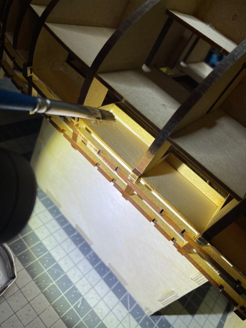
Photo 168: Brushing diluted wood glue, as recommended in the instructions. Here I mixed it with a bit less water, thus let it a bit thicker, compared to for example when I brushed in to the joints bulkheads, since in this case I don't need it to penetrate into any joints. This way it also won't run and leak. It is enough that it gives you time to make adjustments before it cures.

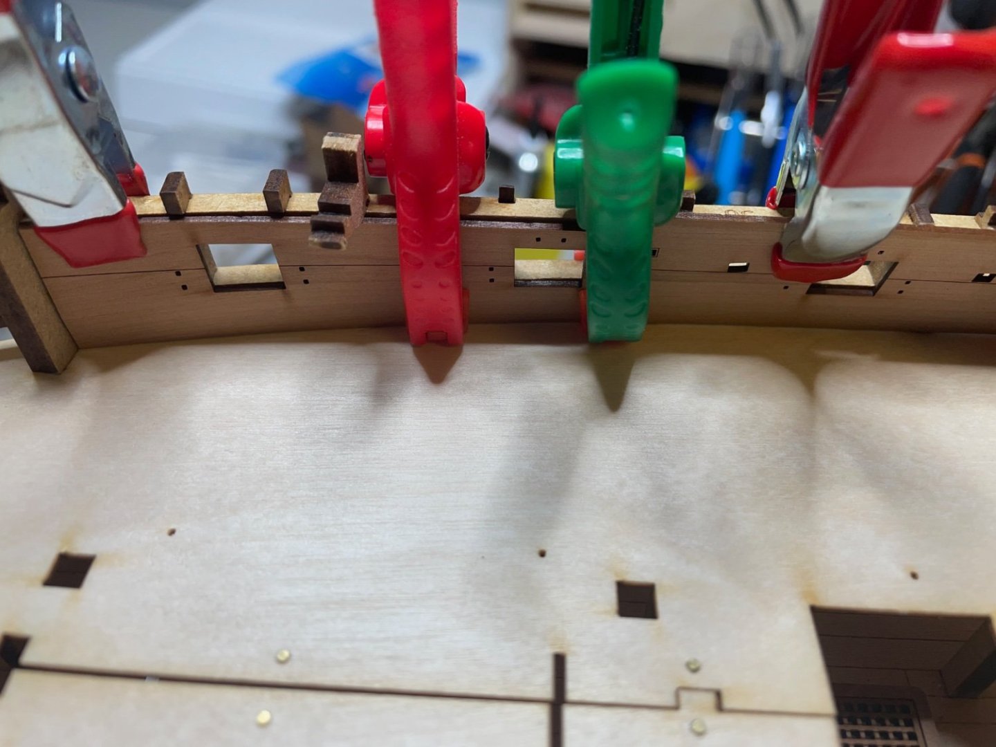
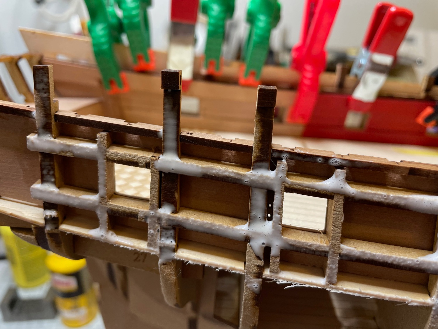
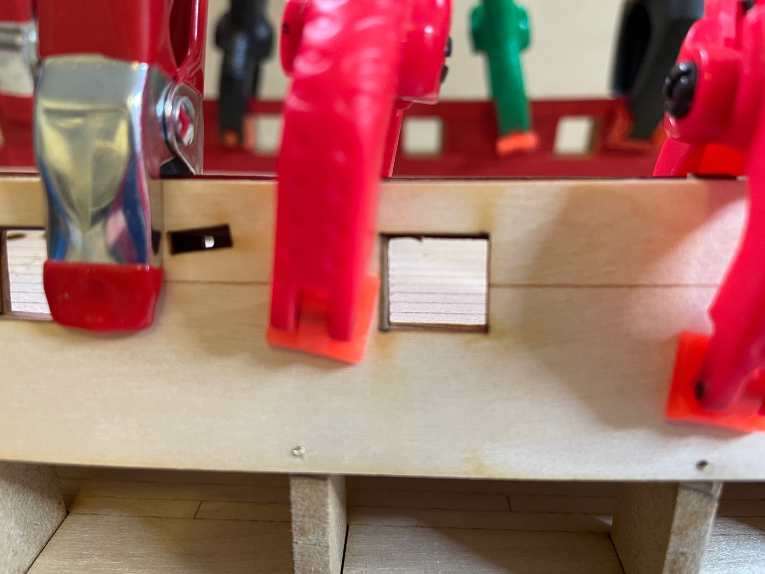
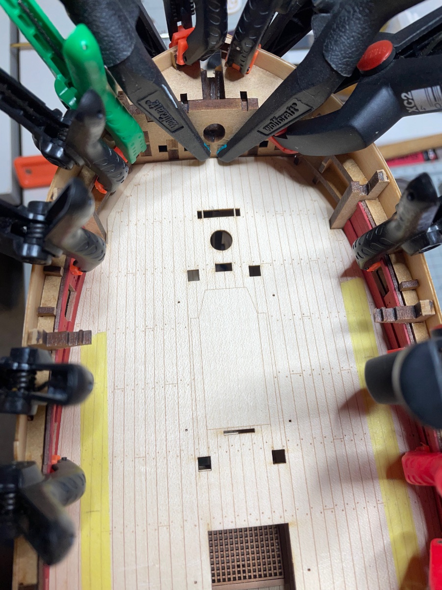
Photos 169-171: Carefully glued them in their positions. My main reference was to align the bow and then go on aligning with the gun port openings. You see in the last photo I used pins to ensure contact in a few spots where there was a gap at bottom edge with the bulkheads.
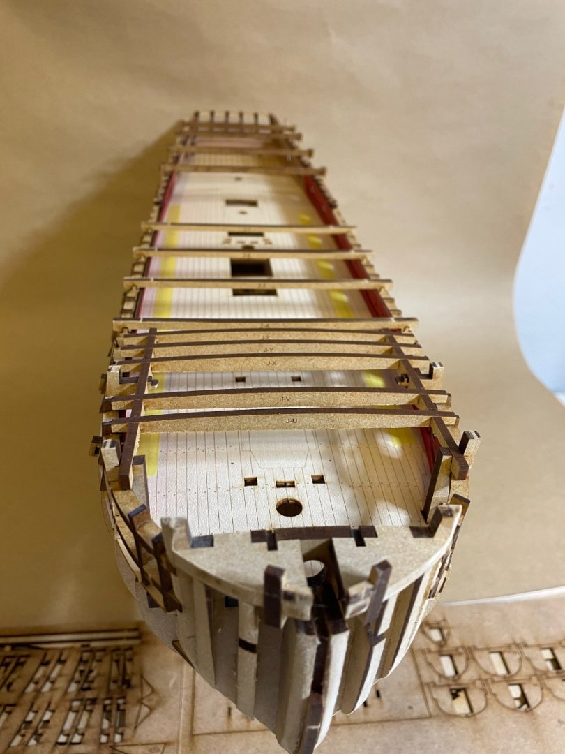
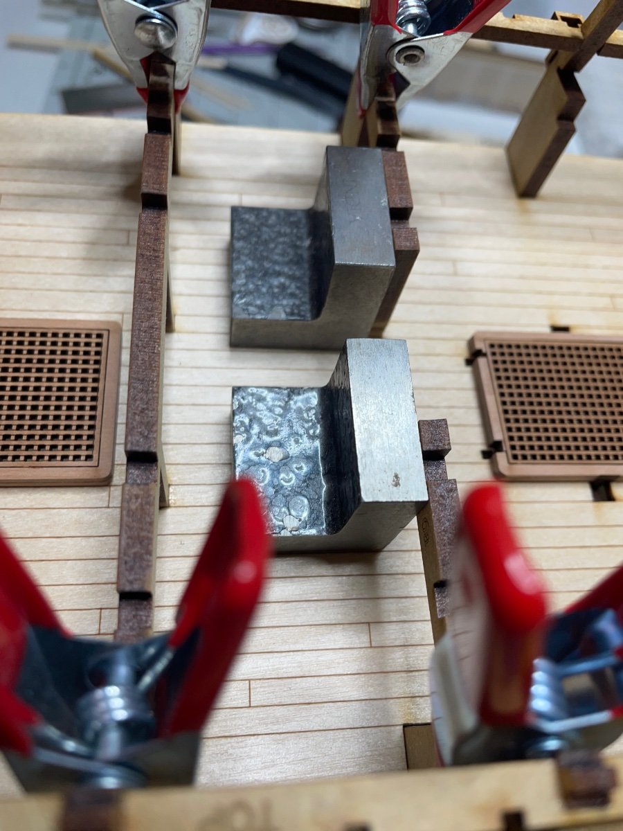
Photo 172: Waiting for the glue to dry. I am not starting planking today so I give them the whole overnight to dry properly. As you see I also placed the jigs into place, so the hull shape maintains correct while the glue dries. I wanted to do this because some bulkhead ears move slightly inwards/outwards when I use clamps. The jigs keep them in position.

-
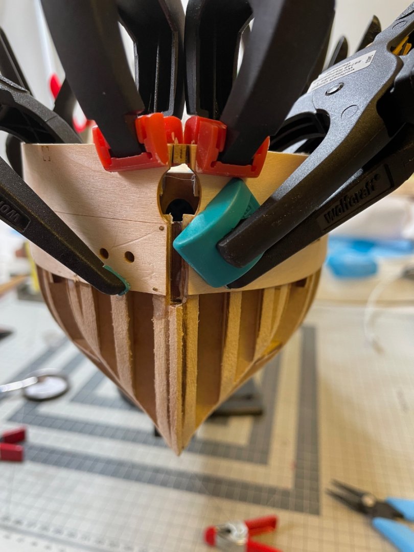
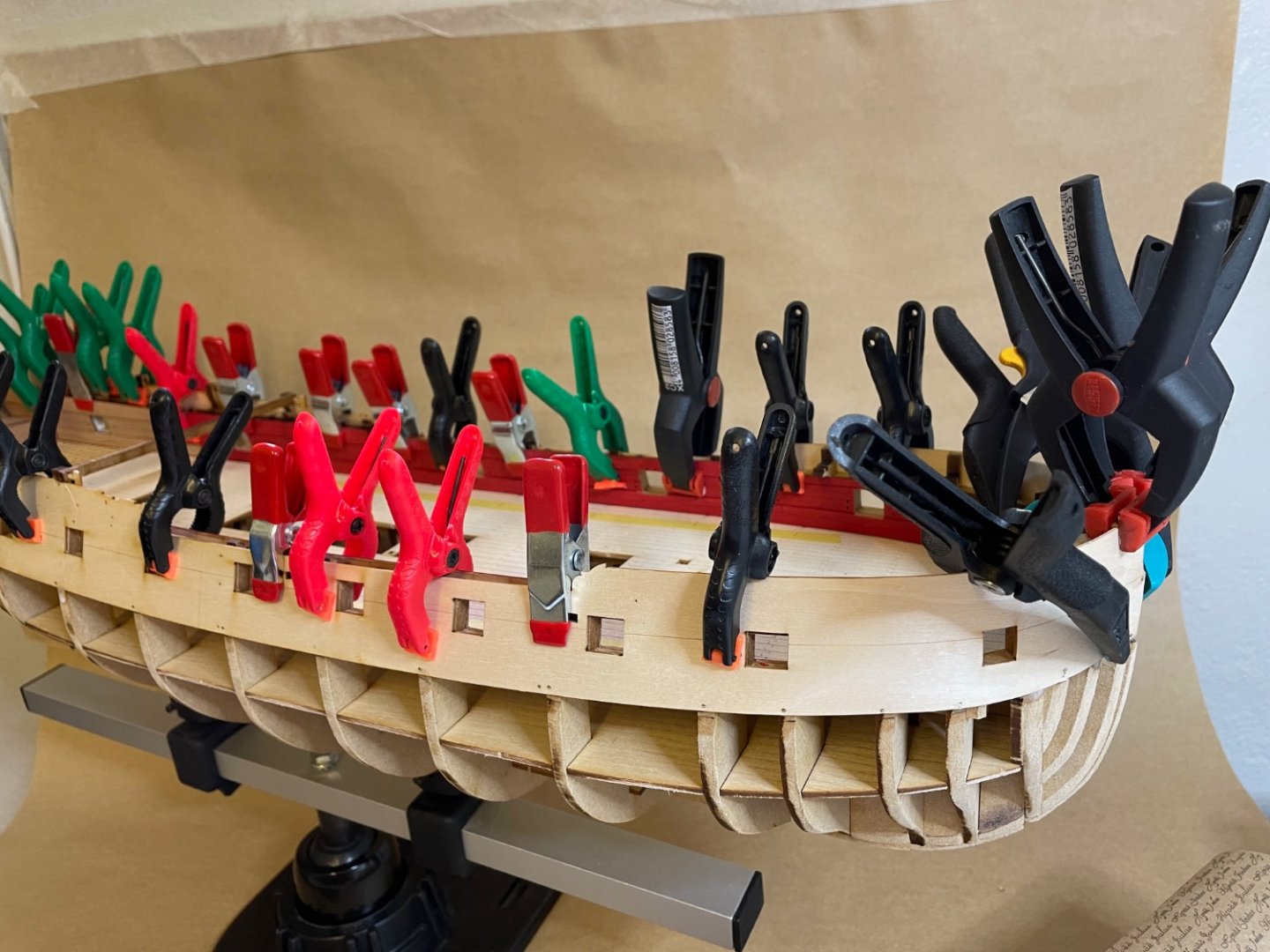
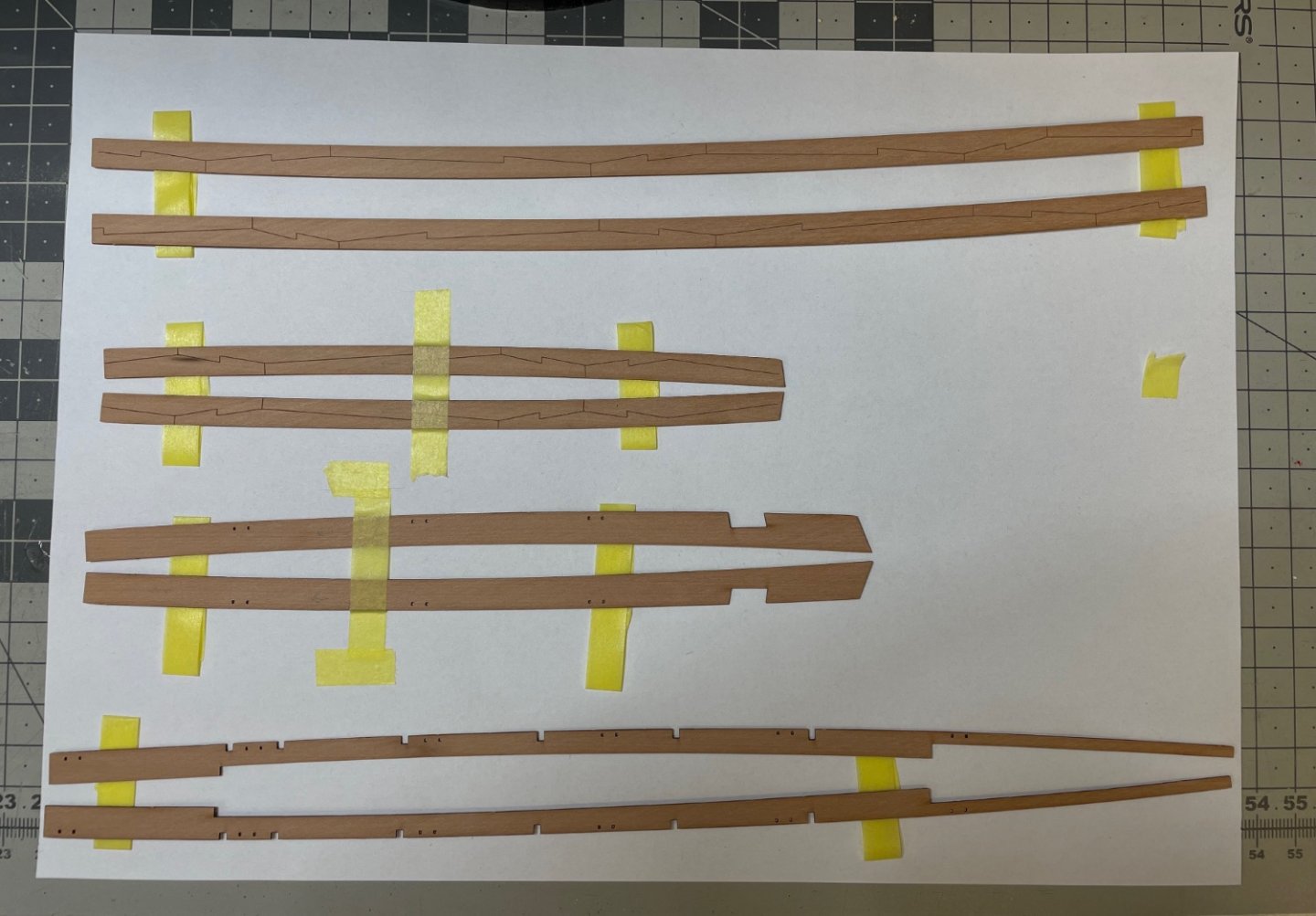
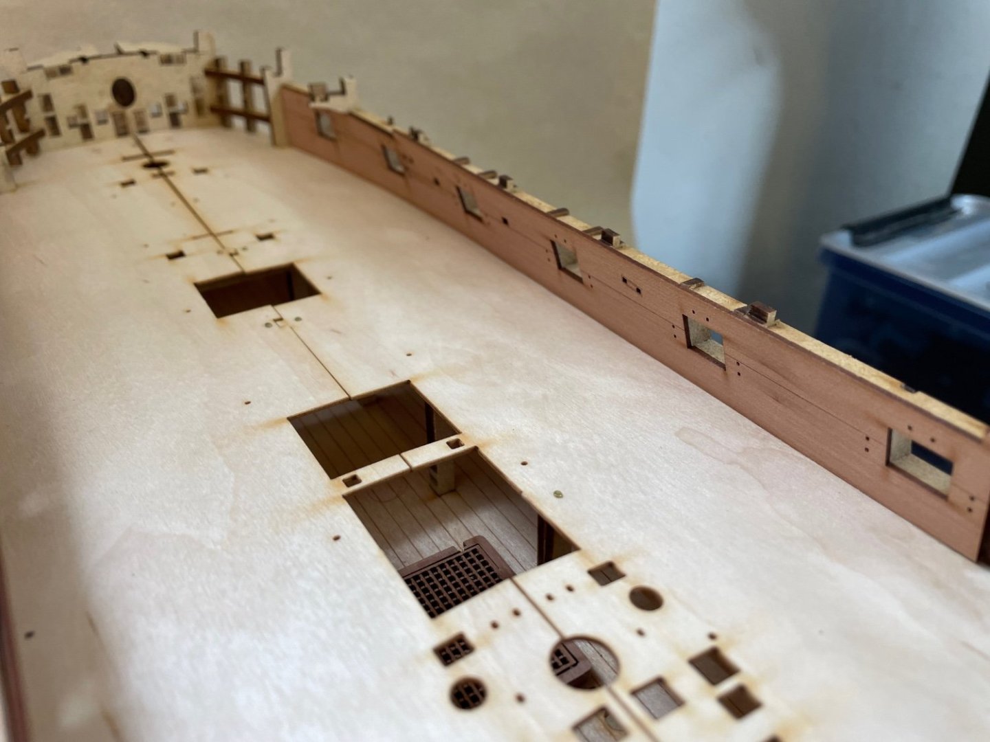
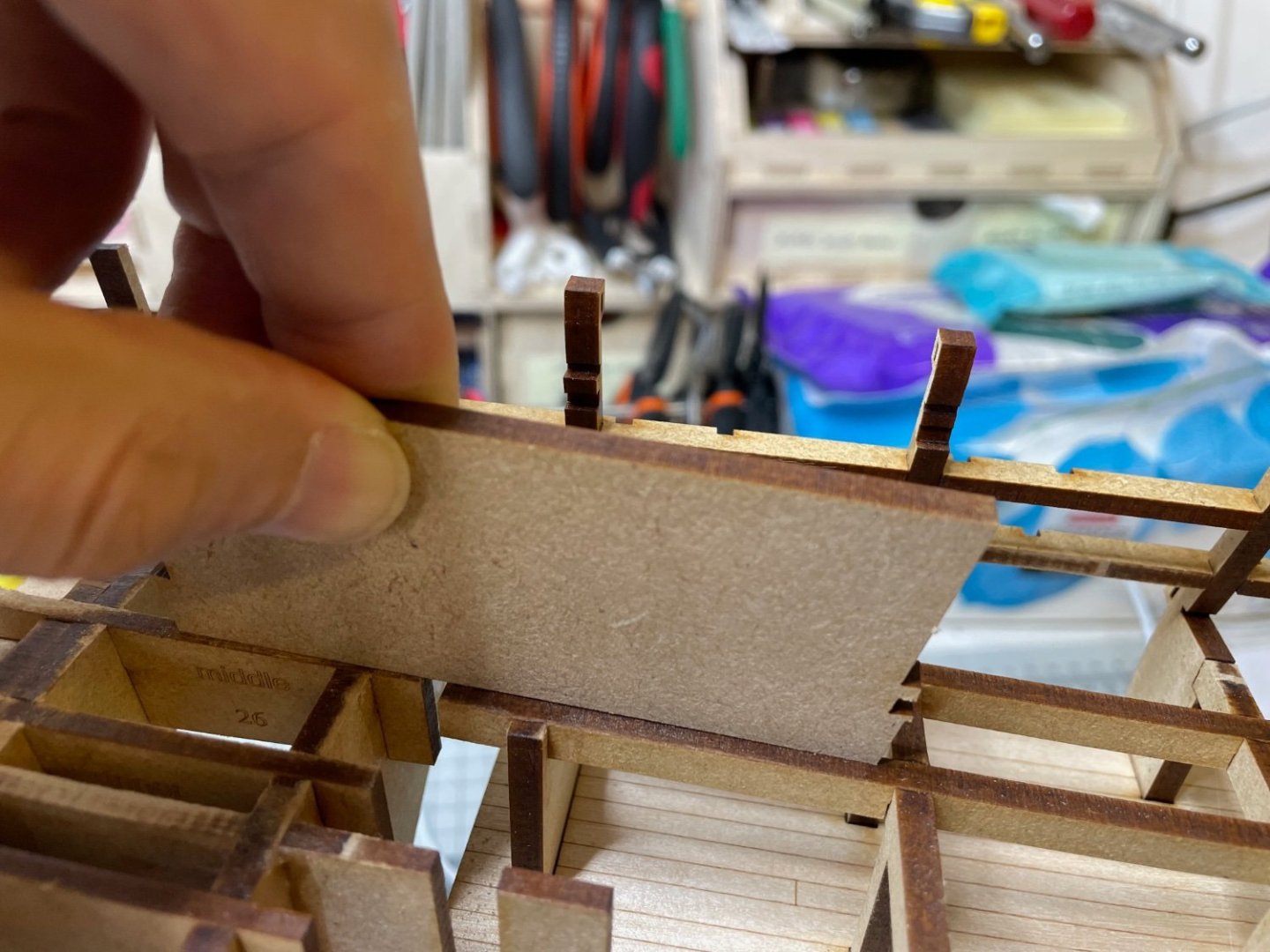
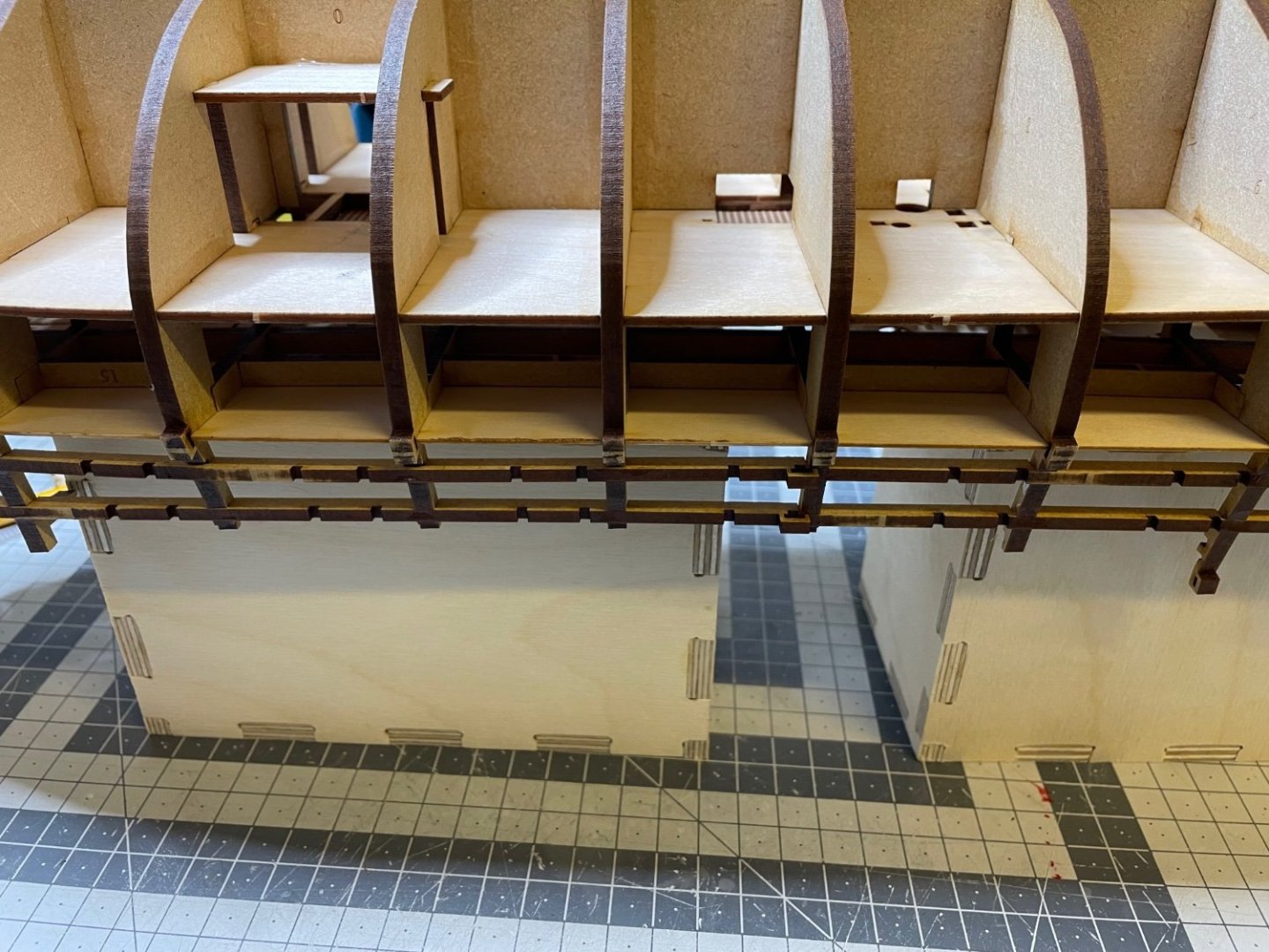
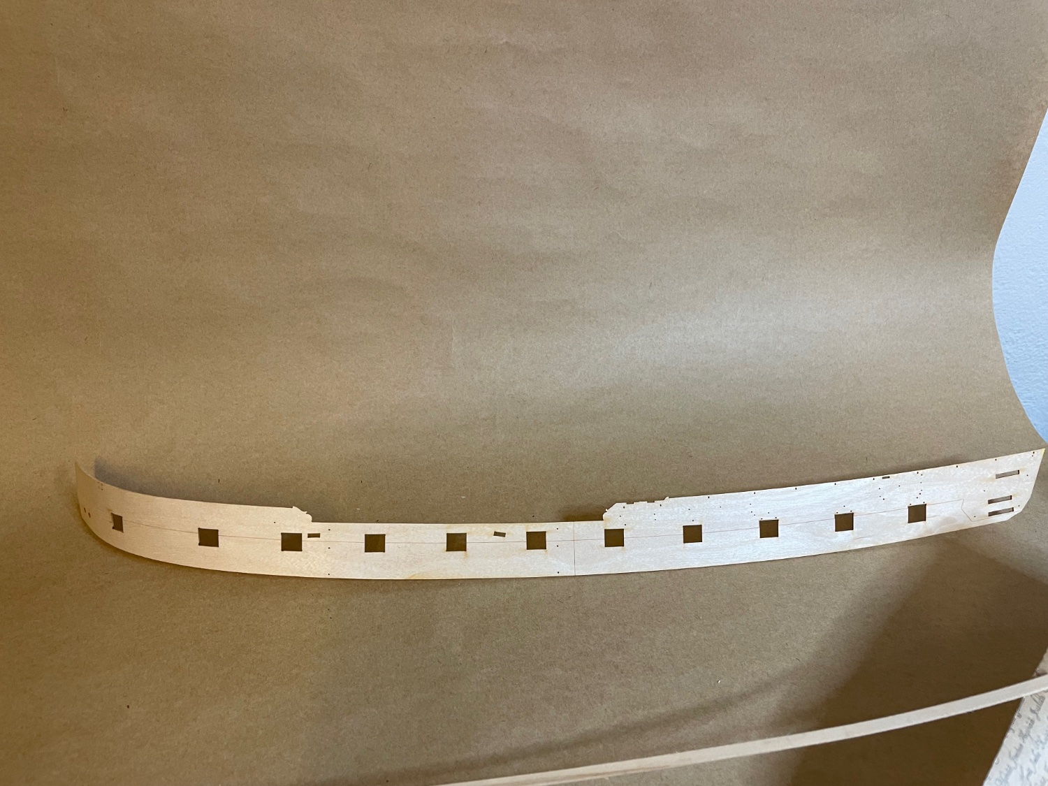
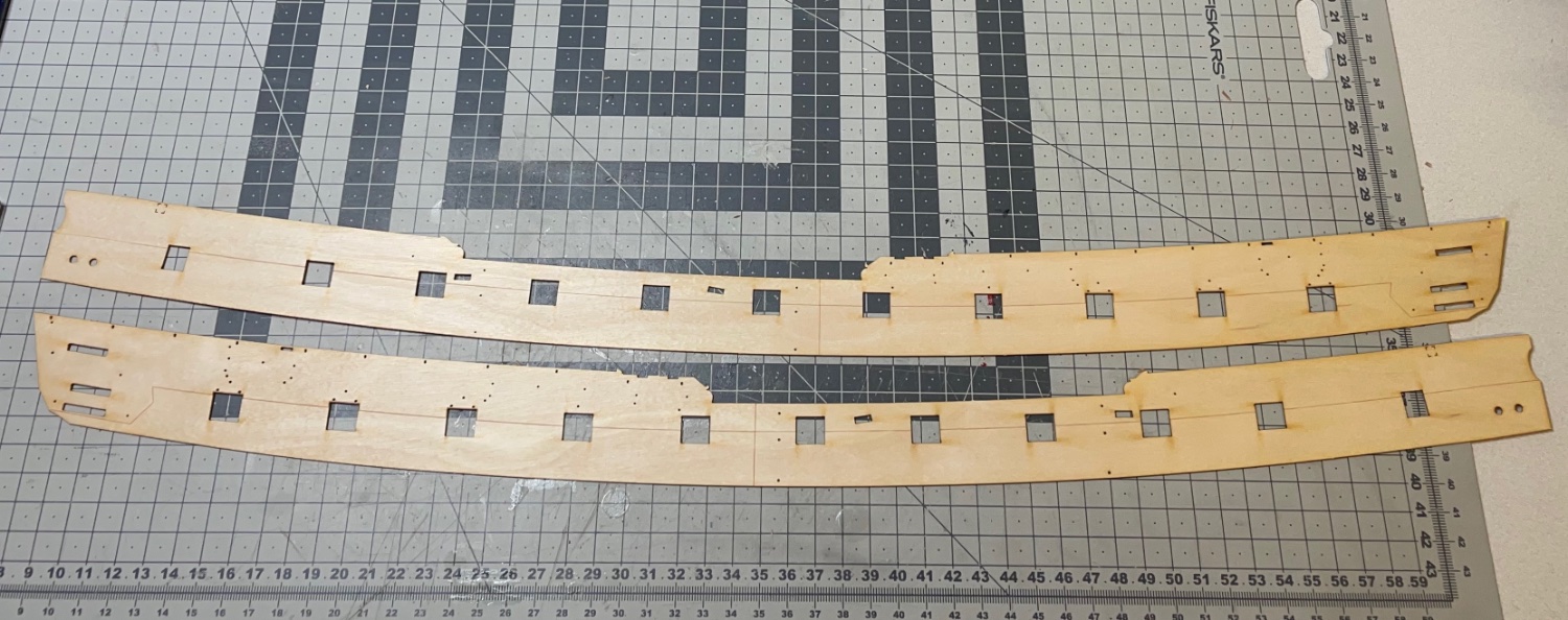
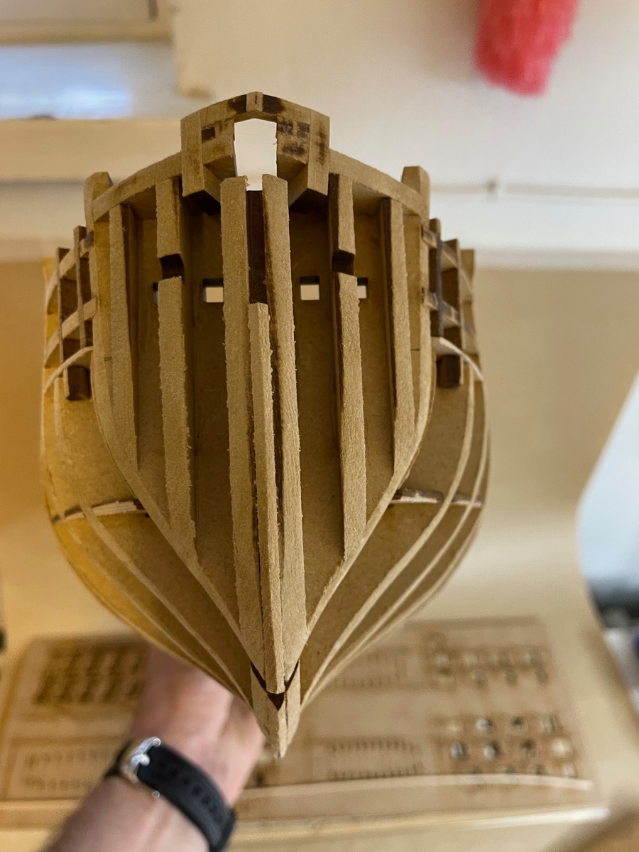
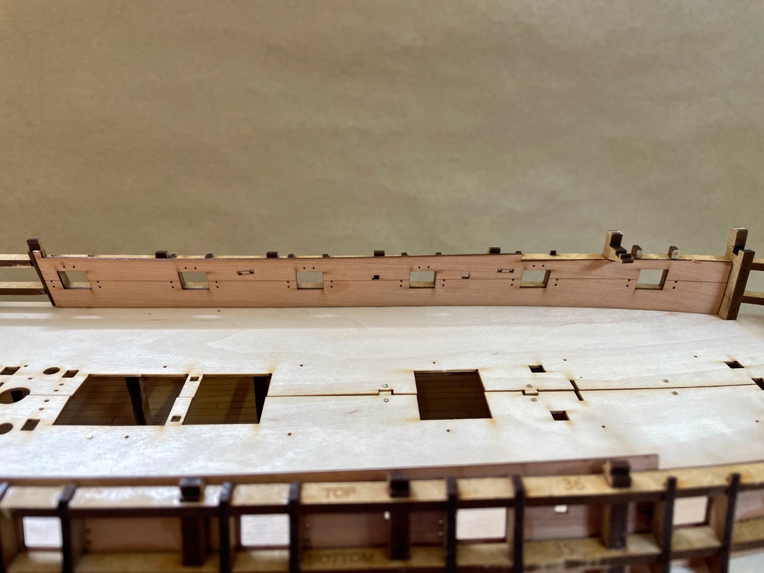
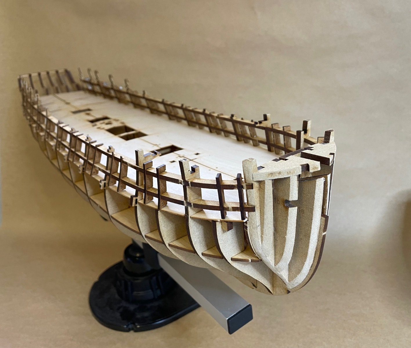
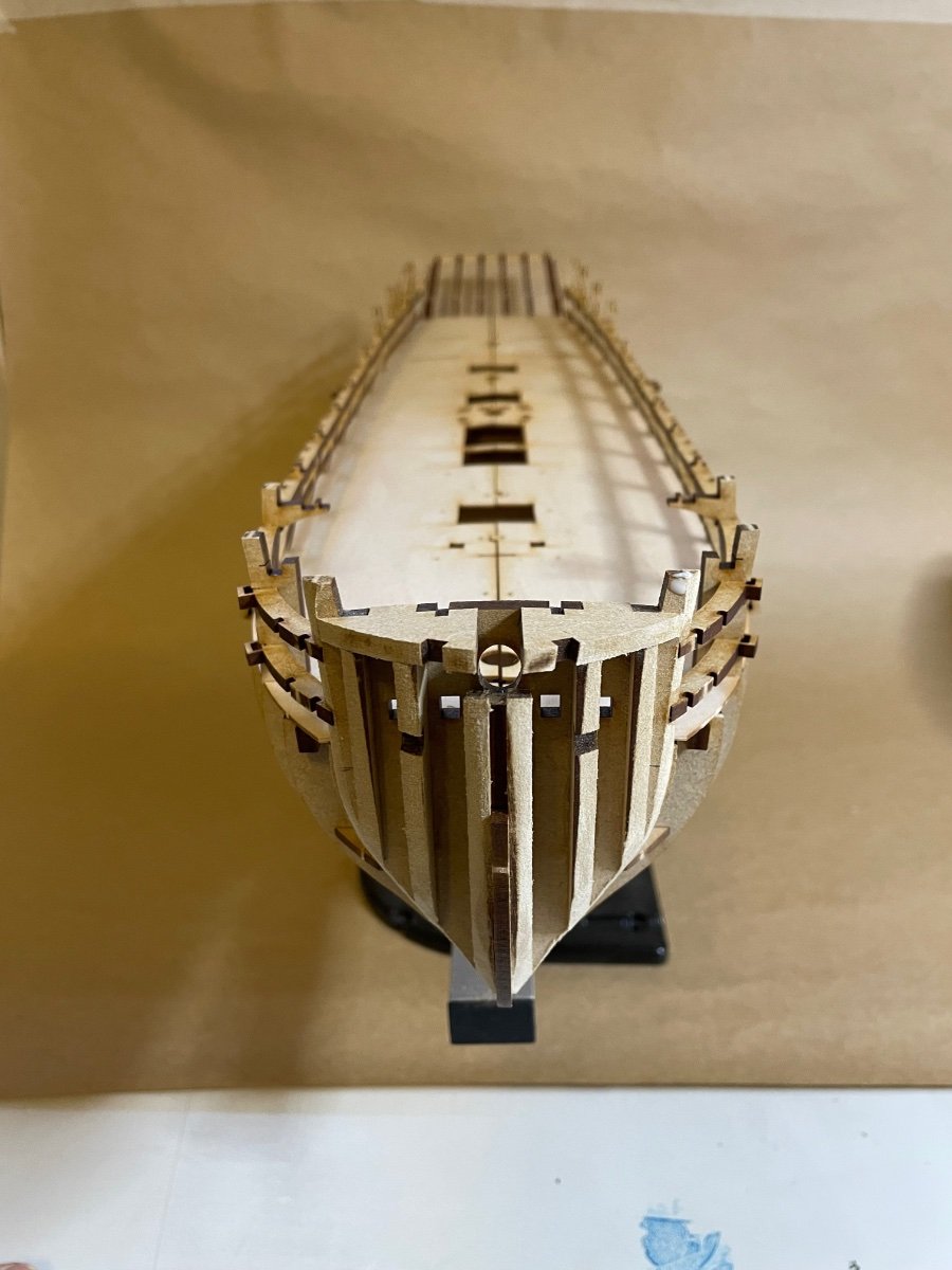
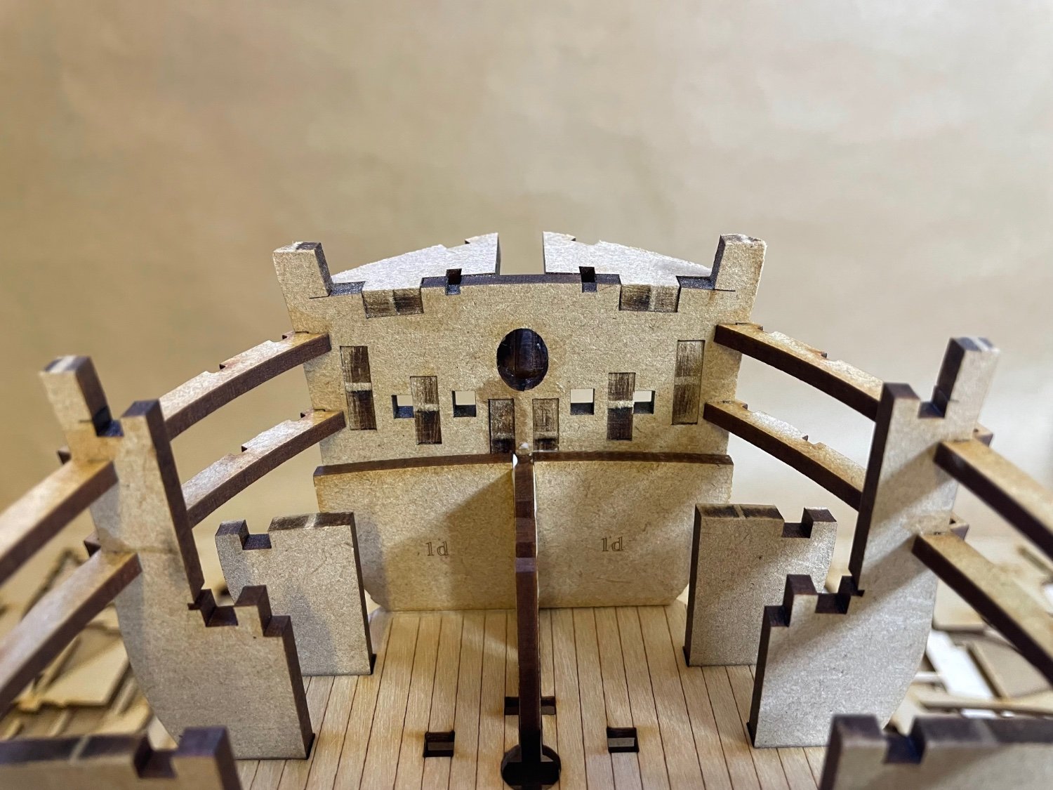
Photos 164-166: Upper Hull Side Patterns dry fit (or wet fit to be correct
") ) waiting to dry overnight. If you look at the photo taken from above, they fit almost airtight to the hull, making me overall satisfied with my hull construction... except for that little over-fairing at central keel at the prow discussed in my recent post.
) waiting to dry overnight. If you look at the photo taken from above, they fit almost airtight to the hull, making me overall satisfied with my hull construction... except for that little over-fairing at central keel at the prow discussed in my recent post.


- CiscoH, mtaylor, Oldsalt1950 and 2 others
-
 5
5
-
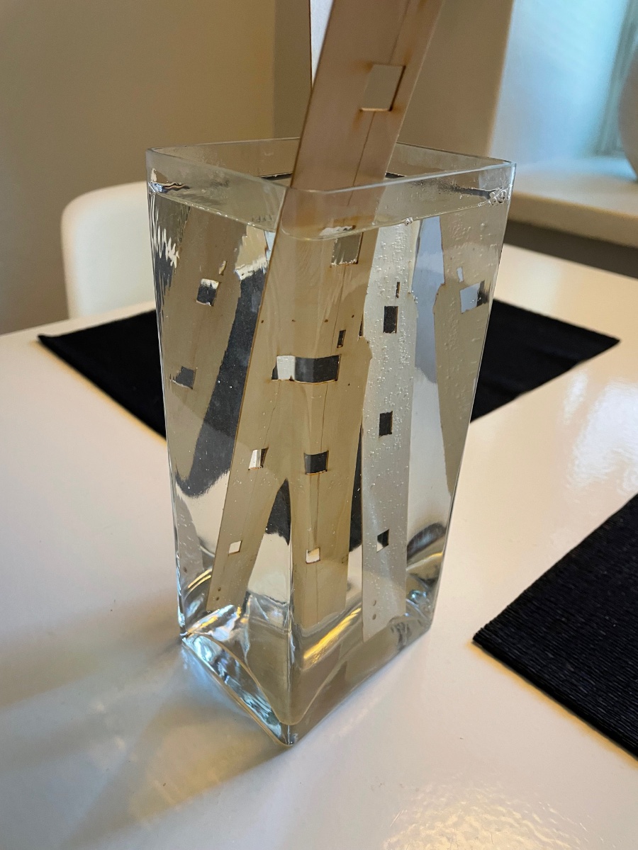
Photos 162-163: In the mean time the Upper Hull Side Patterns are being soaked in hot water in a flower vase deep enough I found at home.


- Oldsalt1950, mtaylor, CiscoH and 1 other
-
4
-
Build day 12: 1 hour / Total: 21 hours
Thank you Chris for this short chat and I finally decided to trim the openings. Overall I used the x-acto and two different sizes of files, it went quite alright for the total of 20 gun ports. It took about an hour in total, at a few minutes per opening.
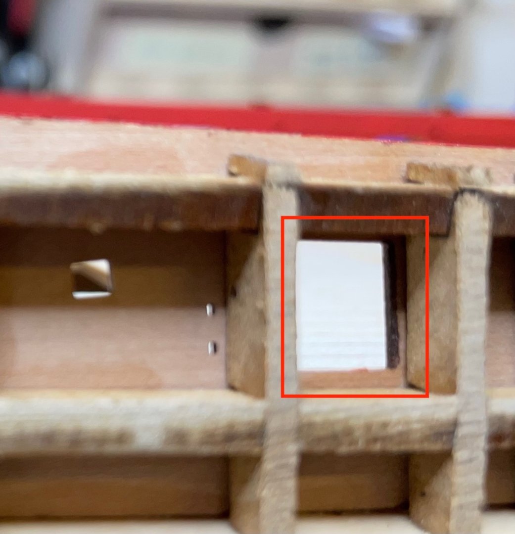
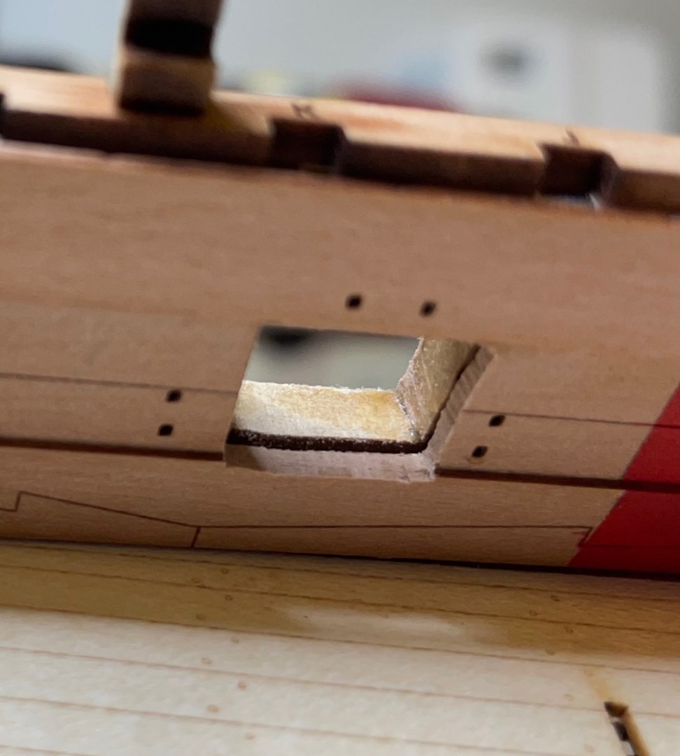
Photos 159-161: Here are some before and after photos, they do not necessarily belong the same gun port opening.

- BenD, Oldsalt1950, DonSangria and 2 others
-
5
-
3 minutes ago, chris watton said:
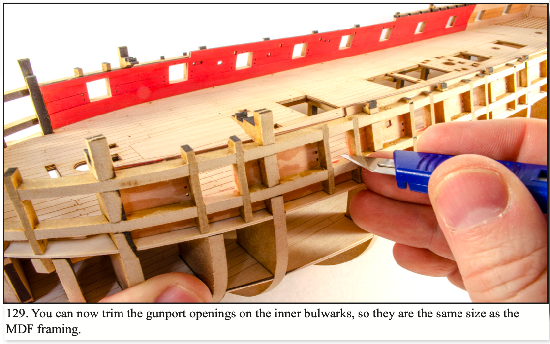
The gun ports are not exactly square shaped, they will need cutting/filing to the same size as the MDF frames for the gun ports. You have the gun port opening and shape ready made, I do not know why you think you would mess it up?
Well, OK not a mathematical square but I meant that when I look at the gunport openings on the inner bulwarks from the deck side, they are perfectly laser cut and identical looking, though I understand that those cuts are made smaller than normal, to be trimmed later to the size of the MDF frames. I was just wondering if I would avoid trimming them from outside with a knife, would it cause a problem during construction later, other than visual. Maybe I am just being lazy.
-
A question one step before planking: How necessary is it to trim the gun port openings to same size as the MDF frames? Is it only for visual historical accuracy or will it be crucial to fit something later? I am just concerned I can't get perfect identical square shapes when viewed from the deck side and I don't want them to look worse than they are at the moment.
-
31 minutes ago, James H said:
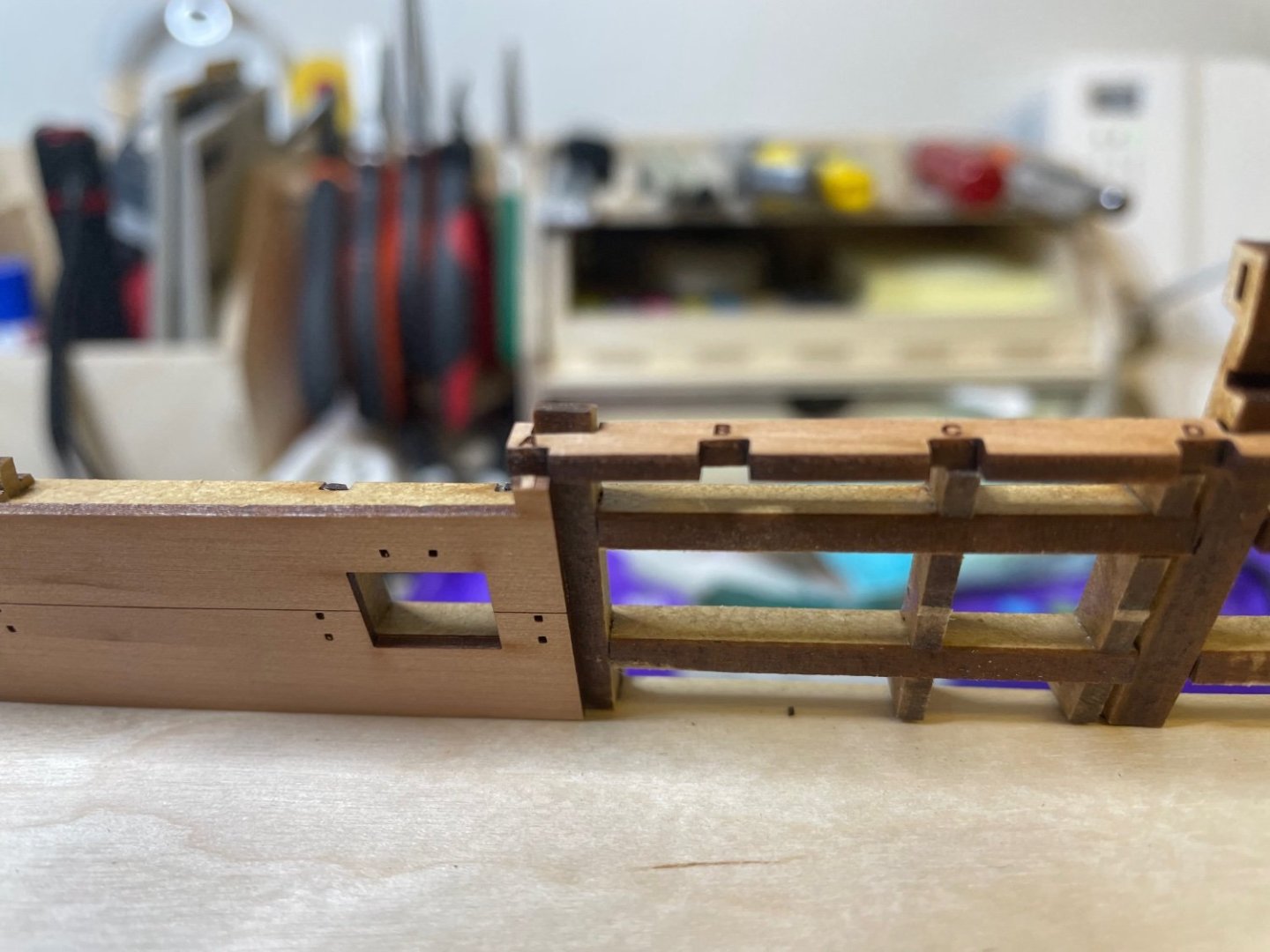
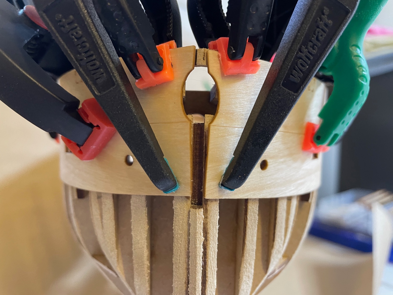
You can probably plank right to the front, over that MDF so that the planks come to a 'point'.
From there, you can sand this back, flattening off that 'point' until you have the maximum joint area when the pear prow is slotted into place.Thanks for the advice. I will follow that. I think I can manage.
- Mr Whippy, mtaylor, Oldsalt1950 and 1 other
-
4
-
12 minutes ago, James H said:
I'm a little concerned that you've sanded the MDF central keel to a point at the prow and going around the underside. That should've been a flat face which is part of there the prow glues. The planks would've butted up to the side of in and been sanded, leaving that flat face for a glue surface.
I have no idea why I did it like that 🤨. I think I somehow thought of my earlier builds where the planks from each side meet at the front and are glued to to each other. Damn. In your photo it is obvious that the central keel should be left as it is. I should have followed the photos more carefully.
What do you suggest I do now? Sand it totally flush, cut a similar piece from a scrap MDF and glue it there? Or will I have still a chance to rectify it when I glue the prow pattern?
- mtaylor and Oldsalt1950
-
2
-
BUILD DAY 11: 2 hours / Total: 20 hours
It was a great sunny day today here, I took the opportunity to hull fairing outside in the yard.
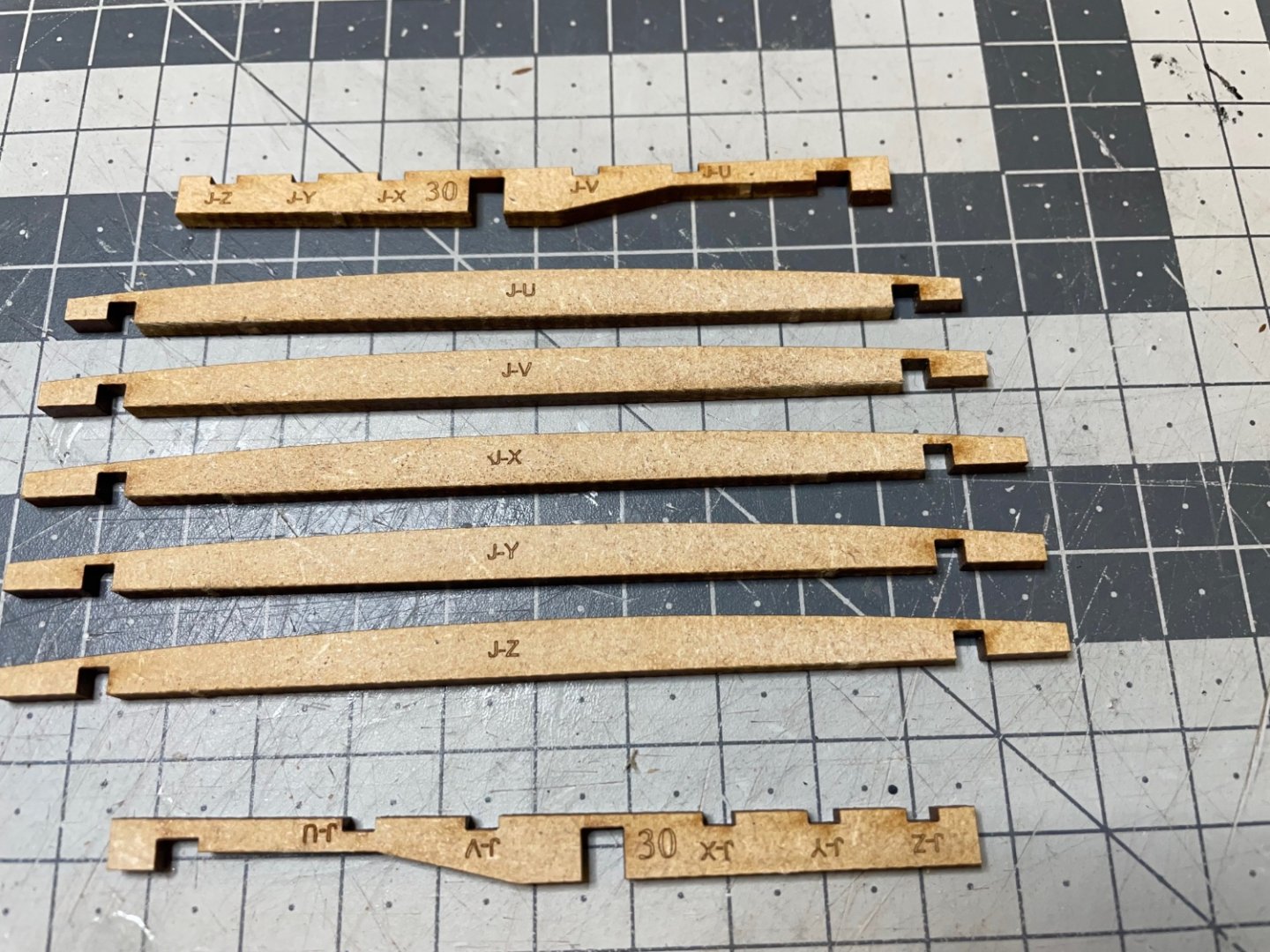
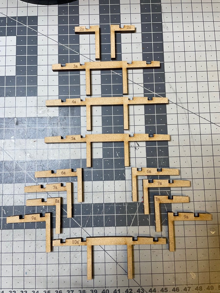
Before that I built the jigs. These are designed to maintain the width between bulwarks whilst adding external faces and planks etc. First time I have ever seen these in any model I built before and that's another proof of how well this kit has been designed to help the builder minimize errors during construction. 💯
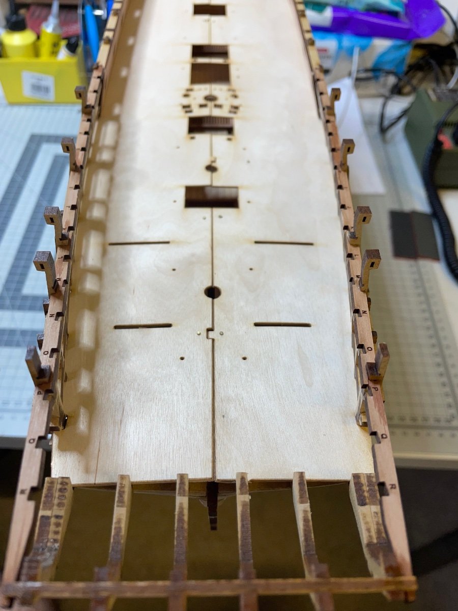
Photos 153-155: Jigs carefully glued and temporarily placed in their positions. You do not glue them to hull.

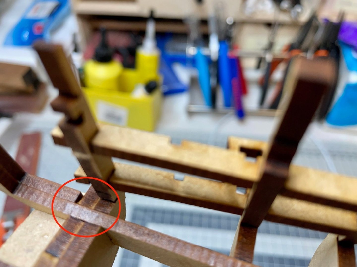
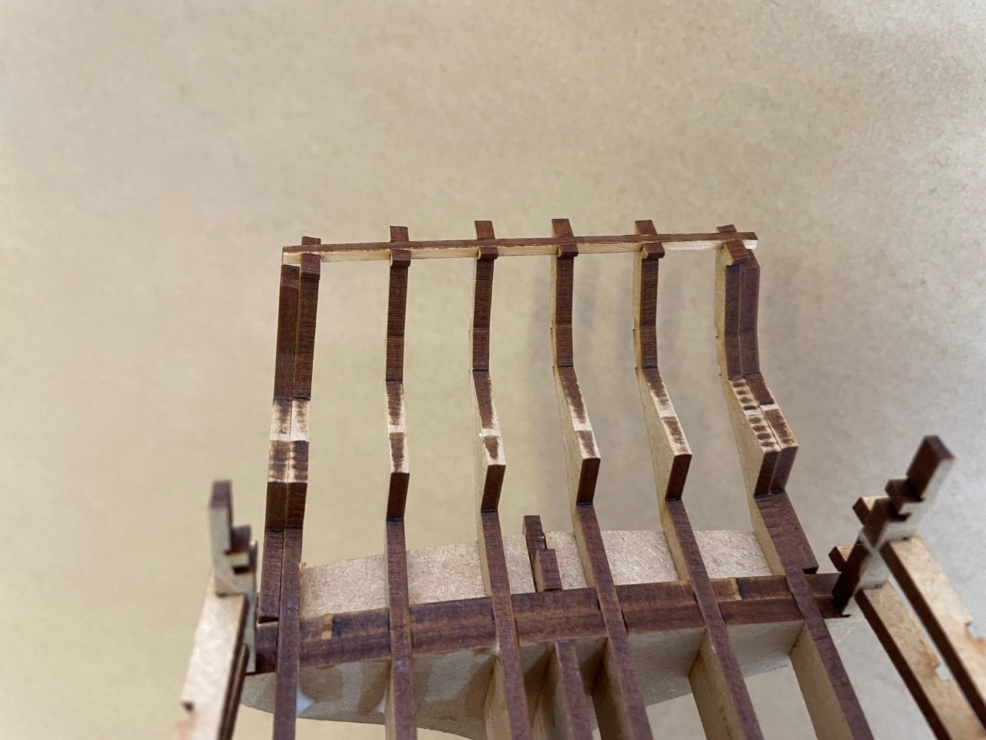
Photos 156-157: Two shots showing bow and stern after sanding. Sanding took about an hour. I tested with a planking strip on the way and paid attention that both sides are symmetrical. I can't say it is perfect, but mainly looking precise enough. I can make small sanding adjustments in individual spots during actual planking if need be.

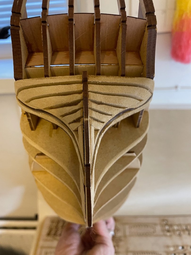
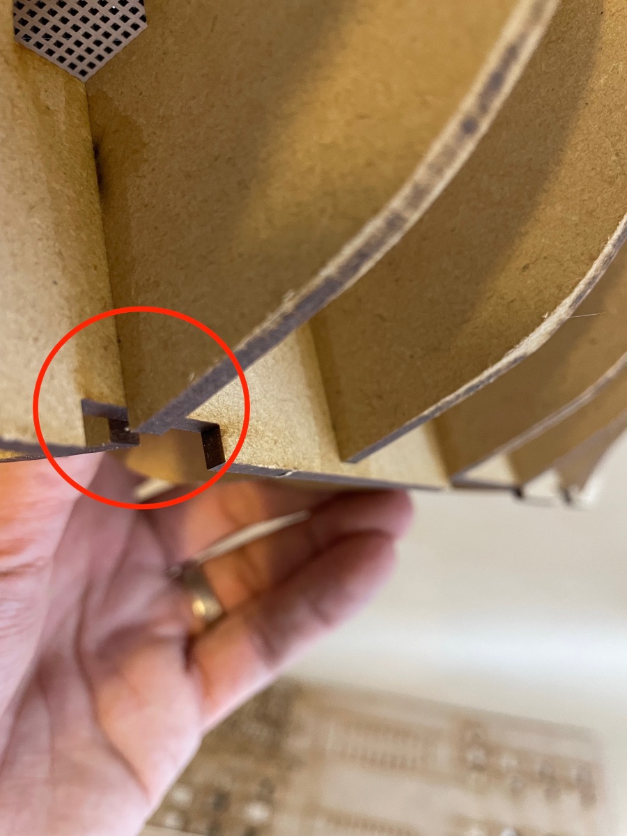
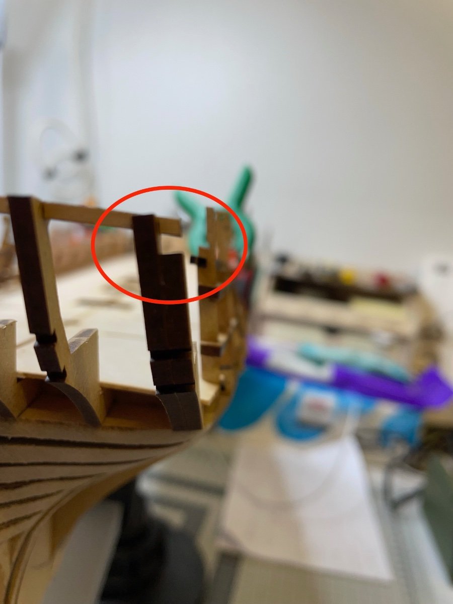
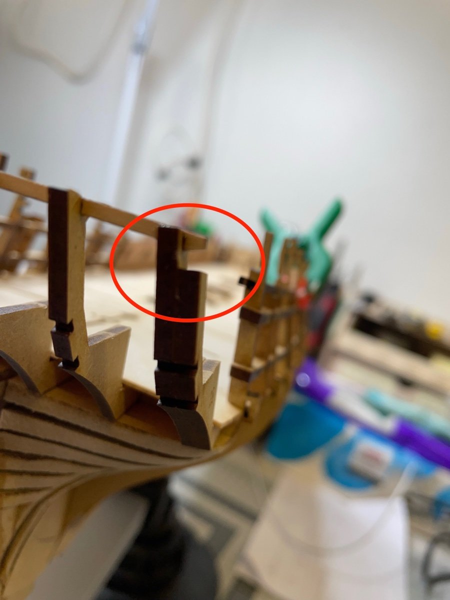
Photo 158: I didn't touch here... yet. I am sure there is a reason the bulkhead extends below that notch. Future steps will show what to do with it.

- mtaylor and chris watton
-
2
-
BUILD DAY 10: 4 hours / Total: 18 hours
In this slightly longer build day I went through Gun Deck Pattern, Checker Pattern, bulwarks painting, Lower Spirketting, Deck Clamp Patterns, Stern Cabin Bulkhead Pattern and the Stern Cabin Seat Pattern installations.
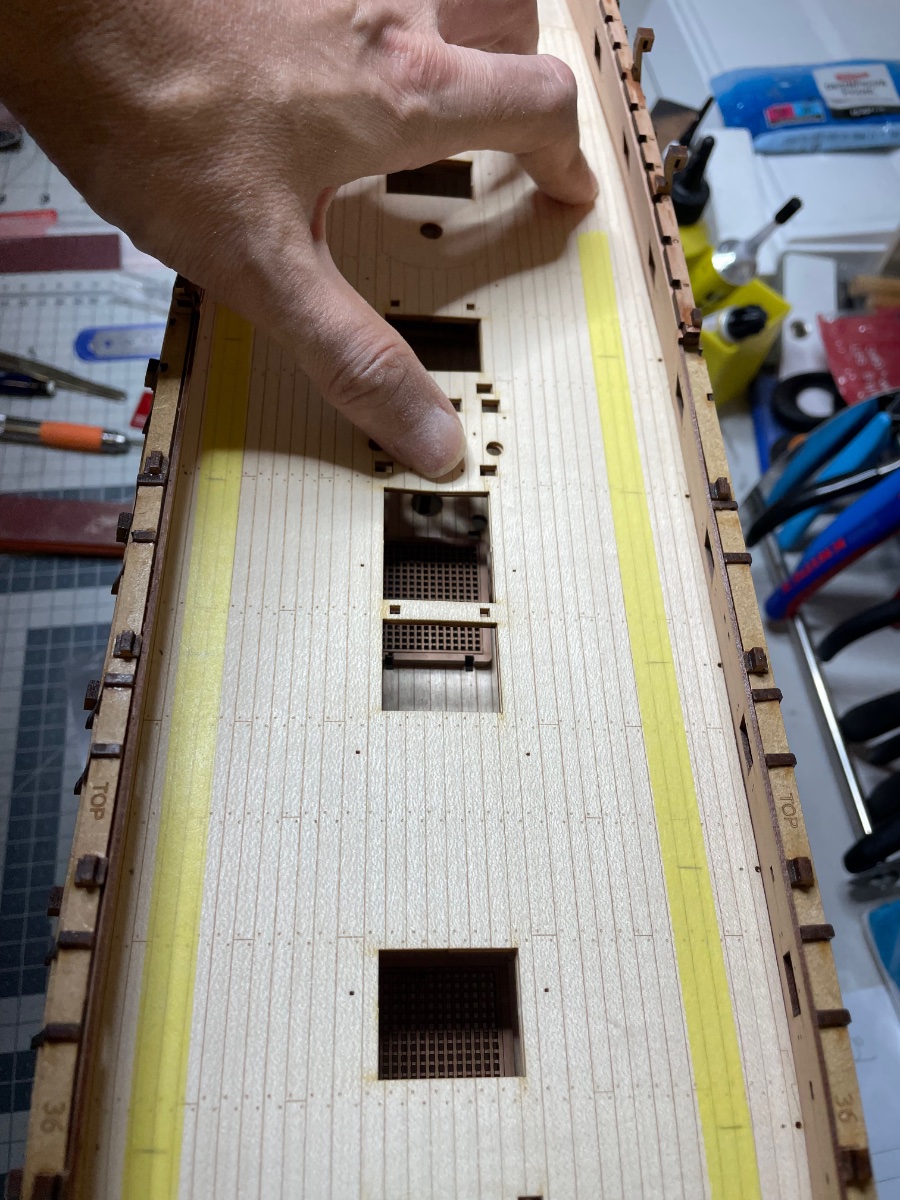
Photo 141: As it is, Gun Deck Pattern forms a bow on my model and therefore needs trimming from the edges in order to fit firmly. This is also instructed so in the manual as an expected situation.
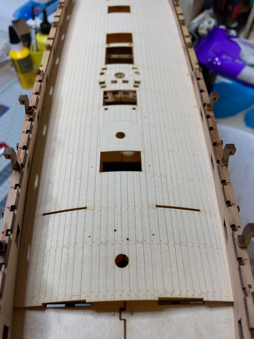
Photo 142: After several rounds of sanding and trimming I finally fit it in place. But you see the small sequence of holes close to the edge are almost already at the edge. It makes me wonder if I didn't install the Inner Bulwark Gundeck Patterns with full contact to the bulkheads, thereby narrowing the width. But they look alright. Though I don't worry too much, as the deviation is only about 1mm at worst. If I guess right those holes will probably be used for rigging. I marked across their locations on a masking tape as seen in the photo, in case I need to know later.
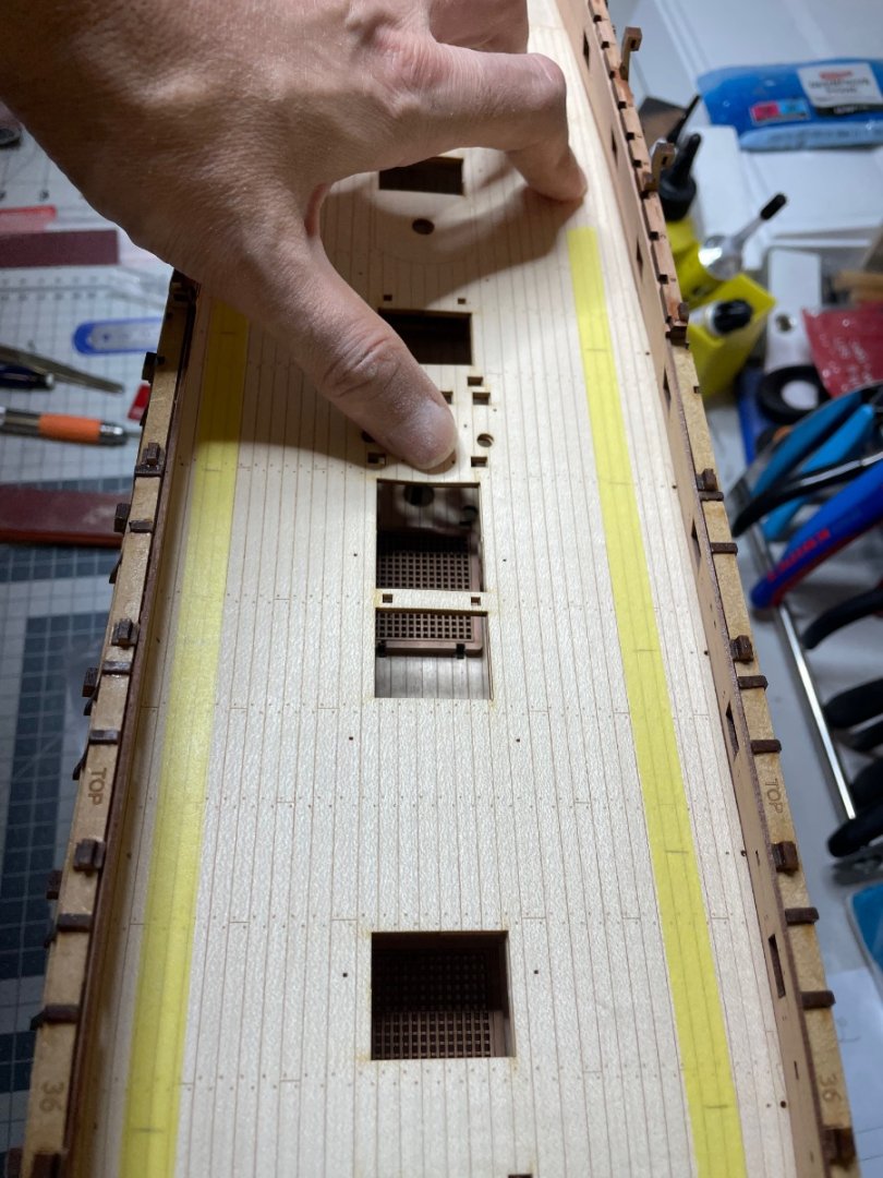
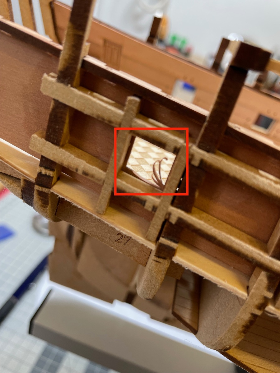
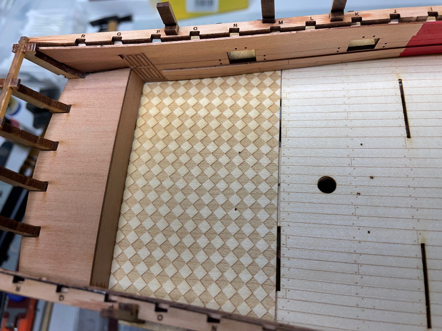
Photo 143: Checker Pattern dry fit in place after slight sanding.
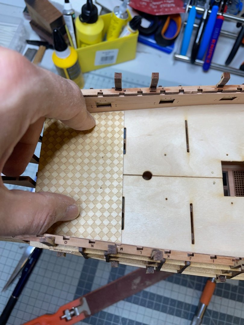
Photo 144: Marked the red paint border.
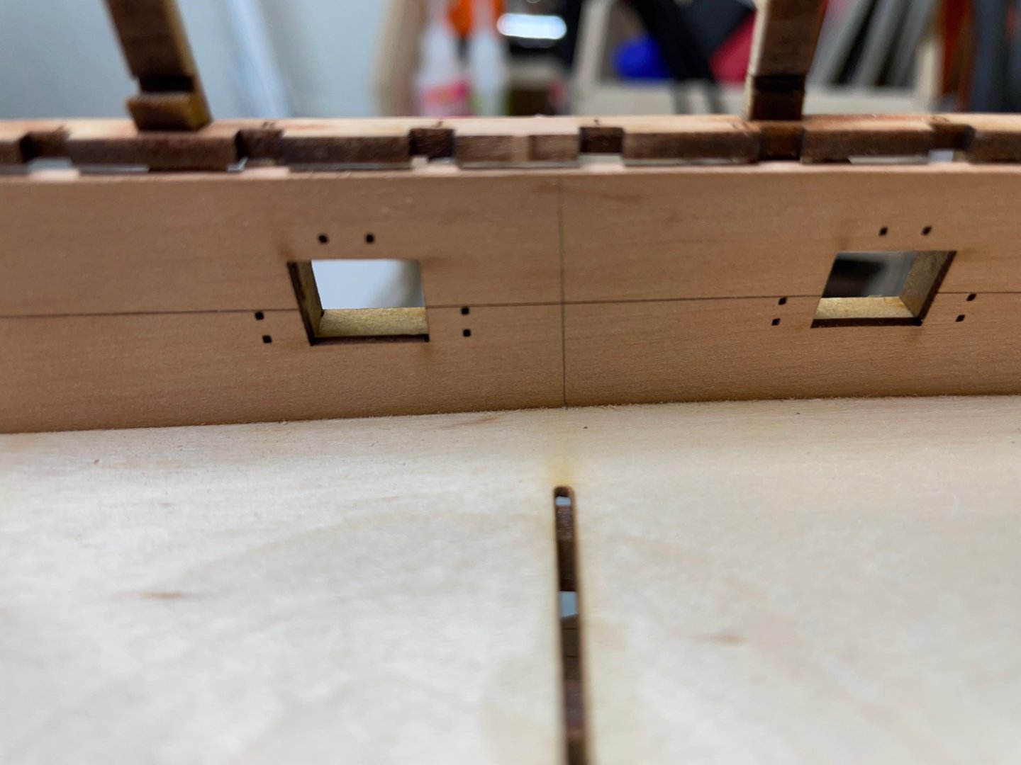
Photo 145: Checker Pattern glued.

Photo 146: Gun Deck Pattern. I brushed diluted glue to entire deck surface below and then placed this part on top of the deck, supported with clamps and whatever small weight I find on my table.

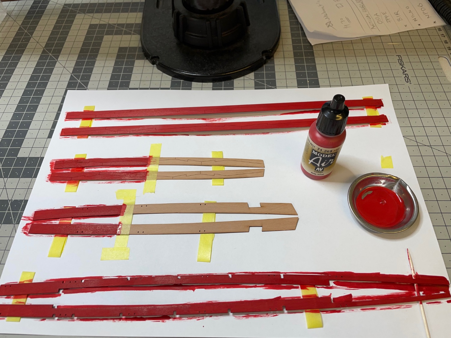
Photos 147-148: Lower Spirkettings and Deck Clamp Patterns. Painted.
By the way I tried Vallejo Model Color Flat Red (70.957) and Vallejo Model Air Red 71.269 on a scrap pearwood and I decided to go with 71.269. It looked better on pearwood to my eye than the flat red.

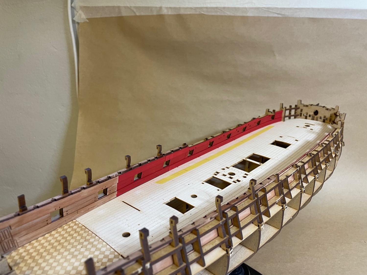
Photos 149-150: Current status.
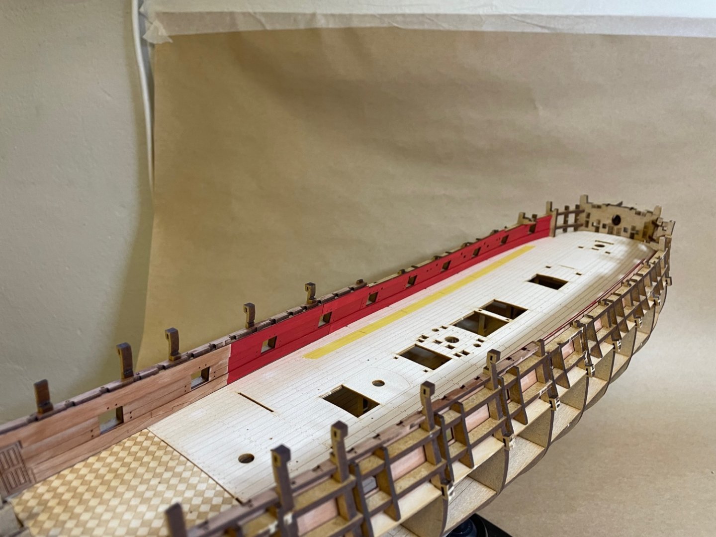
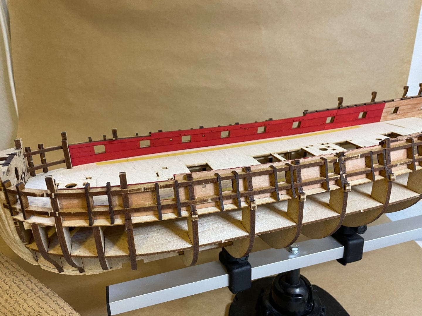
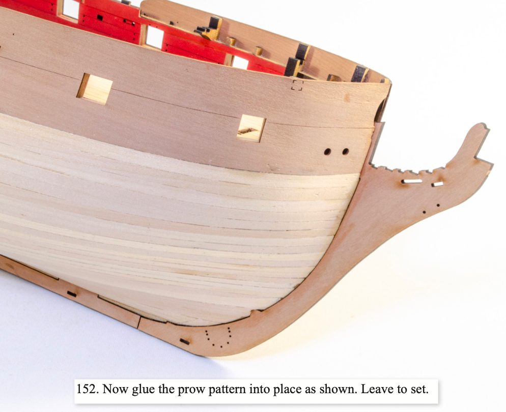
Photos 151-152: Stern Cabin Bulkhead Pattern (197) and the Stern Cabin Seat Pattern (198) glued in position.

That's all for today. Thanks for watching!
-
6 minutes ago, James H said:
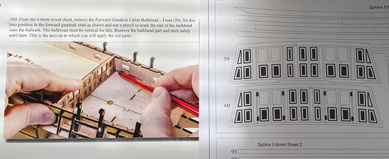
I wouldn't worry too much about it. It's obvious that it's part 60 when you are working on the model. I write all this away from the bench session with about 6 different files open, switching between them. The occasional thing will slip through the proof, but they won't cause any problem. We probably spend more time on manuals than anyone else, so you'll have to forgive little things like this.
Definitely too small error to worry about and so far my experience with the manual's visual and explanatory qualities as well as guidance to the builder have been great. 💯 In the beginning of my log I wrote as the first impression that this manual ranks all time 2nd best after Amati Orient Express manual but as I am building it, it is likely that my ranking will change at the end. 😃
-
-
BUILD DAY 9: 1,5 hour / Total: 14 hours
Some details installing the Quarterdeck Beam Spacing Patterns.
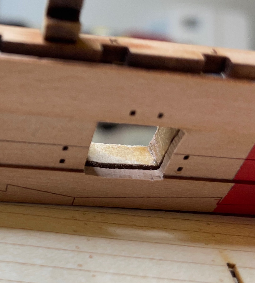
Photos 136-138: Their rear ends should slot into the timbers at the top of the stern. This needs a slight sanding to form a square opening at the end. The last photo is actually from the other side than the first two.

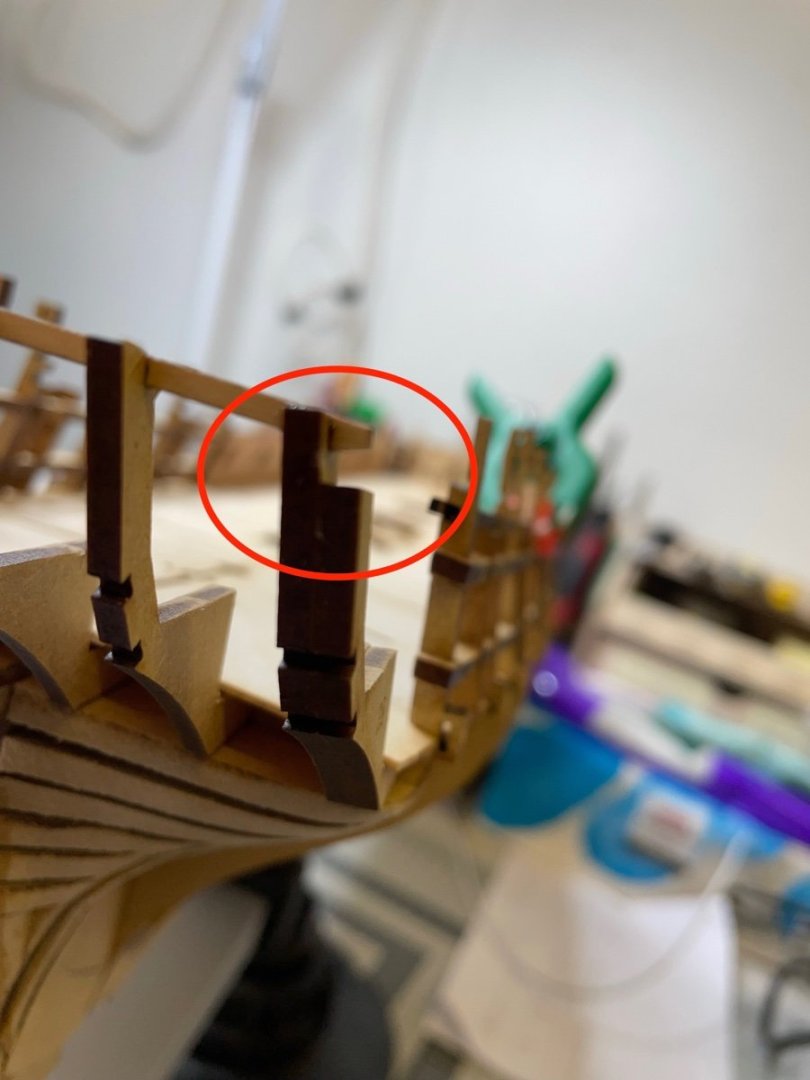
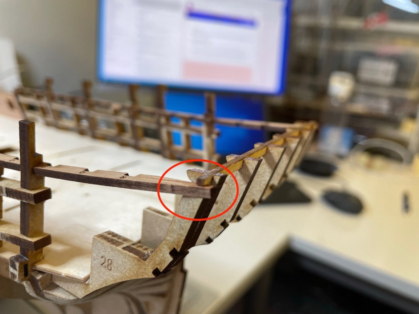
Photo 139: Both Quarterdeck Beam Spacing Patterns installed.
Photo 140: Next, Rear Inner Bulwark Gundeck Patterns. Installed the same way as the front ones, nothing special. Had to do small corrections using sanding block. In the photo the one on the right is ready and the one on the left is waiting for the glue to dry.

- mtaylor, Oldsalt1950, BenD and 2 others
-
5
-
Time to glue the Inner Gundeck Bulwark Patterns, made from pearwood with nice laser details.
Photo 128: I used my Proxxon mini sander to sand inside the frames where the bulwark patterns will fit.
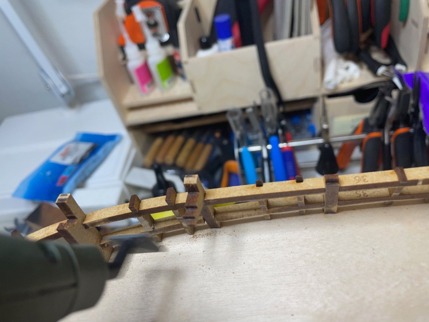
Photo 129: Here I dry-fit the Quarterdeck Beam Spacing Pattern (the part with A-B-C.. marks on the right) temporarily to take a good reference to fit the Gundeck Bulwark Pattern precisely.
Photos 130-133: Photos showing the progress of the front Gundeck Bulwark Patterns. I brushed diluted glue here as well.

I had to scrape below this bulkhead ear a little from under with a narrow file. This was pretty much the only correction I had to make.


Photos 134-135: I am also glad that they sit perfectly in contact with the deck pattern, with no gaps.

- ccoyle, bruce d, DonSangria and 7 others
-
10
-
-
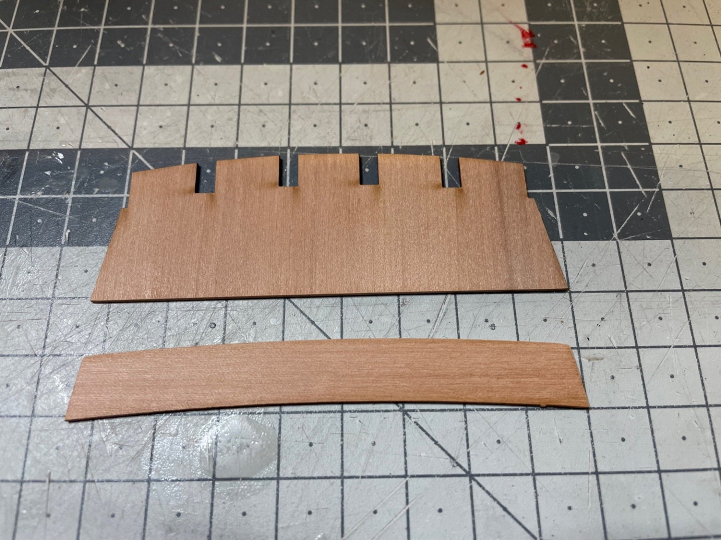
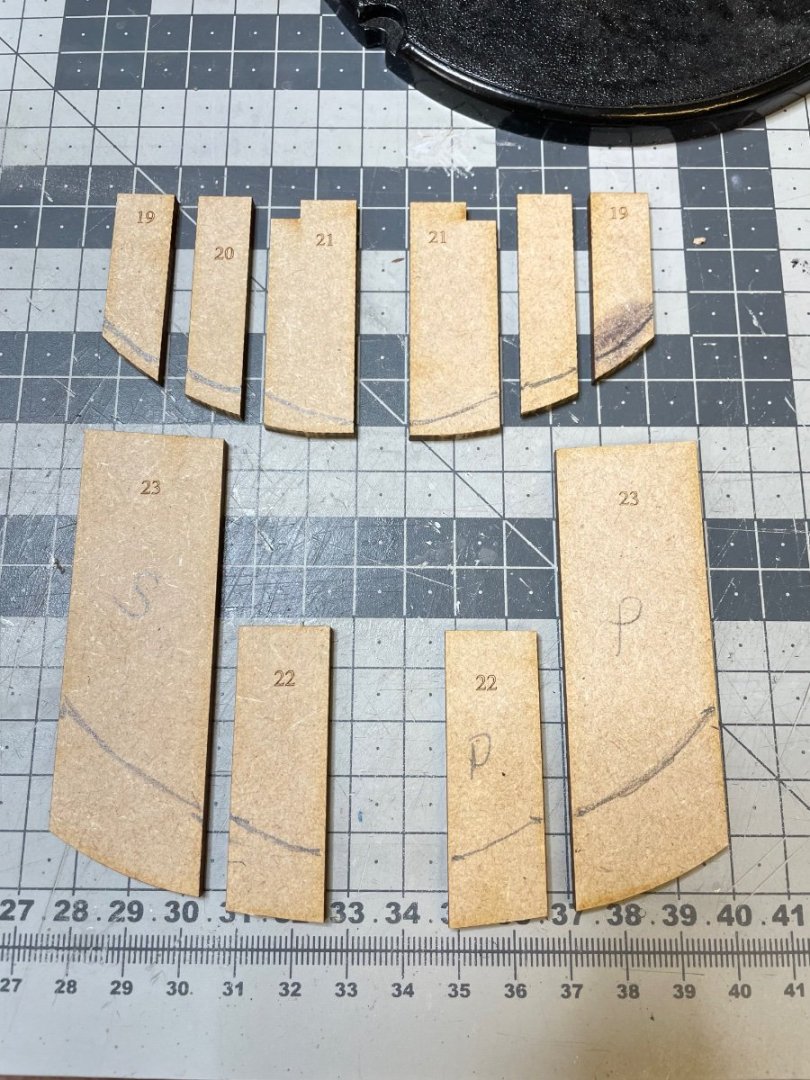
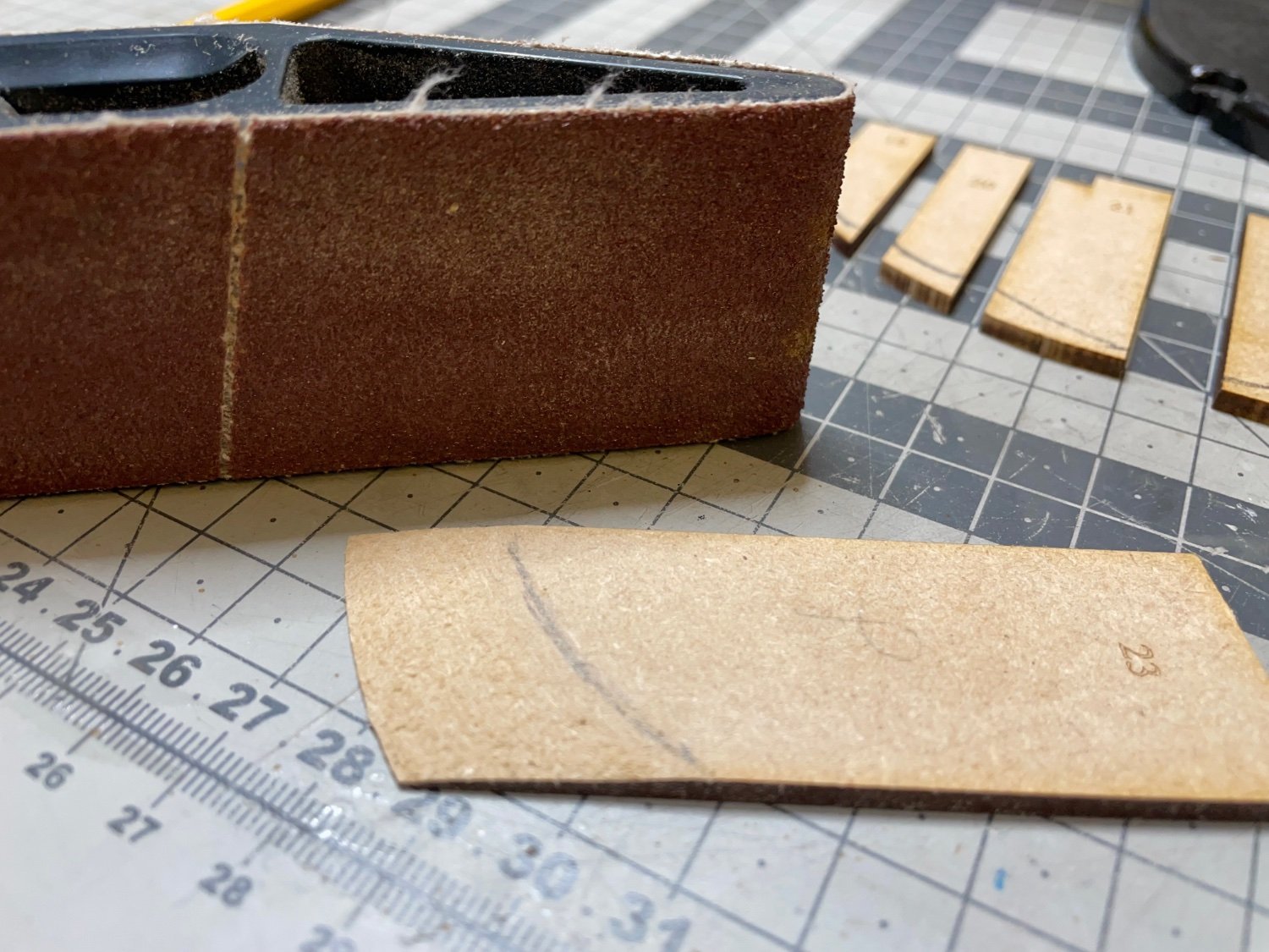
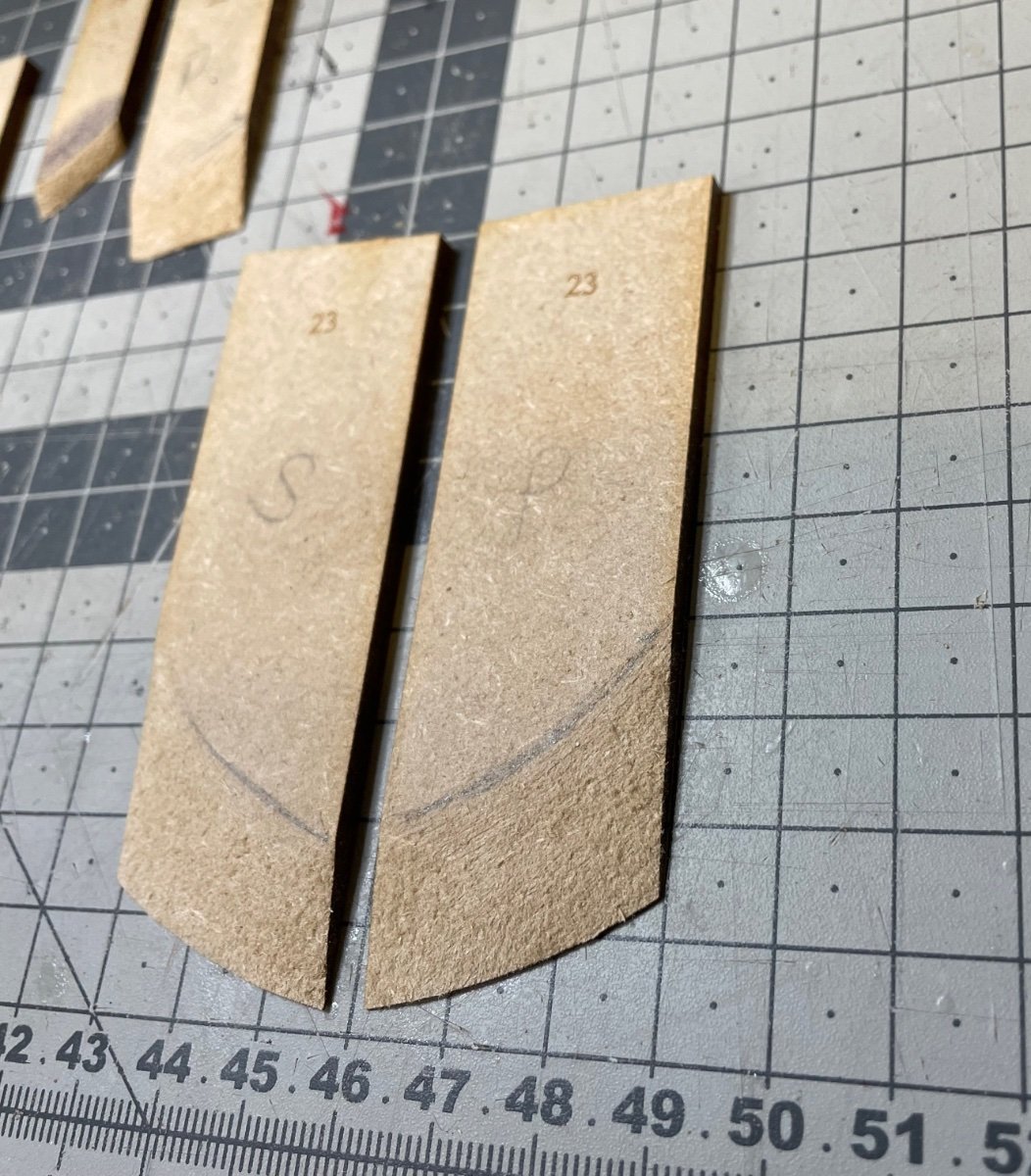
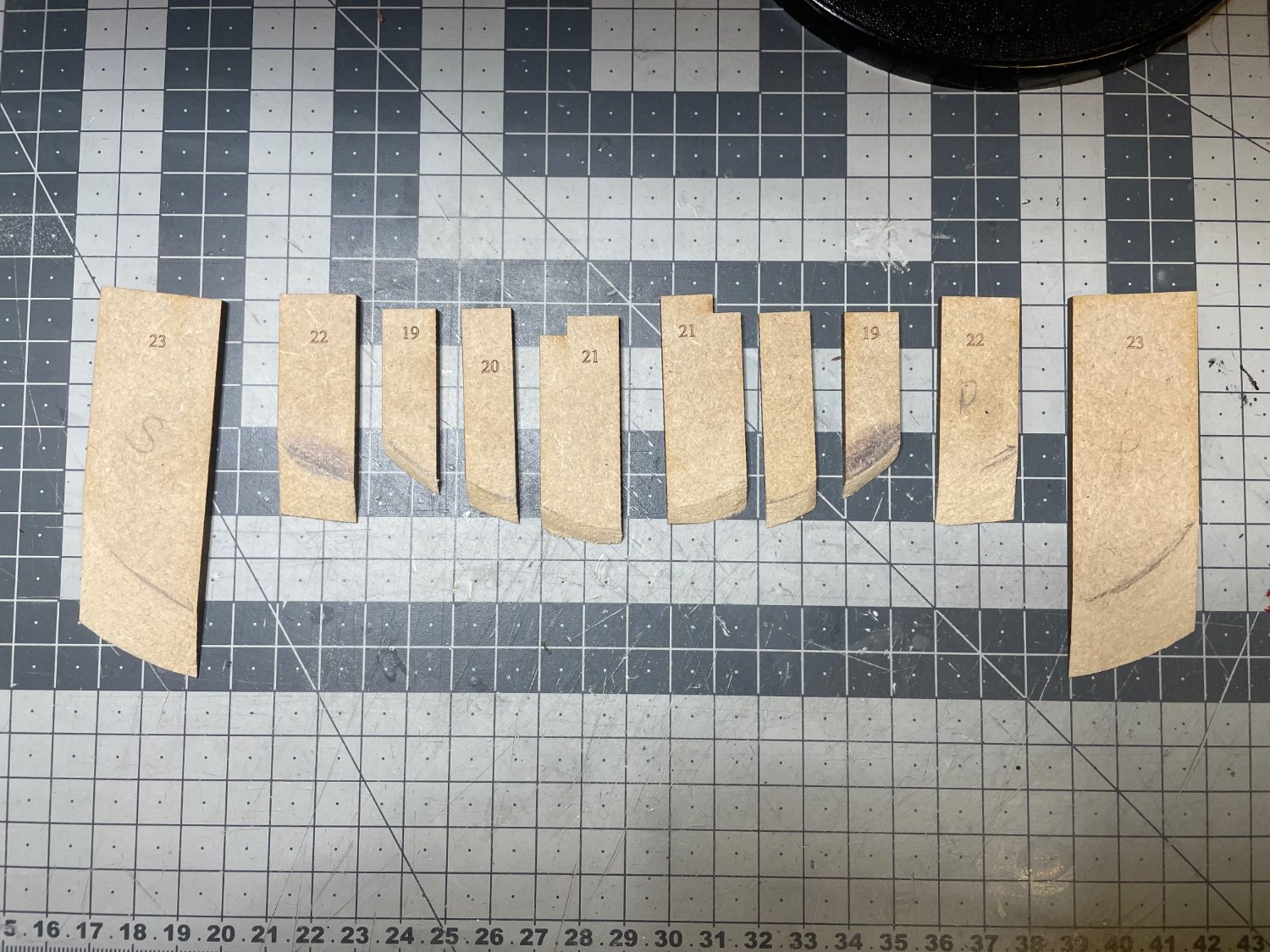
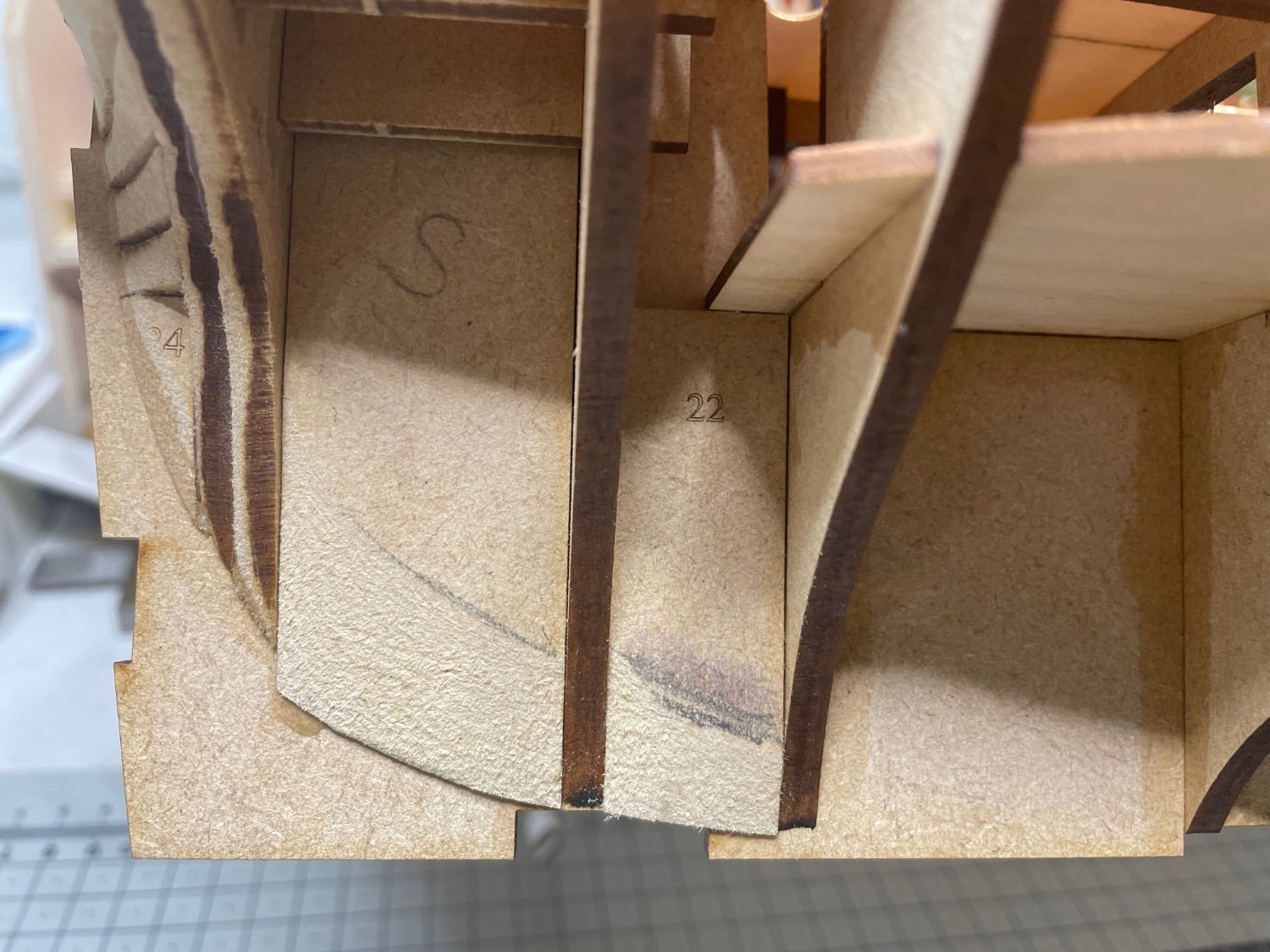
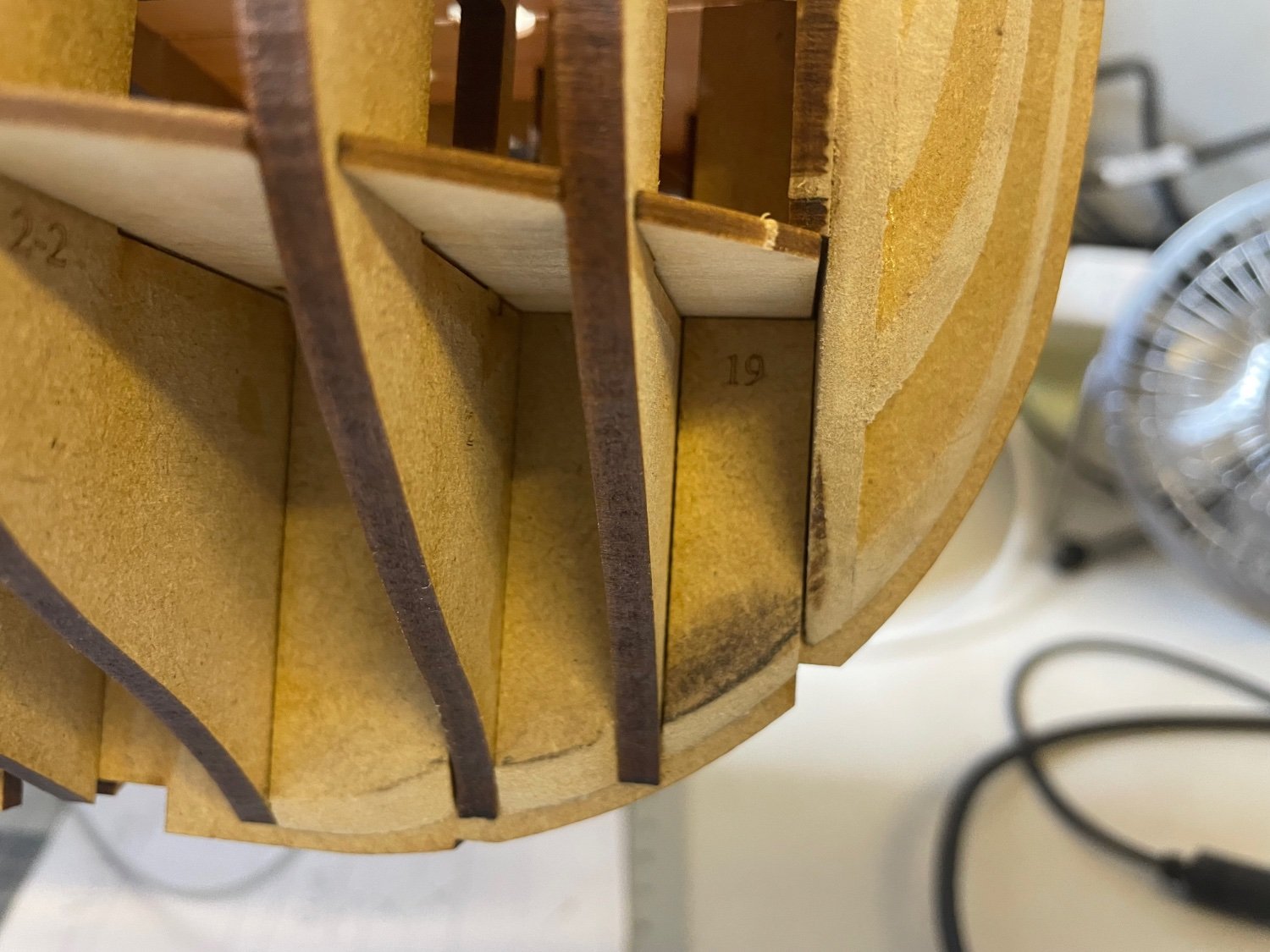
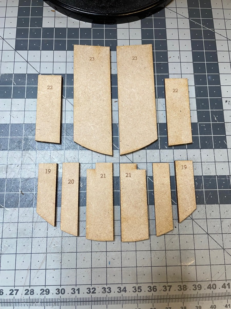
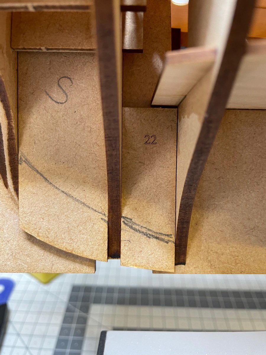
Photo 119: Bow and Stern Planking patterns.
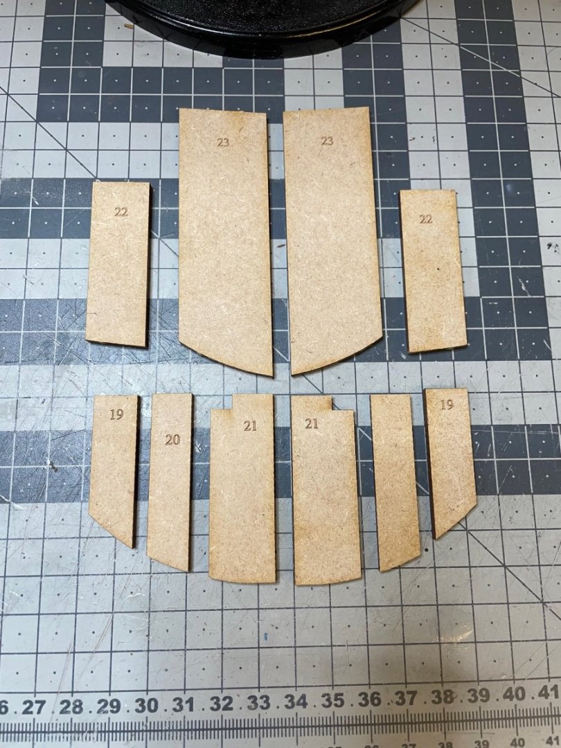
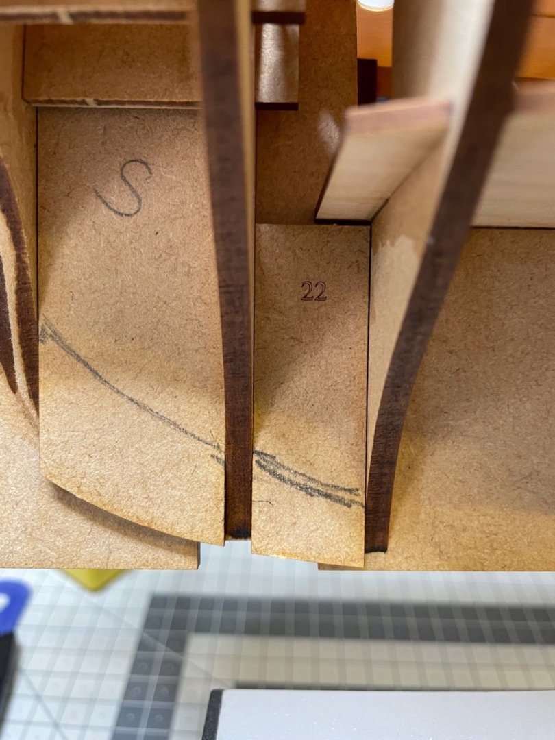
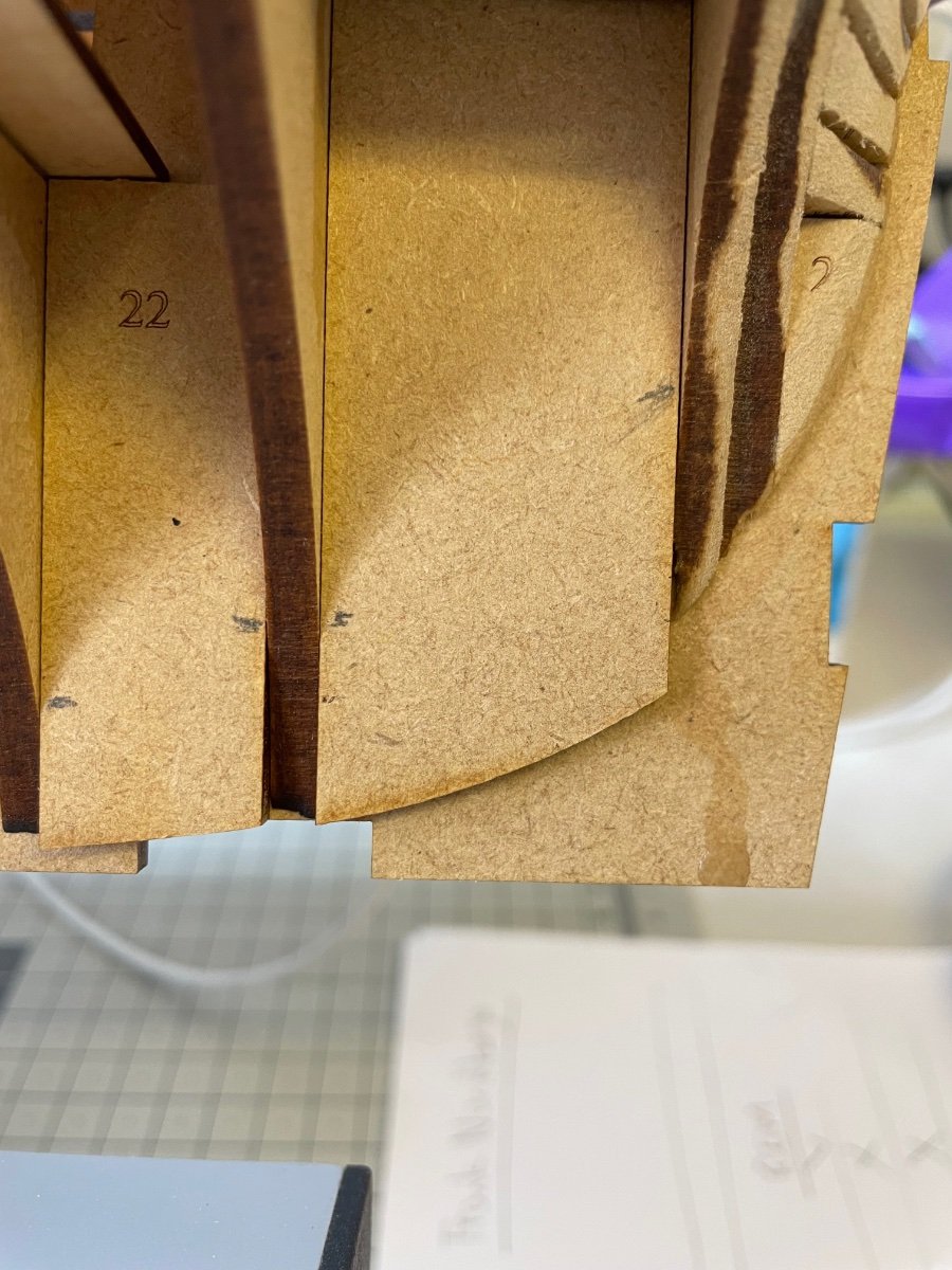
Photos 120-122: I marked them at the spot where the adjacent bulkheads are at the same level with them and combined the marks with a curvy line. Instructions do not mention where to mark the line but following the photos I had the feeling that's the right way to do.

-
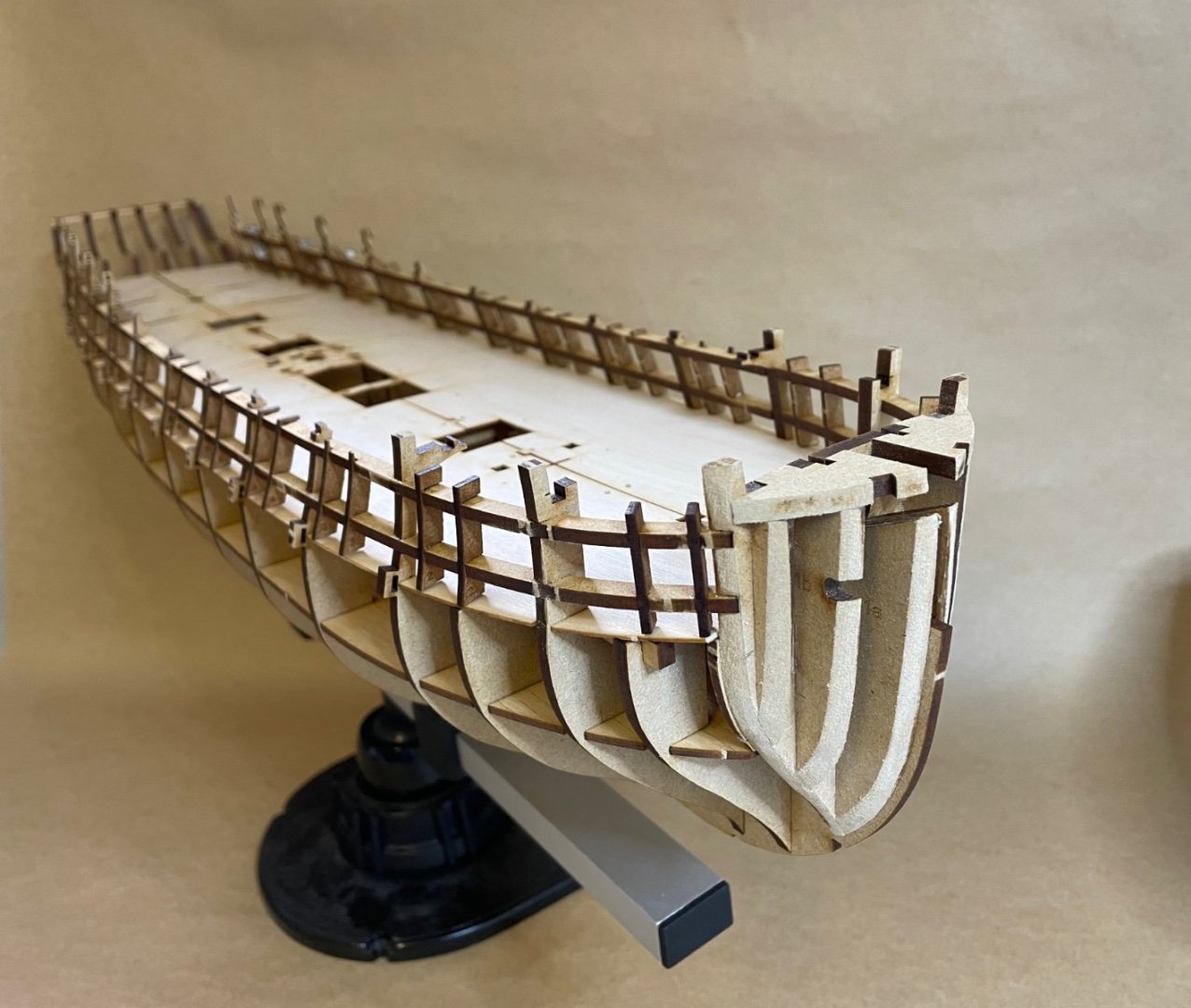
Photo 118: Status after the Vertical Gun Port Patterns are in place.
- mtaylor, vetman8953, bruce d and 4 others
-
7
-
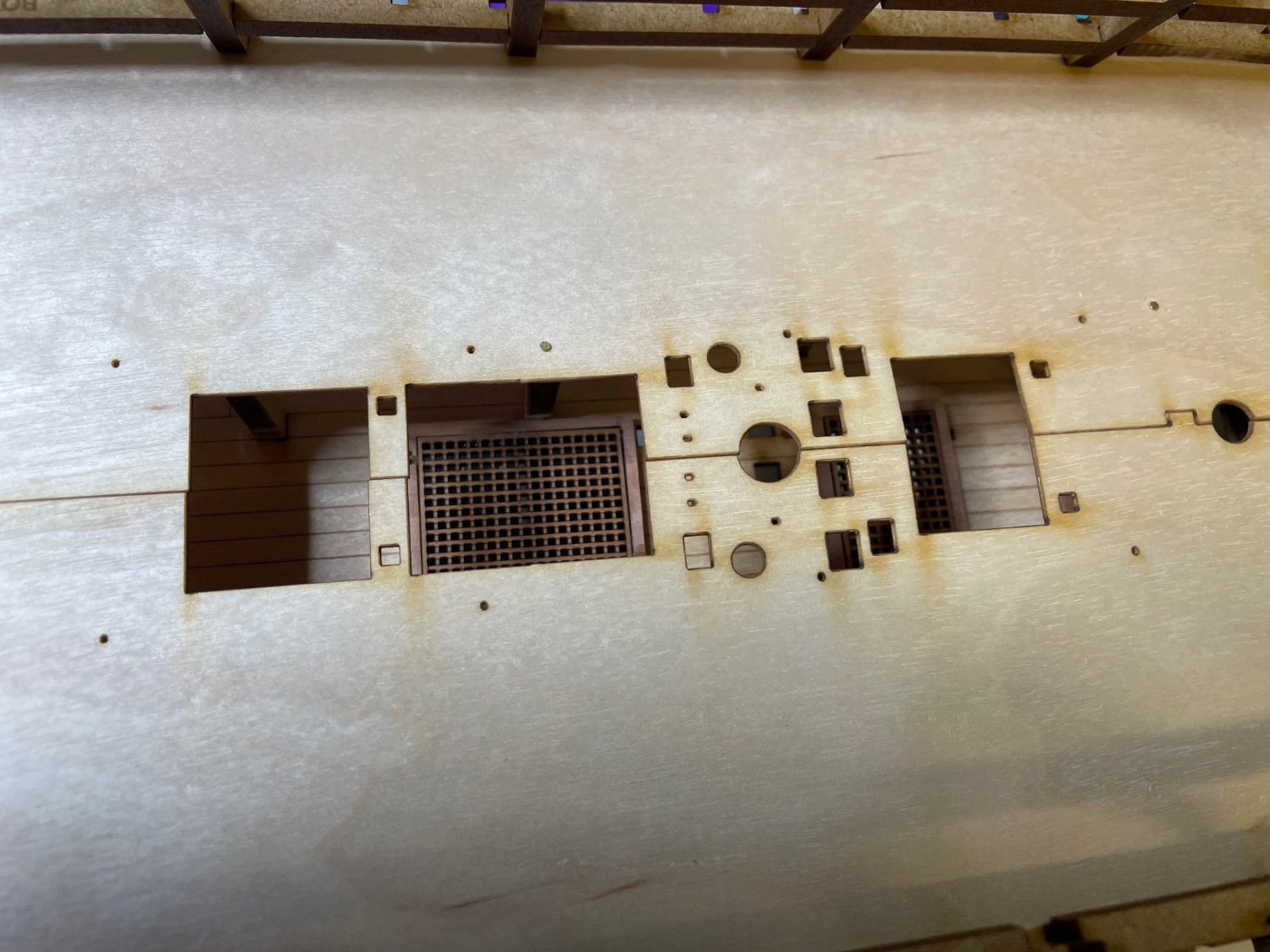
Photo 113: Status after Gun Deck Pattern installation.

----------Photos 114-116: Vertical Gun Port Patterns. I broke 3 of them removing a bit carelessly from the board. Quite delicate those tiny necks. I fixed them by dropping a tiny drop of thin super glue and letting the paper below also stick to it and enforce.
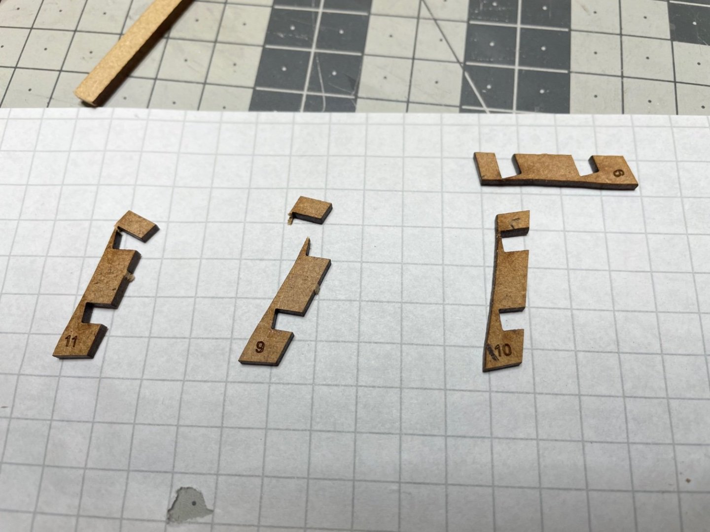
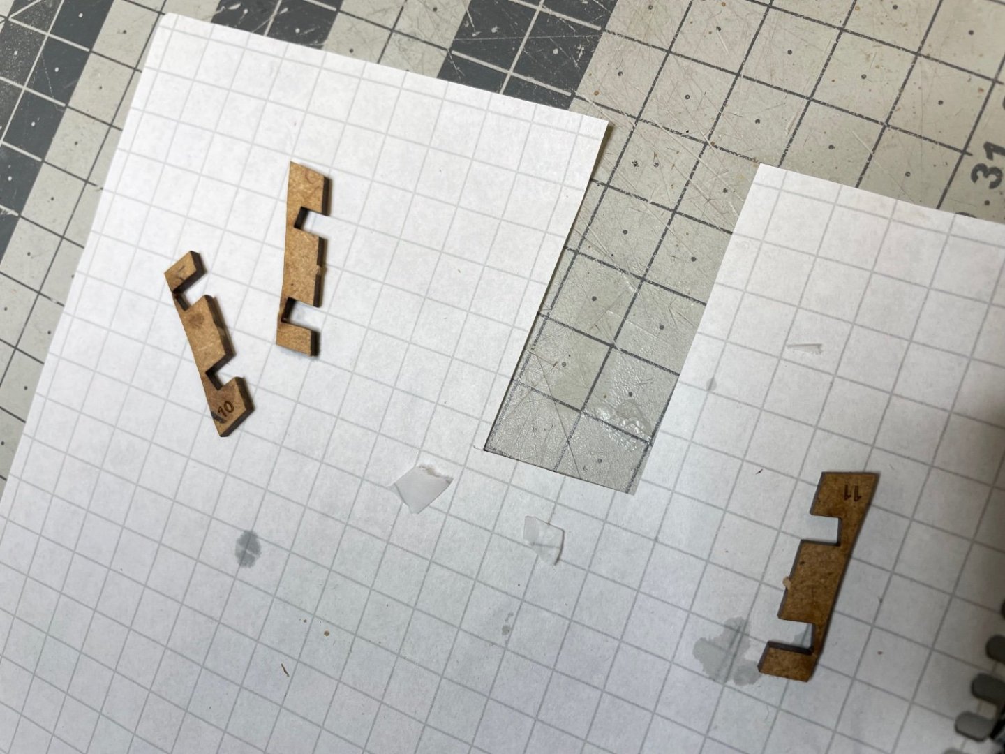

Photo 117: Waiting for the brushed glue to dry.
- bruce d, Oldsalt1950, Ryland Craze and 3 others
-
6
-
BUILD DAY 7 and 8: 3 hours / Total: 12,5 hours
Today I am logging two days of work, it will be a long set of posts.
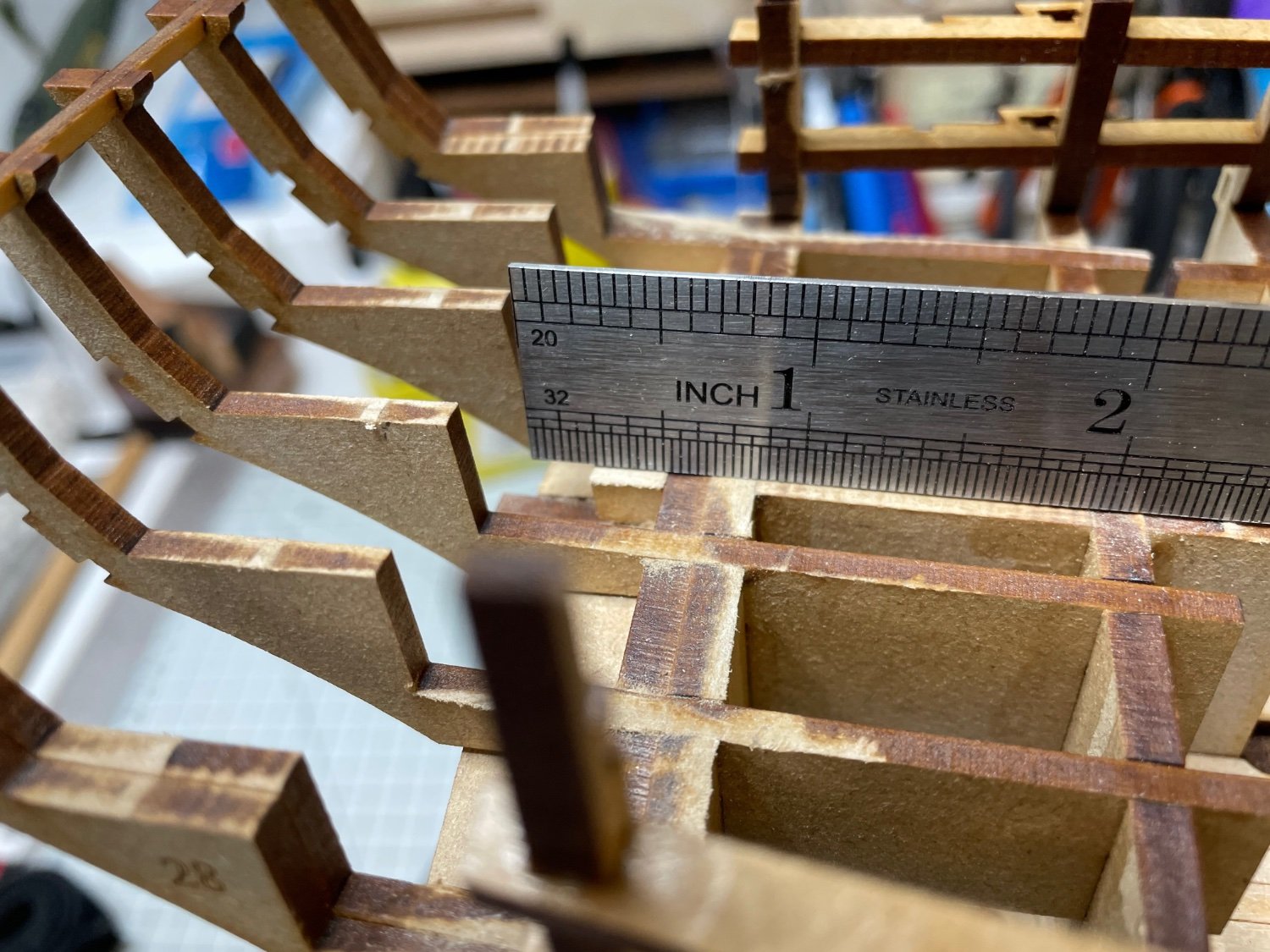
Photos 106-108: Sanding the Stern Counter Frames to align flush with the rest of the deck elements at parts like marked in the photo. I used straight piece of wood and ruler during the progress to check.

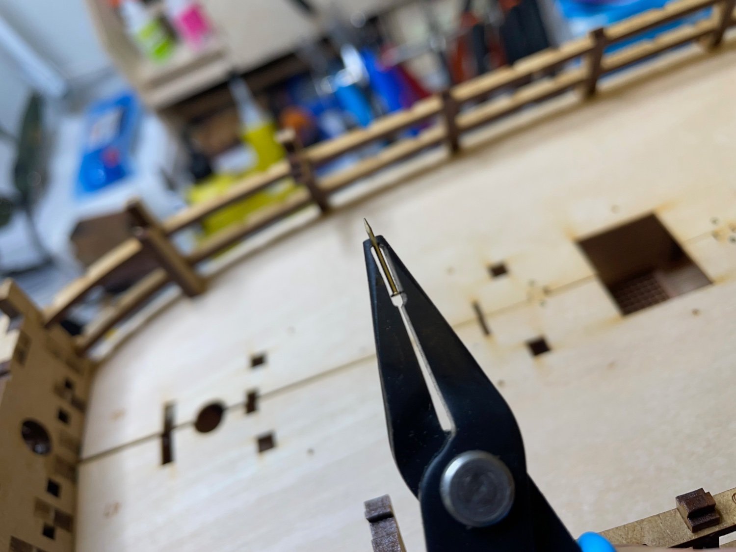
Photos 109-112: Installing the Gun Deck Pattern, coming in two pieces. I used this pin pusher I bought from Micromark. It grabs the pin perfectly and lets you make small-trip-at-a-time pushes that help you insert the nail more accurately and without risk of bending/twisting it. Recommended.I nailed it in the center edges and brushed diluted glue from the underside. I am satisfied with the result. There will still sit another layer on top of this, so I hope I will be able to correct the small misalignments visible in the pictures.


-
1 minute ago, James H said:
You're not really going to see it at all, unless you have a medical endoscope!
Personally, I'd just leave it as it is.
I thought the same about visibility, my main reason for considering was if varnish would be good for protecting the wood. But here I'll stick with your recommendation.
-
-
BUILD DAY 6: 2,5 hours / Total: 9,5 hours
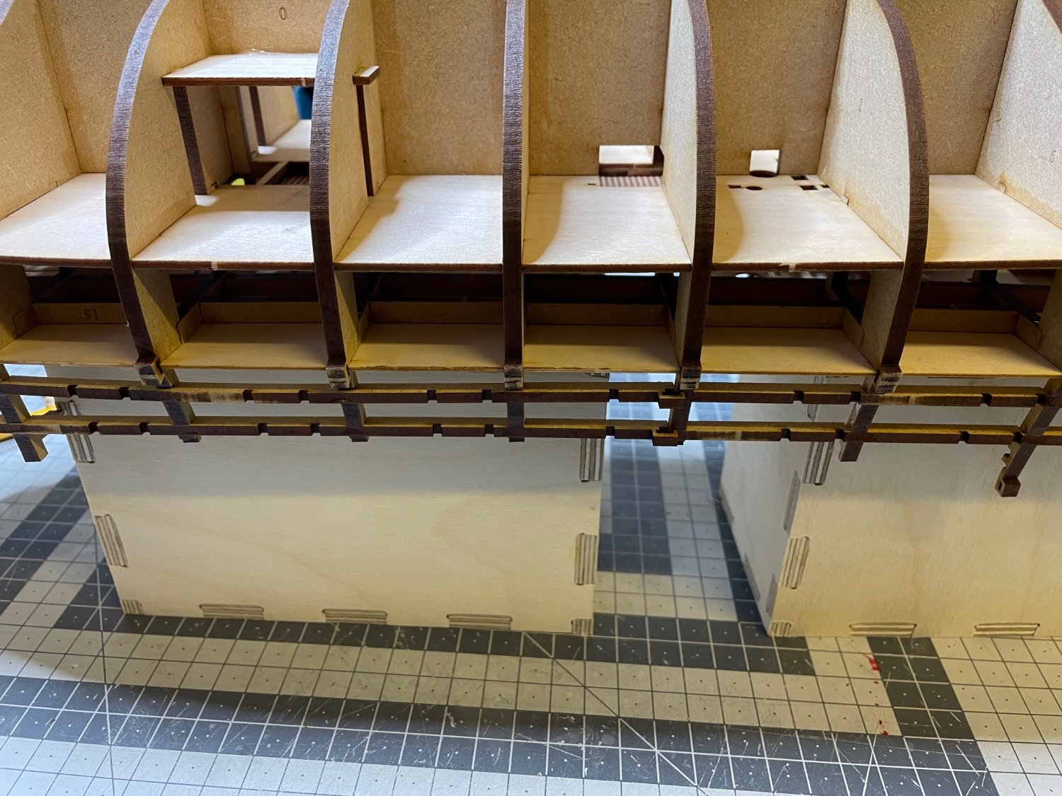
Photo 83: Gun Deck Support patterns (2 x #1d) in place.

Photo 84: Gund Deck Support Beams.
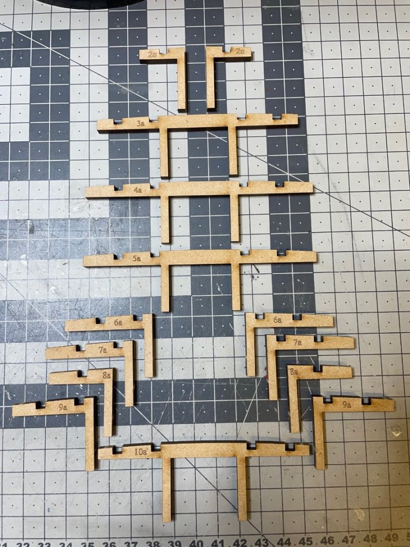
Photo 85: Time to time the parts needed slight sanding, just enough to remove the laser char, in order to fit their sockets.

Photo 96: At some parts I used a right angle until glue is dry to ensure a vertical alignment.

Photo 97: All support beams are in place. By the way I used UHU Hart glue at this stage.
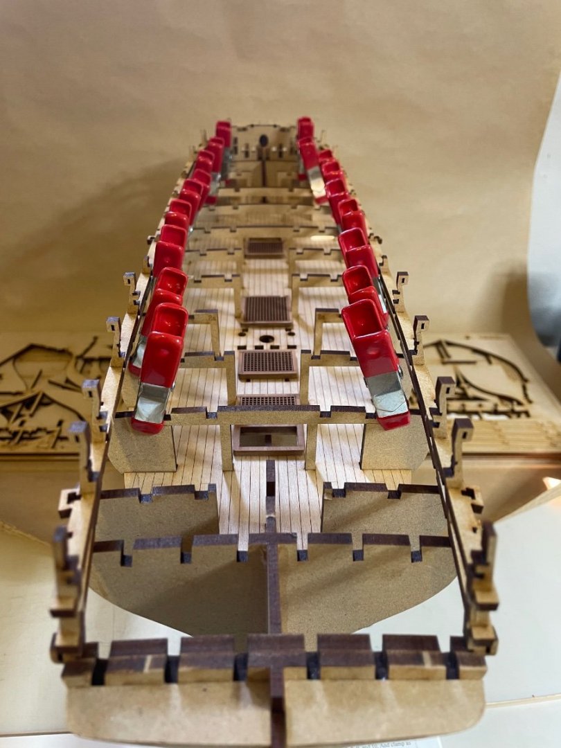
Photo 98: Longitudinal Deck Beams, which will sit on top of the support beams I installed above. They have accurately made slots.
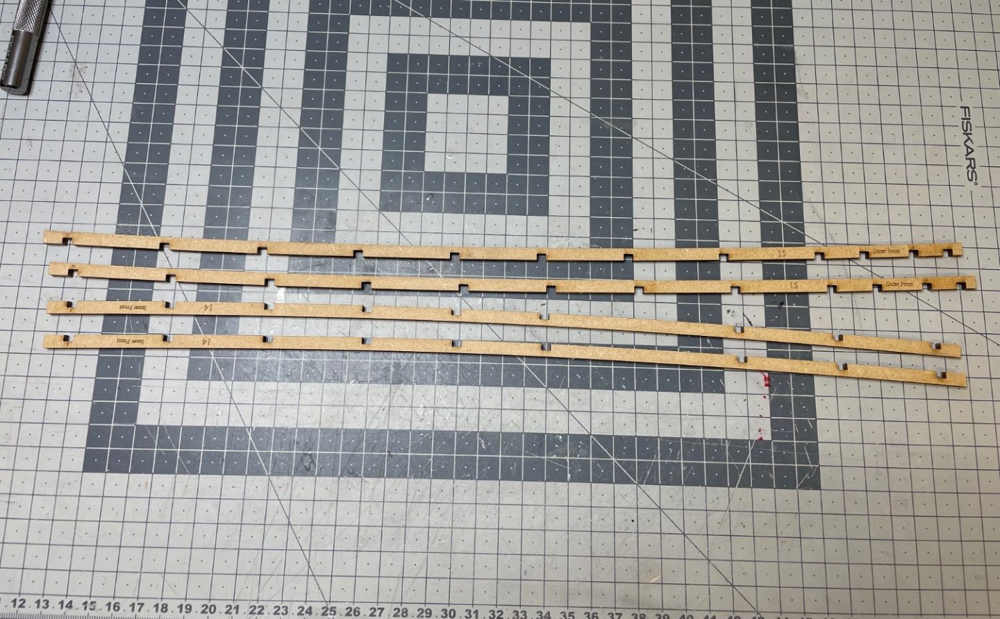
Photo 99: I brushed in diluted wood glue here in all joints. At some parts I used a soft clamp to keep joints completely in place while glue is drying.

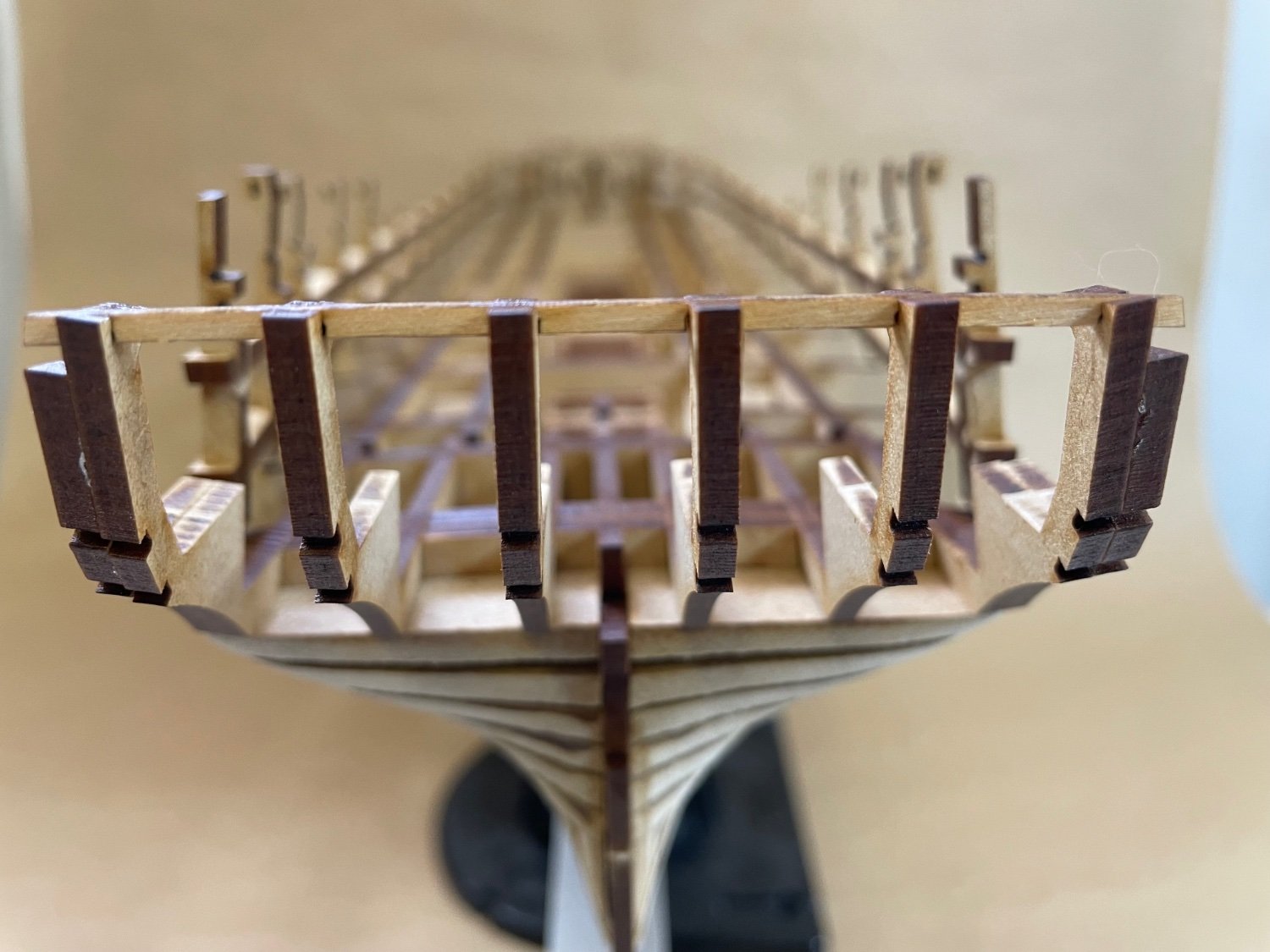
Photo 100: Yes! 100th photo of my build log! And this is how my model looks:
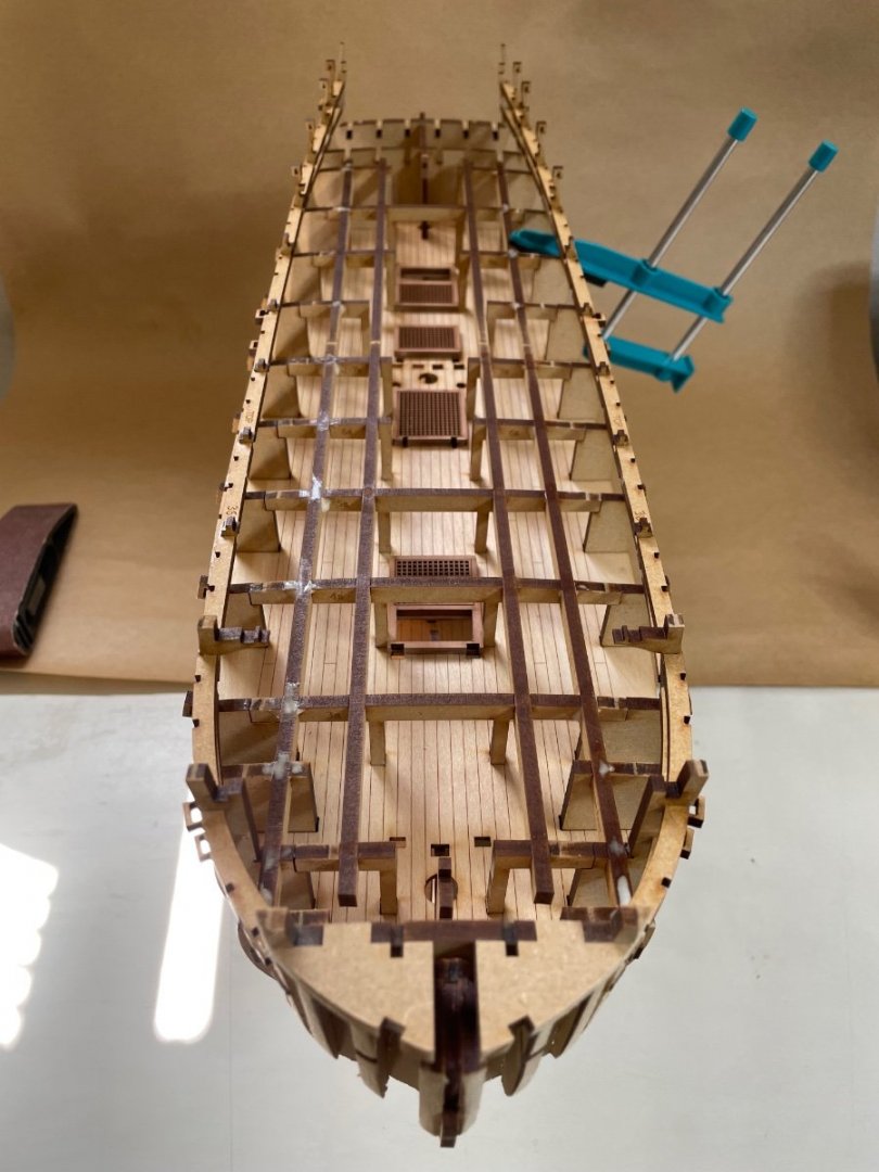
Photo 101: Side view.
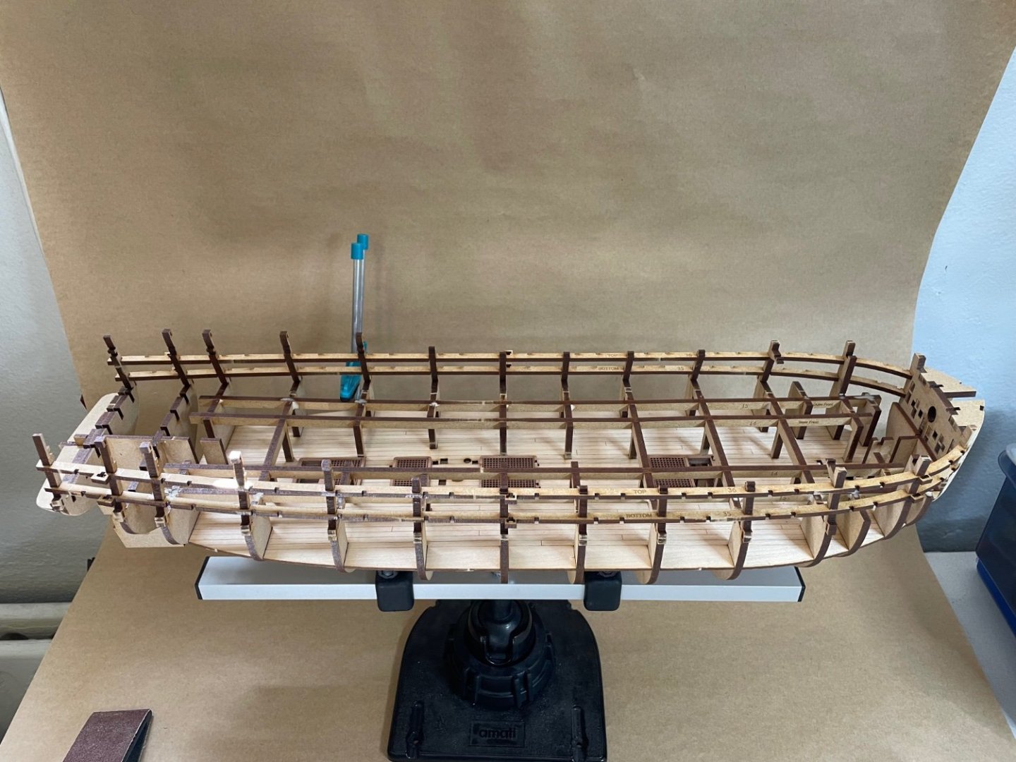
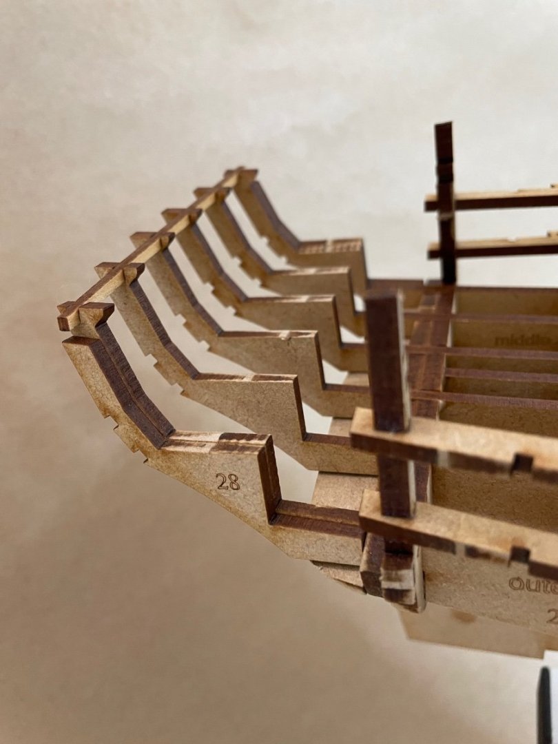
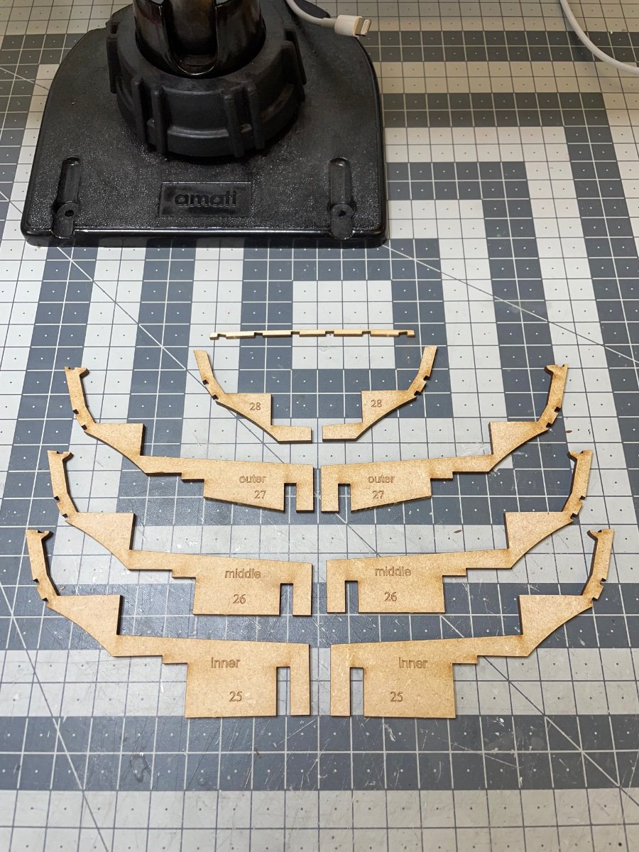
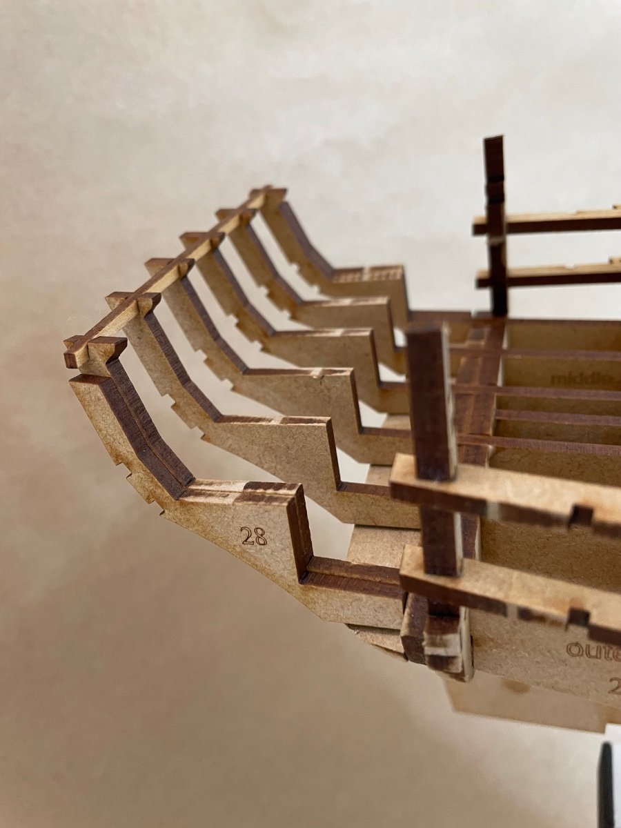
Photo 102: Stern counter frames and their spacer. Their locations are clearly labelled on the MDF as inner, mid and outer.

Photos 103-105: They fit nicely with only slight sanding time to time. I brushed diluted glue, except at parts #28 where I glued directly with UHU Hart.
Note that these frames are not always vertical. They make a slight angle towards the keel. Therefore their horizontal surface is not flush with the bulkhead or the Longitudinal Deck Beams. You'll need to get them level by sanding before moving any further. This is explained clearly in the instructions.

- Paul Le Wol, mtaylor, bruce d and 6 others
-
9
-


HMS Sphinx 1775 by aydingocer - Vanguard Models - 1:64 - Revision #2
in - Kit build logs for subjects built from 1751 - 1800
Posted
If it occured to me before, I could have used them for Upper Hull Side Patterns, too, like you did. Instead I used nails.