HOLIDAY DONATION DRIVE - SUPPORT MSW - DO YOUR PART TO KEEP THIS GREAT FORUM GOING! (Only 44 donations so far out of 49,000 members - C'mon guys!)
×


Chuck
-
Posts
9,660 -
Joined
-
Last visited
Content Type
Profiles
Forums
Gallery
Events
Everything posted by Chuck
-
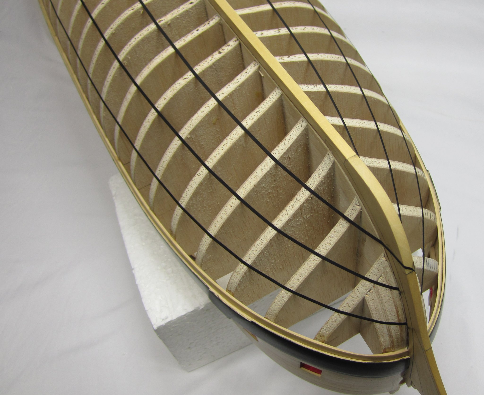
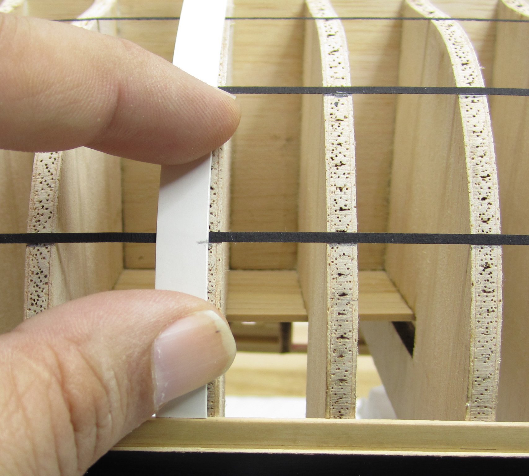
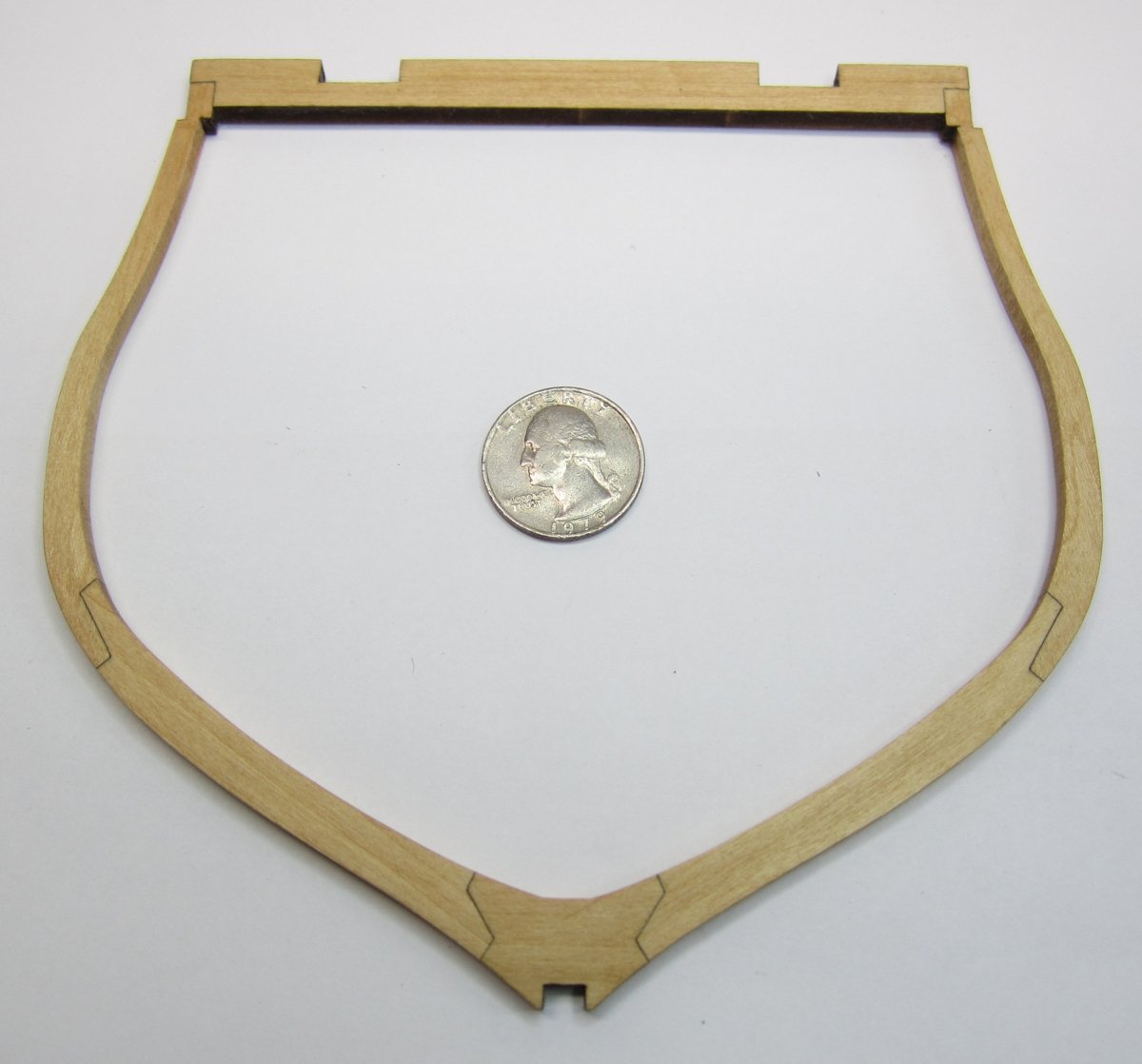
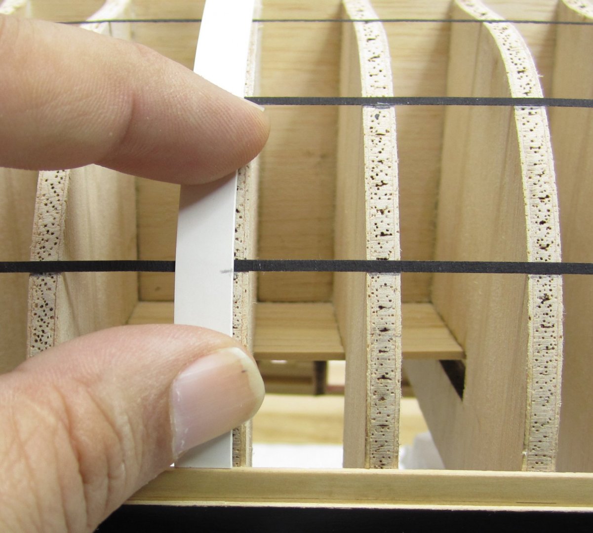
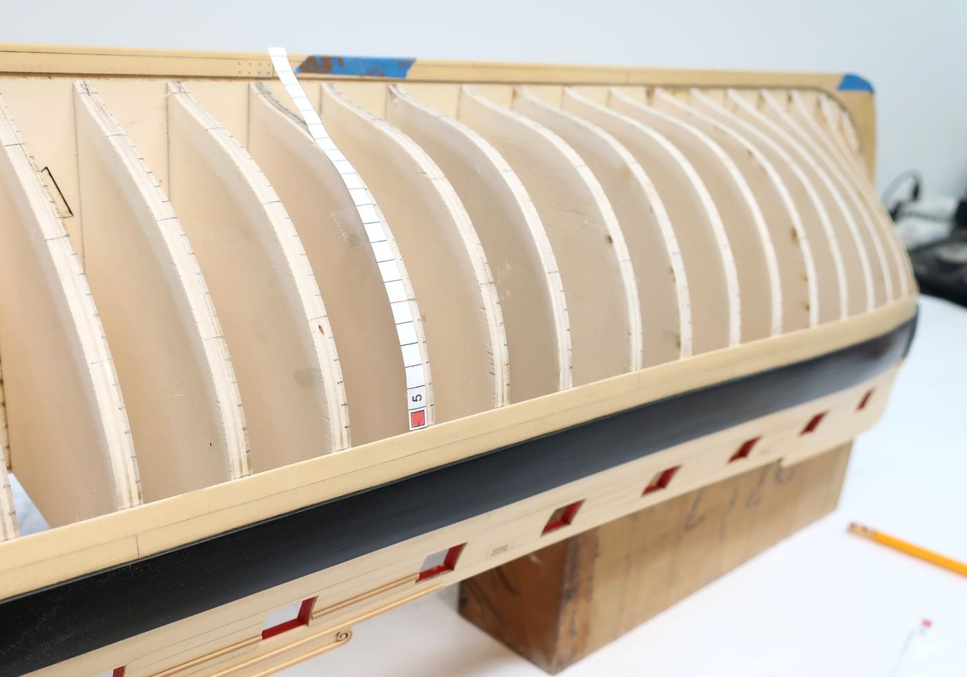
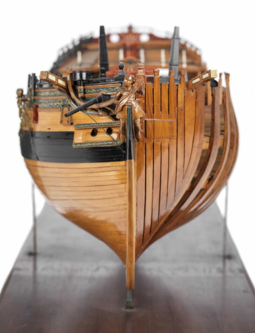
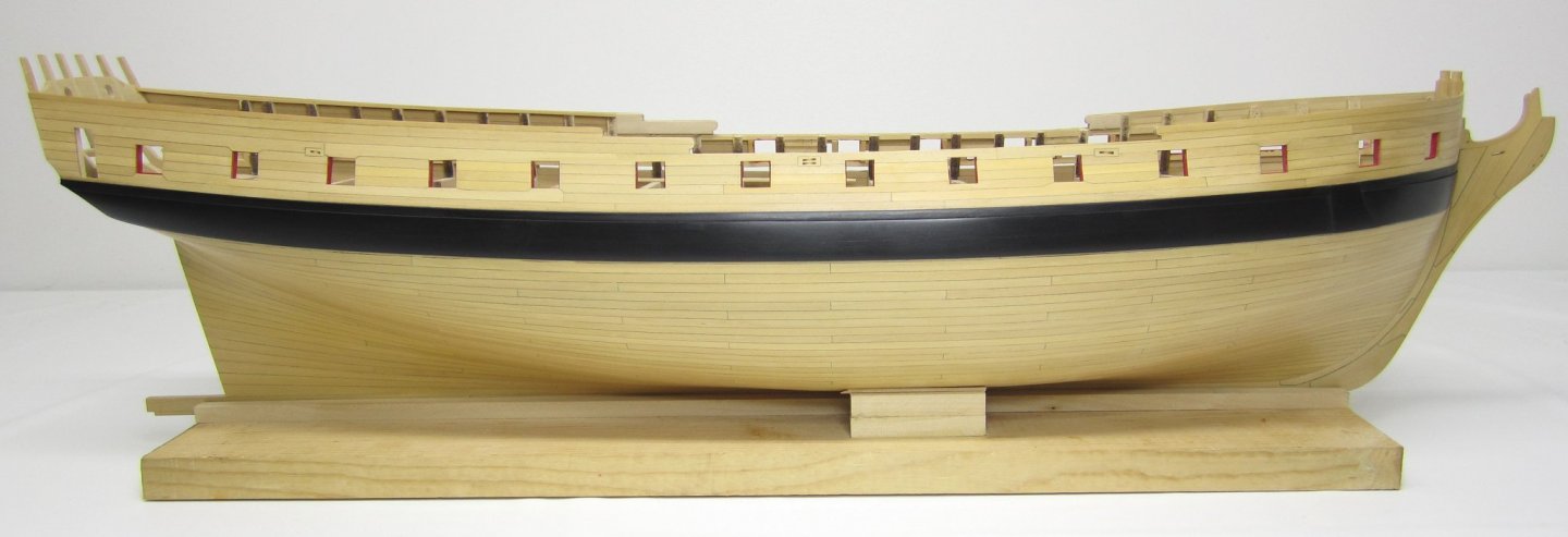
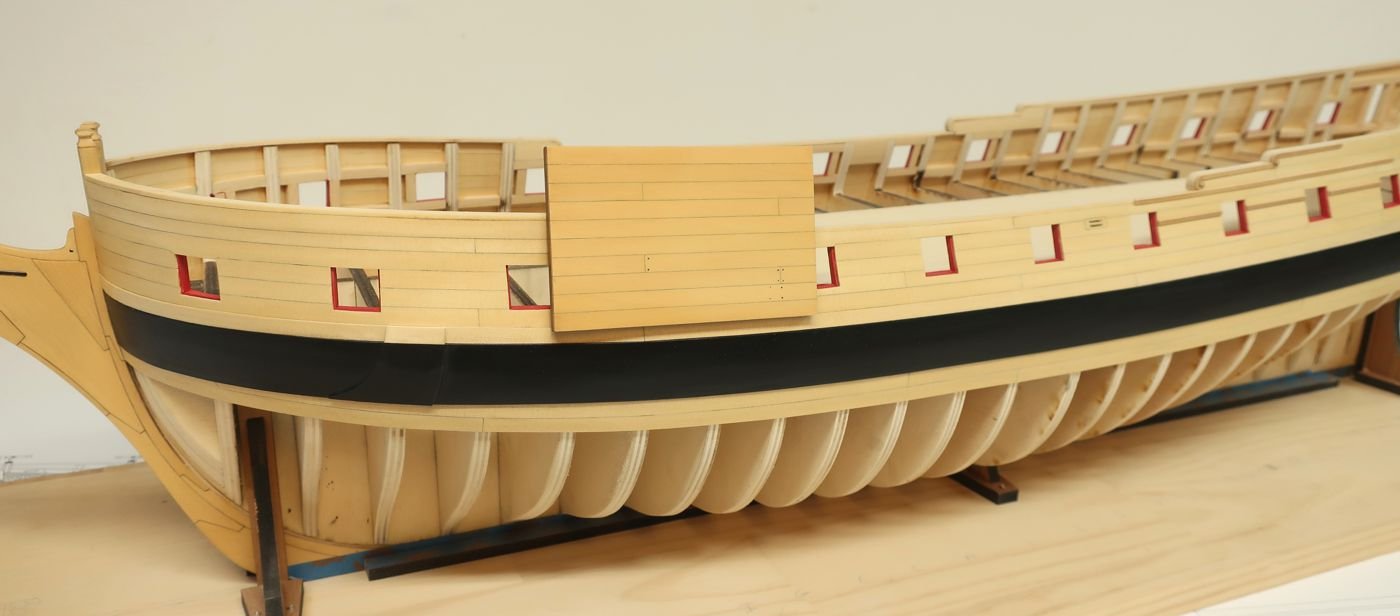
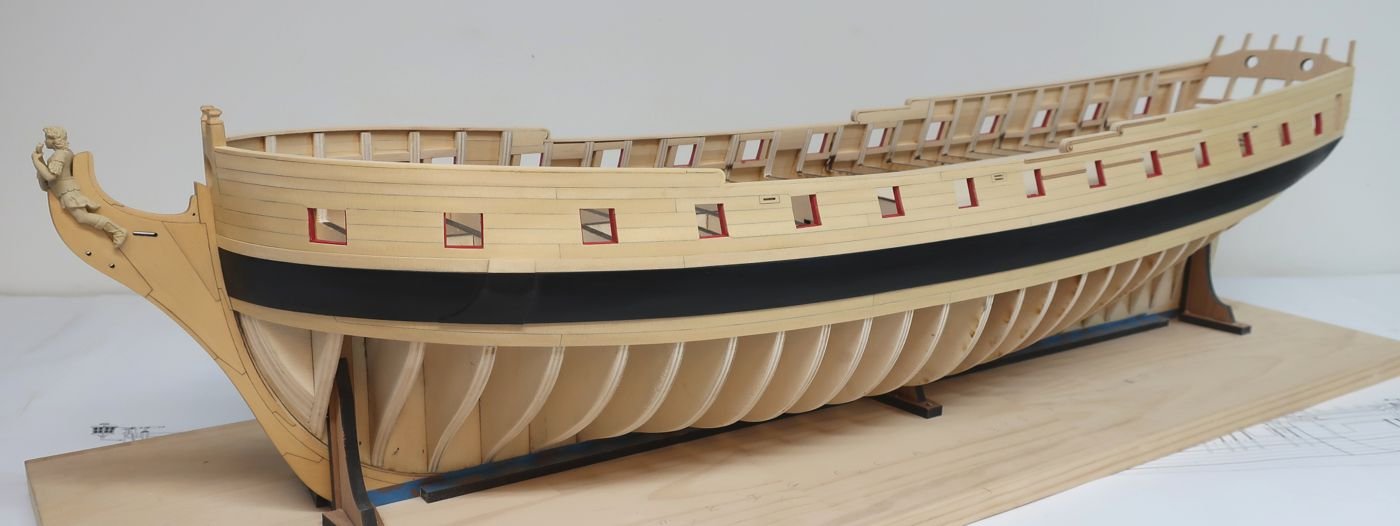
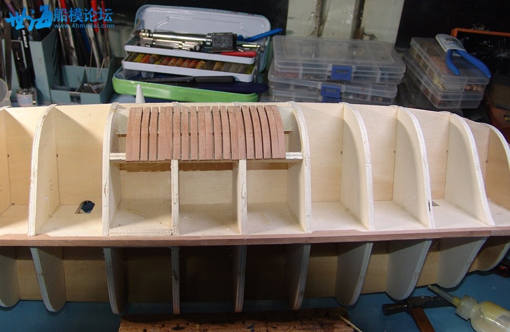
 Ok guys.....the tedious part of lining off the hull is now completed. Some background info..... On the contemporary model, there are 25 strakes below the below the wales. There are no drop planks or stealers at all. I have however, added one drop plank at the bow which is typical on other contemporary models of frigates. This will make it easier to get a good run of the planks at the bow so they wont narrow too much into the rabbet. We already have two strakes on the hull below the wales so that leaves 23 more to line off. Now....if you remember....I have showed how I line off a hull many many times. I wrote about it in exhaustive detail for Cheerful and for the longboat etc. There is also a PDF in the database. Having said this, 95% of the builders still dont bother lining off their hulls. This is to their disadvantage. They usually just grab some pre-milled strips and start planking while hoping for the best!!! Its a cross your fingers approach. You want to avoid this as much as possible especially on a hull that wont be painted below the waterline or plated with copper. We are shooting for this below......but with one drop plank at the bow and 33% larger. You can see some photos of my lining off on the first Winnie model I made below. Remember that on the first model I didnt use any drop planks at the bow so it was a bit different. Planking fans......some math.......some artful tweaking......about 50% math and science and 50% art/creativity and eyeballing. So...............................I am taking a different approach on this newer larger model that I think all of you will be very thankful for. It took me about 36 hours to line off the new hull over 5 days. To save all of you the time, after lining off my hull I created a series of tick strips for every bulkhead edge. These marks can can be transferred to your model so you wont have to spend a few dozen hours lining off your hull if you choose not to. See the photo below. There are also templates for the stem.....and more for the stern post and along the bottom edge of the lower counter at the stern. You just need to print out the PDF and cut the strips out. NOTE the red square on the bottom of each strip.....this side of each tick strip sets against the edge of the plank already finished as shown. In addition, many of the lines are in red. These indicate the different belts on the model. There are four belts. It just makes it easier to plank the hull so you can treat each belt as a mini-project of its own. It makes the task of planking so much less daunting. In addition....the tick marks you make on your bulkhead edges should be made on the forward edge of each bulkhead. This is an important detail. This will take what was a week's work for me and turn it into just an hour or so for you. BUT.....you should still double check your work. You can do this by running a thin strip of black tape along the hull following your tick marks. You only have to do this for the red belt lines. This will be a double check to see if when you lined off the hull maybe a tick strip was positioned a little lower or higher.....you may need to adjust and tweak some. But this gets you 98% of the way there. NOW.....I still believe that all of you should learn how to line of a hull if you have never tried this. Lining off your own hull is far superior as your hull may be slightly different than mine. For example....maybe the run of your wales was slightly different than mine at the bow...or at the stern. This will alter how your lining off will need to be done. But if you are close to my reference lines and the run of your wales are close to mine...... using these strips will get you 98% of the way there. I also think this is a perfect hull for trying to line off a hull for the first time as you have some tick strips to compare your own attempts to. I had written a separate detailed set of instructions for the first Winnie model on how to line off your hull. I went back in and altered the size info to reflect this larger scale but its still a good description of what I did on this latest model. In fact its exactly the same. So for any of you who would rather line off your own hulls you can read through this document below. Its a good instructional any way. Let me know if you have any questions. - liningoff.pdf
- 1,784 replies
-
- 32
-

-
- winchelsea
- Syren Ship Model Company
- (and 1 more)
-
HMS Winchelsea (1764) 32 gun frigate GROUP PROJECT INFO
Chuck replied to Chuck's topic in Group Projects on Model Ship World
not very difficult at all. You just need to cut out the area you want to create the box. then trace the curve of the bulkheads you remove to create the frame shapes. -
They are in stock already....everything is there. https://www.syrenshipmodelcompany.com/milled-lumber.php#!/Alaskan-Yellow-Cedar-PLANKING-SHEETS/c/36682020/offset=0&sort=normal
-
Almost forgot.....watch the bottoms of those first few bulkheads at the bow. They may damage your keel and stem because they arent faired yet. When you install them you will see that they extend below the rabbet strip on their forward edge. You might want to pre bevel them and angle them ahead of time to avoid that. Place one in a slot and you will see what I mean. Very hard to explain in writing. Most kits always have bulkheads that are too short at the bow. When properly shaped you should angle them at the bottom to avoid damaging that keel.
-
Now you know why it cost so much to ship them. They are very heavy. Makes for a heavy solid model also. Nice work.
-
HMS Winchelsea (1764) 32 gun frigate GROUP PROJECT INFO
Chuck replied to Chuck's topic in Group Projects on Model Ship World
Good...it would be nice to see you build a complete hull model again rather than these cross sections and parts...LOL. -
HMS Winchelsea (1764) 32 gun frigate GROUP PROJECT INFO
Chuck replied to Chuck's topic in Group Projects on Model Ship World
Doc, they can also be accessed on the right sidebar. Under the sponsor banner ads. Please let me know that you figured it out. Would love to see you start a build log and join the group. -
HMS Winchelsea (1764) 32 gun frigate GROUP PROJECT INFO
Chuck replied to Chuck's topic in Group Projects on Model Ship World
Doc .....all group builds are now at the top of the screen menu bar. Each group has its own mini-forum with tabs for build logs and other discussions.

-
If you wet it...only wet one side. I forgot which side you are supposed to add water to. Then flatten and leave in the sun.
-
It always happens to me too. I keep a heavy flat weight on it. Several large heavy stones. This helps but there is still warping at times.
-
Dont forget your rabbet strip between those. That changes everything and you would be surprised how much the shape changes. So avoid tweaking your stem until after you can test with the rabbet strip in position. Chuck
-
You will be catching up to me soon.!!!! Looks very good.
-
Yes but it makes the cedar too deep a yellow for my tastes. Its beautiful but not my preference.
- 1,784 replies
-
- 1
-
-
- winchelsea
- Syren Ship Model Company
- (and 1 more)
-
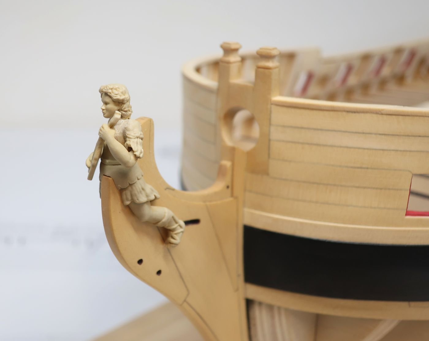
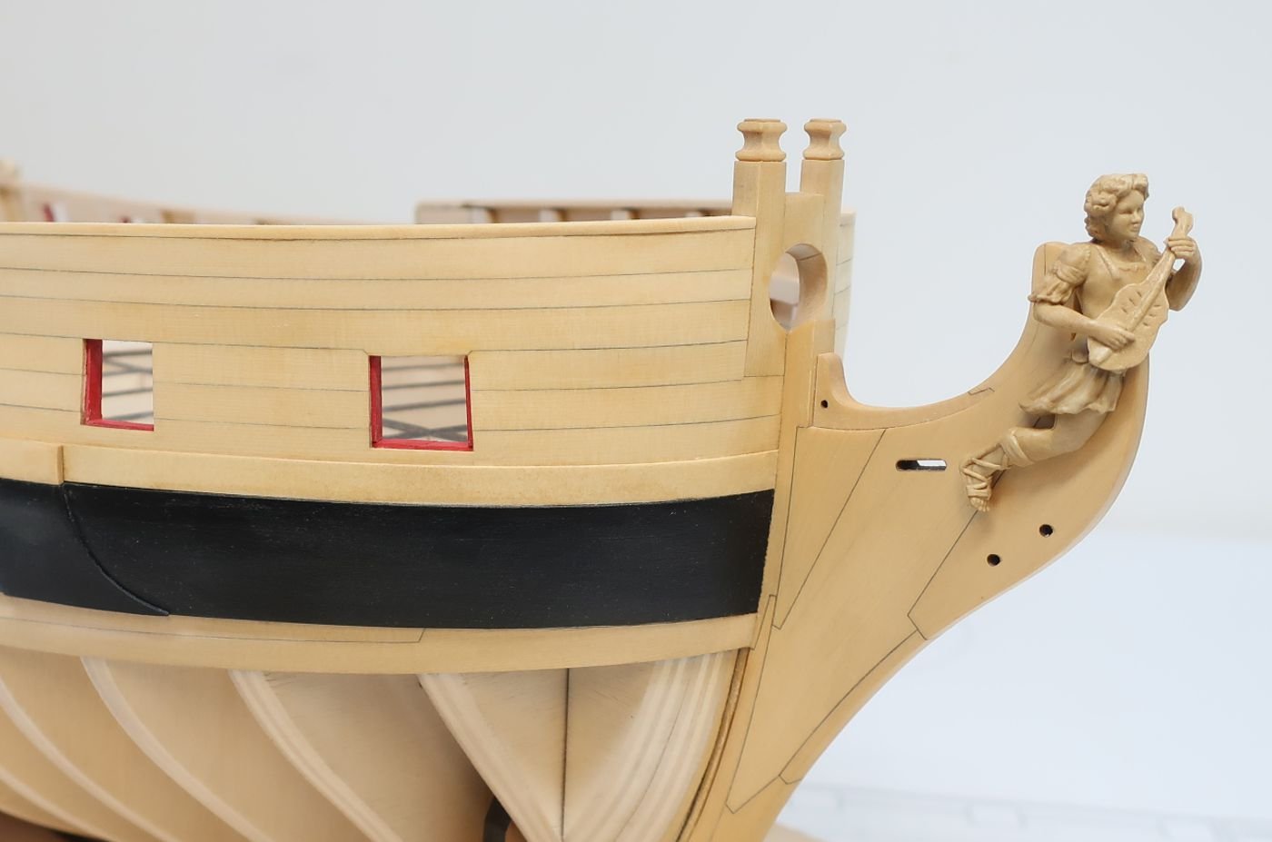
Actually I did. The issue with basswood is the fact that it is just too porous. It looked better than any finish I ever tried on Basswood but the end grain just soaked up too much color and still turned very dark. Almost black. But this is a basswood frame treated in the exact same manner as I described above. Its not bad at all. What you cant see is the end grain....that is what was a deal breaker for me. The surface quality is also far inferior to Yellow cedar. I actually forgot the most important photo for comparison. In the photo below, the gel stain was applied to the planking as well. This is the color it will be and you can see a vast difference in the surface quality and the lack of grain structure. It doesnt look so grainy. In addition, the figurehead....this is the cast resin TAN figurehead. The one that I beheaded and turned facing forward. I also tested this and applied the gel stain directly to it without any prep work at all. Then I buffed it off with a small brush. In this case it was applied with a brush as well. I kept a dry clean brush handy and after I applied the gel stain I buffed it off immediately. Now it matches the treated yellow cedar perfectly. You can hardly tell it isnt wood at all. That was so simple. So much better than painting and trying to get it to look right. Yellow Cedar is more expensive than basswood but about 1/3 the cost of boxwood. I am sold on it. Look at the difference in surface quality between the basswood above. This finish mimics the warm golden orange color you see on contemporary models that used English boxwood and shellac....I hope. That is what I was shooting for. I have a lot of paint touch up on the wales and the red gun ports to do. They are pretty banged up but I wont bother until after the hull is planked.

- 1,784 replies
-
- 13
-
-
- winchelsea
- Syren Ship Model Company
- (and 1 more)
-
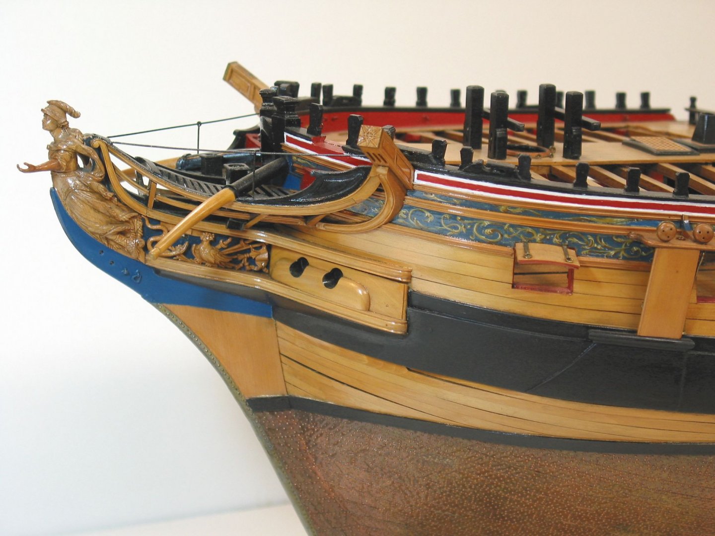
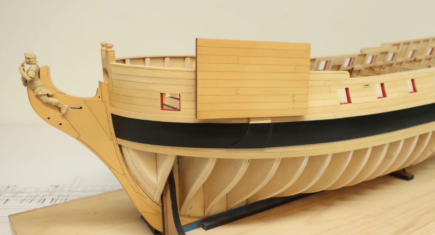
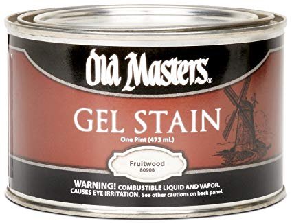
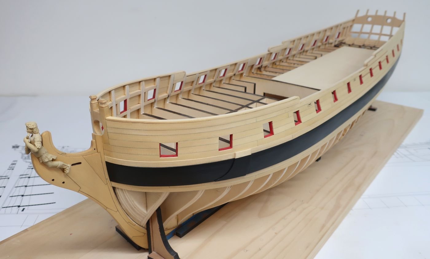
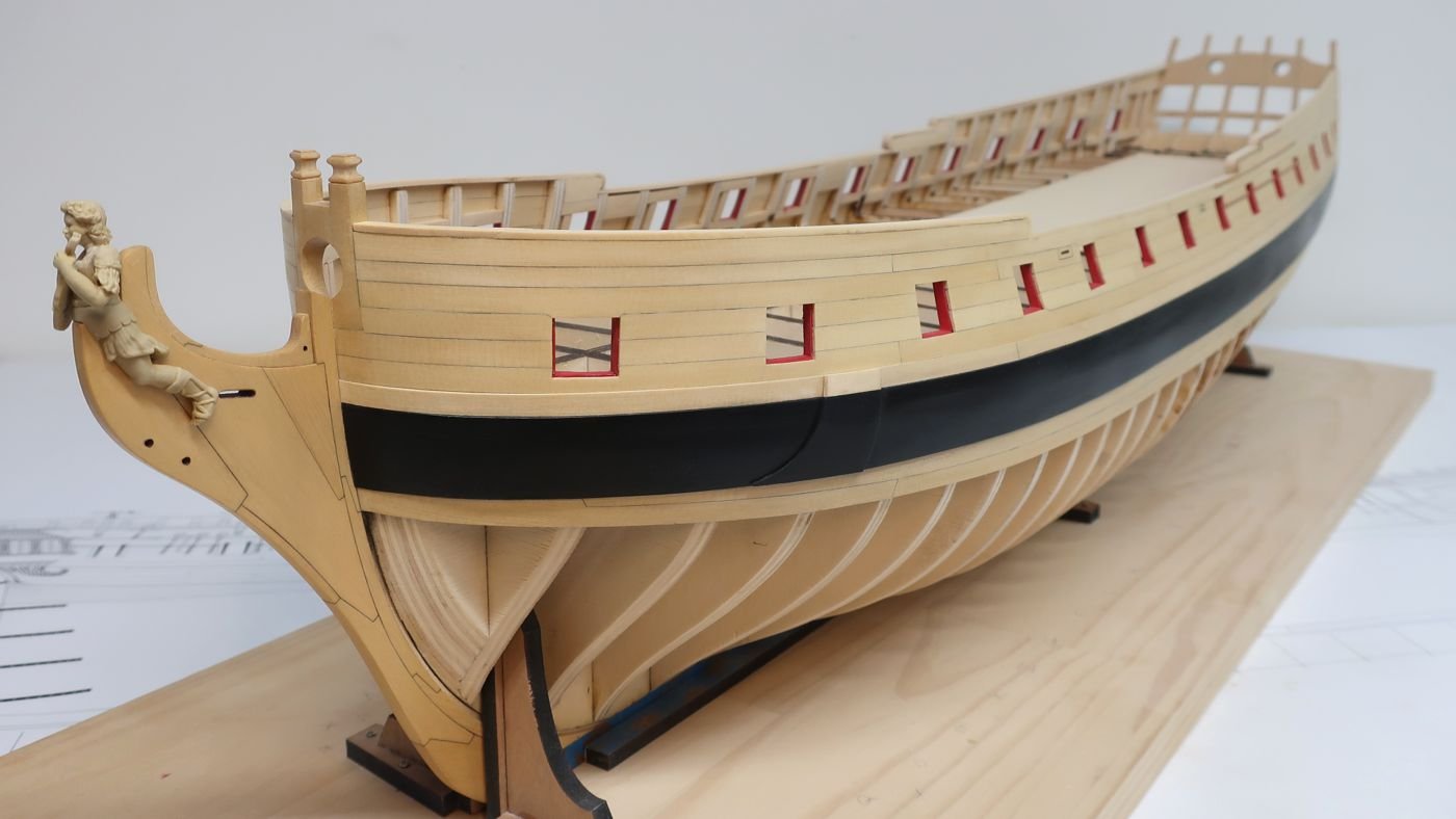
I am so thrilled with this camera....anyway, it enables me to accurately reflect the color of the yellow cedar. So now I can finally explain what is going on with my model. You may have noticed in the many images of this log that stem appears slightly different in color than the hull planking. It is a very subtle difference. This is no accident. The Yellow cedar is not the best wood for your typical stain applications. The brighter and lighter hull planking is what the Cedar looks like with just some wipe on poly. About three coats of that above the wales. I like the natural look of the cedar very much as shown on the hull planking. I think its beautiful and I could live with it just fine. But because some folks prefer a darker medium tone, I started experimenting on some scrap wood when I built my longboat. I bought probably $500 worth of various stains. I tested them vigorously. Most failed the test miserably. All "penetrating" stains.....every last one of them, failed. Just like when you stain basswood, it was dark and blotchy and just awful. I tried 4 brands. DO NOT USE A PENETRATING STAIN ON YELLOW CEDAR!!! Then I tried about 4 brands of gel stain. I bought 3 or 4 colors to test from each brand. Once again, every last test was a dismal failure. But then I tried this one color......from one specific brand of gel stain which is non-penetrating. It is Old Masters - fruitwood gel stain. After about six tests with this particular color and only from this brand.....I tried other brands and other Old Masters colors....it was horrible. But there was something very different with this particular color. The surface of the cedar was sanded with 320 grit sandpaper. Three coats of wipe on poly was applied. This was allowed to fully dry overnight and its very important that you give it a day. That will look like the untreated planking above the wales....very beautiful. But then with a soft lint free cloth, apply some fruitwood gel stain. The longer you let it sit on the wood the darker it will get. I wiped it off and buffed it clean after only about 1 minute. It is not penetrating so you will be able to wipe it all off which tones the wood just a bit to your liking. I do about a six inch area and wipe it off. Then do the adjacent area. The two areas blend together well without worrying that the overlap will be darker. I let this dry overnight....and applied another coat of wipe on poly. The result is a slightly darker wood that actually resembles boxwood a lot closer. I like the color a lot. Not Costello boxwood but it looks like the real English stuff. The color of many contemporary models. It evens out the color and looks great. So yes, if you dont like the really light....more yellow color of Cedar, You can change it to look like the swatch/mock-up in the photos. My stem was also treated like this and its why it appears different than the color of the planking. I have also sanded it and reapplied on the stem many times and it came out very even and you cant see where I did that touch up. But remember.....I tested so many brands and colors. This is literally the only one that worked with really really good results. I also simulated some treenails on that mock-up. So once I get the planking all completed and add the treenails, I will coat the external planking to match the stem. All things considered, I think this was a very successful although expensive experiment. I wanted to save you guys that time and money. Also save you the chance of ruining your model. So make a mock-up and test with this Brand and color of gel stain and decide for yourself. Compare with the contemporary model of Minerva in the Rogers collection below.
- 1,784 replies
-
- 21
-
-
- winchelsea
- Syren Ship Model Company
- (and 1 more)
-
I was going to do that but after a few days I realized my phone's camera just wasnt good enough. So I splurged on a new Cannon. I am very happy so far with it. Chuck
- 1,784 replies
-
- 1
-
-
- winchelsea
- Syren Ship Model Company
- (and 1 more)
-
Just trying out my new camera guys. Really crisp photos now I just have to get the color and settings correct.

- 1,784 replies
-
- 19
-
-
- winchelsea
- Syren Ship Model Company
- (and 1 more)
-
Nicely done......great looking puzzle. Do you have a link to that one. I would love to build that puzzle. Where did you get it? Chuck
-
I actually chisel out the big stuff. Less mess. Easier to breath. Then I sand with 120 grit to clean it up. Chuck
- 1,784 replies
-
- 1
-
-
- winchelsea
- Syren Ship Model Company
- (and 1 more)
-
HMS Winchelsea (1764) 32 gun frigate GROUP PROJECT INFO
Chuck replied to Chuck's topic in Group Projects on Model Ship World
You got that right....If this looks familiar to you guys building the model shipways Confederacy kit.....my design, it should. This is the Chinese pirated version by Snail, a banned company from China. If it isnt nailed down they will rip it off. They have no morals at all. Snail is one of the worst companies out their with the owner blatantly stealing. This is the guy who ripped off the Triton plans as well. So he will certainly be prowling to get his hands on the plans for Winnie. These guys are members of other forums who promote Chinese pirated kits. So even if you have friends over there, I know many of you are dual members of these sites. Please do not share the Winnie plans with any members of those other sites. Build it for yourself only....and if your friends are interested, have them sign up here to join the group. Dont share them. The owner of Snail has made this comment about it and where they got the plans on a Chinese website....not to hijack this thread. But its nuts. I give it six months before the Winnie shows up in China. So please do not share or post these drawings....stick to the scroll saw. Here is what he said pasted right from the Chinese forum..."Thank you for your continued care and attention watching our kit developments. This time, we want to produce a 1:64 appearance (non-full rib) federal sailing ship. This legendary kit is developed according to foreign drawings by a master kit designer in America. We reproduce it for you" Compare with my design below.....yet some sites and forums believe it isnt a copy and this is OK......so please do NOT distribute these plans at all. If the Winnie plans get out and I see this happen, then yes it will probably be the last project I develop.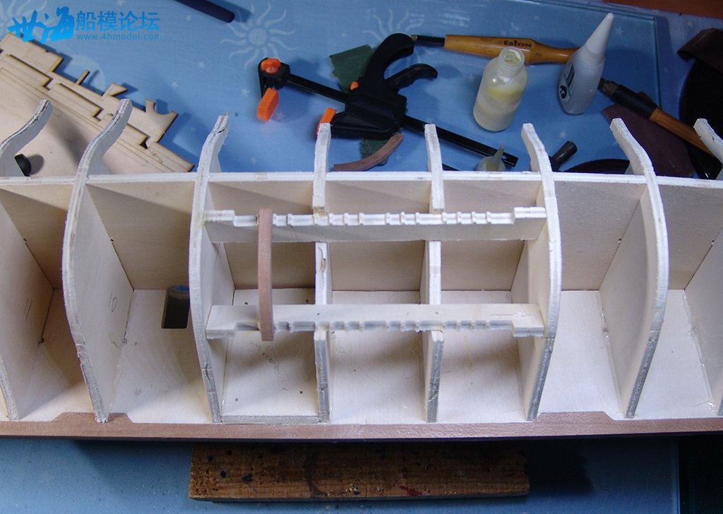
-
That looks great Ryland. Its so great to see you up and around. Patti and I have been thinking about you and we were quite worried. Time to slow down and get more shop time in. Hope to see you guys real soon. Chuck
- 263 replies
-
- 3
-
-
- Medway Longboat
- Syren Ship Model Company
- (and 1 more)
-
She is looking really good. Great progress.
-
Awesome...time to start putting that stem together.
-
HMS Winchelsea (1764) 32 gun frigate GROUP PROJECT INFO
Chuck replied to Chuck's topic in Group Projects on Model Ship World
No sorry I cant supply those. -
Nope but that shouldnt stop you from getting that stem put together and sanded with the proper bevel. Maybe another week or so.