Chuck
-
Posts
9,695 -
Joined
-
Last visited
Content Type
Profiles
Forums
Gallery
Events
Everything posted by Chuck
-
 That would be easy enough to add in the kit.....what I can do is finish off three top strakes and take some photos, then add the garboard and take more. It can be an option for folks. They can also just add the garboard and two strakes along the sheer like the one conteporary model. This way, everyone can choose which they prefer. Chuck
- 269 replies
-
- 13
-

-
- Queen Anne Barge
- Syren Ship Model Company
- (and 1 more)
-
Thanks Yes I have been doing my own laser cutting for about 1 1/2 years now. I couldnt possibly make the parts in the amounts needed without having my own laser cutter. Its a fun machine to have in the shop. Chuck
- 269 replies
-
- 5
-
-
- Queen Anne Barge
- Syren Ship Model Company
- (and 1 more)
-
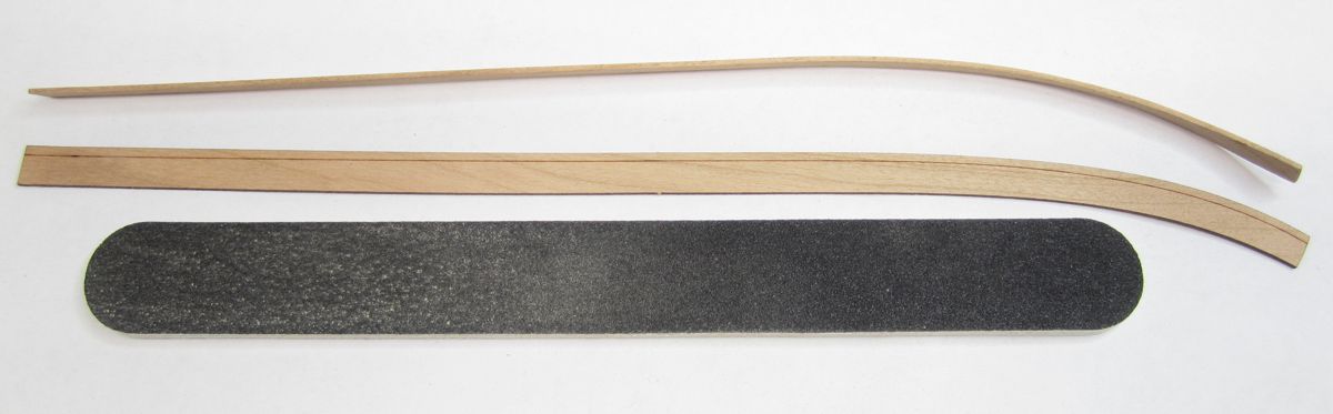
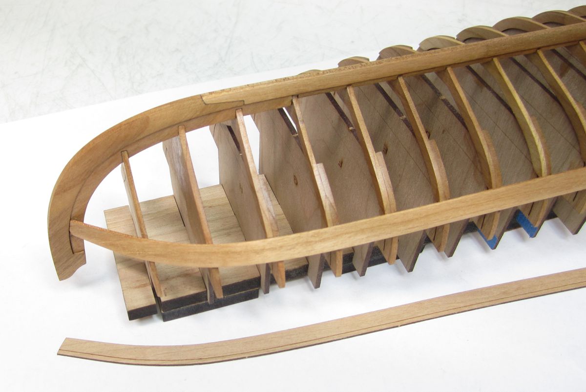
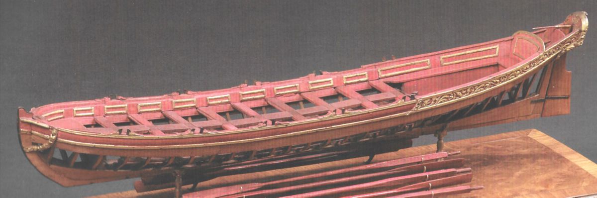
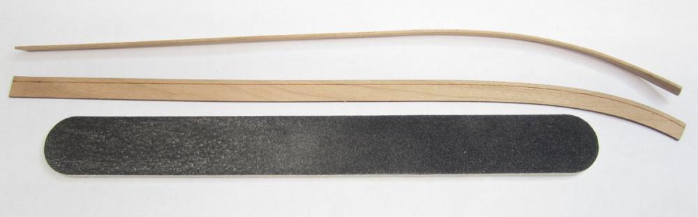
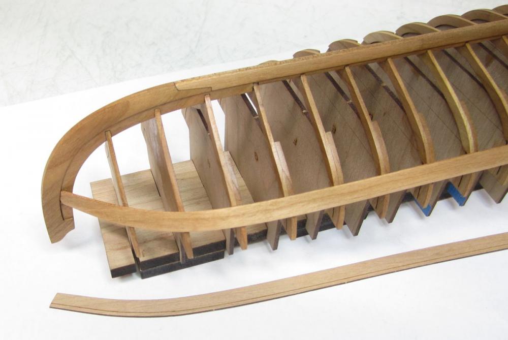
Just a quick update on the Queen Anne Style Barge. Note that the planking on a Barge of this period was less than 1" thick. That is very thin stuff. I am using 1/32" Cherry to laser cut the planking. Its actually thicker than it should be at this scale but a very nice thickness to work with. After making many blocks today, I decided to try and fit my first plank on the model. The planks will be pre-spiled. In addition, a laser etched reference line will be on the clinker strakes. There are only three strakes on the barge like the contemporary models I showed. Only the bottom two planks are lapstrake or clinker. This will be a great introduction to this type of planking. You will bevel the strake from the reference line to the edge in preparation for the plank above it(or as the model is upside down, below it). It will be beveled ahead of time after you gently remove the laser char from its edges. Then you bend the plank just a bit as shown. Using an emery board works great for this. It fits really good and no forcing is needed to put it in position. Just a little glue on each frame....working two or three at a time from the bow towards the stern. The forward end of the strake is beveled to sit nicely against the stem and rabbet. I will put the sister plank on the other side and then the two aft sections of this same strake. That will really make the model solid and safe. So I want to get this done ASAP. The last two strakes will follow shortly after. Also examine this image of a similar barge. The reason why I chose cherry was also for its color. The contemporary model below is basically the same color and I am very pleased with the cherry so far. The barge below also has only two strakes from the sheer. I will be going with three so you can tell its clinker planked. But I wont be adding the garboard. There were many different variations on contemporary examples. I will be going with three strakes like this barge below. Chuck

- 269 replies
-
- 17
-
-
- Queen Anne Barge
- Syren Ship Model Company
- (and 1 more)
-
I actually switched the fixture over to LED bulbs. The bulb isnt glass. It is plastic and these bulbs are so much brighter. So it worked out in the end. And the hop was due for a good cleaning anyway. So no harm done other than the loss of a day. Yes there were some choice words going through my head the entire time I was cleaning up all of those tiny shards. Chuck
- 1,051 replies
-
- 10
-
-
- cheerful
- Syren Ship Model Company
- (and 1 more)
-
Spent the afternoon fixin her all up! Its as good as new. Now to move forward tomorrow with actual new progress. Chuck
- 1,051 replies
-
- 11
-
-
- cheerful
- Syren Ship Model Company
- (and 1 more)
-
Funny Story....... A very large black wasp flew into my shop today. Seeing as I am such a genius I started swatting the wasp with a dish towel. Not being very precise with my weapon of choice, I struck the overhead fluorescent light with two.... four foot long bulbs in it. Both bulbs proceeded to fall in slow motion. The Cheerful model was directly below them. You know how the rest of the story goes. The bulbs smashed into literally billions of tiny shards of glass. A direct hit. Cheerful did take some considerable battle damage. But nothing I cant fix in a day or two. I am very happy to also report, that the same blow that inflicted damage to my model actually did send that wasp to an early, untimely and hopefully quite unpleasant end. I have ninja-like skills with a dish towel. Chuck
- 1,051 replies
-
- 22
-
-
- cheerful
- Syren Ship Model Company
- (and 1 more)
-
Greg.....One more thing. That is a very good point about working with Tite-Bond or Yellow glue. Its something I do instinctively without any thought. I too, keep a cup of water around at all times with a disposable brush. I use it to clear any of the glue that squeezes out between the joints before it dries. Its little things like that I always forget to include in the manual.....rest assured I will add that to the first installment right away. Its the only way I can keep my joinery clean and crisp. Thanks for the reminder.
- 269 replies
-
- 11
-
-
- Queen Anne Barge
- Syren Ship Model Company
- (and 1 more)
-
Thanks Greg. It depends. It depends if its a slotted joint or just two pieces butt against each other. If one piece is being inserted into a notch or a slot then it doesnt really matter much and the laser char wont interfere with the joint much. But when there is no such interlocking mechanism then yes, I do like to clear away the laser char. There is one other exception....when the piece that needs to be cleared of laser char is too fragile or its fit was made precise while designing it. Then I dont risk it. Maybe a cursory pass with some fine sandpaper. But its shape and fragility must be taken under consideration.
- 269 replies
-
- 6
-
-
- Queen Anne Barge
- Syren Ship Model Company
- (and 1 more)
-
Cutter Cheerful by iosto - 1/4" scale
Chuck replied to iosto's topic in - Build logs for subjects built 1801 - 1850
That looks great!!! Well Done -
Because much is being discussed about how kits and other projects are produced, I thought I would continue to share bits about my philosophy as I develop these two new kits. As I mentioned in one of those other topics, It is an absolute must to have a good set of plans and a good set of instructions. Not everyone is at the same level of skill. What might be second nature for some is not so clear to others. There are so many details and build sequences that Cad Drawings and pans can NOT convey effectively on their own. I am not talking about writing a book....nothing like a 300 page thing that so many desire....for heaven's sake....buy a book on the subject in addition to the kit. Instead, just enough to guide folks along but obviously more than the usual kit instructions we have all grown to hate so much. As the first installment gets off the ground for this kit, I write the instructions for it. Then I pass them along to the individual building the prototype with me. If this person has a hard time following what I have written and cant build the model, then I failed. But luckily I get tons of feedback from the prototype builder telling me what he would need or what he didnt understand. Or If I should make wording changes or add additional pictures or drawings to make it clearer. It is priceless to have this feedback....I think its a huge disservice to just produce the project and release it without this feedback. It doesnt cost anything because the folks I use are my dear friends and they actually get to build a model for free. They probably would have bought it afterwards anyway...so why not be the first and build it alongside me. Not only do they tell me if the pieces dont fit properly....but the feedback on the instructions and plans will ultimately help all of the people building it too. Here is a look at the level of detail I am talking about....I cant write a book...because you would have to pay me the price of an actual book. I cant write 50 pages on the history of Barges....these are just instructions, but very thorough instructions none-the-less. Hopefully anyway!!! PDF below...unedited and before getting any feedback. They will certainly change before the project is released. Shallop one.pdf
- 269 replies
-
- 17
-
-
- Queen Anne Barge
- Syren Ship Model Company
- (and 1 more)
-
Thanks I wont be changing the scale because too much is involved. But I will be making some in boxwood or pear as a custom order. Having said that, these will be much more $ of course. I will figure out the costs when the project is completed.
- 269 replies
-
- 5
-
-
- Queen Anne Barge
- Syren Ship Model Company
- (and 1 more)
-
I have no timeline. I dont like to rush my projects as you guys probably noticed. So whenever it gets done it gets done. I wish I could give you a better answer but its just the way I work. I am a very slow builder and designer. No installments will be released this time until after the entire model is completed. It shouldnt take long!!! LOL Famous last words right?
- 269 replies
-
- 10
-
-
- Queen Anne Barge
- Syren Ship Model Company
- (and 1 more)
-
Yes...no worries. There will be plenty of extras as most of you know I try to include for parts like this. In addition, after I complete my own carvings, I will cast them and offer a complete resin package as an aftermarket kit option. This is for the folks who wouldnt want to even try it...BUT I WOULD STRONGLY ENCOURAGE EVERYONE TO AT LEAST TRY IT. You might just surprise yourself.
- 269 replies
-
- 6
-
-
- Queen Anne Barge
- Syren Ship Model Company
- (and 1 more)
-
Yes....but not as easy as just clicking a button. Which most would assume. After resizing the templates in the drafting software (the easy part)....the laser settings will then have to be adjusted to reflect the proper speed and power settings for the smaller thickness in wood. Depending on the parts, they also may need some tweaking to adjust for the larger kerf size in relation to the smaller part size (ie the carved decorations). Plus the five or six more elaborate carvings are being done as resin castings. I cant expect folks to scratch carve those so masters will need to be made for those. So there are plenty of hours of work needed to do it correctly for the best results. But once its done the first time, its done and all parts can easily be run as quickly as the 1/2" scale versions. But its still weeks of work. After all that there are other considerations. This design concept works well for 1/2" scale. BUT Lets consider that the frames are 1/16" thick at this scale. Reducing them to 1/4" scale means using 1/32" thick stock. Or at a minimum, going with 3/64" for strength. I think using 1/32" thick frames for this design construction method would not work as the frames would be much to fragile. So once you start altering those thicknesses...it means more alterations for the parts templates and it just snowballs from there. To simply reduce everything by 50% without thinking it through would be a disaster. I know some other folks think its easily done and have talked about it in other threads. In my opinion its not as simple and a bit fantasy actually. Depending on the subject of course. Decisions would need to be made that may reduce its historical accuracy for MFG purposes or depending on the scale, a entirely different construction concept might be a better way to go. Lots to consider. I hate to be the fantasy killer to all those folks discussing the possibilities of kit production in that other topic. But its a little naive in my opinion. For most subjects anyway.
- 269 replies
-
- 13
-
-
- Queen Anne Barge
- Syren Ship Model Company
- (and 1 more)
-
Nope. Just the kit. Either in installments or as one complete unit. The plans will of course be in the first installment along with the frames, keel parts and build-board. Chuck
- 269 replies
-
- 6
-
-
- Queen Anne Barge
- Syren Ship Model Company
- (and 1 more)
-
Thank you guys. Yes an intermediate builder can do this. Those are the folks this project is directed towards. As far as making the kit in parts.....I am torn. It will either be a complete kit....OR A complete kit sold in three installments. I am trying to work all that out as the prototype gets underway. I am waiting on planking material as we speak. Once it arrives it will get into high gear. Chuck
- 269 replies
-
- 7
-
-
- Queen Anne Barge
- Syren Ship Model Company
- (and 1 more)
-
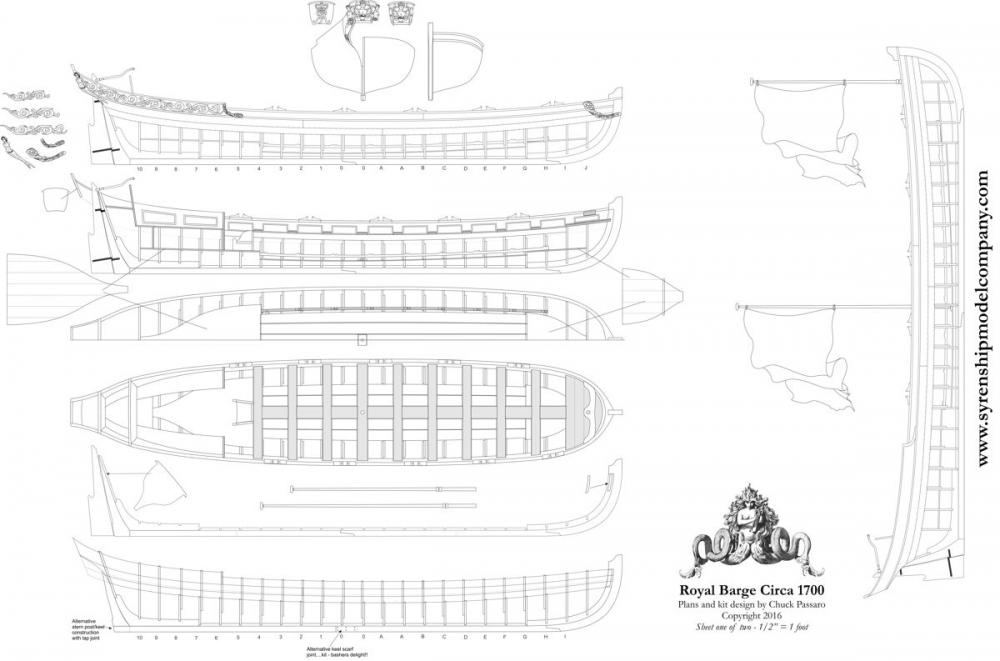
Just wanted to give all of you a more detailed look at what the new Queen Anne Style Royal Barge project will look like. You are looking at the preliminary draft for the plans. A PDF is below for a more detailed look. I am not worried about theft because there are no laser cut parts or templates shown on this sheet. I removed those. As the project and prototype gets built, more details will be added to aid the builder. Including those parts which were removed as theft prevention. This is why it is so important to have someone else build the project before its released. They will give me feedback on what additional views and parts would be helpful to include on the plan sheets. And when its completed they should be quite detailed....even though I think what is shown is probably already detailed enough for most folks. As you can see. This sheet includes many views of the model at various stages of its construction so those elements can be more easily seen. This includes a planking expansion on the bottom of the sheet. With the plans fully developed all that is left to do is build the prototypes....two of them. Make adjustments...Update and embellish the plans where needed...write the instructions.....and then start on packaging and production. This will include making all laser cut parts, cast decorations...and wood decorations. The model will be nearly 19" long and 3 1/2" wide at 1/2" scale. It will very closely resemble the contemporary model pictured. Let me know if you have any questions. Chuck queenannebargeplanmsw.pdf

- 269 replies
-
- 25
-
-
- Queen Anne Barge
- Syren Ship Model Company
- (and 1 more)
-
The sizes arent based on looks and instead based on factual data and tables....whatever you decide to go with its fine...but it will be much too large historically speaking. Again its just my opinion....but rather than just try three sizes of blocks and 4 sizes of rope for the tackles willy-nilly. It is best to refer to the historical tables and contemporary sources for rope sizes. Basically they used 6" blocks...give or take, depending on the size of the gun. And the appropriate sized rope for a 6" block which in my opinion is around 1" to maybe 1 1/4". I suppose you could maybe go as large as .018 rope for the tackles but its pushing it to the higher end of the spectrum.
- 843 replies
-
- 2
-
-
- niagara
- model shipways
- (and 2 more)
-
It looks OK but I will say that at that scale the rope you are using for the gun tackles is way, way too thick and out of scale. At this scale the blocks for the tackles would have been 6" long which translate to 3/32" blocks. The rope for the tackles would need to be .012 at the largest. Its just way too heavy. to have anything larger than that in my opinion. I would also go with .035 rope for the breech lines. But thats just my opinion for rigging those guns at 1:64 scale. Here is a photo of Cheerful guns at 1/4" scale using 1/8" blocks for the tackles and .012 rope. The breech line is .035. At 3/16" scale I wouldnt go much larger than that. Again its just an observation and my opinion. The best method to use .012 rope on the smaller blocks like 3/32" is to first stiffen the end of the rope with some white glue. Once it dries, cut the end of the rope on an angle to make it into a point like a needle. It should be stiff and sharp afterwards. It will slide through the holes in the 3/32" blocks just fine. Another alternative is to use a needle threader. No stiffening required. But I dont find that necessary as long as you can handle the small blocks in your fingers comfortably. Hope this helps. Chuck
- 843 replies
-
- 6
-
-
- niagara
- model shipways
- (and 2 more)
-
Thank You so much.....I will hopefully be back at it this weekend after I finish restocking blocks and rope. Chuck
- 1,051 replies
-
- 4
-
-
- cheerful
- Syren Ship Model Company
- (and 1 more)
-
I dont think so Antony....this is the 1700 version. That one was kind of easy to figure out. Unless I am not understanding what is wrong with the one posted. Can you elaborate? If I understand it correctly as a Yank.....before Ireland became part of the united Kingdom there were fewer bars in the flag and its the same top and bottom.
- 269 replies
-
- 9
-
-
- Queen Anne Barge
- Syren Ship Model Company
- (and 1 more)
-
Thank You...its so very confusing and contradicts other dates and standards. Maddening really. You think it would be very cut and dry what years these things were used. So many sources have different dates and different images for these. I am going with number 4.
- 269 replies
-
- 7
-
-
- Queen Anne Barge
- Syren Ship Model Company
- (and 1 more)
-
Thank you very much.....That is great information. I guess either one would work but since this will be billed as a Queen Anne Style Royal Barge I will go with that one. There will be a bust of Queen Anne on the transom. So its a perfect fit.
- 269 replies
-
- 6
-
-
- Queen Anne Barge
- Syren Ship Model Company
- (and 1 more)